

Roper 20, 30 Installation Instructions Manual
,, ,
,-.
RoPER
IMPOR’IIANT:
Installer: Leave IrWaUation Insb-uction.5 with the appliance
Homeowner Keep Installation Instiuctions for future reference.
.
’
W$ 5*tail+G &tructions for local in+ector’s uSe.,
.’
i:
) s, ‘-L-
:”
i ._ / ‘_.‘.
.,‘,&,i% ““- /;
. .’ :
.’
; I.
,.s
‘_ ( ;
.\’ :,
-”
,:
..,“.%.Z .-;
__ ,.. “,“</’ “. _
-6 ,h: F;:? A\”
~~
? . , : / <. ._c
’ -_,_ .A
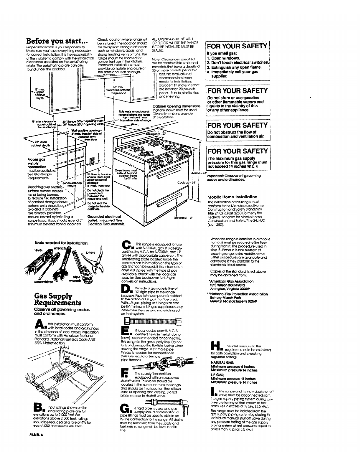
Before you start.. .
Check location where range will
ALL OPENINGS IN THE WALL
be installed The location should
OR FLOOR WHERE THE RANGE
Proper installation is your responsibility
be away from strong draft areas.
Make sure you have everyihing necessoly
such OS windows, doors. and
TE;JC;; INSTALLED MUST BE
, -,
J venrs o( ram r ne
for carrecr Insrallatlon. It IS me reSWn~lDll!N
s?rcna neonnc
ofthe installer to compl,
clearance specified on the serial/rating
nhta The rtxinlirotina elate con be,,
ranae should be located for
con7enlent us
e In the kitchen.
Recessed inst
allaticns must
Note: Clearances specified
are for combusiible walls and
Cablnef ODenIna dlmsnslons
liquids in the vicinity df this
or any other appliance.
I
w,,.a,b orcupboa,~ Mot are, shown m&t be used.
r=d - Ib - Given dlmensicns provide
lopmudta4’mh
0” clearance.
.
surfaceburners cuuse5 ‘1
risk Of being burned.
To reduce risk, Itiallation
are alreaay provraea. /
reduce hazard by lns~alling a
range hood. l-lo& should extend 5
minimum beyond front of cabinets.
Tools needed for inskliioMon.
Gas Supply
Requirements
Observe all governing codes
and ordinances.
A
This ixstallatbn must confcfm
m W’WI kc01 CC&S and ordlnonces
In the absence of lccal codes, Installatbn
must oonfwm with American Natbnal
Standard, Natbnal Fuel Gas code ANSl
2223.1 -lotest edttbn.
FOR YOUR SAFETY 1
if you smell gas:
1. Open windows.
2. Don’t touch electrical switches
3. Extinguish any open flame.
4. Immediately call your gas
supplier.
1 FOR YOUR SAFETY t
Do not store or use gasoline
or other flammable vapors and
Gfouncled electrical
outtet:
is required See
Electrical Requirements.
B
I
Input ratings shown on the
serial/rating plate are for
eleVOtim5 uo to 2.000 leet. For
elevations dbove 2.ooO feet. ratings
should be reduced at a rate of 4% lor
each KKKI feet above sea level
PANEL A
C
This range is equipped for use
n
wifh NATURAL gas. It is designcertified bv A.G.A. for NATURAL and L.f?
gases wittiappmpriaie conversion, The
serial/rating plate located under the
cti~op
has information on the type of
gas that can be used. If this information
does fd agree wifh the type of gas
available. check with the local gas
supplier. See backcover for L.P gas
conversion instructions.
D
Provide a gas supply line of
n
%” rigid pipe to the range
location. Pipe
joint
compounds resistant
to the action of L.P. gas must be used.
With L.P gas, piping or tubing size can
be K” minimum. L.P gas suppliers usually
determine the size and malerials used
on their system
E
If local codes permit. A.G.A.
I cetiifred flexible metal tubina
(new) is recommended for connecting
this
range
to the gas supply line. Do not
kink of damage the flexible tubing when
moving the range. A Y9’ male pipe
thread is needed for connection to
The supply line shall be
6dPPed with an aPDrOVed
shutoff
valve
This valve should be
loabd in the same rcom as the ronae
and
should be in a location that allows
ease of opening and closing. Do not
block access to shutoff valve.
G
If rigld
m suo~lv line. o combindon of
pipe fittings h&t be used to obtain an
in-line connection to the range. All sfralns
must be removed from the supply and
fuel lines so range will be level and in
line.
(r
lmportanl: Observe all governing
codes and ordlnanceo.
Mobile Home instaiiation
The installation of this range must
conform to the Manufactured Home
Construction and Safety Standards,
Title 24 CFR. Part 3280 (formerly the
Federal Standard for Mobile Home
Construction and Safety, Title 24. HUD
(part
280).
When this range is installed In a mcbile
home, it must be secured to the flow
during transit. The procedure used in
steo 8.Panel I3 Isonemsthcdof
se&ring range to the mobile home.
Other p&edures are avallable and
adequate If they ccnfotm to the
standards listed above,
Copies of the standard listed above
may be obtaIned from:
‘Amedcan Gas ksoclatlon
15% Wilson Boulevard
Mlngton.Vlrglnla 22209
“National Flm ProtectIon Assoclallon
Battety March Park
Qulncy, Massachusetts 02169
H
n
The inlet pressure to the
regulator should be as follows
for both operation and checking
regulator setting:
NATURAL GAS:
Mlnlmum pressure 6 Inches
Maxlmum pressure 14 Inches
1.P GAS;
Mlnlmum pressure 11 Inches
Maxlmum pressure 14 Inches
I
The range and its lndlvlduol shut-off
l
valve must be discmnected from
the gas supply piping system during any
presurre testing of that system at test
pressures in excess of k psig (3.5 kPa).
The range must be isolated from the
gas supply plp~ng system by closing 11s
indrvidual manual shut-oft valve during
any pressure testing of the gas supply
pIpIng system ai test pressures equal to
or less than % psig [3.5 kPa].
 Loading...