

Page 1

ROOTS
ROOTS
ROOTS
BLOWERS EXHAUSTERS COMPRESSORS
™™
INSTALLATION OPERATION MAINTENANCE
❏In event of trouble during installation or operation,
do not attempt repairs of ROOTS furnished
equipment. Notify ROOTS, giving all nameplate
information plus an outline of operating conditions
and a description of the trouble. Unauthorized
attempts at equipment repair may void ROOTS
warranty.
❏Units out of warranty may be repaired or adjusted
by the owner.It is recommended that such work be
limited to the operations described in this manual,
using ROOTS™parts. Good inspection and
maintenance practices should reduce the need
for repairs.
NOTE:Information in this manual is correct as of the
date of publication. ROOTS reserves the right to make
design or material changes without notice, and without
obligation to make similar changes on equipment of
prior manufacture.
For your nearest ROOTS Office, dial our Customer
Service Hot Line toll free; 1 877 363 ROOT(S) (7668)
or direct 281-966-4700.
DO THESE THINGS TO GET THE MOST FROM YOUR ROOTS
™
BLOWER
CONTENTS
INFORMATION SUMMARY . . . . . . . . . . . 1
S
AFETY PRECAUTIONS . . . . . . . . . . . . 2
O
PERATING LIMITATIONS . . . . . . . . . . . 2
I
NSTALLATION . . . . . . . . . . . . . . . . . . . 3
L
UBRICATION . . . . . . . . . . . . . . . . . . . 6
O
PERATION . . . . . . . . . . . . . . . . . . . . 7
O
PERATING CHARACTERISTICS ..............8
❏Check shipment for damage.If found, file claim
with carrier and notify ROOTS.
❏Unpack shipment carefully, and check contents
against Packing List.Notify ROOTS if a
shortage appears.
❏Store in a clean, dry location until ready for
installation. Lift by methods discussed under
INSTALLATION to avoid straining or distorting the
equipment. Keep covers on all openings. Protect
against weather and corrosion if outdoor storage
is necessary.
❏Read OPERATING LIMITATIONS and
INSTALLATION sections in this manual and plan
the complete installation.
❏Provide for adequate safeguards against accidents
to persons working on or near the equipment during
both installation and operation. See SAFETY
PRECAUTIONS .
❏Install all equipment correctly. Foundation design
must be adequate and piping carefully done.Use
recommended accessories for operating protection.
❏Make sure both driving and driven equipment is
correctly lubricated before start-up.
See LUBRICATION.
❏Read starting check points under OPERATION. Run
equipment briefly to check for installation errors and
make corrections.Follow with a trial run under
normal operating conditions.
TROUBLESHOOTING . . . . . . . . . . . . . . 9
MAINTENANCE/REPLACEMENTS
UNIVERSAL RAI
®
SERIES BLO WERS ...........10
RAM
™
SERIES BLOWERS .........................14
F
IGURES ...........................................18
TABLES .............................................22
A
SSEMBLY DRAWINGS .........................26
PARTS LIST .......................................31
US $3.00, Canada $4.50
IRB-180-102
Rev. 12/02
UNIVERSAL RAI®& RAM
™
SERIES
Page 2

ROOTS™products are sold subject
to the current General terms of
Sale, GTS-5001 and Warranty
Policy WP-5020. Copies are
available upon request.
Contact your local ROOTS Office
or ROOTS Customer Service
Hot Line 1.877.363.ROOT(S) (7668).
Page 3

2For your nearest ROOTS Office, dial our Customer Service Hot Line 1 877 363 ROOTS (7668).
SAFETY PRECAUTIONS
It is important that all personnel obser ve safety
precautions to minimize the chances of injury.
Among many considerations, the following should
be particularly noted:
• Blower casing and associated piping or accessories
may become hot enough to cause major skin burns
on contact.
• Internal and external rotating parts of the blower
and driving equipment can produce serious physical
injuries. Do not reach into any opening in the
blower while it is operating, or while subject to
accidental starting. Protect external moving parts
with adequate guards.
• Disconnect power before doing any work, and avoid
bypassing or rendering inoperative any safety or
protective devices.
• If blower is operated with piping disconnected,
place a strong coarse screen over the inlet and
avoid standing in the discharge air stream.
CAUTION: Never cover the blower inlet with
your hand or other part of body.
•Stay clear of open inlet piping (suction area) of
pressure blowers, and the open discharge blast
from vacuum blowers.
•Stay clear of the blast from pressure relief valves
and the suction area of vacuum relief valves.
• Use proper care and good procedures in handling,
lifting, installing, operating and maintaining the
equipment.
• Casing pressure must not exceed 25 PSI
(1725 mbar) gauge.Do not pressurize vented
cavities from an external source, nor restrict the
vents without first consulting ROOTS.
• Do not use air blowers on explosive or
hazardous gases.
• Other potential hazards to safety may also be
associated with operation of this equipment. All
personnel working in or passing through the area
should be trained to exercise adequate general
safety precautions.
OPERATING LIMITATIONS
A ROOTS™blower or exhauster must be operated
within certain approved limiting conditions to enable
continued satisfactory performance.Warranty is
contingent on such operation.
Maximum limits for pressure, temperature and speed
are specified in TABLE 1 for various models & sizes
of blowers & exhausters.These limits apply to all units
of normal construction, when operated under
standard atmospheric conditions. Be sure to arrange
connections or taps for thermometers and pressure
or vacuum gauges at or near the inlet and discharge
connections of the unit.These, along with a good
tachometer, will enable periodic checks of
operating conditions.
PRESSURE – The pressure rise, between inlet and
discharge, must not exceed the figure listed for the
specific unit frame size concerned. Also, in any system
where the unit inlet is at a positive pressure above
atmosphere a maximum case rating of 25 PSI gauge
(1725 mbar) should not be exceeded without first
consulting the ROOTS. Never should the maximum
allowable differential pressure be exceeded.
On vacuum service, with the discharge to atmospheric
pressure, the inlet suction or vacuum must not be
greater than values listed for the specific frame size.
TEMPERATURE – Blower & exhauster frame sizes are
approved only for installations where the following
temperature limitations can be maintained in service:
•Measured temperature rise must not exceed listed
values when the inlet is at ambient temperature.
Ambient is considered as the general temperature
of the space around the unit.This is not outdoor
temperature unless the unit is installed outdoors.
• If inlet temperature is higher than ambient, the
listed allowable temperature rise values must be
reduced by 2/3 of the difference between the
actual measured inlet temperature and the
ambient temperature.
• The average of the inlet and discharge temperature
must not exceed 250°F.(121°C).
SPEED – These blowers & exhausters may
be operated at speeds up to the maximum listed for
the various frame sizes.They may be direct coupled
to suitable constant speed drivers if pressure/temperature conditions are also within limits. At low speeds,
excessive temperature rise may be a limiting factor.
Special Note: The listed maximum allowable temperature rise for any particular blower & exhauster may
occur well before its maximum pressure or vacuum
rating is reached.This may occur at high altitude, low
vacuum or at very low speed.The units’ operating limit
is always determined by the maximum rating reached
first. It can be any one of the three: Pressure,
Temperature or Speed.
Page 4

3
©2002 Dresser, Inc.all rights reser ved.
ROOTS, RAM, URAI and WHISPAIR are trademarks of Dresser, Inc.
Dresser Design and Universal RAI are registered trademarks of Dresser, Inc.
ROOTS™blowers & exhausters are treated after factory
assembly to protect against normal atmospheric
corrosion.The maximum period of internal protection
is considered to be one year under average conditions,
if shipping plugs & seals are not removed.Protection
against chemical or salt water atmosphere is not
provided. Avoid opening the unit until ready to start
installation, as corrosion protection will be quickly lost
due to evaporation.
If there is to be an extended period between installation and start up, the following steps should be taken
to ensure corrosion protection.
❏ Coat internals of cylinder, gearbox and drive end
bearing reservoir with Nox-Rust VCI-10 or
equivalent.Repeat once a year or as conditions
may require.Nox-Rust VCI-10 is petroleum
soluble and does not have to be removed before
lubricating. It may be obtained from Daubert
Chemical Co., 2000 Spring Rd., Oak Brook, Ill.
60521.
❏Paint shaft extension, inlet and discharge flanges,
and all other exposed surfaces with Nox-Rust
X-110 or equivalent.
❏Seal inlet, discharge, and vent openings.It is not
recommended that the unit be set in place, piped
to the system, and allowed to remain idle for
extended periods.If any par t is left open to the
atmosphere, the Nox-Rust VCI-10 vapor will
escape and lose its effectiveness.
❏Protect units from excessive vibration
during storage.
❏Rotate shaft three or four revolutions every
two weeks.
❏Prior to start up, remove flange covers on both
inlet and discharge and inspect internals to insure
absence of rust. Check all internal clearances.
Also, at this time, remove gearbox and drive end
bearing cover and inspect gear teeth and bearings
for rust.
Because of the completely enclosed unit design,
location of the installation is generally not a critical
matter.A clean, dry and protected indoor location is
preferred.However, an outdoor location will normally
give satisfactory service. Important requirements are
that the correct grade of lubricating oil be provided for
expected operating temperatures, and that the unit be
located so that routine checking and servicing can be
performed conveniently. Proper care in locating driver
and accessory equipment must also be considered.
INSTALLATION
Supervision of the installation by a ROOTS Service
Engineer is not usually required for these units.
Workmen with experience in installing light to
medium weight machinery should be able to produce
satisfactory results. Handling of the equipment needs
to be accomplished with care, and in compliance with
safe practices.Unit mounting must be solid, without
strain or twist, and air piping must be clean, accurately
aligned and properly connected.
Bare-shaft Units: Two methods are used to handle
a unit without base. One is to use lifting lugs bolted
into the top of the unit headplates.Test them first for
tightness and fractures by tapping with a hammer.
In lifting, keep the direction of cable pull on these
bolts as nearly vertical as possible. If lifting lugs are
not available, lifting slings may be passed under the
cylinder adjacent to the headplates. Either method
prevents strain on the extended drive shaft.
Packaged Units: When the unit is furnished mounted
on a baseplate, with or without a driver, use of lifting
slings passing under the base flanges is required.
Arrange these slings so that no strains are placed on
the unit casing or mounting feet, or on any mounted
accessory equipment. DO NOT use the lifting lugs in
the top of the unit headplates.
Before starting the installation, remove plugs, covers
or seals from unit inlet and discharge connections
and inspect the interior completely for foreign material.
If cleaning is required, finish by washing the cylinder,
headplates and impeller thoroughly with a petroleum
solvent.Turn the drive shaft by hand to make sure
that the impellers turn freely at all points. Anti-rust
compound on the connection flanges and drive
shaft extension may also be removed at this time
with the same solvent.Cover the flanges until ready
to connect piping.
Mounting
Care will pay dividends when arranging the unit
mounting.This is especially true when the unit is
a “bare-shaft” unit furnished without a baseplate.
The convenient procedure may be to mount such a
unit directly on a floor or small concrete pad, but
this generally produces the least satisfactory results.
It definitely causes the most problems in leveling and
alignment and may result in a “Soft Foot” condition.
Correct soft foot before operation to avoid unnecessary
loading on the casing and bearings. Direct use of building
structural framing members is not recommended.
For blowers without a base, it is recommended that a
well anchored and carefully leveled steel or cast iron
mounting plate be provided.The plate should be at
Page 5

4For your nearest Roots Office, dial our Customer Service Hot Line 1 877 363 ROOTS (7668).
least 1 inch (25 mm) thick, with its top surface
machined flat, and large enough to provide leveling
areas at one side and one end after the unit is mounted. It should have properly sized studs or tapped holes
located to match the unit foot drilling. Proper use of a
high quality machinist’s level is necessary for adequate
installation.
With the mounting plate in place and leveled, set the
unit on it without bolting and check for rocking. If it is
not solid, determine the total thickness of shims
required under one foot to stop rocking.Place half of
this under each of the diagonally-opposite short feet,
and tighten the mounting studs or screws.Rotate the
drive shaft to make sure the impellers turn freely. If the
unit is to be direct coupled to a driving motor, consider
the height of the motor shaft and the necessity for it to
be aligned very accurately with the unit shaft. Best unit
arrangement is directly bolted to the mounting plate
while the driver is on shims of at least 1/8 inch (3mm)
thickness.This allows adjustment of motor position in
final shaft alignment by varying the shim thickness.
Aligning
When unit and driver are factory mounted on a
common baseplate, the assembly will have been
properly aligned and is to be treated as a unit for
leveling purposes.Satisfactory installation can be
obtained by setting the baseplate on a concrete slab
that is rigid and free of vibration, and leveling the top
of the base carefully in two directions so that it is free
of twist.The slab must be provided with suitable anchor
bolts.The use of grouting under and partly inside the
leveled and shimmed base is recommended.
It is possible for a base-mounted assembly to become
twisted during shipment, thus disturbing the original
alignment. For this reason, make the following checks
after the base has been leveled and bolted down.
Disconnect the drive and rotate the unit shaft by hand.
It should turn freely at all points. Loosen the unit foot
hold-down screws and determine whether all feet are
evenly in contact with the base. If not, insert shims as
required and again check for free impeller rotation.
Finally, if unit is direct coupled to the driver, check
shaft and coupling alignment carefully and make any
necessary corrections.
In planning the installation, and before setting the unit,
consider how piping arrangements are dictated by the
unit design and assembly. Dr ive shaft rotation must be
established accordingly and is indicated by an arrow
near the shaft.
Typical arrangement on vertical units has the drive
shaft at the top with counterclockwise rotation and
discharge to the left. Horizontal units are typically
arranged with the drive shaft at the left with counterclockwise rotation and discharge down.See Figure 3
and 4 for other various unit arrangements and
possible conversions.
When a unit is DIRECT COUPLED to its driver, the
driver RPM must be selected or governed so as not to
exceed the maximum speed rating of the unit.Refer to
Table 1 for allowable speeds of various unit sizes.
A flexible type coupling should always be used to
connect the driver and unit shafts.
Coupling halves must be accurately aligned, and a
sufficient gap between shaft ends provided so that side
strains and end thrust on either shaft are avoided or
minimized.This will require considerable care in the
mounting of the driver.The two shafts must be in as
near perfect alignment in all directions as possible, and
the gap must be established with the motor armature
on its electrical center if end-play exists.
The following requirements of a good installation are
recommended. Coupling halves must be fitted to the
two shafts with a line to line thru .001” interference fit.
Coupling halves must be warmed up, so that only light
tapping is required to install them. Maximum deviation
in offset alignment of the shafts should not exceed
.005” (.13 mm) total indicator reading, taken
on the two coupling hubs.Maximum deviation from
parallel of the inside coupling faces should not exceed
.001” (.03 mm) when checked at six points around
the coupling.
When a unit is BELT DRIVEN, the proper selection of
sheave diameters will result in the required unit speed.
This flexibility can lead to operating temperature problems caused by unit speed being too low. Make sure
the drive speed selected is within the allowable range
for the specific unit size, as specified under Table 1.
Belt drive arrangements usually employ two or more
V-belts running in grooved sheaves. Installation of the
driver is less critical than for direct coupling, but its
shaft must be level and parallel with the unit shaft.
The driver should be mounted on the inlet side of
a vertical unit (horizontal piping) and on the side
nearest to the shaft on a horizontal unit. The driver
must also be mounted on an adjustable base to permit
installing, adjusting and removing the V-belts.To
position the driver correctly, both sheaves need to be
mounted on their shafts and the nominal shaft center
distance known for the belt lengths to be used.
Install the unit sheave so that its inner hub face is not
more than 1/8 inch (3mm) from the drive end cover.
See page 18 for minimum sheave diameter and
maximum sheave width.The shaft fit should be such
that the sheave can be worked into place by hand or
by very light tapping. A tight or driving fit can damage
a bearing, and may cause internal unit damage by
forcing the impeller out of its normal operating position.
A loose fit or wobbly sheave will cause vibration, and
may result in shaft breakage.
CAUTION: Couplings as well as sheave bushings
must have a slight slide fit with the unit shaft such
that they can be installed in place by hand.Any force
used to install them could change unit end clearance
resulting in unit damage. If interference fit is desired for
the coupling, the coupling hub should be heated and
shrunk on the shaft. For engine drives, use “locktite”
between the coupling hubs and the shafts and on the
threads of the coupling set screws.
Page 6

5
©2002 Dresser, Inc.all rights reser ved.
ROOTS, RAM, URAI and WHISPAIR are trademarks of Dresser, Inc.
Dresser Design and Universal RAI are registered trademarks of Dresser, Inc.
The driver sheave should also be mounted as close to
its bearing as possible, and again should fit the shaft
correctly. Position the driver on its adjustable base so
that 2/3 of the total movement is available in the
direction away from the unit, and mount the assembly
so that the face of the sheave is accurately in line with
the unit sheave.This position minimizes belt wear, and
allows sufficient adjustment for both installing and
tightening the belts. After belts are installed, adjust
their tension in accordance with the manufacturer’s
instructions. However, only enough tension should be
applied to prevent slippage when the unit is operating
under load. Excessive tightening can lead to early
bearing failures or shaft breakage.
Before operating the drive under power to check initial
belt tension, first remove covers from the unit
connections. Make sure the interior is still clean, then
rotate the shaft by hand. Place a coarse screen over
the inlet connection to prevent anything being drawn
into the unit while it is operating, and avoid standing
in line with the discharge opening. Put oil in the sumps
per instructions under LUBRICATION.
Piping
Before connecting piping, remove any remaining
anti-rust compound from Unit connections. Clean pipe
should be no smaller than unit connections. In addition,
make sure it is free of scale, cuttings, weld beads, or
foreign material of any kind.To further guard against
damage to the unit, especially when an inlet filter is not
used, install a substantial screen of 16 mesh backed
with hardware cloth at or near the inlet connections.
Make provisions to clean this screen of collected
debris after a few hours of operation.It should be
removed when its usefulness has ended, as the wire
will eventually deteriorate and small pieces going into
the unit may cause serious damage.
Pipe flanges or male threads must meet the unit
connections accurately and squarely. DO NOT attempt
to correct misalignment by springing or cramping the
pipe. In most cases this will distort the unit casing and
cause impeller rubbing. In severe cases it can prevent
operation or result in a broken drive shaft.For similar
reasons, piping should be supported near the unit to
eliminate dead weight strains.Also, if pipe expansion is
likely to occur from temperature change, installation of
flexible connectors or expansion joints is advisable.
Figure 2 represents an installation with all accessory
items that might be required under various operating
conditions. Inlet piping should be completely free of
valves or other restrictions.When a shut-off valve can
not be avoided, make sure a full size vacuum relief is
installed nearest the unit inlet.This will protect against
unit overload caused by accidental closing of the
shut-off valve.
Need for an inlet silencer will depend on unit speed and
pressure, as well as sound-level requirements in the
general surroundings.An inlet filter is recommended,
especially in dusty or sandy locations. A discharge
silencer is also normally suggested, even though
Whispair units operate at generally lower noise levels
than conventional rotary blowers. Specific recommendations on silencing can be obtained from ROOTS.
Discharge piping requires a pressure relief valve, and
should include a manual unloading valve to permit
starting the unit under no-load conditions. Reliable
pressure/vacuum gauges and good thermometers at
both inlet and discharge are recommended to allow
making the important checks on unit operating conditions.The back-pressure regulator shown in Figure 2
is useful mainly when volume demands vary while the
unit operates at constant output. If demand is constant,
but somewhat lower than the unit output, excess may
be blown off through the manual unloading valve.
In multiple unit installations where two or more units
operate with a common header, use of check valves
is mandatory.These should be of a direct acting or free
swinging type, with one valve located in each line
between the unit and header.Properly installed, they
will protect against damage from reverse rotation
caused by air and material back-flow through an
idle unit.
After piping is completed, and before applying power,
rotate the drive shaft by hand again.If it does not move
with uniform freedom, look for uneven mounting, piping
strain, excessive belt tension or coupling misalignment.
DO NOT operate the unit at this time unless it has
been lubricated per instructions.
Page 7

6For your nearest ROOTS Office, dial our Customer Service Hot Line 1 877 363 ROOTS (7668).
LUBRICATION: For Units with a Grease Lubricated
Drive End
A simple but very effective lubrication system is
employed on the drive shaft end bearings.Hydraulic
pressure relief fittings are provided to vent any excess
grease, preventing pressure build-up on the seals.
A restriction plug and metering orifice prevent loss of
lubricant from initial surges in lubricant pressure but
permit venting excess lubricant under steadily rising
pressures.
When servicing drive end bearings, use a NLGI #2
premium grade grease with 300°F (149°C) service
temperature and moisture resistance and good
mechanical stability. Using a pressure gun, slowly
force new lubricant into each drive end bearing
housing until traces of clean grease comes out of
the relief fitting.
After a long shutdown, it is recommended that the
grease fittings be removed, the old grease flushed out
with kerosene or #10 lubricating oil, drained thoroughly,
and bearings refilled with new grease.Be sure grease
relief fittings are reinstalled. Grease should be added
using a hand operated grease gun to the drive end
bearings at varying time intervals depending on duty
cycle and RPM.Table 4 has been prepared as a
general greasing schedule guide based on average
operating conditions.More frequent intervals may be
necessary depending on the grease operating
temperature and unusual circumstances.ROOTS
™
synthetic grease (ROOTS P/N T20019-) is highly
recommended.
LUBRICATION: For Units with Splash Lubrication
on Both Ends
Bearings and oil seals are lubricated by the action of
the timing gears or oil slingers which dip into the main
oil sumps causing oil to splash directly on gears and
into bearings and seals. A drain port is provided below
each bearing to prevent an excessive amount of oil in
the bearings. Seals located inboard of the bearings in
each headplate effectively retain oil within the sumps.
Any small leakage that may occur should the seals
wear passes into a cavity in each vented headplate
and is drained downward.
LUBRICATION
Oil sumps on each end of the blower are filled by
removing top vent plugs, Item (21), and filling until oil
reaches the middle of the oil level sight gauge, Item
(37), or the overflow plug.
Initial filling of the sumps should be accomplished with
the blower not operating, in order to obtain the correct
oil level.Approximate oil quantities required for blowers
of the various models and configurations are listed in
Table 3. Use a good grade of industrial type non-detergent, rust inhibiting, anti-foaming oil and of correct
viscosity per Table 2. ROOTS™synthetic oil (ROOTS
P/N 813-106-) is highly recommended.
The oil level should not fall below the middle of the
site gauge when the blower is idle.It may rise
on the gauge during operation, to an extent depending
somewhat on oil temperature and blower speed.
Proper lubrication is usually the most important single
consideration in obtaining maximum service life and
satisfactory operation from the unit. Unless operating
conditions are quite severe, a weekly check of oil level
and necessary addition of lubricant should be sufficient. During the first week of operation, check the oil
levels in the oil sumps about once a day, and watch
for leaks.Replenish as necessary.Thereafter, an
occasional check should be sufficient.It is recommended
that the oil be changed after initial 100 hours of operation. Frequent oil changing is not necessary unless theblower is operated in a very dusty location. Normal life
expectancy of petroleum based oils is about 2000
hours with an oil temperature of about 200°F (93°C).
As the oil temperature increases by increments of
15-18°F (8°C - 10°C), the life is reduced by half.
Example: Oil temperatures of 230-236°F (110°C 113°C) will produce life expectancy of 1/4 or 500 hours.
Therefore, it is considered normal to have oil change
periods of 500 hours with petroleum based oils.
Page 8

7
©2002 Dresser, Inc.all rights reser ved.
ROOTS, RAM, URAI and WHISPAIR are trademarks of Dresser, Inc.
Dresser Design and Universal RAI are registered trademarks of Dresser, Inc.
Before operating a blower under power for the first
time, recheck the unit and the installation thoroughly
to reduce the likelihood of avoidable troubles.Use the
following procedure check list as a guide, but consider
any other special conditions in the installation.
❏Be certain that no bolts, tools, rags, or debris have
been left in the blower air chamber or piping.
❏If an outdoor intake without filter is used, be sure
the opening is located so it cannot pick up dirt and
is protected by a strong screen or grille.Use of the
temporary protective screen as described under
INSTALLATION is strongly recommended.
❏Recheck blower leveling, drive alignment and
tightness of all mounting bolts if installation is not
recent. If belt drive is used, adjust belt tension
correctly.
❏Turn drive shaft by hand to make sure impellers
still rotate without bumping or rubbing at any point.
❏Make sure oil levels in the main oil sumps are
correct.
❏Check lubrication of driver.If it is an electric motor,
be sure that power is available and that electrical
overload devices are installed and workable.
❏Open the manual unloading valve in the discharge
air line. If a valve is in the inlet piping, be sure
it is open.
❏Bump blower a few revolutions with driver to check
that direction of rotation agrees with arrow near
blower shaft, and that both coast freely to a stop.
After the preceding points are cleared, blower is
ready for trial operation under “no-load”conditions.
The following procedure is suggested to cover this
initial operation test period.
a. Start blower, let it accelerate to full speed, then
shut off.Listen for knocking sounds, both with
power on and as speed slows down.
b. Repeat above, but let blower run 2 or 3 minutes.
Check for noises, such as knocking sounds.
c. Operate blower for about 10 minutes unloaded.
Check oil levels. Observe cylinder and headplate
surfaces for development of hot spots such as
burned paint, indicating impeller r ubs. Be aware
of any noticeable increase in vibration.
Assuming that all trials have been satisfactory, or that
necessary corrections have been made, the blower
should now have a final check run of at least one hour
under normal operating conditions. After blower is
restarted, gradually close the discharge unloading
valve to apply working pressure. At this point it is
recommended that a good pressure gauge or
manometer be connected into the discharge line if
not already provided, and that thermometers be in
both inlet and discharge lines. Readings from these
instruments will show whether pressure or temperature
ratings of the blower are being exceeded.
During the final run, check operating conditions
frequently and observe the oil levels at reasonable
intervals. If excessive noise or local heating develops,
shut down immediately and determine the cause. If
either pressure rise or temperature rise across the
blower exceeds the limit specified in this manual, shut
down and investigate conditions in the piping system.
Refer to the
TROUBLESHOOTING CHECKLIST for
suggestions on various problems that may appear.
The blower should now be ready for continuous duty
operation at full load. During the first few days make
periodic checks to determine whether all conditions
remain steady, or at least acceptable.This may be
particularly important if the blower is supplying air to a
process system where conditions can vary. At the first
opportunity, stop the blower and clean the temporary
inlet protective screen.If no appreciable amount of
debris has collected, the screen may be removed.
See comments under INSTALLATION. At this same
time, verify leveling, coupling alignment or belt tension,
and mounting bolt tightness.
Should operating experience prove that blower capacity
is a little too high for the actual air requirements, a
small excess may be blown off continuously through
the manual unloading or vent valve. Never rely on the
pressure relief valve as an automatic vent. Such use
may cause the discharge pressure to become
excessive, and can also result in failure of the valve
itself.If blower capacity appears to be too low, refer to
the
TROUBLESHOOTING CHECKLIST.
Vibration Assessment Criteria
With measurements taken at the bearing locations
on the housings, see chart below for an appropriate
assessment guide for rotary lobe blowers rigidly
mounted on stiff foundations.
In general, blower vibration levels should be monitored
on a regular basis and the vibration trend observed for
progressive or sudden change in level. If such a
change occurs, the cause should be determined
through spectral analysis.
As shown on the chart below, the level of all pass
vibration will determine the need to measure discrete
frequency vibration levels and the action required.
OPERATION
All Pass Vibration Discrete Frequency Action
(in/sec) Vibration (in/sec)
0.45 or less N/R Approved
Greater than 0.45 0.45 or less @ Approved
but 1.0 or less any frequency
Greater than 0.45 @ ROOTS™Approval
any frequency Required
Greater than 1.0 Less than 1.0 ROOTS™Approval
Required
Greater than 1.0 ROOTS™Approval
Required
Page 9
8For your nearest ROOTS Office, dial our Customer Service Hot Line 1 877 363 ROOTS (7668).
OPERATING CHARACTERISTICS
ROOTS™rotary blowers and exhausters, as covered in
this manual, are available in basic frame sizes ranging
from 2 inch to 7 inch gear diameter.Various models,
within this gear diameter range, are available with different case lengths to produce reasonable steps in flow
capacity.The shorter case lengths have lower
volumetric capacities, but are capable of operating
against higher pressures. All models are available for
air service and there are specifically designed models
for gas service.
The basic ROOTS™rotary lobe blower is a positive
displacement type unit. Flow capacity is determined by
frame size, operating speed and pressure conditions.
It employs two impellers mounted on parallel shafts
rotating in opposite directions within a cylinder closed
at the ends by head-plates.As the impellers rotate,
gas is drawn into one side of the cylinder and forced
out the opposite side.The pressure or vacuum
developed depends on the resistance of the piping
and process system.
The unit is a precision engineered product with very
fine clearances between the rotating impellers and
stationary case. Since there is no actual contact
between these surfaces, internal lubrication is not
required. Clearances are maintained by a pair of
accurately machined timing gears, mounted on the
two shafts extended outside the blower casing.
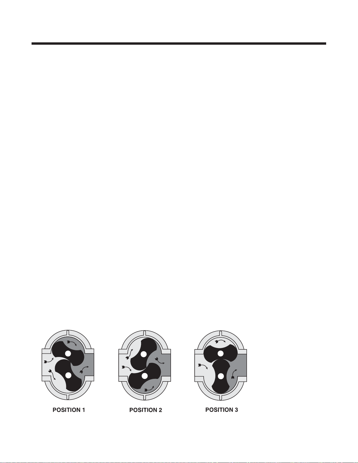
Operation of the familiar basic rotary lobe blower is
illustrated in FIGURE 1, where air flow is left to right
from inlet to discharge with the top impeller rotating
clockwise.In Position 1 it is delivering a known volume
(B) to the discharge, while space (A) between the
lower impeller and cylinder wall is being filled.
Counterclockwise rotation of this impeller then traps
equal volume (A) in Position 2, and further rotation
delivers it to the discharge in Position 3.
One complete revolution of the driving shaft alternately
traps four fixed and equal volumes of air (two by each
impeller) and pushes them through to the discharge.
The volume capacity of a lobe blower operating at a
constant speed therefore remains relatively independent of reasonable inlet of discharge pressure variations.
To change capacity, it is necessary either to change
speed of rotation or blow off some of the discharge air.
No attempt should ever be made to control capacity
by means of a throttle valve in the intake or discharge
piping.This will not only increase the power load on the
driver, but can also overload and seriously damage the
blower.If a possibility does exist that flow to the blower
inlet may be cut off during normal operation of a
process, then an adequate vacuum relief valve must
be installed near the blower. A pressure type relief
valve in the discharge line near the blower is required
for protection against cut-off or blocking in this line.
Refer to FIGURE 3 for a complete piping schematic.
When a belt drive is installed, blower speed can usually
be adjusted to obtain desired capacity by changing the
diameter of one or both sheaves.In a direct coupled
arrangement a variable speed motor or transmission
is required, or excess air may be blown off through
a manually controlled unloading valve and silencer.
If returned to the blower inlet, the air must be cooled
to 100°F (38°C) through a by-pass arrangement to
maintain acceptable blower temperatures.
Before making any change in blower capacity, or
operating conditions, contact ROOTS for specific
information applying to your particular blower. In all
cases, operating conditions must be maintained within
the approved range of pressures, temperatures and
speeds as stated under
LIMITATIONS. The air blower
must not be used to handle liquids or solids as serious
damage to the rotating parts may result.
FIGURE 1 – FLOW THROUGH A BASIC ROTARY LOBE BLOWER
A
B
A
B
A
B
Page 10

9
©2002 Dresser, Inc.all rights reser ved.
ROOTS, RAM, URAI and WHISPAIR are trademarks of Dresser, Inc.
Dresser Design and Universal RAI are registered trademarks of Dresser, Inc.
TROUBLESHOOTING
Trouble Item Possible Cause Remedy
No flow 1 Speed too low Check by tachometer and compare with published
performance
2Wrong rotation Compare actual rotation with Figure 1 or 2
Change driver if wrong
3 Obstruction in piping Check piping, valves, silencer to assure open flow path
Low capacity 4 Speed too low See item 1, If belt drive, check for slippage and readjust
tension
5 Excessive pressure rise Check inlet vacuum and discharge pressure and compare
with Published performance
6 Obstruction in piping See item 3
7 Excessive slip Check inside of casing for worn or eroded surfaces causing
excessive clearances
Excessive power 8 Speed too high Check speed and compare with published performance
9 Excessive pressure rise See Item 5
10 Impeller rubbing Inspect outside of cylinder for high temperature areas, then
check for impeller contact at these points.Correct blower
mounting, drive alignment
11 Scale, sludge, rust Clean blower appropriately
or product build up
Overheating of 12 Inadequate lubrication Check oil sump levels in gear and drive end headplates
bearing or gears 13 Excessive lubrication Check oil levels. If correct, drain and refill with clean oil of
recommended grade
14 Excessive pressure rise See Item 5
15 Coupling misalignment Check carefully. Realign if questionable
16 Excessive belt tension Readjust for correct tension
Vibration 17 Misalignment See Item 15
18 Impellers rubbing See Item 10
19 Worn bearings/gears Check gear backlash and condition of bearings, and replace
as indicated
20 Unbalanced or rubbing Scale or process material may build up on casing and
impeller impellers, or inside impellers.Remove build-up to restore
original clearances and impeller balance
21 Driver or blower loose Tighten mounting bolts securely
22 Piping resonances Determine whether standing wave pressure pulsations are
present in the piping
23 Scale/sludge build-ups Clean out inter ior of impeller lobes to restore dynamic
balance
24 Casing strain re-work piping alignment to remove excess strain
Driver stops, or 25 Impeller stuck Check for excessive hot spot on headplate or cylinder.
will not start See item 10. Look for defective shaft bearing and/or
gear teeth
26 Scale, sludge, rust or Clean blower appropriately
product build-up
Excessive breather 27 Broken seal Replace seals
Blow-by or excessive 28 Defective O-ring Replace seals and O-ring
oil leakage to vent area
Page 11

10For your nearest ROOTS Office, dial our Customer Service Hot Line 1 877 363 ROOTS (7668).
MAINTENANCE & REPLACEMENTS:UNIVERSAL RAI
®
SERIES BLOWERS
A good program of consistent inspection and maintenance is the most reliable method of minimizing repairs
to a blower. A simple record of services and dates will
help keep this work on a regular schedule.Basic
service needs are:
• Lubrication
• Checking for hot spots
• Checking for increases or changes in vibration
and noise
• Recording of operating pressures and temperatures
Above all, a blower must be operated within its
specified rating limits, to obtain satisfactory service life.
A newly installed blower should be checked often
during the first month of full-time operation. Attention
thereafter may be less frequent assuming satisfactory
performance. Lubr ication is normally the most important consideration and weekly checks of lubricant
levels in the gearbox and bearing reservoirs should
be customary. Complete oil change schedules are
discussed under
LUBRICATION.
Driver lubrication practices should be in accordance
with the manufacturer’s instructions. If direct connected
to the blower through a lubricated type coupling, the
coupling should be checked and greased each time
blower oil is changed.This will help reduce wear and
prevent unnecessary vibration.In a belted drive
system, check belt tension periodically and inspect
for frayed or cracked belts.
In a new, and properly installed, unit there is no contact
between the two impellers, or between the impellers
and cylinder or headplates.Wear is confined to the
bearings (which support and locate the shafts) the oil
seals, and the timing gears.All are lubr icated and wear
should be minimal if clean oil of the correct grade is
always used.Seals are subject to deterioration as well
as wear, and may require replacement at varying periods.
Shaft bearings are designed for optimum life under
average conditions with proper lubrication and are
critical to the service life of the blower. Gradual
bearing wear may allow a shaft position to change
slightly, until rubbing develops between impeller and
casing.This will cause spot heating, which can be
detected by observing these surfaces.Sudden bearing
failure is usually more serious.Since the shaft and
impeller are no longer supported and properly located,
extensive general damage to the blower casing and
gears is likely to occur.
Oil seals should be considered expendable items, to
be replaced whenever drainage from the headplate
vent cavity becomes excessive or when the blower is
disassembled for any reason.Sealing effectiveness
can vary considerably from seal to seal and is also
affected to surprising degree by shaft finish under the
seal lip.Because of these nor mal variables, minor seal
leakage should not be considered as indicating
seal replacement.
Timing gear wear, when correct lubrication is maintained, should be negligible over a period of years.
Gear teeth are cut to provide the correct amount of
backlash, and gears correctly mounted on the shafts
will accommodate a normal amount of tooth wear
without permitting contact between lobes of the two
impellers. However, too high an oil level will cause
churning and excessive heating.This is indicated by
unusually high temperature at the bottom of the gear
housing. Consequent heating of the gears will result
in loss of tooth-clearance , backlash and rapid wear of
the gear teeth usually will develop. Continuation of this
tooth wear will eventually produce impeller contacts
(knocking), and from this point serious damage will be
unavoidable if blower operation is continued.A similar
situation can be produced suddenly by gear tooth
fracture, which is usually brought on by sustained
overloading or momentary shock loads.
Problems may also develop from causes other than
internal parts failure. Operating clearances within a
blower are only a few thousandths of an inch.This
makes it possible for impeller interference or casing
rubs to result from shifts in the blower mounting, or
from changes in piping support. If this type of trouble
is experienced, and the blower is found to be clean, try
removing mounting strains.Loosen blower mounting
bolts and reset the leveling and drive alignment.Then
tighten mounting again, and make sure that all piping
meets blower connections accurately and squarely
Foreign materials in the blower will also cause trouble,
which can only be cured by disconnecting the piping
and thoroughly cleaning the blower interior.
A wide range of causes & solutions for operating
troubles are covered in theTROUBLE SHOOTING
CHECKLIST.The remedies suggested should be
performed by qualified mechanics with a good
background, using procedures detailed in this manual.
Major repairs generally are to be considered beyond
the scope of maintenance, and should be referred
to ROOTS.
Warranty failures should not be repaired at all, unless
specific approval has been obtained through ROOTS
before starting work. Unauthorized disassembly within
the warranty period will void the warranty.
Page 12

11
©2002 Dresser, Inc.all rights reser ved.
ROOTS, RAM, URAI and WHISPAIR are trademarks of Dresser, Inc.
Dresser Design and Universal RAI are registered trademarks of Dresser, Inc.
It is recommended that major repairs be performed
at an authorized ROOTS facility. However, it is
recognized that this may not always be practical. If a
blower is out of warranty, mechanical adjustments and
parts replacement may be undertaken locally at the
owner’s option and risk. It is recommended that
ROOTS™parts be used to insure fit and suitability.The
maintenance of a small stock of on-hand spare parts
can eliminate possible delays.When order ing parts
give item numbers and their word descriptions from the
appropriate sectional drawings.Also specify quantities
required and the blower model and serial number from
the nameplate.
Repairs or adjustments are best performed by personnel with good mechanical experience and the ability to
follow the instructions in this manual.Some operations
involve extra care, patience, and a degree of precision
work.This is especially true in timing impellers and in
handling bearings. Experience indicates that high
percentages of bearing failures are caused by dirt
contamination before or during assembly. Therefore,
the work area should be cleaned before starting
disassembly, and new or re-usable parts protected
during progress of the work.
In the following repair procedures, numbers shown in
brackets ( ) correspond to the item numbers used
in sectional drawings.It is recommended that the
procedures be studied carefully and completely, wit h
frequent reference to the drawings, before starting
work.This will produce better efficiency through an
understanding of what work is to be done, and the
order of doing it. Before disassembly, mark all parts
so that they may be returned to original locations or
relative positions.
Requirements for special tools will depend on the work
to be done. If impeller clearances and float are to be
checked or re-set, a dial indicator and a set of long
feeler gauges will be needed.Work involving removal
of the timing gears cannot be accomplished without a
suitable puller.
Design of ROOTS
™
blower is simple, and most repair
operations are straightforward.For this reason, the
following procedures are intended mainly to indicate
a preferred work order and to call out points to be
observed.Where special operations are required,
detailed coverage is given.
A – Replacing Timing Gears
1. Drain all oil from the gearhouse by removing drain
plug (21) in the bottom. Remove gearhouse by
taking out all cap screws (23) in its flange.It may
be necessary to bump the sides with a wood block
or mallet to break the flange joint.
2. Reach through one of the blower pipe connections
and place a chalk mark on the strip of one impeller
and the mating waist of the other, so that they
may easily be returned to their original relative
positions.
3. GEAR REMOVAL: CAUTION: Do not remove gear
nuts (17) completely before the gears are unseated
from the taper fits or damage/injury may result.
For this operation, the impellers should be wedged,
as shown in Table 5.Back off gear clamping nuts
(17) about 1/4”. Use a suitable puller or wedge.As
the puller set screw is torqued, the puller will have
a tendency to turn and contact teeth of the other
gear.To prevent this contact, hold the puller corner
nut with a wrench while torquing the set screw.
Once the gear is unseated, remove the puller.
Remove gear nuts (17) and the gear.
4. GEAR INSTALLATION: Place impellers in correct
position as previously marked.Be sure shafts and
gear bores are clean, oil free and free of scratches.
Clean the shaft tapered fits. Place hardwood
wedges as shown in Table 5. Install drive gear
(4) and gear nut (17).Tighten the drive gear nut
to the torque given below. Blower assembly
must be fastened down for torquing operation.
5. Installing driven gear (4) – Inser t a long, metal
feeler gauge between the impellers’lobes at the
fronts or backs as shown below. Feeler
gauge thickness to be a middle value from Table 5
for fronts and backs. Install nut (17).Tighten lightly
with a small wrench, then check front and back
clearances against Table 5 for each 45° position.
Both fronts and backs should be about the same
and within the specified range in Table 5. Adjust
gear position, if necessary, then insert the
corrected feeler gauge and wedges and use a
torque wrench to tighten the gear nut to the torque
specified in below. Remove wedges and rotate
the drive shaft by hand to make sure there are no
gear tight spots or impeller contacts. CAUTION!
Keep fingers away from impellers and gears.
UNIVERAL RAI
®
SERIES BLOWER GEAR NUT TORQUE
Frame Size Torque
lb.-ft. (kg-m)
22, 24, 60 (8.3)
32, 33, 36 110 (15.2)
42, 45, 47 190 (26.3)
53, 56, 59 250 (34.6)
65, 68, 615 400 (55.3)
76, 711, 718 550 (76.1)
Page 13

12For your nearest ROOTS Office, dial our Customer Service Hot Line 1 877 363 ROOTS (7668).
bar with recessed end that will bear on the outer
metal edge of seal enclosure. Seal lip should
point toward the driving tool. Seals to be flush
without board bore face.Apply a light coat of oil or
grease to the seal lips.In a similar fashion, install
lip seals into the drive end headplate.
8. Place cylinder on a flat surface. Assemble gear
end headplate to cylinder after checking flange
punch marks. Drive in the two locating dowel pins
before tightening flange screws.Also install gear
end foot using the same longer cap screws (32)
and washers (41). (On 6” & 7” UNIVERSAL RAI
®
blower install both gear end feet.)
9. Place the assembly horizontally on steel blocks
with gear end headplate on bottom.The height
of the blocks should be sufficient to clear gear
end shaft extensions.Assemble impellers into
the cylinder with the drive shaft (longer shaft)
in same location as in original assembly. Before
starting the shafts through the headplate holes,
make sure shaft ends have no sharp or rough
edges to damage seal lips. Position impellers at
90° to each other in the cylinder, using lobe-andwaist match marks if original impellers are being
re-installed. Install drive end headplate and feet in
same manner as gear end.
10. It is recommended that new bearings be used for
rebuild. Apply thin film of machine oil on the shaft
bearing fit, bearing I.D., and headplate bearing
bore. Install drive end bearings into headplate.
Use a tube with flanged end that will contact both
bearing faces simultaneously. Refer to Assembly
Drawing for proper bearing depths.
NOTE: Cylindrical drive bearing should be
installed with inner race large shoulder
facing outboard.
11. Place blower on its feet on a flat surface.
Loosen feet capscrews (32) and square up unit.
Re-tighten capscrews (32). Clamp unit down to
a solid base for further assembly.
12. Oil the gear end bearing fits as descr ibed
previously. Install 2-1/2” thru 5” blower gear end
bearings flush with the headplate bearing
shoulders using proper drivers.On 6” & 7”
gear diameter units, install thrust washer
(29) in bearing bores then install gear end
bearings so they protrude 1/16” (1.6mm) above
headplate surface.
13. Install bearing clamp plates (34). On 6” & 7”
gear diameter units, blower impeller end
clearances are also to be set during this step.
Install clamp plates (34) with capscrews (31)
making sure that the gap between the clamp plates
and the headplate is even all around.At the same
time, set end clearances per Table 5.
14. Install gears and time impellers as in (A).
6. Check the end clearances between impellers and
headplates. Adjust clearances per B-15 below.
7. When clearances are correct, clean and re-install
the gearhouse. Check condition of flange gasket
(7) and replace if questionable.Fill gearhouse to
correct level with proper grade oil.
B – Replacing Shaft Bearings and Impellers
Remove coupling or sheave from the drive shaft.
Drain and remove gearhouse, and pull the timing
gears. If gears are to be re-used, mark them so
they may be returned to the same shafts.
1. Break cor ners and deburr the keyway. Remove
bearing end cover at the drive end.Remove
bearing clamp plates (34).
2. Make single and double identifying punch marks
on the mating edges of headplate and cylinder
flanges at the two ends of the blower.
3. At the drive end, drive out the two dowel pins and
remove all capscrews holding headplate to
cylinder.By inser ting jacking screws into the two
threaded flange holed, and turning them in evenly,
the headplate will be separated from the cylinder.
As the headplate comes off the shafts it will bring
bearings with it. 2-1/2” and 3-1/2” gear diameter
units do not have tapped holes for jack screws in
the drive end headplates.Remove dowel pins and
all capscrews holding headplate to cylinder and
foot on the drive end.Suppor t unit under gear end
cylinder flange with the shafts vertical. Using soft
metal block against gear end shafts, push them
out of gear end headplate.
4. For 2-1/2” and 3-1/2” gear diameter units, support
the drive end headplate on the underside, and
using soft metal block against drive end shafts,
push them out of drive end headplate.
For 4”, 6” & 7” gear diameter units, from the gear
end, using a wood or soft metal block against the
ends of the shafts, drive them out of the head
plate. If they are to be reused, protect them from
damage in this operation.
5. If blower interior surfaces need cleaning, it may be
advisable to separate the gear end headplate from
the cylinder.Use the same general procedure as
employed at the drive end.
6. Working from the back (flat) face of each head
plate, push or tap out the bearings and seals. Use
a round bar or tube that will pass through the shaft
clearance holes in the headplates.All lip seals will
be damaged during removal and must be
replaced.
7. Clean bearing and seal pockets in headplates and
remove burrs or rough edges. (Apply a thin coating
of sealant on seal O.D.) Press new seals (27) into
gear end headplate using a round tube or
Page 14

13
©2002 Dresser, Inc.all rights reser ved.
ROOTS, RAM, URAI and WHISPAIR are trademarks of Dresser, Inc.
Dresser Design and Universal RAI are registered trademarks of Dresser, Inc.
15. For setting end clearances on 2-1/2” thru 5” gear
diameter units, special tools, thrust adjuster fork
and thrust adjuster saddle are required. Refer to
Table 5 for installation of tools.The flat side of the
saddle rests against the bearing inner race and the
flat side of the fork rests against the back side of
the gear.Install a shim, with thickness equal to
gear end clearance (Table 5), between the impeller
and the gear end headplates.Tap on top of the fork
until the shim becomes snug. Remove the shim
and check end clearances.To increase gear end
clearance, tap on the end of the gear end shaft
with a soft metal mallet. Set end clearances for
6” & 7” by turning capscrews (31) evenly in or out.
16. Install drive end cover (5) after packing bearing
cavities with suitable grease.Replace drive shaft
seal. Lip must point toward (33) the bearing.
Exercise care not to damage the lip as it passes
over shaft keyway.
17. Install gasket item (7). Install the gear house after
cleaning out the inside.Tighten gear box cap
screws (23) evenly. Fill with correct grade of oil
until oil flows out through oil level hole. Grease
drive and bearings. (See Lubrication.)
18. Reinstall coupling or belt sheave making sure that
they have a slight slide fit with the shaft and could
be installed by hand.
discharge gas pressure. Also, there exists a
possibility of gear end oil and drive end grease
leakage into the gas stream.
The lubricants selected must be compatible with the
gas. Mechanical Seal Replacement: Disassemble the
blower.Dur ing disassembly, damage to mechanical
seals is very likely. Dur ing rebuild, always use new
mechanical seals. Prior to any assembly, make sure
that all parts are completely clean and free from nicks
and scratches.
(1) Place head plate on an assembly table with seal
bores pointing up.Coat the OD of the stationar y
seal element and install it with carbon facing up in
the seal bore with a seal driver that is guided by the
bearing bore. Drive the seal flush with front face of
the seal bore. Repeat this procedure for all four
seals. Apply a light coating of lubricating oil on the
sealing surface.Protect sealing faces during
assembly from any damage.
(2) Apply teflon based sealant on the cylinder flanges
before installing head plates.Continue the assembly
procedure as outlined up to bearing installation.
Before installation of the bearings, the seal mating
rings need to be installed. Apply light film of
lubricating oil on mating ring o-rings and sealing
faces.Slide mating rings on the shaft and up to
carbon faces making sure that no damage to the
o-rings occur during installation (break sharp
shaft corners to avoid damage to the o-rings during
initial preparation). Install bearings all the way
against the back bearing bore shoulders.
(3) Complete the rest of the assembly.Make sure all
plugged holes are sealed with teflon thread
liquid sealant.
Note: On 6” gear diameter units, shims (44) are used
between the bearing clamp plates and the head plate
on the gear end.
Also, on size 32 and 42, washers with embedded
o-rings are used on the center head plate to
cylinder bolts.
After the assembly is completed, plug the blower
inlet and discharge connections and run static
soap bubble.Leak test to assure leak
free assembly.
For satisfactory operation of mechanical seals,
synthetic lubricants are recommended (Check
suitability to gases before using.)
Oils:
(1)ROOTS™GT Synthetic Lubricant ROOTS
P/N 13-106-001 (1) one quart ISO-220
(2) Mobil SHC 600 Series Lubricating Oils
Grease:
ROOTS™Synthetic Grease – NLGI # 2
ROOTS P/N T20-019-001 (1) one 14 oz tube
TECHNICAL SUPPLEMENT
for 32, 33, 36, 42, 45, 47, 53, 56, 59, 65, 68, 615
UNIVERAL RAI®-G BLOWERS
ROOTS™Universal RAI™-G rotary positive gas blowers
are a design extension of the basic Universal RAI
™
blower model. URAI™-G blower uses (4) mechanical
seals in place of the standard in board lip seals to
minimize gas leakage into the atmosphere.The seal
vent chambers are plugged.These units are intended
for gases which are compatible with cast iron case
material, steel shafts, 300/400 series stainless steel
and carbon seal components, viton o-rings and the
oil/grease lubricants. If there are any questions
regarding application or operation of this gas blower,
please contact factory.
Precaution: URAI™-G blowers: Care must be used
when opening the head plate seal vent chamber
plugs ( 43) as some gas will escape–if it is a pressure system, or the atmospheric air will leak in-if
the system is under vacuum.There is a possibility
of some gas leakage through the mechanical seals.
This leakage on the gear end will escape through
the gear box vent, and on the drive end, through
the grease release fittings. If the gas leakage is
undesirable, each seal chamber must be purged
with an inert gas through one purge gas hole
(43 ) per seal .There are two plugged purge gas
holes(1/8 NPT) provided per seal.The purge gas
pressure must be maintained one psi above the
Page 15

14For your nearest ROOTS Office, dial our Customer Service Hot Line 1 877 363 ROOTS (7668).
MAINTENANCE & REPLACEMENTS: RAM
™
SERIES BLOWERS
A good program of consistent inspection and maintenance is the most reliable method of minimizing repairs
to a blower. A simple record of services and dates will
help keep this work on a regular schedule.Basic
service needs are:
• Lubrication
• Checking for hot spots
• Checking for increases or changes in vibration
and noise
• Recording of operating pressures and temperatures
Above all, a blower must be operated within its
specified rating limits, to obtain satisfactory service life.
A newly installed blower should be checked often
during the first month of full-time operation. Attention
thereafter may be less frequent assuming satisfactory
performance. Lubr ication is normally the most important consideration and weekly checks of lubricant
levels in the gearbox and bearing reservoirs should
be customary. Complete oil change schedules are
discussed under
LUBRICATION.
Driver lubrication practices should be in accordance
with the manufacturer’s instructions. If direct connected
to the blower through a lubricated type coupling, the
coupling should be checked and greased each time
blower oil is changed.This will help reduce wear and
prevent unnecessary vibration.In a belted drive system, check belt tension periodically and inspect for
frayed or cracked belts.
In a new, and properly installed, unit there is no contact
between the two impellers, or between the impellers
and cylinder or headplates.Wear is confined to the
bearings (which support and locate the shafts) the oil
seals, and the timing gears.All are lubr icated and wear
should be minimal if clean oil of the correct grade is
always used.Seals are subject to deterioration and
wear, and may require replacement at varying periods.
Piston ring seals (28) are designed to operate without
rubbing contact, once temperature and thermal growth
have stabilized.The stationary rings will rub the rotating
sleeve (38) briefly as a result of temperature cycles
that occur during the startup and shutdown of the unit.
The sleeves are hardened and the rings are coated
with dry lubricant that provides for temporary break in
wear. Replace piston ring seals if they become excessively worn or inspection shows more than .010”
(.25mm) axial clearance between ring and groove.
Shaft bearings are designed for optimum life under
average conditions with proper lubrication and are
critical to the service life of the blower. Gradual bearing
wear may allow a shaft position to change slightly, until
rubbing develops between impeller and casing.This
will cause spot heating, which can be detected by
observing these surfaces. Sudden bearing failure is
usually more serious. Since the shaft and impeller are
no longer supported and properly located, extensive
general damage to the blower casing and gears is
likely to occur.
Oil seals should be considered expendable items, to
be replaced whenever drainage from the headplate
vent cavity becomes excessive or when the blower is
disassembled for any reason.Sealing effectiveness
can vary considerably from seal to seal and is also
affected to surprising degree by shaft finish under the
seal lip.Because of these nor mal variables, minor
seal leakage should not be considered as indicating
seal replacement.
Timing gear wear, when correct lubrication is maintained, should be negligible over a period of years.
Gear teeth are cut to provide the correct amount of
backlash, and gears correctly mounted on the shafts
will accommodate a normal amount of tooth wear
without permitting contact between lobes of the two
impellers. However, too high an oil level will cause
churning and excessive heating.This is indicated by
unusually high temperature at the bottom of the gear
housing. Consequent heating of the gears will result in
loss of tooth-clearance , backlash and rapid wear of the
gear teeth usually will develop. Continuation of this
tooth wear will eventually produce impeller contacts
(knocking), and from this point serious damage will be
unavoidable if blower operation is continued.A similar
situation can be produced suddenly by gear tooth
fracture, which is usually brought on by sustained
overloading or momentary shock loads.
Problems may also develop from causes other than
internal parts failure. Operating clearances within a
blower are only a few thousandths of an inch.This
makes it possible for impeller interferences or casing
rubs to result from shifts in the blower mounting, or
from changes in piping support. If this type of trouble
is experienced, and the blower is found to be clean, try
removing mounting strains.Loosen blower mounting
bolts and reset the leveling and drive alignment.Then
tighten mounting again, and make sure that all piping
meets blower connections accurately and squarely
Foreign materials sucked into the blower will also
cause trouble, which can only be cured by disconnecting the piping and thoroughly cleaning the blower interior.
A wide range of causes & solutions for operating
troubles are covered in the TROUBLE SHOOTING
CHECKLIST.The remedies suggested should be
performed by qualified mechanics with a good
background, using procedures detailed in this manual.
Major repairs generally are to be considered beyond
the scope of maintenance, and should be referred
to ROOTS.
Warranty failures should not be repaired at all, unless
specific approval has been obtained through a Sales
Office or the factory before starting work. Unauthorized
disassembly within the warranty period will void the
warranty.
Page 16

15
©2002 Dresser, Inc.all rights reser ved.
ROOTS, RAM, URAI and WHISPAIR are trademarks of Dresser, Inc.
Dresser Design and Universal RAI are registered trademarks of Dresser, Inc.
It is recommended that major repairs be performed at
an authorized ROOTS facility. However, it is recognized
that this may not always be practical. If a blower is
out of warranty, mechanical adjustments and parts
replacement may be undertaken locally at the owner’s
option and risk. It is recommended that ROOTS™parts
be used to insure fit and suitability.The maintenance
of a small stock of on-hand spare parts can eliminate
possible delays.When order ing parts give Item
numbers and their word descriptions from sectional
drawings and parts lists. Also specify quantities
wanted and the blower size and serial number from
the nameplate.
Repairs or adjustments are best performed by
personnel with good mechanical experience and the
ability to follow the instructions in this manual.Some
operations involve extra care, patience, and a degree
of precision work.This is especially true in timing
impellers and in handling bearings. Experience
indicates that high percentages of bearing failures
are caused by dirt contamination before or during
assembly. Therefore, the work area should be cleaned
before starting disassembly, and new or re-usable
parts protected during progress of the work.
In the following repair procedures, numbers shown
in brackets ( ) correspond to the Item numbers
used in assembly drawings, and parts lists.It is
recommended that the procedures be studied carefully
and completely, with frequent reference to the drawings, before starting work.This will produce better
efficiency through an understanding of what work is to
be done, and the order of doing it. Before disassembly,
mark all parts so that they may be returned to original
locations or relative positions.
Requirements for special tools will depend on the work
to be done. If impeller clearances and float are to be
checked or re-set, a dial indicator and a set of long
feeler gauges will be needed.Work involving removal
of the timing gears cannot be accomplished without a
puller suitable.Heat must be used during bear ing and
sleeve installation.
Design of ROOTS
™
blower is simple, and most repair
operations are straightforward.For this reason, the
following procedures are intended mainly to indicate
a preferred work order and to call out points to be
observed.Where special operations are required,
detailed coverage is given.
DISASSEMBLY OF DRIVE END
1. Remove the sheave or coupling and key from the
drive shaft. File off any burrs or sharp edges along
the keyway.
2. Drain oil by removing drain plug (22).
3. Remove the flange screws (75).Tap the drive end
cover to loosen it, then slide it along the shaft care
fully to avoid damaging the lip seal (33) on the
drive shaft keyway. Remove the gasket (7).
Remove oil slinger (40) and cap screw (60).
4. Remove bearing clamp plates (34) by unscrewing
capscrews (32) and removing lock washers (35).
Keep shim halves (10) together exactly as removed
by tagging them with each clamping plate.
5. Remove the headplate – remove all capscrews
(23) holding headplate to the cylinder.Inser t
jacking screws into the four threaded flange
holes and turn them in evenly. The headplate will
separate from the cylinder.The lip seals (27), and
bearing outer race and rollers, are removed with
the headplate and can be pressed out later.
6. Remove the bearing inner race and sleeve (38)
from the shaft with aid of a bearing puller by
inserting the puller jaws in the groove in the sleeve
and applying the jacking screw against the end of
the shaft. Protect the threaded hole and the end
of the shaft with a small, flat spacer between the
shaft and the puller.
DISASSEMBLY OF GEAR END
1. Drain oil completely from the gearbox sump by
removing plugs (22) in bottom of the headplate (1).
2. Loosen all flange screws (75) in the gearbox and
remove all but two upper screws. Bump the gear
box to break the joint if it cannot be pulled free by
hand, then remove the last two screws and lift off
the gearbox.Remove gasket (7).
3. Removing gears: CAUTION: Do not remove gear
nuts (31) completely before the gears are unseated
from the taper fits or damage/injury may result.
Be sure that each gear is marked for return to the
same shaft in the same angular position and that
the gears have match marks for the teeth.For this
operation, the impellers should be wedged as
shown in Figure 8. Back off nuts (31) and slinger
(46).The timing gears (4) have two 1/2” – 13 holes
for pulling purposes.Use a suitable puller.
4. Remove bearing clamp plates (54) by unscrewing
capscrews (32) and removing lock washers.
Group the shims (10), the wavy spring washers
(29) with each clamp plate and tag for ease of
reassembly.
5. Remove the headplate – remove all capscrews
23) holding the headplate to the cylinder.Inser t
jacking screws into the four (4) threaded flange
holes and turn them in evenly. They headplate will
separate from the cylinder.The lip seals (27), and
bearing outer race and rollers, are removed with
the headplate and can be pressed out later.
For RAM™-J WHISPAIR™gas pump units:
The gear end headplate which is removed next
requires a different approach from the drive end.
On this end, the shafts are forced from the bearing
bore by using a bar across the end of the shaft
with threaded rods to the headplate. Once the
headplates are removed from the assembly, the
seal housings can be pressed or driven from
Page 17

16For your nearest ROOTS Office, dial our Customer Service Hot Line 1 877 363 ROOTS (7668).
the headplate bores. Generally, new seals will be
required prior to reassembly.
6. Remove the bearing inner race and sleeve (38)
from the shaft with the aid of a bearing puller by
inserting the puller jaws in the groove in the sleeve
and applying the jacking screw against the end of
the shaft. Protect the threaded hole and the end
of the shaft with a small, flat spacer between the
shaft and the puller.
ASSEMBLY
Prior to any assembly operation, it is essential that all
parts are completely clean and free from nicks and
scratches.
Prior to assembly, lightly coat the groove in the sleave
with slip plate. ROOTS P/N813-314-000.
1. Assembly of Piston ring seals (28) – To avoid
scratching the lip seal surface, install the Piston
ring seals (28) in the sleeves (38) from the end
nearest the groove before assembling the sleeve
on the shaft.
Unhook the gap joint and expand the ring while
sliding it to the groove, then compress it so one
end of the hook joint slides over the other. Move
the ring in the groove to be sure it is free.
NOTE: Care must be taken not to scratch or dent
the sleeve surface since it is the sealing surface
for the lip seal.
2. Installation of sleeves (38) – heat the sleeve to
300° F. (149°C) then quickly slide it on the shaft
tightly against the impeller.If the sleeve hangs up
during assembly, it can be pressed into place
using a tubular pressing tool with square,
clean ends.
3. Assembly of seals (27) in headplate (1) – Place
headplate flat with seal bores up.Be sure the
pressing tool face is clean and square and there is
a smooth, clean entering bevel in the headplate.
Lubricate the seal lips. Place seal over the bore
with lip facing up, then press the seal evenly until it
is flush with bore face.
For Gas Sealed Units: Assemble mechanical
seals (27) in headplate – (CAUTION: Care must
be used to avoid damaging the carbon face.
Before proceeding with this step, you should have
a piloted seal driver which is designed to clear
the carbon face.) with headplate positioned
horizontally with seal bores up.Be sure the
pressing tool face is clean and square and there is
a smooth, clean entering bevel in the headplate.
Place the seal over the bore with carbon facing up.
Then press the seal evenly on its steel shell using
the piloted seal driver until the driver seats against
the stop.
4. Assembly of impellers (12 and 13) to headplate
(1) – Place gear end headplate flat on 3 in.
(76 mm) blocks with the smallest bores facing up.
Inspect entering bevels to be sure they are smooth
and clean. Locate the drive impeller correctly
(top for vertical units and toward the driver for
horizontal units). Place the seal ring gaps toward
the inlet for pressure applications and towards dis
charge for vacuum applications. Insert the impeller
shafts in the headplate so the impellers rest on
the headplate. Use care to avoid damaging the
lip seals.
5. Assembly of cylinder (11) to gear end headplate
(1) – Install dowel pins (16) and secure cylinder to
headplate with capscrews (23).Torque to 35 ft.-lbs
(4.5 Kg-m).Then, install drive end headplate (1)
and dowel pins (16) and secure with capscrews
(23). Install feet (76) & 77) to both headplates and
secure with capscrews (66).Torque to 35 ft.-lbs.
(4.5 kg-m).
For Gas Sealed Units: Use a Teflon sealant
between headplate and cylinder joint. Assemble
rotating seal – apply a light coating of oil to the
O-ring and seal face.Then with flute side out
install the rotating seat tight to the shaft sleeve.
Check and record seal compression – With the
seal body in place and the impeller against the
opposite headplate, check that seal compression
is adequate.This can be checked using a depth
gauge or dial indicator from the face of the head
plate to the face of the mating ring. First, measure
this distance while the carbon is out at its full
length.Then, push the mating ring back against its
stop and measure it again.The difference
between these measurements is the compression.
This can be done easily with finger pressure as the
spring force is only 10 lbs.The correct travel is
given below (record actual compression on
clearance sheets).
SEAL COMPRESSION
Frame Minimum Maximum
400 .047” .097”
600 .108” .151”
* Prior to to assembly, lightly coat the groove in the sleave(38) with slip plate.
ROOTS
™
P/N 813-314-000
6. Installation of bearings (14) – Heat bear ing inner
race to 300°F (149°C) in an oven or hot oil;then
slide it onto the shaft so the bearing shoulder is
snugly against the sleeve. Note: Be sure to install
the shaft shim (70) behind the shaft sleeve before
installing the drive end drive bearing inner race.
This is required to compensate for the oil leader for
shimming. Insert the bearing outer race and rollers
in each bore and tap lightly in place. Spray
bearings with lubricant.
7. Measure and record the end clearances between
the impellers and drive headplate using long feeler
gauges.Then, subtract the allowed average drive
end clearance.See Table 6. The result is the
space required between clamping plates (34) and
bearing outer race. Place shims (10) as required
to get this clearance.Then, fasten the clamping
Page 18

17
©2002 Dresser, Inc.all rights reser ved.
ROOTS, RAM, URAI and WHISPAIR are trademarks of Dresser, Inc.
Dresser Design and Universal RAI are registered trademarks of Dresser, Inc.
plates to the headplate with capscrews (32) and
lock washers (35).
8. Installation of gear end bearings (14) – Turn the
blower so that the gear end headplates is up. Heat
bearing inner race to 300°F (149°C) in an oven or
hot oil; then slide it onto the shaft so that the
bearing shoulder is snugly against the sleeve.
Insert the bearing outer race and rollers in each
bore and tap lightly into place.
9. Measure and record the end clearance between
the impellers and gear end headplate, then subtract the allowed average gear end clearance.See
Table 6.The result is the space required between
clamping plate (54) and bearing outer race. Place
shims (10) as required to get this clearance.Then
fasten the clamping plates (54) to the headplate
using capscrews (32) and lock washers (35).Do
not install wavy-spring washers (29) at this time,
as a final check of clearances is required first.
10. Final check of end clearances and float – Using
long feeler gauges, check the clearance between
the impellers and drive end headplate.See Table
6. Place the blower assembly on its feet and
correct shimming as required.Then, force the
impellers as close to the gear end headplate as
possible, and check the clearance between
impellers and gear end headplate for agreement
with Table 6. Adjust shimming on the gear end as
required.With unit securely fastened down, use a
dial indicator to measure the impeller float. Again
push the impeller to one end of the cylinder.With
indicator firmly mounted, place contact point on the
end of the shaft just pushed and set dial on zero.
Force the impeller to the opposite end (toward
indicator). Indicator reading will be a measurement
of the impeller float. Repeat process on second
impeller and compare float to Table 6. Adjust
shimming at bearing clamp plates to obtain both
float and end clearances specified in Table 6.
Finally, after clearances and float have been
corrected and checked, remove the gear end
clamping places (54) and install wavy-spring
washers (29) and reinstall shims (10) and clamping
plates (54). Be sure oil feed grooves are up and
toward bearings.
11. Installing drive gear (4) – Be sure shafts and gear
bores are clean and free of scratches.Oil gear nut
threads lightly. Place hardwood wedges as shown
in Figure 8. Install gear (4) and nut (31) so match
mark at the tooth is at the line of engagement.
Tighten the drive gear to the torque given below.
Blower assembly must be fastened down for
torquing operation.
12. Left side discharge machine
Installing driven gear (14) – Insert a long metal
feeler gauge between the impellers’lobes at the
fronts as shown in Table 6.Feeler gauge thickness
to be a middle value from Table 6 for fronts.
13. Right side discharge machine
Installing driven gear (4) – Insert a long metal
feeler gauge between the impellers’lobes at the
backs.Feeler gauge thickness to be minimum
value from Table 6 for backs.
RAM
™
SERIES BLOWER GEAR NUT TORQUE
Frame Size Torque
lb.-ft. (kg-m)
404, 406, 409, 412, 418 400 (56)
616, 624 630 (88)
RAM
™
SERIES BLOWER OIL SLINGER SCREW TORQUE
Frame Size Torque
lb.-ft. (kg-m)
404, 406, 409, 412, 418 75 (10)
616, 624 140 (19)
Align the gear so the tooth match marks agree with
the drive gear, then install slinger (46) and nuts (31).
Tighten lightly with a small wrench, then check front
and back clearances against Table 6 for each 45°
position. Both fronts should be about the same and
backs should about equal and be within the specified
range in Table 6.Adjust gear position if necessar y, then
insert the corrected feeler gauge and wedges and use
a torque wrench to tighten the gear nut to the torque
specified above.Remove wedges and rotate the drive
shaft by hand to make sure there are no gear tight
spots or impeller contacts. CAUTION: Keep
fingers away from impeller end gears.
Install gearbox (3) with gasket (7) and tighten the
capscrews (75) evenly to 10 ft.-lbs. (1.3 kg-m).
Install drive end oil slinger (40) and capscrew
(60), apply Locktite to threads and torque to value
specified above.
Install drive end cover (5) and gasket (7) with drive lock
pins (17) in place, being careful not to dent or scratch
drive shaft lip seal surface.Tighten capscrews (75)
evenly. Check seal bore for concentricity with shaft
using an indicator; reposition drive lock pins, if necessary. Install seal (33) with lip facing inward, using care
to avoid tearing or scratching seal on shaft keyway. Use
a pressing tool with clean, square ends to insure correct positioning of the seal. For hydrodynamic style
seals, the shaft rotation is critical for correct installation
and proper sealing. Match the directional arrow shown
on the seal faces with the required shaft rotation.An
installation protective sleeve is required to protect seal
lip during installation.
Install vent plug (21) in each headplate.
Replace oil drain plugs (22) and refill drive end and
gear sumps with proper grade of oil as discussed
under
LUBRICATION.
Install drive sheave or coupling half and install blower,
refer to
INSTALLATION instructions.
Page 19
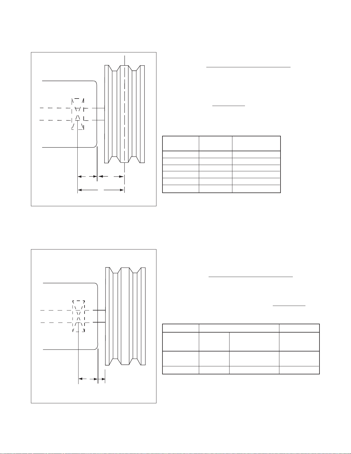
18For your nearest ROOTS Office, dial our Customer Service Hot Line 1 877 363 ROOTS (7668).
ALLOWABLE OVERHUNG LOADS FOR V-B ELT DRIVES UNIVERSAL RAI®/URAI™-JUNITS
Belt Pull lbs =
252100 • Motor HP
Blower RPM • Sheave Diameter
B = (1/8” + )
Sheave Width
2
Frame Dimension Max Allowable
Size “A” Shaft Load (lb-in.)
22, 24 0.61 80
32, 33, 36 0.80 300
42, 45, 47 1.02 640
53, 56, 59 1.13 1,110
65, 68, 615 1.36 1,550
76, 711, 718 1.16 2,300
NOTE: Arc of sheave belt contact on the smaller sheave not to be less than 170°
Driver to be installed on the inlet side for vertical units, and on the drive shaft side
for horizontal units.
ALLOWABLE OVERHUNG LOADS FOR V-B ELT DRIVES 400 - 600 RAM
™
UNITS
Belt Pull lbs =
27500 • Motor HP
Blower RPM • Sheave Diameter
Shaft Load (lb.in) = Belt Pull • (A + 1/8” + )
Sheve Width
2
Max Allowable
Frame Standard Bottom Drive or Shaft Load
Size Unit Double Shaft Seal (lb-in.)
404, 406 1.90 2.11 3,200
409, 412, 418 1.90 2.11 3,200
616, 624 2.11 2.67 7,975
Dimension “A”
NOTE: Arc of sheave belt contact on the smaller sheave not to be less than 170°
Driver to be installed on the inlet side for vertical units, and on the drive shaft side for
horizontal units.
C = Distance between drive bearing center line and
sheave center line (A+B)
Shaft Load (lb.in) = Belt Pull • C
FIGURE 2
A
B
C
A
1/8" Max
Page 20
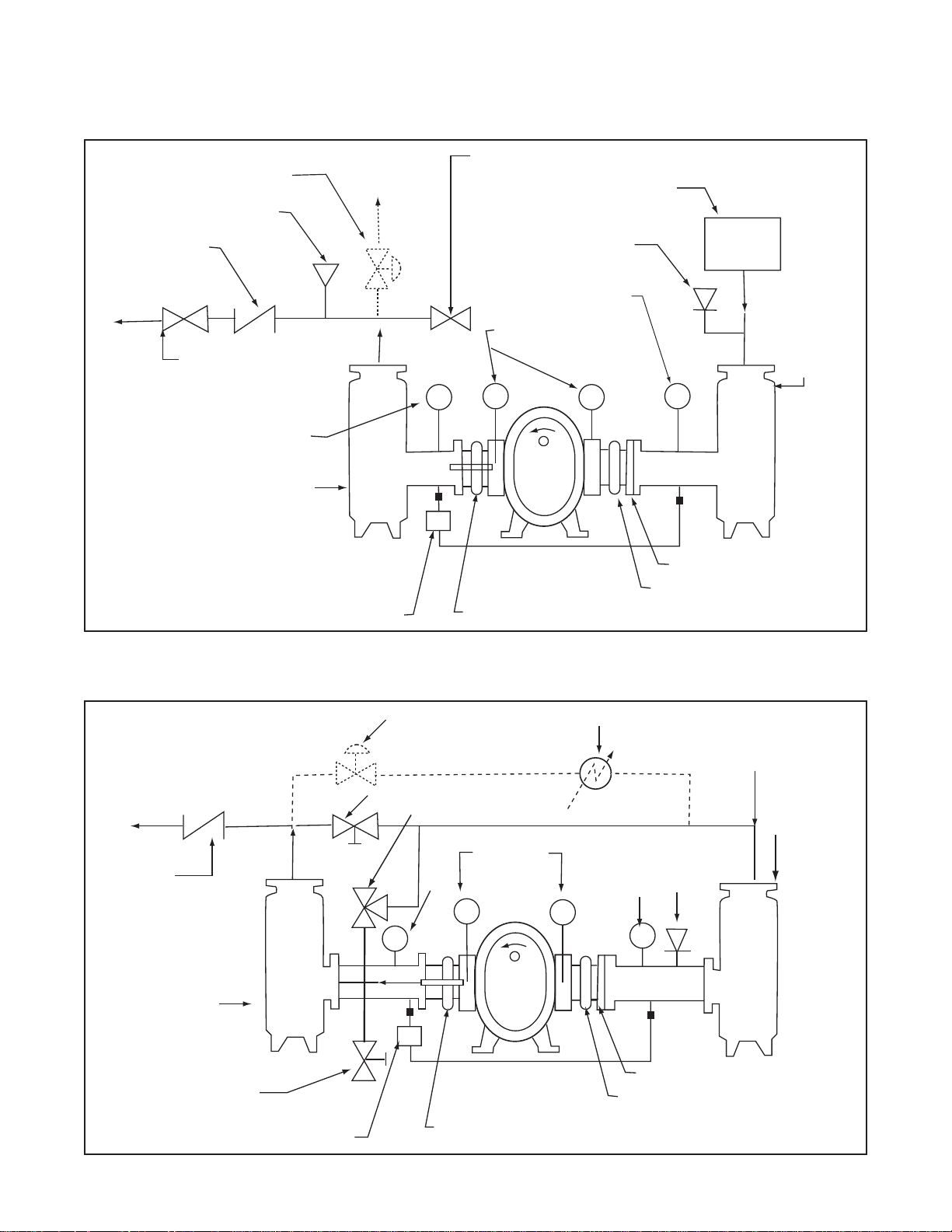
19
©2002 Dresser, Inc.all rights reser ved.
ROOTS, RAM, URAI and WHISPAIR are trademarks of Dresser, Inc.
Dresser Design and Universal RAI are registered trademarks of Dresser, Inc.
AIR BLOWER INSTALLATION WITH ACCESSORIES
Above are suggested locations for available accessories.
GAS BLOWER INSTALLATION WITH ACCESSORIES
Above are suggested locations for available accessories.
FIGURE 3
Back Pressure
Regulator (optional)
Pressure Relief Valve
Check V alve
Isolation Valv e
with Limit Switch
Temperature Gauge
Discharge Silencer
*Differential Pressure &
Temperature Switches
Manual Discharge Unloading Valve
Inlet Air FIlter
Vacuum Relief Valve
Temperature Gauge
Manometers
AIR BLOWER
Expansion Joint with Control Unit
Inlet
Silencer
Temporary Screen
Expansion Joint
Back-Pressure
Regulator
Normal Starting Valve
Pressure Relief Valve
Check
Valve
Discharge
Silencer
Temporary
Starting Valve
Temperature
Gauge
Pressure
Gauge
GAS BLOWER
By-Pass Cooler
Temperature
Gauge
Temporary Screen
Expansion Joint
Vacuum
Relief
Valve
Inlet
Silencer
Differrential Pressure &
Temperature Switches
Expansion Joint with Control Unit
Page 21
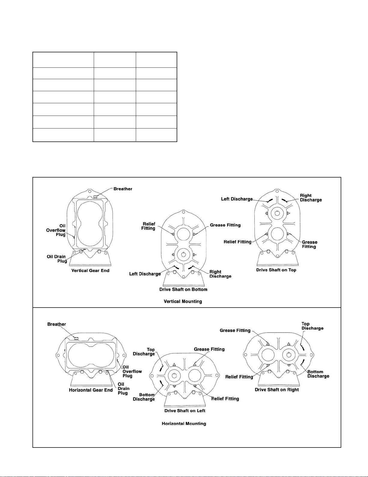
For your nearest ROOTS Office, dial our Customer Service Hot Line 1 877 363 ROOTS (7668).
BLOWER ORIENTATION CONVERSION
20
Model Reversible Whispair
Rotation Design
Universal RAI yes no
URAI-J no yes
URAI-G yes no
RAM yes no
RAM-J no yes
RAM-GJ no yes
BLOWER ORIENTATION AND LUBRICATION POINTS:UNIVERSAL RAI®& URAI™-G GAS BLOWERS
Special Note: WHISPAIR™models are designed to
operate with only one shaft rotation direction to take
full advantage of the Whispair feature.Therefore, a
WHISPAIR™blower should be operated in the following
combinations only.
• CCW Rotation: Bottom Shaft; Right side discharge
or a Left Shaft; Bottom discharge
• CCW Rotation: Top Shaft; Left side discharge or a
Right Shaft;Top discharge
•
CW Rotation: Bottom Shaft; Left side discharge or
a Right Shaft Bottom discharge
• CW Rotation: Top Shaft; Right side discharge or a
Left Shaft Top discharge
FIGURE 4
Page 22
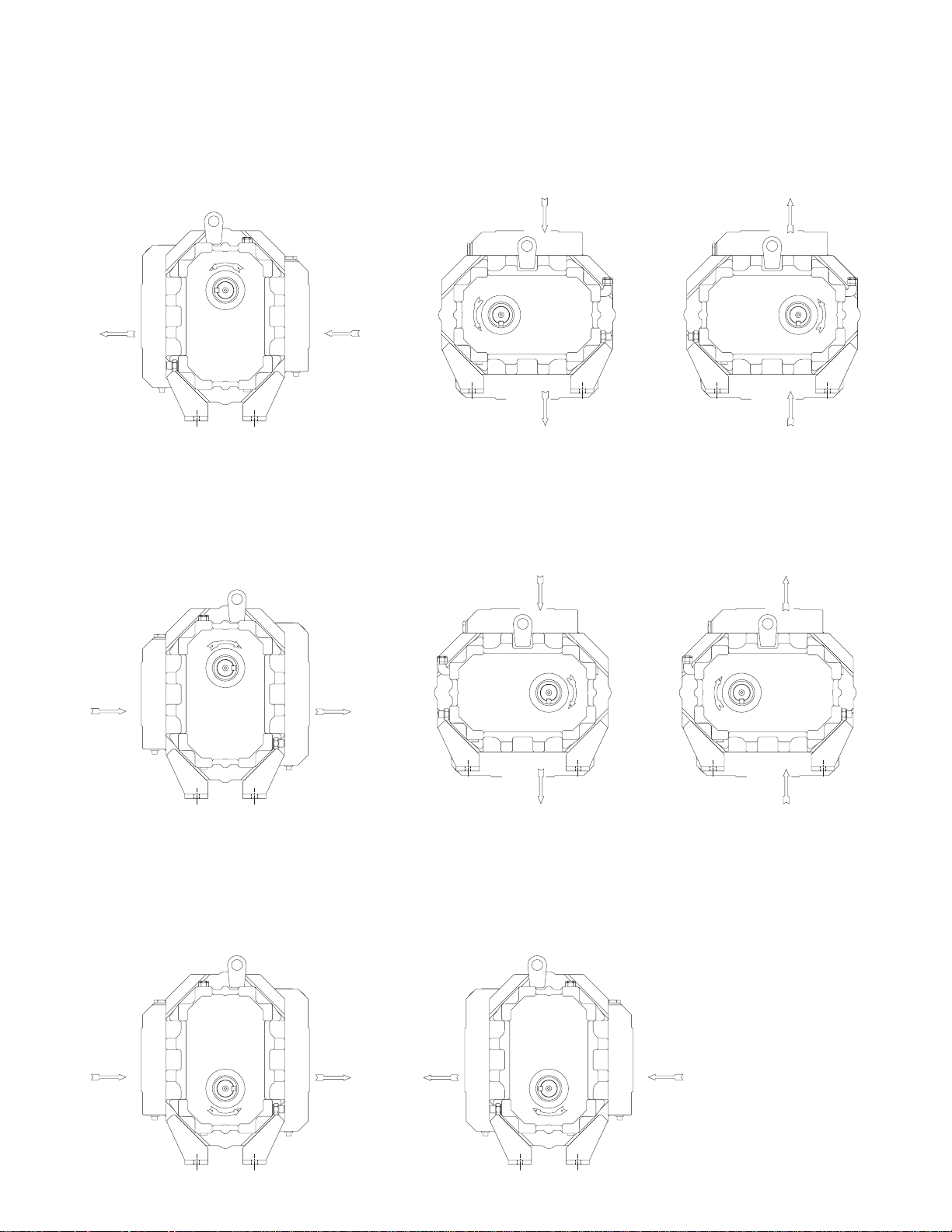
21
©2002 Dresser, Inc.all rights reser ved.
ROOTS, RAM, URAI and WHISPAIR are trademarks of Dresser, Inc.
Dresser Design and Universal RAI are registered trademarks of Dresser, Inc.
BLOWER ORIENTATION CONVERSION - WHISPAIR
™
UNITS
TOP DRV, L.S. DISCH
INLET
DISCH
L.H. DRV, BTM DISCH
INLET
DISCH
INLET
DISCH
DISCH
INLET
CW
TOP DRV, R.S. DISCH
R.H. DRV, TOP DISCH
CCW
CCW
CW
DISCH
INLET
CCW
INLET
DISCH
R.H. DRV, BTM DISCH L.H. DRV, TOP DISCH
DISCH
INLET
CW
BTM DRV, R.S. DISCH BTM DRV, L.S. DISCH
1. STANDARD ARRANGEMENT ( 3-WAY UNIVERSAL)
EXTERNAL SIGHT GLASSES (37) & BREATHERS (21) MUST BE RELOCATED AS SHOWN.
FEET (76&77) & LIFTING LUGS (63) MUST BE RELOCATED AS SHOWN.
CCW
DISCH
INLET
CW
3. BOTTOM DRIVE SHAFT ARRANGEMENT "SPECIAL ORDER" (3-WAY UNIVERSAL)
SPECIAL OGE OIL SLINGER REQUIRED FOR ASSEMBLY.
MAY BE CONVERTED TO HORIZONTAL CONFIGURATION AS PREVIOUSLY SHOWN.
2. NON-STANDARD ARRANGEMENT ( 3-WAY UNIVERSAL)
CYLINDER (11) MUST BE UNBOLTED FROM HEADPLATES (1) AND DISCHARGE
RELOCATED AS SHOWN.
MUST HAVE AUTHORIZATION FOR CONVERSION
SO NOT TO VOID WARRANTY.
EXTERNAL SIGHT GLASSES (37) & BREATHERS (21) MUST BE RELOCATED ALSO.
FEET (76&77) & LIFTING LUGS (63) MUST BE RELOCATED AS SHOWN
FIGURE 5
Page 23

22For your nearest ROOTS Office, dial our Customer Service Hot Line 1 877 363 ROOTS (7668).
URAI™-J WHISPAIR™& URAI™-G GAS BLOWER, MAXIMUM ALLOWABLE OPERATING CONDITIONS
22 2.5 5275 225 (125) 12 (227) 15 (500)
24 2.5 5275 210 (117) 7 (483) 15 (500)
32 3.5 3600 240 (133) 15 1034 16 (539)
33 3.5 3600 225 (125) 12 (827) 15 (500)
36 3.5 3600 225 (125) 7 (483) 15 (500)
42 4.0 3600 240 (133) 15 (1034) 16 (539)
45 4.0 3600 225 (125) 10 (690) 16 (539)
47 4.0 3600 225 (125) 7 (483) 15 (500)
53 5.0 2850 225 (125) 15 (1034) 16 (539)
56 5.0 2850 225 (125) 13 (896) 16 (539)
59 5.0 2850 225 (125) 7 (483) 15 (500)
65 6.0 2350 250 (130) 15 (1034) 16 (539)
68 6.0 2350 240 (133) 14 (965) 16 (539)
615 6.0 2350 130 ( 72) 7 (483) 12 (405)
76 7.0 2050 250 (139) 15 (1034) 16 (539)
711 7.0 2050 225 (125) 10 (690) 16 (539)
718 7.0 2050 130 ( 72) 6 (414) 12 (405)
Frame Gear Speed Temp. Rise Delta Pressure Inlet Vacuum
Size Diameter (Inch) RPM F° (C°) PSI (mbar) INHG (mbar)
404 4.5 4000 240 (133) 18 (1241) 16 (539)
406 4.5 4000 240 (133) 18 (1241) 16 (539)
409 4.5 4000 240 (133) 18 (1241) 16 (539)
412 4.5 4000 240 (133) 15 (1034) 16 (539)
418 4.5 4000 240 (133) 10 (690) 16 (539)
616 6.0 3000 230 (128) 15 (1034) 16 (539)
624 6.0 3000 230 (128) 10 (690) 16 (539)
RAM™, RAM™-J WHISPAIR
™
BLOWER, RAM
™
-GJ GAS BLOWER
MAXIMUM ALLOWABLE OPERATING CONDITIONS
Frame Gear Speed Temp. Rise Delta Pressure Inlet Vacuum
Size Diameter (Inch) RPM F° (C°) PSI (mbar) INHG (mbar)
TABLE 1 -
Page 24
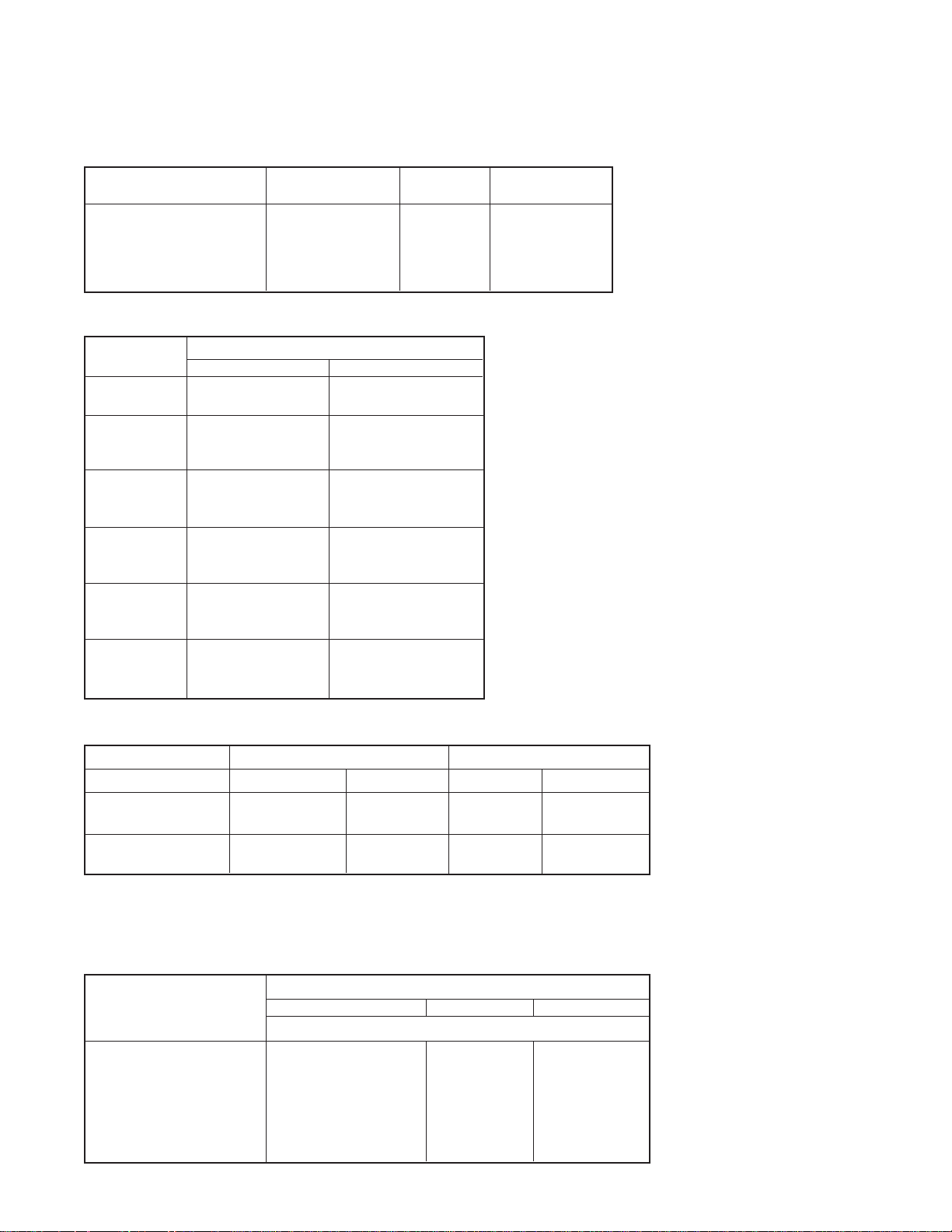
23
©2002 Dresser, Inc.all rights reser ved.
ROOTS, RAM, URAI and WHISPAIR are trademarks of Dresser, Inc.
Dresser Design and Universal RAI are registered trademarks of Dresser, Inc.
RECOMMENDED OIL GRADES
Ambient Viscosity Range ISO No. Approximate
Temperature
°F (°C) SSU at 100°F SAE No.
Above 90° (32°) 1000-1200 320 60
32° to 90° (0° to 32°) 700-1000 220 50
0° to 32° (-18° to 0°) 500-700 150 40
Below 0° (-18°) 300-500 100 30
UNIVERSAL RAI®, URAI™-J, URAI™-G OIL SUMP CAPACITIES
Frame Size Capacity Fl. Oz. (Liters)
Vertical Horizontal
22 3.4 (.1) 6.1 (.18)
24 3.4 (.1) 6.1 (.18)
32 8.5 (.25) 16.0 (.47)
33 8.5 (.25) 16.0 (.47)
36 8.5 (.25) 16.0 (.47)
42 12.7 (.37) 22.8 (.67)
45 12.7 (.37) 22.8 (.67)
47 12.7 (.37) 22.8 (.67)
53 16.0 (.47) 27.6 (.82)
56 16.0 (.47) 27.6 (.82)
59 16.0 (.47) 27.6 (.82)
65 28.3 (.84) 52.1 (1.54)
68 28.3 (.84) 52.1 (1.54)
615 28.3 (.84) 52.1 (1.54)
76 32.3 (.96) 59.5 (1.76)
711 32.3 (.96) 59.5 (1.76)
718 32.3 (.96) 59.5 (1.76)
RAM™, RAM™-J & RAM™-GJ OIL SUMP CAPACITIES
Orientation Gearbox Drive End
Fl. Oz. (Liters) Fl. Oz. (Liters)
400 (Horizontal) 36 1.06 19 .56
400 (Vertical) 18 .52 9 .27
600 (Horizontal) 95 2.81 50 1.48
600 (Vertical) 55 1.63 28 0.83
SUGGESTED BEARING GREASING INTERVALS
Speed In RPM Operating Hours Per Day
816 24
Greasing Intervals in Weeks
750-1000 7 4 2
1000-1500 5 2 1
1500-2000 4 2 1
2000-2500 3 1 1
2500-3000 2 1 1
3000 and up 1 1 1
TABLE 4
TABLE 3
Page 25
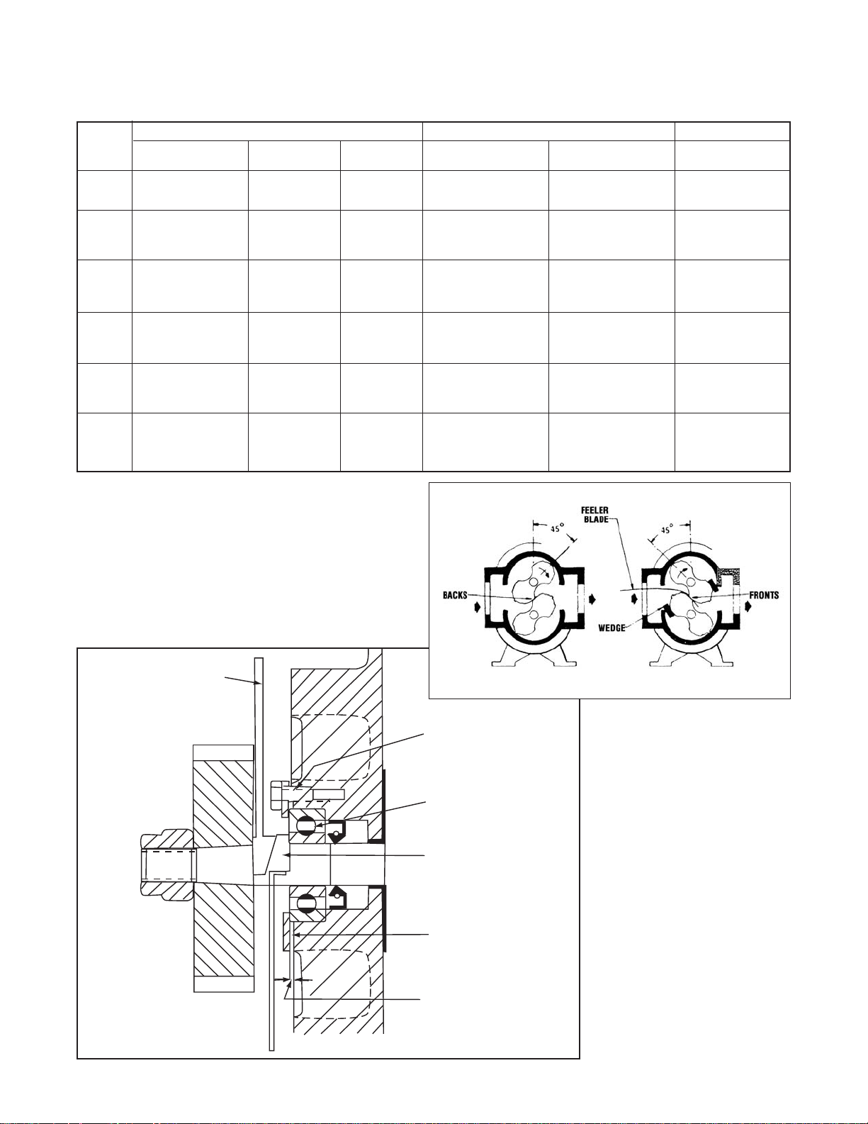
24For your nearest ROOTS Office, dial our Customer Service Hot Line 1 877 363 ROOTS (7668).
NORMAL CLEARANCES FOR UNIVERSAL RAI
®
AND URAI
™
-J, URAI™-G BLOWERS - INCHES (MM)
THRUST SETTING,
2-1/2”THRU 5”
UNIVERSAL RAI
®
BLOWERS
Impeller Ends Cylinder Impeller
Frame Total Drive End Gear End Inlet & Center Fronts/Backs
Size Minimum Minimum Discharge Center
22 .006/.010 (.15-.25) .003 (.08) .003 (.08) .004/.005 (.10-.13) .002/.003 (.05-.08) .007/.01 (.18-.25)
24 .006/.010 (.15-.25) .003 (.08) .003 (.08) .004/.006 (.10-.15) .002/.003 (.05-.08) .007/.01 (.18-.25)
32 .006/.011 (.15-.28) .003 (.08) .003 (.08) .004/.006 (.10-.15) .002/.003 (.05-.08) .01/.012 (.25-.30)
33 .006/.011 (.15-.28) .003 (.08) .003 (.08) .004/.006 (.10-.15) .002/.003 (.05-.08) .01/.012 (.25-.30)
36 .006/.011 (.15-.28) .003 (.08) .003 (.08) .004/.006 (.10-.15) .002/.003 (.05-.08) .01/.012 (.25-.30)
42 .008/.011 (.20-.28) .004 (.10) .004 (.10) .005/.007 (.13-.18) .003/.004 (.08-.10) .009/.012 (.23-.30)
45 .008/.013 (.20-.33) .004 (.10) .004 (.10) .005/.007 (.13-.18) .003/.004 (.08-.10) .012/.015 (.30-.38)
47 .008/.013 (.20-.33) .004 (.10) .004 (.10) .005/.007 (.13-.18) .003/.004 (.08-.10) .012/.015 (.30-.38)
53 .008/.011 (.20-.28) .004 (.10) .004 (.10) .005/.008 (.13-.20) .003/.004 (.08-.10) .011/.013 (.28-.33)
56 .008/.013 (.20-.33) .004 (.10) .004 (.10) .005/.008 (.13-.20) .003/.004 (.08-.10) .015/.017 (.38-.43)
59 .008/.013 (.20-.33) .004 (.10) .004 (.10) .005/.008 (.13-.20) .003/.004 (.08-.10) .015/.017 (.38-.43)
65 .012/.016 (.30-.40) .008 (.20) .004 (.10) .006/.008 (.15-.20) .006/.008 (.15-.20) .010/.014 (.25-.36)
68 .014/.018 (.36-.46) .010 (.25) .004 (.10) .006/.008 (.15-.20) .006/.008 (.15-.20) .010/.014 (.25-.36)
615 .014/.018 (.36-.46) .010 (.25) .004 (.10) .006/.008 (.15-.20) .006/.008 (.15-.20) .010/.014 (.25-.36)
76 .012/.016 (.30-.40) .008 (.13) .004 (.10) .006/.008 (.15-.20) .006/.008 (.15-.20) .013/.015 (.33-.38)
711 .014/.018 (.36-.46) .010 (.25) .004 (.10) .006/.008 (.15-.20) .006/.008 (.15-.20) .013/.015 (.33-.38)
718 .014/.018 (.36-.46) .010 (.25) .004 (.10) .006/.008 (.15-.20) .006/.008 (.15-.20) .013/.015 (.33-.38)
K-249392
IMPELLER TIMING FOR STANDARD
ROTATION VIEWED FROM GEAR END
TABLE 5
*
*
Thrust Adjuster
(ROOTS P/N 812-973-00X)
Fork
Nylok Capscrew
Bearing
Thrust Adjuster
Saddle
(ROOTS P/N 812-974-00X)
Clamp Plate
Gap (.03"-.05)
Page 26

25
©2002 Dresser, Inc.all rights reser ved.
ROOTS, RAM, URAI and WHISPAIR are trademarks of Dresser, Inc.
Dresser Design and Universal RAI are registered trademarks of Dresser, Inc.
Blower
Frame
Size
Fronts Backs
Each End
Without
Wavy Spring
Gear End
Without Spring
Installed
Required
End Float
Inlet
Center Discharge
Impeller Tips to CylindersEnd Clearance
Impeller Lobes
at 45°
Min-Max Min-Max Min-Max Min-Max Minimum Min-Max Min-Max Min-Max
404 .012-.014 .006-.009 .003-.005 .003-.008 .003 .004-.006 .002-.004 .002-.004
(.31-.36) (.15-.23) (.08-.13) (.10-.15) (.08-.20) (.08) (.05-.10) (.05-.10)
406 .012-.014 .006-.009 .003-.005 .007-.012 .006 .005-.007 .003-.005 .002-.004
(.31-.36) (.15-.23) (.08-.13) (.15-.30) (.13) (.13-.18) (.08-.13) (.05-.10)
409 .013-.015 .006-.009 .003-.005 .013-.018 .008 .005-.007 .003-.005 .002-.004
(.33-.38) (.15-.23) (.08-.13) (.31-.43) (.17) (.13-.18) (.08-.13) (.05-.10)
412 .013-.015 .006-.009 .003-.005 .016-.021 .011 .006-.008 .004-.006 .004-.006
(.33-.38) (.15-.23) (.08-.13) (.36-.48) (.28) (.15-.20) (.10-.15) (.10-.15)
418 .013-.015 .006-.009 .003-.005 .022-.027 .017 .008-.010 .004-.006 .004-.006
(.33-.38) (.15-.23) (.08-.13) (.51-.64) (.38) (.20-.25) (.10-.15) (.10-.15)
616 .012-.014 .006-.008 .004-.006 .017-.022 .011 .009-.011 .004-.006 .002-.005
(.31-.36) (.15-.20) (.10-.15) (.38-.51) (.28) (.23-.28) (.10-.15) (.05-.13)
624 .012-.015 .006-.009 .004-.006 .024-.029 .018 .013-.015 .005-.007 .002-.005
(.31-.36) (.15-.23) (.10-.15) (.61-.74) (.46) (.33-.38) (.13-.18) (.05-.13)
NORMAL CLEARANCES FOR RAM™-J & RAM™-GJ WHISPAIR
™
BLOWERS - INCHES (MM)
NORMAL CLEARANCES FOR RAM
™
BLOWERS - INCHES (MM)
Blower
Frame
Size
Fronts Backs
Each End
Without
Wavy Spring
Gear End
Without Spring
Installed
Required
End Float
Inlet
Center Discharge
Impeller Tips to CylindersEnd Clearance
Impeller Lobes
at 45°
404 .009-.013 .009-.013 .003-.005 .003-.008 .003 .004-.006 .002-.004 .004-.006
(.23-.33) (.23-.33) (.08-.13) (.08-.20) (.08) (.10-.15) (.05-.10) (.10-.15)
406 .009-.013 .000-.013 .003-.005 .007-.012 .006 .005-.007 .003-.005 .005-.007
(.23-.33) (.23-.33) (.08-.13) (.15-.30) (.13) (.13-.18) (.08-.13) (.13-.18)
409 .010-.014 .010-.014 .003-.005 .013-.018 .008 .005-.007 .003-.005 .005-.007
(.25-.36) (.25-.36) (.08-.13) (.31-.43) (.17) (.13-.18) (.08-.13) (.13-.18)
412 .010-.014 .010-.014 .003-.005 .016-.021 .011 .006-.008 .004-.006 .006-.008
(.25-.36) (.25-.36) (.08-.13) (.36-.48) (.28) (.15-.20) (.10-.15) (.15-.20)
418 .010-.014 .010-.014 .003-.005 .022-.027 .017 .008-.010 .004-.006 .008-.010
(.25-.36) (.25-.36) (.08-.13) (.51-.64) (.38) (.20-.25) (.10-.15) (.20-.25)
616 .011-.013 .011-.013 .004-.006 .017-.022 .011 .009-.011 .004-.006 .009-.011
(.28-.33) (.28-.33) (.10-.15) (.38-.51) (.28) (.23-.28) (.10-.15) (.23-.28)
624 .011-.013 .011-.013 .004-.006 .024-.029 .018 .013-.015 .005-.007 .013-.015
(.28-.33) (.28-.33) (.10-.15) (.61-.74) (.46) (.33-.38) (.13-.18) (.33-.38)
Min-Max Min-Max Min-Max Min-Max Minimum Min-Max Min-Max Min-Max
* IMPELLER TIMING FOR STANDARD ROTATION VIEWED FROM GEAR END
TABLE 6
*
*
Page 27
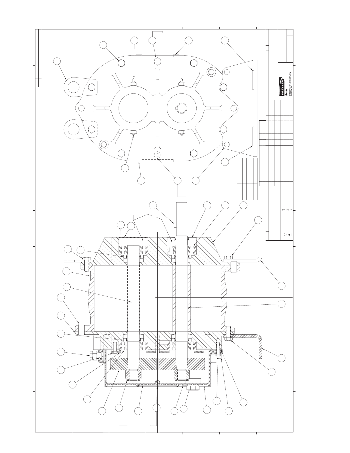
26For your nearest ROOTS Office, dial our Customer Service Hot Line 1 877 363 ROOTS (7668).
A
F:\ FILE\ FORM\ DSIZE.GCM
ASSEMBLY OF UNIVERSAL RAI
®
SERIES, AIR BLOWERS, 2-1/2” THRU 5” GEAR DIAMETER
.
'L
T
A
M
PART No.
PATT. No.
1110
46
PART NAME
No.
REQ'D.
987
6
A- INSTALL ITEM #20 (SCREW)IN ASSEMBLY
B- SEE OPERATING MANUAL IRB-180 FOR
LUBRICATION INSTRUCTION
C- 2-1/2, 3-1/2, & 4" REQ'D SOC. HD. ON G.E. ONLY
E- REQ'D ON 22 & 42 ONLY
F- NUT TO BE TORQUED TO:
2-1/2---60 LB.FT.
3-1/2---110 LB.FT.
B
26
4-------190 LB.FT.
5-------250 LB.FT.
G- FOR SIGHT GLASS UNITS ONLY.
USE WASHER OUTSIDE OF GEARBOX.
USE RED LOCTITE ON THE THREADS.
C
37
D
42
SEE NOTE
"E"
E
18
F
39
G
H
No.
ORDER
J
REV
FINISHED DIMENSIONS
DIMENSIONAL TOLERANCES UNLESS OTHERWISE SPECIFIED
TWO PLACE DECIMALS (.XX)---±.015 FRACTIONAL--±1/64
THREE PLACE DECIMALS (.XXX)--±.005
64720023
1110
TAPER BORE GEARS
SECTIONAL ASSEMBLY
2-1/2 THRU 5" U-RAI BLOWERS
DO NOT SCALE FOR DIMENSIONS
ALL DIMENSIONS SHOWN IN BRACKETS { } ARE MILLIMETERS
DATE
6-18-85
6-25-85
6-27-85
Y
R
O
FULL
T
C
E
IR
D
AP
FR
/
RM
E
IL
F
D
A
APP.
DR.
DBV
SCALE
CHKD.
C
/PARTS/XXAS
AP
AP
AP
98
AGP
AGP
7
2
#
R
D
T122
B
T-51
1
/0
0
/3
4
04/15/02
01/15/02
0
RK
RK
VC
S
IT
N
S U
0.731
0.585
0.427
2-1/2
S
LA
G
T
H
SIG
R
FO
45
#
EM
ADD LIFTING LUG ITEM# 46
DELETED ITEM 41
IT
D
D
A
G
J
H
38
18
SEE NOTE
"B"
39
0.831
40
19
SEE NOTE
"C"
35
33
"X" ±.005
543-1/2
SIZE
15
2
32
5
14
11.2378
SEE TABLE
MFG. REF.
c
FCR
V
-V
7
7
5
804
3
3
2-12-93
5-3-90
JHB
JHB
E
U
Q
R
TO
T
U
N
R
A
E
D G
E
S
EA
REVISED PER ECN
R
C
IN
E
F
CONFIDENTIAL
THIS DOCUMENT CONTAINS CONFIDENTIAL INFORMATION OF
CHKD. APP
FCR
FCR
M C
FCR
NOTICE
CHANGE
3339-V
3-19
87
8-7-86
8-26-86
10-16-86
9-03
87
BY DATE
REM
REM
RM
RM
DBREDRAWN
REVISIONS
REV PER ECN
ITEM #42 MOVED
LUBRICATION NOTE B REVISED
ITEM 25 REVISED PER ECN
D
C
B
A
7
CONCENTRICITY
PERPENDICULARITY
PROFILE OF LINE
PROFILE OF A SURFACE
DIAMETER
FINISH IN MICRO INCHES
ÿ
6
FLATNESS
ANGULARITY
PARALLELISM
TRUE POSITION
STRAIGHTNESS
REF: EP938
ROOTS DIVISION, DRESSER INDUSTRIES, INC. IT SHALL
BE HELD IN STRICTEST CONFIDENCE, AND BE USED ONLY
IN CONJUNCTION WITH ROOTS DIVISION BUSINESS.
32
27
NOTES:
54
54
11
13
321
25
31 27 1 16
351235
32
32
34
14
17
4
8
20
45
9
23
3
7
21
SEE NOTE "A"
(DO NOT DRILL
SEE NOTE
"F"
A
B
C
THRU)
SEE NOTE "G"
D
E
F
G
Page 28
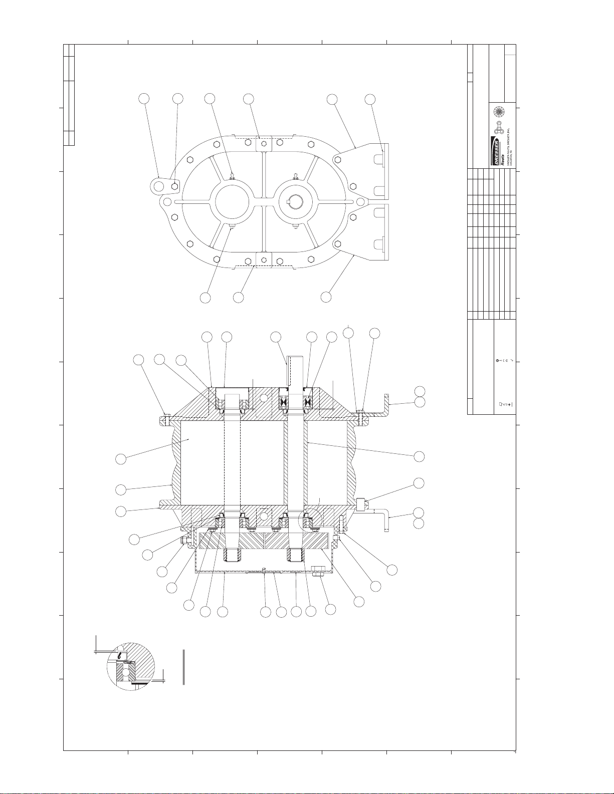
27
©2002 Dresser, Inc.all rights reser ved.
ROOTS, RAM, URAI and WHISPAIR are trademarks of Dresser, Inc.
Dresser Design and Universal RAI are registered trademarks of Dresser, Inc.
A
DSIZE.GCMFORM\FILE\F:\
ASSEMBLY OF UNIVERSAL RAI
®
BLOWERS, 6” AND 7” DIAMETER
.
'L
T
A
M
PART No.
PATT. No.
PART NAME
No.
10 11
REQ'D.
789
B
42
32
C
37
18
D
E
35
39
F
G
55-1242-2
No.
ORDER
DIMENSIONAL TOLERANCES UNLESS OTHERWISE SPECIFIED
WITH TAPER GEAR FIT
FOR 6" & 7" U-RAI BLOWER
SECTIONAL ASSEMBLY
DO NOT SCALE FOR DIMENSIONS
ALL DIMENSIONS SHOWN IN BRACKETS { } ARE MILLIMETERS
8-8
DATE
3-12
1986
12-8
1985
FCR
REM
APP.
DR.
CHKD.
FINISHED DIMENSIONS
1986
AP
DBV
AGP
F
REV
TWO PLACE DECIMALS (.XX)---±.015
THREE PLACE DECIMALS (.XXX)--±.005
FRACTIONAL--±1/64
64792023
10 11
Y
NTS
R
O
T
C
E
IR
D
E /
FIL
D
A
/PARTS/XXAS
SCALE
C
APPCHKD.
FCR AGP
NOTICE
CHANGE
3339-V
3389-V
3577-V
9-3
5-3
1986
1990
1987
DATEBY
11-21
2-25
1987
3-19
1987
4-21
1992
1-14
1988
REM
REM
REM
REM
REM
89
REVISIONS
38
2
18
5
19
36
6" ONLY
30
15
33
32
ADDED ITEM #43
ITEM 25 REVISED
ORIGINAL LOST/REDRAWN ON CAD DAC
INCREASED GEAR NUT TORQUE
B
C
D REMOVED ITEM #43
E
ADDED 7"
REDRAWN DB
A
7
27
26
6
11 13
1
45
27
29
25
0.1250
CONCENTRICITY
PERPENDICULARITY
PROFILE OF LINE
PROFILE OF A SURFACE
DIAMETER
FINISH IN MICRO INCHES
14
0.0625
0.0625
35
36
CONFIDENTIAL
REF. 862-600-023
MFG. REF.
ÿ
6
FLATNESS
ANGULARITY
PARALLELISM
TRUE POSITION
STRAIGHTNESS
REF: EP938
THIS DOCUMENT CONTAINS CONFIDENTIAL INFORMATION OF
ROOTS DIVISION, DRESSER INDUSTRIES, INC. IT SHALL
BE HELD IN STRICTEST CONFIDENCE, AND BE USED ONLY
IN CONJUNCTION WITH ROOTS DIVISION BUSINESS.
12
16
"X"
36
35
45
23
34
31
3
14
20
SEE NOTE "A"
9
8
17
SEE NOTE "D"
45
SEE NOTE "E"
21
4
23
123
A
0.1250
SEE NOTE "C"
B
VIEW "X"
(DO NOT DRILL THRU)
NOTES
A #25(.150) DRILL 1/4 DP & INSTALL
ITEM 20 (SCREWS) IN ASSEMBLY
B SEE OPERATING MANUAL IRB-180
FOR LUBRICATION INSTRUCTION
C INSTALL BEARINGS AS SHOWN BEFORE
SETTING END CLEARANCE
D NUT TO BE TORQUED TO:
6"---400 LB. FT.
7"---550 LB. FT.
E FOR SIGHT GLASS UNITS ONLY.
USE WASHER OUTSIDE OF GEARBOX.
USE RED LOCTITE ON THE THREADS.
C
D
E
F
G
0.0000
Page 29
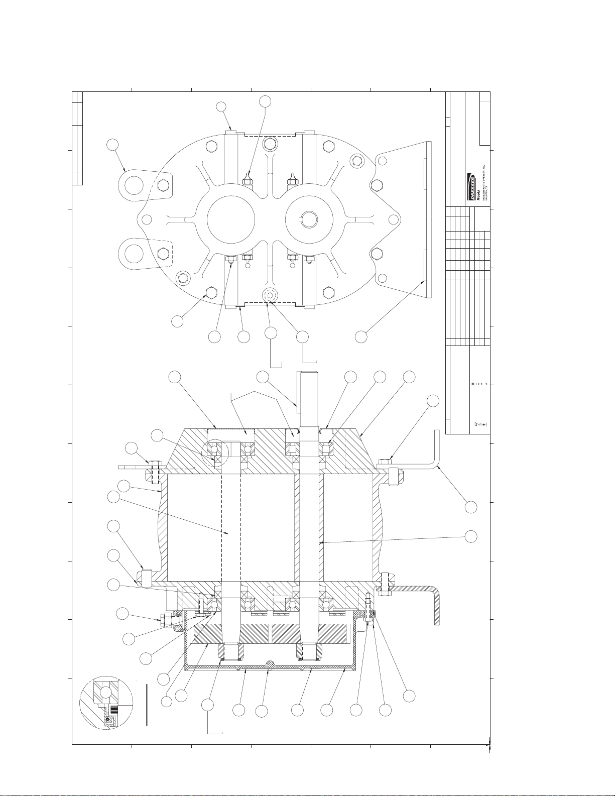
28For your nearest ROOTS Office, dial our Customer Service Hot Line 1 877 363 ROOTS (7668).
ASSEMBLY OF UNIVERSAL RAI
™
-G SERIES GAS BLOWERS, 3-1/2”THRU 5” GEAR DIAMETER
1110
987
.
'L
T
A
M
PART No.
PATT. No.
PART NAME
No.
REQ'D.
A
B
C
43
D
37
E
F
46
A
A
G
H
No.
ORDER
DO NOT SCALE FOR DIMENSIONS
ALL DIMENSIONS SHOWN IN BRACKETS { } ARE MILLIMETERS
DATE
REV
FINISHED DIMENSIONS
DIMENSIONAL TOLERANCES UNLESS OTHERWISE SPECIFIED
TWO PLACE DECIMALS (.XX)---±.015 FRACTIONAL--±1/64
THREE PLACE DECIMALS (.XXX)--±.005
SECTIONAL ASSEMBLY
3-1/2 THRU 5" U-RAI GAS BLOWERS
01/10/01
F
U
L
L
vc
APP.
DBV
DR.
SCALE
CHKD.
AGP
AGP
AGP
RK
RK
RK
RK
CHANGE
T102
PROTO
T122
T129
07/25/01
12/05/01
04/12/02
08/16/02
RKD
VC
RK
RKADD LIFTING LUG ITEM # 46
D
1110
T30099023
98
CHKD. APP
NOTICE
BY DATE
5
A- USE LOCKTITE #2 (30515) BETWEEN HEADPLATE AND
CYLINDER JOINTS.
B- SEE OPERATING MANUAL IRB-180 FOR GAS BLOWERS
FOR LUBRICATION INSTRUCTION.
C- 36,45 & 47 REQ'D SOC. HD. ON G.E. ONLY
E- REQ'D ON 32, 33 & 42 URAI-G ONLY-SEALING
WASHERS & BUTTONHEAD CAPSCREWS.
F- NUT TO BE TORQUED TO:
3-1/2---110 LB.FT.
4-------190 LB.FT.
6
NOTES:
5-------250 LB.FT.
27
32
54
11
13
321
27 1 16
25
26
REVISIONS
PICTURE CHANGEA
ADD 33 URAI-G TO NOTE E AND
44
18
38
19
SEE NOTE
"B"
SEE NOTE
" E"
40
SEE NOTE
"C" & "E"
39
2
15
33
32
DEL. FROM NOTE C
ADD ITEMS 8 & 20 (NAMEPLATE & SCREW)
C
B
CONCENTRICITY
PERPENDICULARITY
PROFILE OF LINE
PROFILE OF A SURFACE
DIAMETER
ÿ
CONFIDENTIAL
FLATNESS
ANGULARITY
PARALLELISM
TRUE POSITION
REF: EP938
MFG. REF.
THIS DOCUMENT CONTAINS CONFIDENTIAL INFORMATION OF
ROOTS DIVISION, DRESSER INDUSTRIES, INC. IT SHALL
BE HELD IN STRICTEST CONFIDENCE, AND BE USED ONLY
IN CONJUNCTION WITH ROOTS DIVISION BUSINESS.
7
FINISH IN MICRO INCHES
6
STRAIGHTNESS
54
3512
32
31
34
14
4
45
17
8
20
3
9
23
7
21
VIEW "X"
SEE NOTE
"F"
A
B
C
D
E
F
G
0.0000
0.0000 0.0000
F:\ FILE\ FORM\ DSIZE.GCM
Page 30
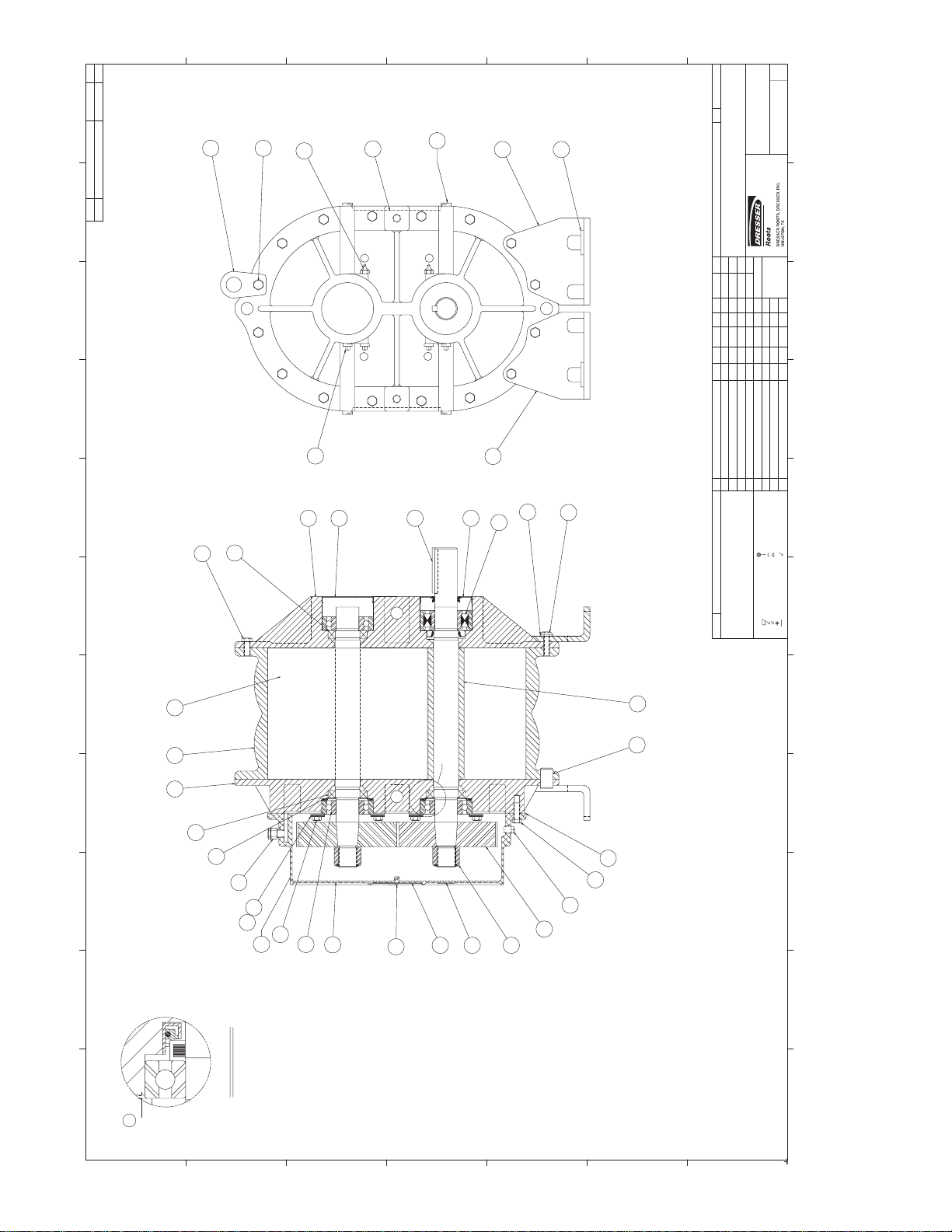
29
©2002 Dresser, Inc.all rights reser ved.
ROOTS, RAM, URAI and WHISPAIR are trademarks of Dresser, Inc.
Dresser Design and Universal RAI are registered trademarks of Dresser, Inc.
ASSEMBLY OF UNIVERSAL RAI
®
SERIES GAS BLOWERS, 6” GEAR DIAMETER
1110
F:\ FILE\ FORM\ DSIZE.GCM
987
6
.
'L
T
A
M
PART No.
PATT. No.
PART NAME
No.
REQ'D.
A
B
42
32
C
37
18
D
43
E
35
39
F
ORDER
No.
G
FINISHED DIMENSIONS
DIMENSIONAL TOLERANCES UNLESS OTHERWISE SPECIFIED
THREE PLACE DECIMALS (.XXX)--±.005
TWO PLACE DECIMALS (.XX)---±.015 FRACTIONAL--±1/64
B
REV
1110
T30110023
SECTIONAL ASSEMBLY
FOR 6" U-RAI GAS BLOWERS
DO NOT SCALE FOR DIMENSIONS
B
B
38
2
5
27
26
B
B
36
30
19
33
15
32
ALL DIMENSIONS SHOWN IN BRACKETS { } ARE MILLIMETERS
DATE
01/12/01
NTS
VC
APP.
DR.
DBV
SCALE
CHKD.
RK
RK
RK
CHANGE
T129
PROTO
PROTO
06/26/01
07/25/01
08/16/02
RK
VC
VC
ADDED DIMENSION .066
PICTURE CHANGE
ADD ITEMS # 8 & 20 (NAMEPLATE & SCREW)
A
B
C
CONCENTRICITY
PERPENDICULARITY
PROFILE OF LINE
PROFILE OF A SURFACE
DIAMETER
ÿ
CONFIDENTIAL
REF. 64792023
FLATNESS
ANGULARITY
PARALLELISM
TRUE POSITION
STRAIGHTNESS
REF: EP938
MFG. REF.
THIS DOCUMENT CONTAINS CONFIDENTIAL INFORMATION OF
ROOTS DIVISION, DRESSER INDUSTRIES, INC. IT SHALL
BE HELD IN STRICTEST CONFIDENCE, AND BE USED ONLY
IN CONJUNCTION WITH ROOTS DIVISION BUSINESS.
98
CHKD. APP
NOTICE
BY DATE
REVISIONS
7
FINISH IN MICRO INCHES
6
5
11 13
"X"
12
16
54
1
27
29
25
321
34
44
31
45
3
14
8
20
9
4
17
7
23
21
32
SEE NOTE "C"
NOTES
A USE LOCKTITE #2 (30515) BETWEEN
HEADPLATE AND CYLINDER JOINTS.
B SEE OPERATING MANUAL IRB-180 FOR
LUBRICATION INSTRUCTION
C NUT TO BE TORQUED TO:
6"---400 LB. FT.
VIEW "X"
A
0.1980
0.0000
A
B
C
D
E
F
G
0.0000 0.0000
Page 31
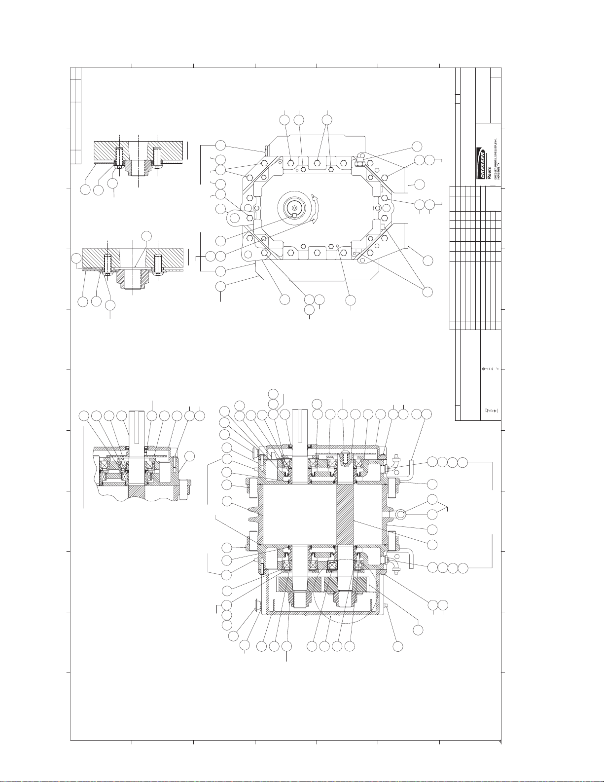
30For your nearest ROOTS Office, dial our Customer Service Hot Line 1 877 363 ROOTS (7668).
1110
ASSEMBLY OF RAM
™
SERIES AIR & GAS BLOWERS
987
.
'L
T
A
M
PART No.
PATT. No.
PART NAME
No.
REQ'D.
46
(600 RAM ONLY)
93
A
B
C
D
400 SEE NOTE
No. 6
23
400 SEE NOTE
No. 7
75
2
400400
400 RAM
87
91
SEE NOTE
NO. 8
23
23B
600
23A
63 66
DETAIL A
(600 RAM ONLY)
92
600 RAM
COMPRESSORS ONLY
FOR WATER SEALED
20 1944
42
600 SEE NOTE
No. 6 & 7
23
E
F
37
66
66A
76
23
23A
600
400
77
G
56-1010
FINISHED DIMENSIONS
No.
ORDER
DIMENSIONAL TOLERANCES UNLESS OTHERWISE SPECIFIED
TWO PLACE DECIMALS (.XX)---±.015 FRACTIONAL--±1/64
THREE PLACE DECIMALS (.XXX)--±.005
400/600 RAM
SECTIONAL ASSEMBLY
RAM/RAM-J/RAM-GJ/RAM-VJ
DO NOT SCALE FOR DIMENSIONS
ALL DIMENSIONS SHOWN IN BRACKETS { } ARE MILLIMETERS
DATE
11/26/96
11/26/96
11/27/96
11/26/96
AGP AGP
T43
04/04/01
NEP
DR.
RK
T22
10/05/00
BMS
CHKD.
AGP
RK
T16
11/17/00
RDA
APP.
NEPRLW6400V
9/14/99
RDR
6"=1'0"
NEP
DBV
SCALE
DBBMS5767V
NEPRLW5964V
3/24/98
7/7/98
RDR
NEP
SEE NOTE No. 6
RK AGP
T52
04/30/01
VC
RDABMS5560V
9/15/97
JPS
J
REV
81881023
CHKD. APP
NOTICE
CHANGE
5048V BMS RDA
12/5/96
BY DATE
NEP
1110
98
24
91
46
6
38
27
54
ALSO SHOWN AS GAS SERVICE
BOTTOM DRIVE OPTION
321
87
SEE NOTE No. 8
12
70
BOTTOM O.G.E. DRIVE ONLY
5
71
40
WHISPAIR UNITS ONLY
600
400
75
23
1
WHISPAIR UNITS ONLY
27
90
21
7
22
16 28
12
SEE NOTE No.2
128
WHISPAIR GAS PUMP
22
10
54
32
35
SEE NOTE No.3
63
66
23
66A
400
17
600
22
ADDED ITEMS 91,92,93, & DETAIL A
ADDED ITEM #90 VC
ADDED ITEM #88 VC
ADDED ELBOW & COUPLING VC
J
H
F
G
SEE NOTE No.1
SEE NOTE No.3
353234
50
33
70
38
49
SEE NOTE No.5
88
14
40
10
60
64
SEE NOTE No. 7
600
400
5
75
76
77
23
89
F
CONFIDENTIAL
MFG. REF.
THIS DOCUMENT CONTAINS CONFIDENTIAL INFORMATION OF
74
85
85A
REVISIONS
HORIZONTAL MOUNTING
REV. FOOT TO NEW STYLE DESIGNED FOR
ADDED BOLT TO G.E. SLINER
ADDED ITEM No. 23B
REVISED FOR 600 RAM
REVISED NOTE
A
B
C
E
D
7
CONCENTRICITY
PERPENDICULARITY
PROFILE OF LINE
PROFILE OF A SURFACE
DIAMETER
FINISH IN MICRO INCHES
ÿ
6
FLATNESS
ANGULARITY
PARALLELISM
TRUE POSITION
STRAIGHTNESS
REF: EP938
ROOTS DIVISION, DRESSER INDUSTRIES, INC. IT SHALL
BE HELD IN STRICTEST CONFIDENCE, AND BE USED ONLY
IN CONJUNCTION WITH ROOTS DIVISION BUSINESS.
54
1
22A
6
11
FOR GAS SERVICE
COMPRESSORS ONLY
13
COMPRESSORS ONLY
F
21
90
3
31
14
8
38
29
27
22
FOR WATER SEALED
89
74
85
85A
32
75
23
600
400
4
SEE NOTE No. 7
NOTES:
1. DRIVE END COVER TO BE PINNED TO HEADPLATE AFTER
ALIGNING SEAL BORE WITH SHAFT WITHIN .001
2. USE TEFLON SEALANT ON ALL PIPE THREADS & CYLINDER
TO HEADPLATE FLANGE FOR WHISPAIR GAS PUMP UNITS ONLY.
3. ITEMS 34 & 54 MUST BE INSTALLED WITH OIL GROOVE AT TOP.
4. TORQUE TO 400 FT.LBS.-400
TORQUE TO 630 FT.LBS.-600
5. TORQUE TO 75 FT.LBS.-400
TORQUE TO 140 FT.LBS.-600
APPLY LOCKTITE TO SCREW THREADS & BOTH FACES OF
WASHER & SLINGER.
A
6. TORQUE TO 35 FT.LBS. (HEADPLATE)
7. TORQUE TO 10 FT.LBS. (GEARBOX/END COVER)
8. LOCKTIGHT AND TORQUE TO FT.LBS.-85
B
SEE NOTE No.9
SEE NOTE No.4
F:\ FILE\ FORM\ DSIZE.GCM
0.0000
0.0000
C
D
E
F
G
0.0000
Page 32

31
©2002 Dresser, Inc.all rights reser ved.
ROOTS, RAM, URAI and WHISPAIR are trademarks of Dresser, Inc.
Dresser Design and Universal RAI are registered trademarks of Dresser, Inc.
UNIVERSAL RAI
®
SERIES BLOWERS PARTS LIST
1 Headplate Gear End 1
2 Headplate Drive End 1
3 Gearbo x 1
4 Gears 1
5Cover-Blind (Plug Opening) 1
7 Gasket 1
9 Nameplate Lube 1
14 Bearing G.E., - Driven 3
15 Bearing Drive D.E., - Drive 1
16 Pin, Dowel 4
17 Gear Nut 2
19 Key 1
20 Screw, Self Tap 1
21 Plug, Pipe 3
23 Screw Hex 6
25 Breather (Plug Vent) 1
26 Screw, Hex 14
27 Seal 4
29 Washer - wavy Spring 2
30 Washer 8
31 Screw, Hex 4
32 Screw, Hex 4
33 Seal Lip-Drive 1
34 Clamp Plate 2
35 Foot 2
36 Foot 2
37 Fitting, Grease 2
38 Fitting, Relief 2
39 Washer Flat 4
40 Screw Socket 2
40* Screw, Button Hd. 4
42 Screw Hex 2
43 Plug 8
44* Washer 4
Item No. Part Name Qty.
*For 32 and 42 URAI-G only.
Page 33

32For your nearest ROOTS Office, dial our Customer Service Hot Line 1 877 363 ROOTS (7668).
01 Headplate 2
03 Gearbox 1
04 Gear, Assembly 1
05 End Cover 1
07 Gasket – Gearbox/Cover 2
09 Installation Tag 2
10 Shims-(.010) Lot
14 Bearing Roller 4
16 Pin, Dowel (Pull Out) 4
17 Pin, Dowel 2
19 Key Square 1
20 Screw, Drive - Rd. Hd. 4
21 Breather 2
22 Plug, Pipe 12
23 Screw, Cap Hex Hd. 24
27 Seal, (Viton) 4
28 Piston, Ring-Seal 4
29 Washer , Wavy Spring 2
31 Nut, Hex ESNA 2
32 Scr, Cap Hex Hd. 16
33 Seal, Lip 1
34 Brg. Clamp Plate - D. E. 2
35 Lock Washer - Spring 16
37 Sight Plug - Oil Level 2
38 Sleeve - GE & DE 4
38 Sleeve - Piston Ring 4
40 Slinger - D.E.(Top Drive) 1
40 Slinger - D.E. (Bottom Dr ive) 1
42 Rotation Arrow 1
44 Label 1
46 Slinger - G.E. 1
49 Oil Leader L/S 1
50 Oil, Leader-R/S 1
54 Brg Clamp Plate - G. E. 2
60 Screw, Cap Butt. HD. 1
63 Lifting Lug 2
64 Pin, Spring 1
66 Screw, Cap Hex HD. 12
66.1 Whispair, Spring Lock 3/8M 12
70 Shims D.E.Brg. 1
75 Screw, Cap - Hex HD. 20
76 Blower Foot - RH 2
77 Blower Foot - LH 2
85 Elb, Pipe-Black 2
85.1 Plug, Pipe 2
87 Scr, Cap BH 2
88 Ball Spherical 4
90 BSHG-RDCG 2
91 Washer, Plain Flat 2
92 Washer, Plain Flat 2
93 Washer 2
RAM
™
SERIES PARTS LIST
Item No. Part Name Qty.
Page 34

NOTES
Page 35

Page 36

CONTACT LIST
CUSTOMER SERVICE
Dresser ROOTS
2135 Hwy 6 South
Houston, TX 77077
Toll Free Hot Line: 1-877-363-ROOT(S) (7668)
Toll Free Fax:1-877-357-7238
Local Fax:281-966-4309
ROOTS Factory Service & Repair Center
11611B Tanner RD
Houston, TX 77041
Toll Free: 1-800-866-6182
Local Phone: 713-896-4810
Local Fax:713-896-4927
Service & Warranty
Toll Free: 1-800-866-6182
Local Phone: 832-467-4614
Local Fax:713-896-4927
IRB-180-102
Rev. 12.02
©2002 Dresser, Inc.all rights reser ved.
ROOTS, RAM, URAI and WHISPAIR are trademarks of Dresser, Inc.
Dresser Design and Universal RAI are registered trademarks of Dresser, Inc.
Global Technology & Eng.
PO Box 687
Excelsior Springs, MO 64024
PH: 816-630-3500
FX: 816-630-3504
Toll Free: 1-866-630-3500
website: www.globaltecheng.com • email: [email protected]
Dresser, Inc.
 Loading...