

Page 1

Service manual
Rondostar 3000
SFS6115, SFS6115C, SFS6117,
SFS6117C, SFS6117H, SFS6117DD
SFI6117, SFI6117H
Edition SD123402
T echnical specifications subject to change without notice
HEADQUARTERS
RONDO Burgdorf AG
Heimiswilstrasse 42
3400 Burgdorf
Switzerland
Phone +41 (0)34 420 81 11
Fax +41 (0)34 420 81 99
info@rondo-online.com
COMPETENCE CENTRE SCHIO
RONDO Schio s.r.l.
Via Lago di Albano, 86
36015 Schio (VI)
Italy
Phone +39 0445 575 429
Fax +39 0445 575 317
schio@it.rondo-online.com
SUBSIDIARIES
RONDO GmbH & Co.KG
Hoorwaldstrasse 44
57299 Burbach
Germany
Phone +49 (0)2736 203-0
Fax +49 (0)2736 203130
info@de.rondo-online.com
RONDO S.à.r.l.
PAE "Les Pins"
67319 Wasselonne cedex
France
Phone +33 (0)3 88 59 11 88
Fax +33 (0)3 88 59 11 77
info@fr.rondo-online.com
RONDO Ltd.
Unit 7, Chessington Park
Lion Park Avenue
Chessington, Surrey KT9 1ST
Great Britain
Phone +44 (0)20 8391 1377
Fax +44 (0)20 8391 5878
info@uk.rondo-online.com
RONDO Inc.
51 Joseph Street
Moonachie, N.J. 07074
USA
Phone +1 201 229 97 00
Fax +1 201 229 00 18
info@us.rondo-online.com
RONDO Inc.
267 Canarctic Drive
Downsview, Ont. M3J 2N7
Canada
Phone +1 416 650 0220
Fax +1 416 650 9540
info@ca.rondo-online.com
RONDO S.r.l.
Via Lago di Albano, 86
36015 Schio (VI)
Italy
Phone +39 0445 576 635
Fax +39 0445 576 641
info@it.rondo-online.com
OOO RONDO
Varschavskoge Chaussée, D 17, Str. 3
117105 Moskau
Russia
Phone +7 (495) 786 39 06
Fax +7 (495) 788 98 20
info@rondo-online.ru
RONDO Asia
Regional Office
No. 14-1 Mezzanine Floor
Jalan 11/116B
Kuchai Entrepreneurs Park
Off Jalan Kuchai Lama
58200 Kuala Lumpur
Malaysia
Phone +60 3 7984 55 20
Fax +60 3 7984 55 95
info@my.rondo-online.com
www.rondo-online.com
Page 2

1. Safety regulations
2. Full view of the machine
3. Recommended spare parts
3.1 Mecanical spare parts
3.2 Electrical spare parts
4. Notes for the service
4.1 Important notes
4.1.1 Improvements on the Rondostar
4.1.2 Software changes
4.1.3 Usage of the new software
4.1.4 General view of the special functions
4.2 Initialisation
4.3 Calibrating the roller gap
4.4 Parameter
4.5 Diagnostic program
4.5.1 Selecting the diagnostic program
4.5.2 Checking the inputs
4.5.3 Allocation of the outputs
4.6 Operating hours counter
Index
5. Important notes, testing the drives
5.1 Mains voltage, mains frequency
5.1.1 Modifying the machine for a different mains voltage
5.1.2 Modifying the machine for another frequency
5.2 Functions of the machine
5.2.1 Machine start function
5.2.2 Roller adjustment drive function
5.2.3 Turning knob
5.3 Testing the drives
5.3.1 Direction of rotation of the drives
5.3.2 Testing the table- and roller drive
5.3.3 Testing the roller adjustment drive
5.3.4 Testing the flour duster
5.3.5 Testing the reeler
5.3.6 Testing the roller adjustment drive brake
5.3.7 Testing the Cutomat
5.4 Final control test
Page 3

6. Compound operation
6.1 General comments
6.2 Function
6.2.1 Compound operation with one make-up line respectively donut line
6.2.2 Positioning the dough
6.2.3 Release signal for transfer
6.3 Special parameters for compound operation
7. Instructions for trouble shooting
7.1 Error messages
7.2 Construction of the control system
7.3 Checking the control system
7.3.1 Mains voltage
7.3.2 Control voltages
7.3.3 Control circuit main contactor K1M
7.3.4 Measure of the voltage on the plugs
7.4 Important notes to the frequency inverter
7.4.1 Types
7.4.2 Parameterization
7.4.3 Ground fault interrupter can be actuated when inverter is started
8. Part names, drawings
8.1 Machine head front housing
8.1 Machine head front housing Cutomat / Compound
8.2 Machine head intermediate parts
8.3 Machine head rear housing
8.4 Machine bases
8.4.1 Machine base
8.4.2 Maschine base with support
8.4.3 Machine base SFI
8.5 Machine tables
8.5.1 Machine table Inox to Cutomat
8.5.2 Machine table Inox to support type
8.5.3 Machine table Inox to socle type
8.5.4 Flour catch pan
8.6 Cutting station / Machine table Cutomat
8.6.1 Adjustment of spring range
8.7 Flour duster
8.8 Automatic dough reeler
8.8.1 Convert the automatical dough reeler from the right to the left machine table
8.8.2 Reeler raise SFI61 17.E
8.9 Electrical box
8.10 Electrical box Cutomat
8.1 1 Front cover: Electrical equipment
9. Electro circuit diagrams
Page 4

Unbedingt zu beachtende Sicherheitsvorschrif ten und -hinweise
Bei allen Reparatur-, Inst andhaltungs-, Reinigungs- und ähnlichen Arbeiten an Maschinen
sind vor Beginn die Netzstecker herauszuziehen und alle eventuell vorhandenen
Druckluftzuleitungen zu unterbrechen und zu entlüften!
Weiter sind sämtliche Sicherheitsvorschriften und -hinweise, gemäss Betriebsanleitung
Kapitel 1, zu beachten!
Prescriptions et conseils de sécurité à observer obligatoirement
Avant tout travail de rép aration, d'entretien, de nettoyage et de travail analogue à la
machine retirer la fiche de contact et, le cas échéant, arrêter et purger tout
approvisionnement d'air comprimé!
De plus, il faut observer toutes les prescriptions et conseils de sécurité selon chapitre 1
du mode d'emploi!
Safety instructions and information which must be followed
Before beginning any repair , maintenance, cleaning or similar work on the machine
disconnect the mains plug and interrupt and deaerate all possible existing feeding pipes
of compressed air!
In addition, follow all safety instructions and information according to chapter 1 of the
operating manual!
Page 5
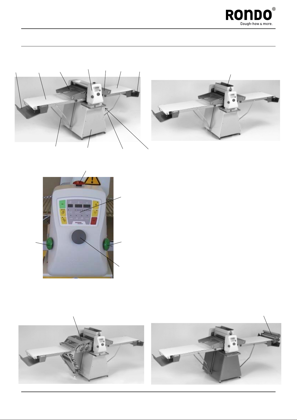
2 Full View of the Machine
1
SFS6115
5
8
4
11
3
6
10
4
5
11
12
1
7
1 Dough Catch Pan
2 Flour Duster (Option)
9
8
3 Roller Head
4 Safety Guard
5 Machine T able
6 Machine Base
7 Main Switch
8 Black Push Button for Starting
9 Control Panel
10 Red Push Button for Stopping
11 Forked Support
12 Turning knob for data input
13 Automatical Dough Reeler (Option)
14 Cutting Station (Option)
SFS6117
2
SFS6115C / SFS6117C
Edition: 04. 2005
14
SFS6117H
13
Service manual
Page 6
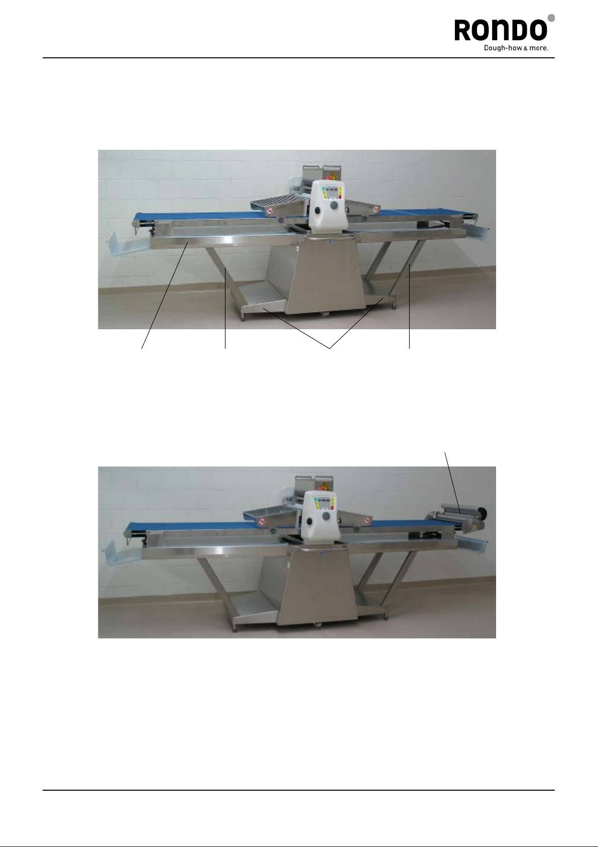
SFI6117
16
17
SFI6117H
15
17
13
13 Automatical Dough Reeler (Option)
15 Support
16 Lower Table
17 Forked Supports
Edition: 04. 2005
Service manual
Page 7

3. Empfohlene Ersatzteile / Pièces de rechange recommandes / Recommended spare parts
3.1 Mechanische Ersatzteile / Pièces de rechange mécaniques / Mecanical spare parts
Bestell-Nr.
No commande
Ordering no
50284 * Zahnriemen GT Courroie dentée GT Toothed belt GT
11532 Haltering Anneau de blocage Retaining ring
11935 Zahnriemen HTD Courroie dentée HTD Toothed belt HTD
11936 Zahnriemen HTD Courroie dentée HTD Toothed belt HTD
50048 Gasfeder 100N ohne
50283 Zahnriemen GT Courroie dentée GT Toothed belt GT
50453 Kupplung Dispositif d'accouplement Clutch
50474 Zahnriemen Courroie dentée Toothed belt
50485 Gasfeder 200N mit
50607 Rippenband Tapis gouffré Ribbed belt
91339T05 Antriebsrolle Rouleau d'entraînement Drive roller
105467 Kunststoffband 640 x 3280 Tapis synthétique
106570 Exzenterhebel Levier excentrique Eccentric lever
106593 Schaltsegment Segment Segment
108241 Schraubendruckfeder Ressort à pression Compression spring
121093 Teigrückhaltebügel Archet de retenue de pâte Dough retaining hoop
121344 Kunststoffband 640 x 3570 Tapis synthétique
121344T02 Kunststoffband 640 x 2680 Tapis synthétique
122775T03 Abstreifermesser Lame de racleur Scraper blade
123568 Zahnrad Z = 22 Roue dentée Z = 22 Gearwheel Z = 22
123570 Zahnrad Z = 15 Roue dentée Z = 15 Gearwheel Z = 15
124107 Zahnrad Z = 18 Roue dentée Z = 18 Gearwheel Z = 18
124108 Zahnrad Z = 16 Roue dentée Z = 16 Gearwheel Z = 16
124802 Zahnrad Z = 15 Roue dentée Z = 15 Gearwheel Z = 15
125908 Rippenbandscheibe Poulie courroie striée Ribbed V-belt pulley
125909 Rippenbandscheibe Poulie courroie striée Ribbed V-belt pulley
125910 Rippenbandscheibe Poulie courroie striée Ribbed V-belt pulley
125953 Feder Ressort Spring
125954 Abstreifer komplett Racleur complet Scraper complete
126055 Federstab Barre pour ressort Spring bar
126084 Rakel Racle Ductor
126088 Wischer Bras de monture d'essuie Wiper arm
133577T03 Abstreifermesser Lame de racleur Scraper blade
134823 Abstreifer komplett blau Racleur complet bleu Scraper complete blue
135341 Kunststoffband blau
* = Ausführung Cutomat/Version Cutomat/Type Cutomat
Automatischer Teighaspel / Enrouleur automatique de pâte / Automatic dough reeler
50466 O-Ring O-Anneau O-Ring
130530 Antriebsrad Z = 10 Roue dentée Z = 10 Gearwheel Z = 10
130531 Antriebsrad Z = 12 Roue dentée Z = 12 Gearwheel Z = 12
130532 Antriebsrad Z = 13 Roue dentée Z = 13 Gearwheel Z = 13
124595 Motor mit Kabel Linak Moteur avec câble Linak Motor with cable Linak
Teilebezeichnung
Désignation
Part name
automatischem Haspel
automatischem Haspel
640 x 3280
Vérin à gaz 100N sans
enrouleur automatique
Vérin à gaz 200N avec
enrouleur automatique
640 x 3280
640 x 3570
640 x 2680
Tapis synthétique bleu
640 x 3280
Pneumatic spring 100N
without automatic reeler
Pneumatic spring 200N with
automatic reeler
Synthetic conveyor belt
640 x 3280
Synthetic conveyor belt
640 x 3570
Synthetic conveyor belt
640 x 2680
Synthetic conveyor belt blue
640 x 3280
Page 8

3.2. Elektrische Ersatzteile / Pièces de rechange électriques /
Electrical spare parts
Bestell.Nr.
No commande
Ordering no.
8935 Feinsicherung 2,0A träg Fusible 2,0A lent Fuse 2,0A slow
9371 Endschalter Interrupteur fin de course Limit switch
11334 Empfängerkopf Tête de récepteur Receiver head
11335 Senderkopf Tête de transmetteur Transmitter head
50477 Grundmodul Module de base Modul basic
50481 Handrad komplett Roue à main compl. Handwheel compl.
50482 Absolutwertgeber Codeur en valeur absolue Rotary encoder
50483 Drehknopf Bouton tournant Turning knob
50495 Feinsicherung 0,63A träg Fusible 0,63A lent Fuse 0,63A slow
50587 Prozessoreinheit Unité microprocesseur Microprocessor unit
106111 Lichtschrankenkabel Câble pour cell. photoélectr. Cable for light barrier
106112 Lichtschrankenkabel Câble pour cell. photoélectr. Cable for light barrier
135202 *** Frequenzumrichter 230 V Variateur de fréquenze 230 V Frequency inverter 230 V
135203 *** Frequenzumrichter 400 V Variateur de fréquenze 400 V Frequency inverter 400 V
Bestell.Nr.
No commande
Ordering no.
12061 Drehstrommotor 0,09 kW Moteur triphasé 0.09 kW Motor three-phase 0.09 kW
35493 Motor mit Bremse Moteur avec freinage Motor with brake
50044 El. magnetische Bremse El. freinage magnétique El. magnetic brake
50359 *** Hilfskontaktblock Module de contacts auxiliaires Contact component auxiliary
50361 Kleinleistungschütz Contacteur de petit calibre Contactor miniature
50362 Kleinleistungsschütz Contacteur de petit calibre Contactor miniature
50484 Flachbandkabel 20-pol. Câble plat, 20 pol. Ribbon cable, 20 pol.
50588 *** Elektrische Kupplung
50603 Motor 1,1 kW 50/60 Hz Moteur 1,1 kW 50/60 Hz Motor 1,1 kW 50/60 Hz
50604 *** Zeitrelais Relais temporisé Time relais
50925 Pilztaster schwarz Bouton poussoir noir Push button black
50926 Pilztaster rot Bouton poussoir rouge Push button red
50927 Hilfsschalterblock 2S Bloc de contacts auxiliaires Contact block auxiliary 2S
50928 Hilfsschalterblock 10 Bloc de contacts auxiliaires Contact block auxiliary 10
51309 Motor 1,1 kW 60 Hz, UL Moteur 1,1 kW 60 Hz, UL Motor 1,1 kW 60 Hz, UL
*** Nur für Cutomat
1. Stufe Teilebezeichnung
Echelon 1 Désignation
Variation 1 Part name
2. Stufe Teilebezeichnung
Echelon 2 Désignation
Variation 2 Part name
Embrayage électrique
Cutomat
Cutomat
Electrical clutch
Cutomat
Page 9

____________________________________________________________________________________________________________________________________________________________________________________________________________________
4. Notes for the service
4.1 Important notes
4.1.1 Improvements on the Rondostar
In August 1998 the following changes have been made on the Rondostar.
Table drive:
Rondostar SFS611 is new equipped with clutches instead of the reversing gear (Like
Compas 3000).
Rondostar SFS611C (Cutomat, compound operation) is still equipped with the
reversing gear.
Light barrier wiper (screen wiper):
New light barrier wipers, mounted directly on the roller, as by Compas 3000.
Scraper:
New scraper system, consisting of 4 single scrapers instead of the pairs of scrapers.
4.1.2 Software changes
The following software changes have been made:
- Control system for the table clutches
- Changes in the control system of the screen wiper
- Modifications for compound operation with make-up lines and transfer table.
Previous software: 125921T01B V1.02
New software: 125921T01D V1.10
The EPROM is new marked as follows:
125921T01D / V1.10
125921T01D: Software identification by Seewer Rondo
V1.10: Software version, which is indicated below parameter 99 on the
display
The software version is new also indicated on the processor beside the mark of the
serial number.
4.1.3 Usage of the new software
The new software V1.10 can be used for all previous Rondostar.
In doing so pay attention to:
- Table drive: Table clutches Parameter 31 = 1
Reversing gear Parameter 31 = 0
- Light barrier cleaning: new system on the roller Parameter 32 = 2
Parameter 33 = 450
old system with catch Parameter 32 = 320
Parameter 33 = 120
By delivery of the processors the parameters for clutches and for the new light
barrier wipers are set.
______________________________________________________________________________________________________________________________________________________________________________________________________
Edition: 06.2011 Service manual
Page 10

____________________________________________________________________________________________________________________________________________________________________________________________________________________
4.1.4 General view of the special functions
The software for the RONDOSTAR is equipped with special functions to assist the technical
service.
Functions 1, 2: Access by the customer is possible (see operating manual)
For entering press the key "OK".
Other functions: For entering press the key "flour duster". The information on these
functions is not contained in the operating manual.
The individual functions must be selected using a function code.
Allocation of the function codes:
with key function
code FU
Description of the function See
chapter
"OK" 1 Parameters, access for customer possible ##
"OK" 2 Diagnosis for customer, inputs indicated,
##
access to outputs is not possible
Flour duster 10 Parameters, for technical service 4.4
Flour duster 20 Final control test 5.4
Flour duster 30 Diagnosis for technical service 4.5
Flour duster 40 Test roller adjustment 5.3.3
Flour duster 51 Initialisation of the parameters 4.2
Flour duster 53 Initialisation of the programs 4.2
Flour duster 55 Full initialisation (parameters and programs) 4.2
Flour duster 67 Calibration of roller gap 4.3
Flour duster 70 Display operating hours counter 4.6
Flour duster 99 Indication of the software version -----
## For description of the functions see the operating manual
The functions listed above are described in detail in the following chapters.
Warning
Changing the functions requires great care and forethought.
4.2 Initialisation
Function
When the processor is initialised, the basic data (parameters, sheeting programs) are loaded
from the program EPROM into the processor's working memory.
When initialisating, all previously entered data such as customer programs, special parameters,
etc. are overwritten by the basic data.
______________________________________________________________________________________________________________________________________________________________________________________________________
Edition: 06.2011 Service manual
Page 11

____________________________________________________________________________________________________________________________________________________________________________________________________________________
When should the initialisation be carried out?
- Following the installation of a new processor in the machine
Full initialisation (FU 55)
- Where faults are suspected in the processor's control procedure (software errors)
In this case proceed as follows:
Initialise the parameters (FU 51) ---> then test the machine
- If the problems are not rectified
Full initialisation (FU 55) ---> then test the machine
This results in the loss of all sheeting programs
memorised by the customer!
- If only the customer programs are to be deleted
Initialise the programs (FU 53) ---> all sheeting programs are deleted
How to initialise?
Example: In order to initialise the parameters (FU 51) proceed as follows:
- Switch on working mode "Auto" LED "Auto" on continuously
- Press key "Flour Duster" for approx. 10 s Indication: FU 0 --
- Set "51" by turning knob Indication: FU 51 --
- Press key "OK" till Indication: FU 0 --
- Return to sheeting program Press the key "ESC"
4.3 Calibrating the roller gap
Calibration of the roller gap is imperative if:
- the processor has been changed
- changes are made to the absolute value sender (toothed belt, attachment of the sender,
etc.)
- the roller gap shown on the display does not coincide with the actual roller gap
The calibration of the roller gap takes place by a roller gap of 4,0 mm.
Proceed as follows:
- Switch off the machine at the main switch
- Set the roller gap to 4,0 mm, e.g. by turning the brake disk of the roller engagement
drive. Check the roller gap with e.g. a 4,0 mm large sheet.
- Switch on the machine at the main switch
- Press key "Flour duster" for approx. 10 s Indication: FU 0 --
- Set "67" by turning knob Indication: FU 67 XX,X-
- Press key "OK" till Indication: FU 67 4,0
Calibration is complete
Return to the sheeting program: Press the key "ESC"
XX,X = Numerical value
The calibration of the roller gap is not affected by initialisation and is not deleted.
______________________________________________________________________________________________________________________________________________________________________________________________________
Edition: 06.2011
Service manual
Page 12

____________________________________________________________________________________________________________________________________________________________________________________________________________________
4.4 Parameter
Key Funct. Param. Description Value Unity
OK 1 0 Entering data: Side end for folding not defined 0
Side end for folding right 1
Side end for folding left 2
OK 1 1 Entering data: Side end for man. reeling not defined 0
Side end for man. reeling right 1
Side end for man. reeling left 2
OK 1 2 Compound operation: Time band stop waiting postion 15 0,1 s
OK 1 3 Compound operation: Time for transfer 300 0,1 s
FD 10 10 Entering data: no Auto-reeler 0
Auto-reeler right 1
Auto-reeler left 2
FD 10 11 Entering data: no cutomat 0
Cutomat right 1
Coutomat left 2
FD 10 12 Time Auto-reeler finished
photocell free --> conveyor belt stop
FD 10 13 Time handreeler finished
photocell free --> conveyor belt stop
FD 10 14 Position of the dough handreeler placement
Dough in photocell --> conveyor belt stop
FD 10 15 Time conveyor belt stop for folding
photocell free --> conveyor belt stop
FD 10 16 Time conveyor belt stop for cutomat
photocell free --> conveyor belt stop
FD 10 17 Roller opening by cutting (Cutomat) 50 0,1 mm
FD 10 18 Time open Auto-reeler 12 0,1 s
D 10 19 Time close Auto-reeler 15 0,1 s
FD 10 20 max. dough thickness in mm for Auto-reeler 90 0,1 mm
FD 10 21 Delay time dough in photocell 2 0,1 s
FD 10 22 Indicator period 8 0,1 s
FD 10 23 Indicator break 2 0,1 s
FD 10 24 Cutomat: running time high speed at the start 10 0,1 s
FD 10 25 On delay-time for flour duster 8 0,1 s
FD 10 26 Time for changing the program-no. (Flashing of the program-no) 50 0,1 s
FD 10 27 Time press the key for selecting the program mode 30 0,1 s
FD 10 28 "long time" for key OK respectively flour duster for special
functions
FD 10 29 "short time" for key OK respectively flour duster for special
functions
FD 10 30 Compound operation:
no compound operation 0
compound left 1
compound right 2
compound operation left/right no passages without roller
adjustment (special) 3
compound operation left/right: for left machine place dough on
left side, for right machine place dough on right side 4
FD 10 31 Rondostar with table clutch 1
Rondostar with reversing gear 2
(Cutomat/Compound, machine delivery before August 1998)
FD 10 32 Light barrier wiper "above"
For new screen wiper on the roller, inactive 2
For old screen wiper with catch, function active 320
FD 10 33 Light barrier wiper "below"
For new screen wiper on the roller, inactive 450
For old screen wiper with catch, function active 120
Values in brackets are valid for short tables
______________________________________________________________________________________________________________________________________________________________________________________________________
Edition: 06.2011
Service manual
1
1
0
0
15
(10)
15
(10)
15
(10)
2 0,1 s
2 0,1 s
100 0,1 s
30 0,1 s
0
1
2
450
0,1 s
0,1 s
0,1 s
Page 13

____________________________________________________________________________________________________________________________________________________________________________________________________________________
Notes
Key: Select special functions with the key "OK" or with the key "flour duster"
The customer has the option, to change parameter 0, 1, 2 and 3.
See description in the operating manual.
Function: The function is selected with the turning knob.
Function 10 and the associated parameters are exclusively intended for the
Parameters: The parameters are selected with the turning knob and confirmed with "OK"
technical service (no notes in the operating manual).
Value: The figures given in the column "value" are loaded into the working memory from
the EPROM during initialisation and may subsequently be changed.
Attention: By the software version V1.02 it was as follows:
- Parameter 31: Time for transfer in the compound operation
- Parameter 32: Time band stop waiting position in the compound operation
There were no parameters for the light barrier wipers.
Changing the parameters:
Example: The time to switch to "programming" is to be changed from 3 s to 5 s.
Use function (FU) 10 to change parameter (PA) 27 from 30 to 50
- Switch on working mode "Auto" LED "AUTO" on continuously
- Press key "flour duster" during 10 s Indication: FU 0 --
- Set "10" by turning knob Indication: FU 10 --
- Press key "OK" till Indication: PA 10** (0)
- Set parameter "27" by turning knob Indication: PA 27** 30
- Press key "OK" till Indication: PA 27 30**
- Set value "50" by turning knob Indication: PA 27 50**
- Press key "OK" Indication: PA 28** XX,X
return to the sheeting program: Press key "ESC" twice
XX,X = Numerical value ** = Indication is flashing
4.5 Diagnostic program
The Rondostar is fitted with an automatic direction of rotation control, i.e. after switching on
the electricity supply (mains switch), when a sheeting program is started for the first time, the
direction of rotation of the mains is checked. The drives are subsequently controlled in
accordance with the direction of rotation of the mains.
Before using the diagnostic program, the machine is briefly started in a sheeting program or in
the working mode "manual" (direction of rotation check). As soon as the conveyor belts start to
move, the machine can be stopped and the program may be aborted using "ESC". The turning
direction of the net will be indicated with LED 9 (see chapter 4.5.2)
______________________________________________________________________________________________________________________________________________________________________________________________________
Edition: 06.2011 Service manual
Page 14

____________________________________________________________________________________________________________________________________________________________________________________________________________________
4.5.1 Selecting the diagnostic program
- Switch on working mode "Auto" LED "AUTO" on continuously
- Press key "flour duster" during 10 s Indication: FU 0 --
- Set function "30" by turning knob Indication: FU 30 --
- Press key "OK" till Indication: d. 1** 0
- Return to the sheeting program: Press key "ESC" twice
** = Indication is flashing
4.5.2 Checking the inputs
The statuses (On/Off) of the inputs are displayed on the LED of the roller reduction steps,
whereby they are numbered 1 - 9 from left to right.
LED No. 1 Control voltage processor Control voltage OK = 1
LED No. 2 General control voltage Control voltage OK = 1
LED No. 3 Right push button Right push button operated = 1
LED No. 4 Left push button Left push button operated = 1
LED No. 5 Main contactor K1M Main contactor engaged = 1
LED No. 6 Frequency inverter, Frequency inverter and
contactor K2M contactor K2M ON = 1
LED No. 7 Turning knob Slow turning of turning knob = 0/1
LED No. 8 Photocell Photocell covered = 1
Photocell free = 0
LED No. 9 Direction of rotation of mains Right rotating field = 0
Left rotating field = 1
"1" indicates that the corresponding LED illuminates
"0/1" indicates that the LED switches on and off when the turning knob is turned.
"0" indicates that the corresponding LED is switched off
If all inputs should be tested, proceed as follows:
Select the diagnostic program (FU30)
Safety guard open illuminate: LED1, LED2
These two LED have to illuminate always.
Close safety guard
Press right push button illuminate: LED3 LED5 LED6
Push button no longer pressed illuminate: LED5 LED6
Press left push button illuminate: LED4 LED5 LED6
Push button no longer pressed illuminate: LED5 LED6
Open safety guard LED5 has to switch off imediately
LED6 has to switch off with approx 1 s delay
Turn turning knob slowly LED7 has to illuminate
Photocell LED8 illuminates when photocell is covered
LED8 doesn't illuminate when photocell is free
______________________________________________________________________________________________________________________________________________________________________________________________________
Edition: 06.2011
Service manual
Page 15

____________________________________________________________________________________________________________________________________________________________________________________________________________________
4.5.3 Allocation of the outputs
After leaving the diagnostic program, all outputs are automatically returned to their former status.
Functions of the processor outputs
Output
processor
A0 Supervision processor
A2 Table drive:Conveyor-
A11 Table drive:Conveyor-
A5 Table clutches
A6 Roller adjustment
A10 Roller adjustment
A7 Roller adjustment
A9 Flour duster
A8 Direction of rotation flour
A4 Selection between
A3 Auto reeler, table
A1 Reeler
Function by
mains right rotating field
LED No. 9 dark
(watch-dog)
belt runs to the left
belt runs to the right
0 = left clutch
1 = right clutch
Cutomat:
1 = small number of
revolutions
1 = drive ON
0 = upward
1 = downward
1 = Brake ON
1 = Flour duster ON
duster 0 by right rotating
field
0 = reeler
1 = table clutch /
Cutomat clutch
clutches, Cutomat clutch
1 = ON
0 = Open reeler
1 = Close reeler
Function by
mains left rotating field
LED No. 9 illuminates
Supervision processor
(watch-dog)
Table drive:
Conveyor-belt runs to the
right
Table drive:
Conveyor-belt runs to the
left
Table clutches
0 = left clutch
1 = right clutch
Cutomat:
1 = small number of
revolutions
Roller adjustment
1 = drive ON
Roller adjustment
0 = downward
1 = upward
Roller adjustment
1 = Brake ON
Flour duster
1 = Flour duster ON
Direction of rotation flour
duster 1 by left rotating
field
Selection between
0 = reeler
1 = table clutch /
Cutomat clutch
Auto reeler, table
clutches, Cutomat clutch
1 = ON
Reeler
0 = Open reeler
1 = Close reeler
Relay
contactor
K8 Cannot be switched on
K9/K2M
F-inverter
K10/K3MF
-inverter
K13 Rondostar with table
K1/ K2
K5
K7
K3 / K4
K6
K14
K12 Switch on / off
K11
Remarks
or off
processor fault A1=0
By Cutomat:
Conveyor-belt runs
always to the left
By Cutomat:
Conveyor-belt runs
always to the right
clutches
Note:
The drives for roller adjustment and reeler each have:
- 1 relay for drive ON/OFF
- 1 relay for the direction of movement up/down respectively open/close
With outputs A2, A8, A10, A11 the function changes when the direction of rotation of the
mains changes.
Output A2: SFS Contactor K2M motor main drive, direction dough to left/right
depends of mains direction of rotation.
SFS Cutomat Signal to frequency inverter, direction dough to the left
Output A11: SFS Contactor K3M motor main drive, direction dough to the
left/right depends of mains direction of rotation
SFS Cutomat Signal to frequency inverter, direction dough to the right
______________________________________________________________________________________________________________________________________________________________________________________________________
Edition: 06.2011
Service manual
Page 16

____________________________________________________________________________________________________________________________________________________________________________________________________________________
Consider: - What do I want to switch on?
- Which output must be switched?
- Is the correct output selected?
The drives can only be started when the safety guards have been closed.
The individual outputs can be switched on and off as follows:
- Switch on working mode "Auto" LED "AUTO" on
continuously
- Press key "flour duster" during approx 10 s Indication: FU 0 --
- Set function "30" by turning knob Indication: FU 30 --
- Press key "OK" till Indication: d. 1** 0
- Select output (for example A7) by turning knob Indication: d. 7** 0
- Switch on output by key "OK" Indication: d. 7 1
- Switch off output by key "OK" Indication: d. 7 0
- Return to the sheeting program: Press key "ESC" twice
** = Indication is flashing
In order to test the drives a number of special test programs are available.
Testing of the individual drives is described in detail in chapter 5.3.
4.6 Operating hours counter
The processor is fitted with an operating hours counter. The counter reading can be called up
using function 70.
The display is given in hours.
In order to read the operating hours counter, proceed as follows:
- Switch on working mode "Auto" LED "AUTO" on continuously
- Press key "flour duster" during 10 s Indication: FU 0 --
- Set "70" by turning knob Indication: FU 70 --
- Press key "OK" (10 s) till Indication: h 000 045
(45 hours)
- Return to the sheeting program: Press key "ESC" twice
______________________________________________________________________________________________________________________________________________________________________________________________________
Edition: 06.2011 Service manual
Page 17

____________________________________________________________________________________________________________________________________________________________________________________________________________________
5. Important notes, testing the drives
Notes:
Rondostar without Cutomat:
The drive motor for tables and rollers is supplied directly from the mains.
Rondostar with Cutomat (variable speed):
The drive motor for tables and rollers is supplied by a frequency inverter during the sheeting and
also during the cutting process.
Attention:
For the operating voltages 200 - 230 V and 380 - 460 V different types of frequency inverters and
mains filters are necessary.
5.1 Mains voltage, mains frequency
The mains voltage and mains frequency must coincide with the data given on the machine
specification plate.
The specification plate is to be found on the substructure where the mains cable input is
located.
The prescribed maximum fusing must be observed.
5.1.1 Modifying the machine for a different mains voltage
Motors: Table drive motor, roller adjustment motor, flour duster motor
200 - 230 V Motors delta-connected
380 - 460 V Motors star-connected
Attention: Rondostar with Cutomat (variable speed) cannot be switched over
from 200 - 230 V to 380 - 460 V. (Different frequency inverters!)
Transformer:
The transformer in the basic module must be switched to the new voltage.
5.1.2 Modifying the machine for another frequency
The following parts depend of the value of the frequency:
50 Hz 60 Hz
motor 50400 50421
V-belt pulley 124128 124138
V-belt 50401 50403
Attention: Rondostar with Cutomat (variable speed) can be operated with 50 or 60 Hz
without a change.
______________________________________________________________________________________________________________________________________________________________________________________________________
Edition: 06.2011 Service manual
Page 18

____________________________________________________________________________________________________________________________________________________________________________________________________________________
5.2 Functions of the machine
5.2.1 Machine start function
When the machine is started, the following control process runs automatically:
1. One of the black push buttons is operated.
Here the black push buttons have a dual function.
On the one hand they switch on the main contactor, on the other hand they issue the
command for the direction of rotation of the conveyor belt to the processor.
2. Main contactor K1M engages.
3. At the time of the first start after switching on the mains, the direction of rotation of the
mains is checked automatically as follows:
The roller drive is briefly switched on and the direction of rotation of the motor is
checked. If the roller rises when given the command "close" (wrong direction), the
direction of rotation of the table, roller adjustment and flour duster drives is
automatically changed.
4. The roller adjustment drive starts and the roller moves to the roller gap shown in the
display. At the same time the automatic reeler is opened if it is not already in the upper
end position.
5. The table drive starts automatically when the roller end position is reached.
5.2.2 Roller adjustment drive function
The position of the roller gap is measured with an absolute value sender. With an angle of
rotation of 360° (roller gap 45.0 - 0.2 mm), the absolute value sender has 256 positions. A
specific roller gap is allocated to each of these 256 positions in the software.
Here the correct calibration of the absolute value sender at a roller gap of 4.0 mm is
paramount. (See chapter 4.3)
The direction of rotation of the mains is checked using the roller adjustment drive. The
controls of the table drive and the flour duster are dependent on the direction of rotation of
the roller adjustment drive.
5.2.3 Turning knob
The turning knob consists of an impulse sender with 128 impulses per revolution.
The turning knob is used to input the data during programming, when selecting the program
and during diagnostic work, etc.
______________________________________________________________________________________________________________________________________________________________________________________________________
Edition: 06.2011 Service manual
Page 19

____________________________________________________________________________________________________________________________________________________________________________________________________________________
5.3 Testing the drives
5.3.1 Direction of rotation of the drives
The machine automatically tests the direction of rotation of the mains and controls the
machine accordingly.
The roller adjustment drive always depends directly on the direction of rotation of the
mains.
If the direction of movement of the table drive or of the flour duster is incorrect, proceed as
follows:
Flour duster: Switch 2 phases on the motor terminals
Table drive: First check if the black push buttons are correctly connected.
(See checking the inputs, chapter 4.5.2, LED 3 and LED 4)
Are the push buttons correctly connected, switch 2 phases of the
motor cable on contactor K2M.
5.3.2 Testing the table- and roller drive
Testing the drive
Testing the drive is best not carried out in the diagnostics program but directly in the working
mode "Manual".
Proceed as follows:
- Select "Manual" working mode
- Operate left push button conveyor belt must run to the right
Stop by using red push button
- Leave the program with "ESC"
- Operate right push button conveyor belt must run to the left
Stop by using red push button
- Leave the program with "ESC"
Testing the clutches table drive
Note: The clutch of the infeed belt is always switched on.
The infeed belt only runs when the clutch is switched on!
For testing the clutches in the diagnostic program, proceed as follows:
Switch on diagnostic program as described under 4.5.1
Testing the left clutch:
- Set d = 4 by turning knob Indication: d 4** 0
- Switch on by key "OK" Indication: d 4** 1
- Set d = 3 by turning knob Indication: d 3** 0
- Switch on clutch by key "OK" Indication: d 3** 1
** = Indication is flashing
______________________________________________________________________________________________________________________________________________________________________________________________________
Edition: 06.2011 Service manual
Page 20

____________________________________________________________________________________________________________________________________________________________________________________________________________________
Testing the right clutch:
- Set d = 4 by turning knob Indication: d 4** 0
- Switch on by key "OK" Indication: d 4** 1
- Set d = 5 by turning knob Indication: d 5** 0
- Switch on by key "OK" Indication: d 5** 1
- Set d = 3 by turning knob Indication: d 3** 0
- Switch on clutch by key "OK" Indication: d 3** 1
** = Indication is flashing
5.3.3 Testing the roller adjustment drive
In order to test the roller adjustment drive, a special test program "Test roller
adjustment" is available. Proceed as follows:
- Switch on working mode "Auto" LED "AUTO" on continuously
- Press key "flour duster" during 10 s Indication: FU 0 --
- Set "40" by turning knob Indication: FU 40 --
- Press key "OK" till Indication: d. XX,X 45,0**
- Set roller gap (example 35 mm) by turning knob Indication: d. XX,X 35,0**
- Close safety guard
Start of the roller adjustment drive by black push button
Roller moves to the selected roller gap Indication: d. 35,0 35,0**
XX,X = Numerical value
** = Indication is flashing
5.3.4 Testing the flour duster
The correct direction of rotation for the flour duster has been determined by the automatic
check on the direction of rotation of the mains. (Do not change output A8).
To check the flour duster, switch on the diagnostic program as described under 4.5.1
- Switch on working mode "Auto" LED "AUTO" on
continuously
- Press key "flour duster" during approx. 10 s Indication: FU 0 --
- Set function "30" by turning knob Indication: FU 30 --
- Press key "OK" till Indication: d. 1** 0
Now the diagnostic program is switched on
** = Indication is flashing
Processor output 9, flour duster On / Off
- Close safety guard, press the black push button briefly
- Set d = 9 by turning knob Indication: d 9** 0
- Flour duster ON by key "OK" Indication: d 9** 1
- Flour duster OFF by key "OK" Indication: d 9** 0
** = Indication is flashing
______________________________________________________________________________________________________________________________________________________________________________________________________
Edition: 06.2011 Service manual
Page 21

____________________________________________________________________________________________________________________________________________________________________________________________________________________
5.3.5 Testing the reeler
The motor of the reeler drive is equipped with limit switches which automatically interrupt the
electricity supply in the end position.
To check the reeler in the diagnostic program proceed as follows:
Switch on diagnostic program as described under 4.5.1
Switch on reeler
- Set d = 3 by turning knob Indication: d 3** 0
- Reeler ON by key "OK" Indication: d 3** 1
The reeler is now switched on
Open / close reeler
- Set d = 1 by turning knob Indication: d 1** 0 (1)
The reeler can now be opened and closed by the key "OK".
- Press key "OK": Close reeler, wait until the reeler
is closed completely Indication: d 1** 1
- Press key "OK": Open reeler, wait until the reeler
is opened completely Indication: d 1** 0
** = Indication is flashing
Warning: Do not change the direction of rotation while the reeler is moving.
5.3.6 Testing the roller adjustment drive brake
In order to test the brake of the roller adjustment drive in the diagnostic program, proceed
as follows:
- Switch on the diagnosic program as described under 4.5.1
- Set d = 7 by turning knob Indication: d 7** 0
- Brake ON by key "OK" Indication: d 7** 1
- Brake OFF by key "OK" Indication: d 7** 0
** = Indication is flashing
______________________________________________________________________________________________________________________________________________________________________________________________________
Edition: 06.2011 Service manual
Page 22

____________________________________________________________________________________________________________________________________________________________________________________________________________________
5.3.7 Testing the Cutomat
For the operation Cutomat the Cutomat clutch (outputs A3 and A4 = 1) as well as the slow
speed (output A5 = 1) have to be switched on.
For testing the function Cutomat, set a simple auto-program with Cutomat in program 1,
3 positions:
Initial roller gap 10 mm
Final roller gap 6 mm
Roller reduction curve 5
Function Cutomat:
Now the program will start in the final test (See 5.4). If the endthickness is reached, start
the machine with the black push button.
Now the rollers open about 5 mm and the machine starts with the Cutomat speed. The
table on the infeed side has to run exactly as fast as the table on the outfeed side. A click
of the driving wheels in the front housing is audible (normal).
5.4 Final control test
For the final control test an automatic sheeting program (without dough) is used in a
continuous way. The running time for the table drive in either direction of operation is
approx. 3 s.
Warning:
Continuous operation is only possible using programs with the functions "Stop for
folding" or "automatic reeling".
- Switch on working mode "Auto" LED "AUTO" on continuously
- Press key "flour duster" during approx. 10 s Indication: FU 0 --
- Set "20" by turning knob Indication: FU 20 --
- Press key "OK" till Indication: FU 0 --
- Press key "OK", program no. 1 is displayed Indication: 01** XX,X XX,X
- Select desired testing program by turning knob
Start machine with black push button, stop machine with red push button or safety
guard.
Return to normal sheeting mode: Press key "ESC"
XX,X = Numerical value ** = Indication is flashing
______________________________________________________________________________________________________________________________________________________________________________________________________
Edition: 06.2011 Service manual
Page 23

____________________________________________________________________________________________________________________________________________________________________________________________________________________
6. Compound operation
The Rondostar SFS6117 is also qualified for compound operation with a transfer table
(dough transfer with sheeting speed).
The Rondostar SFS6117DD is qualified for compound operation with a make-up line or a
donut line. The variable speed for the dough transfer is approx. 1,5 - 7,5 m/min for make-up
lines and approx. 15 - 25 m/min for donut lines.
6.1 General comments
In compound operation with make-up lines respectively donut lines, the Rondostar can be used
together with one or two lines. The following operating modes are possible (parameter 30):
- Make-up line / donut line to the left of the Rondostar
- Make-up line / donut line to the right of the Rondostar
- One make-up line / donut line on each side of the Rondostar
Compound operation with make-up lines respectively donut lines is only possible with the
Rondostar SFS6117DD. The Rondostar SFS6117DD can also be used like a standard
machine (Function Cutomat not possible). Special processor parameters, see chapter 6.3.
The compound operation with a transfer table is possible with a normal Rondostar
(without variable speed). The release for transfer takes place by the transfer table (high
speed).
______________________________________________________________________________________________________________________________________________________________________________________________________
Edition: 06.2011 Service manual
Page 24

____________________________________________________________________________________________________________________________________________________________________________________________________________________
6.2 Function
6.2.1 Compound operation with one make-up line respectively donut line
For compound operation a program containing the final function "Cutomat" mus t
always be produced.
Sheeting takes place as for a normal sheeting program. The dough band is stopped in the
same position as for "place manual reeler". The dough position can be set by
parameter 2.
The dough transfer starts, if the release is given by the line (input E6).
The dough band is transferred at reduced speed. The time for transfer can be set by
parameter 3. When the transfer time is run down the sheeting program is finished (The rollers
revert to the initial roller gap).
Transfer speed:
Adjustable on the potentiometer as by Cutomat. The time for the transfer of the dough depends
on the speed! The time can be set by parameter 3.
6.2.2 Positioning the dough
During compound operation with one line (parameter 30 = 1 or 2) the dough piece can
be positioned on the left or right table.
During compound operation with two lines, sheeting takes place corresponding the
selected parameter 30.
- Parameter 30 = 3: without a passage without roller adjustment. The number of
sheeting passages (even/uneven) therefore determines the side on which for the left
respectively right line the dough must be positioned. By sheeting a dough piece it is
possible to determine the allocation of the side "position dough" to the left or right
line.
- Parameter 30 = 4: Side to place the dough is defined as follows:
for left machine place dough on the left side
for right machine place dough on the right side
6.2.3 Release signal for transfer
The release signal for transfer is given by the make-up line by means of a floating
contact.
Contact closed = release
Contact open = no release respectively stop during the transfer
In special circumstances the release signal can be given by operating the black push
button (the release is given as long as the black push button is operated).
6.3 Special parameters for compound operation
The following parameters have to be set on the processor for compound operation.
- Parameter 30: Definition of compound operation (left, right, both sides)
- Parameter 2: Stop position on the table end if the dough cannot be transferred.
- Parameter 3: Running time for the dough transfer (depends on the transfer speed).
The parameters 2 and 3 can also be set by the customer (operating manual)
Parameterization of the frequency inverter, see chapter 7.4.2
______________________________________________________________________________________________________________________________________________________________________________________________________
Edition: 06.2011 Service manual
Page 25

____________________________________________________________________________________________________________________________________________________________________________________________________________________
7. Instructions for trouble shooting
7.1 Error messages
The following error messages are indicated on the display:
Indication Error Causes
Err 1 Supervision of the control - Mains voltage to small
voltage of the microprocessor - Control voltage to small, replace
the basic modul
- Error processor (Input)
Err 2 Supervision of the control - Check control voltage
voltage, Error input E2 - Check fuse F2 in the basic
module
Err 3 Time-out roller adjustment - Motor runs only with 2 phases
drive, i. e. adjusting the roller - Mechanism of the roller
takes too long adjustment jams.
Err 4 No reaction of the sender, - Roller adjustment motor doesn't
if roller adjustment drive turn
is switched on. - The roller jams in the upper or
the lower final position.
- Sender defective.
- Sender cable is not plugged into
the processor
- Ribbon cable from the processor to
the basic module isn't plugged
in.
Err 5 Target value for roller gap, i. e. - Brake doesn't function
divergence between set point - The transmitter doesn't work
and actual value of roller gap properly (positions are partially
is too big missing
Err 6 The main contactor K1M is By switching on the main switch
welded. the contactor K1M is already
tightened.
Attention:
The black push button may only be
operated if the indications on the
display are illuminating, i. e. if the
processor is ready for working
Err 7 Error frequency inverter or - Check the frequency inverter
contactor K2M doesn't switch on. Switch of the mains switch for at
(Input E4) least 30 s.
- Check contactor K2M
- Check time relay K3T
______________________________________________________________________________________________________________________________________________________________________________________________________
Edition: 06.2011 Service manual
Page 26

____________________________________________________________________________________________________________________________________________________________________________________________________________________
Indication Error Causes
Err 8 Error frequency inverter or - Check the frequency inverter
contactor K2M switchs off to (See also Error 7)
early (Input E4) - Check the adjustment of the
time relay K3T (1,0 s with
off-delay)
Err 9 Contactor K2M doesn't - Check contactor K2M
switch off - Check the adjustment of the
time relay K3T
The errors can be eleminated by switching off the mains switch.
The mains has to be switched off for at least 30 s, by machines with a frequency
inverter (Cutomat).
7.2 Construction of the control system
The electrical control consists basically of the following parts:
Processor with display
The machine is controled by the processor.
Basic module (fitted in electrical box)
The basic module contains:
- Power-pack consists of the transformer and the rectifier for the control voltages
24 VDC and 15 VDC.
- Relays for the control of the roller adjustment drive including the brake.
- Relays for the control of the flour duster.
- Relays for the control of the reeler.
- Contactors for the control of the roller drive / table drive
Contactor control system
The main contactor K1M carries out a safety function. When opening the safety guard
or pressing the red push button, all drives are disconnected.
The table drive is controled by the contactors K2M and K3M.
______________________________________________________________________________________________________________________________________________________________________________________________________
Edition: 06.2011 Service manual
Page 27

____________________________________________________________________________________________________________________________________________________________________________________________________________________
7.3 Checking the control system
7.3.1 Mains voltage
Switch on mains switch and measure all 3 phases on contactor K1M, terminals 2, 4, 6.
(by Cutomat terminals L1, L2, L3)
7.3.2 Control voltages
Attention: The connections of the control voltage transformer (fitted in the basic
module) have to coincide with the phase voltage of the net!
Control voltage 15 VDC
Control voltage for the processor.
Measure the voltage at plug X5 on the processor (Terminals 4 and 5).
Check fuse F1 (0,63 AT) in the basic module.
Control voltage 24 VDC
Control voltage for contactor control system, in- and outputs of the processor etc.
Measure the voltage at plug X5 on the processor (Terminals 1 and 2).
Check fuse F2 (2,0 AT) in the basic module.
The control voltages can also be checked at the basic modul on the terminals TP1 - TP6
(Close to the fuses)
TP1: +24V TP3: +15V TP5: 26VAC
TP2: G24V TP4: G15V TP6: 26VAC
Voltage 24 VDC for reeler drive (Up / Down)
Measure the voltage at plug X10-1 / X10-2.
Check fuse F3 (2,0 AT) in the basic module.
7.3.3 Control circuit main contactor K1M
The release of the control voltage is done by the relay K8 in the basic module.
(See circuit diagram 500680, side 3, path 1 respectively 500681 side 3, path 1)
Relay K8 switches on as soon as the processor works faultless.
If the processor doesn't run (Error in the processor), the red LED in the basic module is
illuminated.
The control voltage can be checked as follows:
- Measure against ground, e. g. earth terminal
- Terminal X1-1: Voltage existing if released off processor (Relay K8)
- Terminal X1-2: Voltage existing if safety guard OK
- Terminal X1-6: Voltage existing if red push button OK
- Terminal X1-5: Voltage existing if one of the black push buttons is operated
______________________________________________________________________________________________________________________________________________________________________________________________________
Edition: 06.2011 Service manual
Page 28
____________________________________________________________________________________________________________________________________________________________________________________________________________________
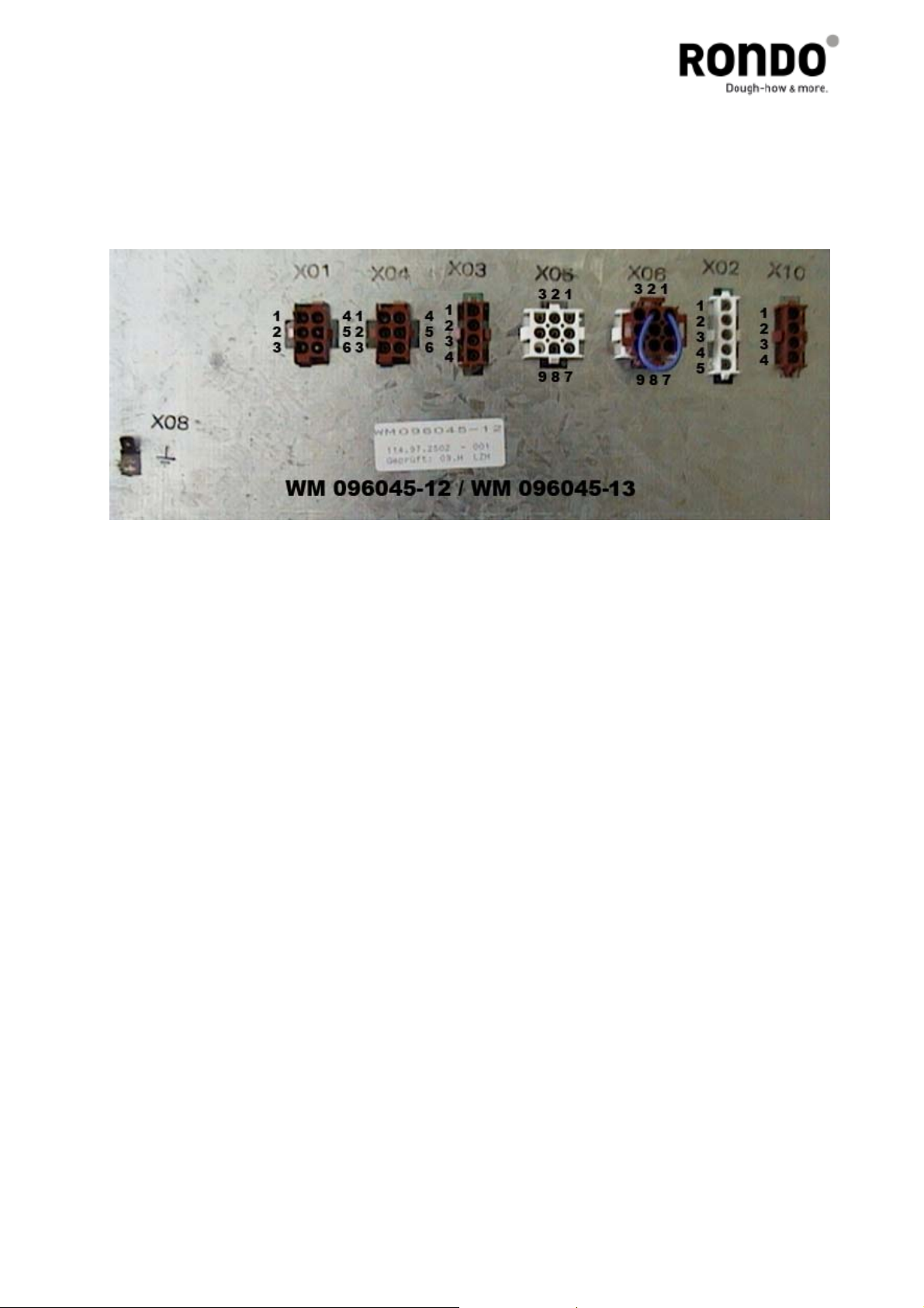
7.3.4 Measure of the voltage on the plugs
All connections to the basic module are plugable and allow a quick and faultless exchange.
The following picture shows the numbering of the plug connections. Based on these, in
combination with the diagram, the output voltage on the basic module can be
measured.
7.4 Important notes to the frequency inverter
7.4.1 Types
For 200 - 230 V and 380 - 460 V different types of frequency inverters and mains
filters are used.
7.4.2 Parameterization
The frequency inverters delivered by RONDO Burgdorf AG, CH are already
parameterized. The inverters can be used without a change for the sheeting
machine Compas SFA612.
Important: All other parameters must not be changed.
______________________________________________________________________________________________________________________________________________________________________________________________________
Edition: 06.2011 Service manual
Page 29

____________________________________________________________________________________________________________________________________________________________________________________________________________________
7.4.3 Ground fault interrupter can be actuated when inverter is started
Leakage current flows through the inverter.
The inverter performs internal switching. Therefore, a leakage current flows through the
inverter. This leakage current may actuate the ground fault interrupter, shutting the power
off.
Use a ground fault interrupter with a high leakage-current detection value (sensitivity
amperage of 200mA or more, operating time of 0,1 s or more) or one with high-frequency
countermeasures for inverter use.
In addition, remember that a leakage current increases in proportion to the cable length.
Normally, approximately 5 mA of leakage current is generated for each meter of cable.
______________________________________________________________________________________________________________________________________________________________________________________________________
Edition: 06.2011 Service manual
Page 30

8. Teilebezeichnungen, Zeichnungen / Désignations des pièces,
dessins / Part names, drawings
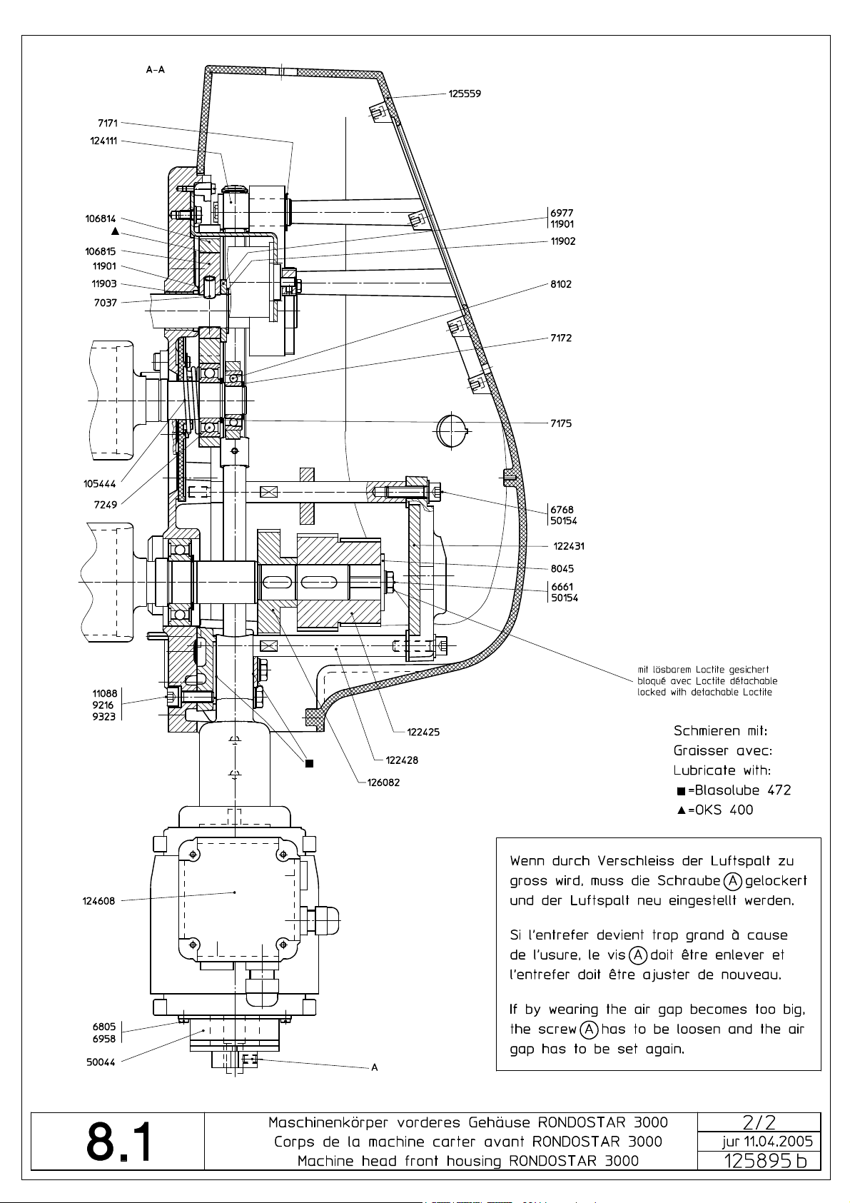
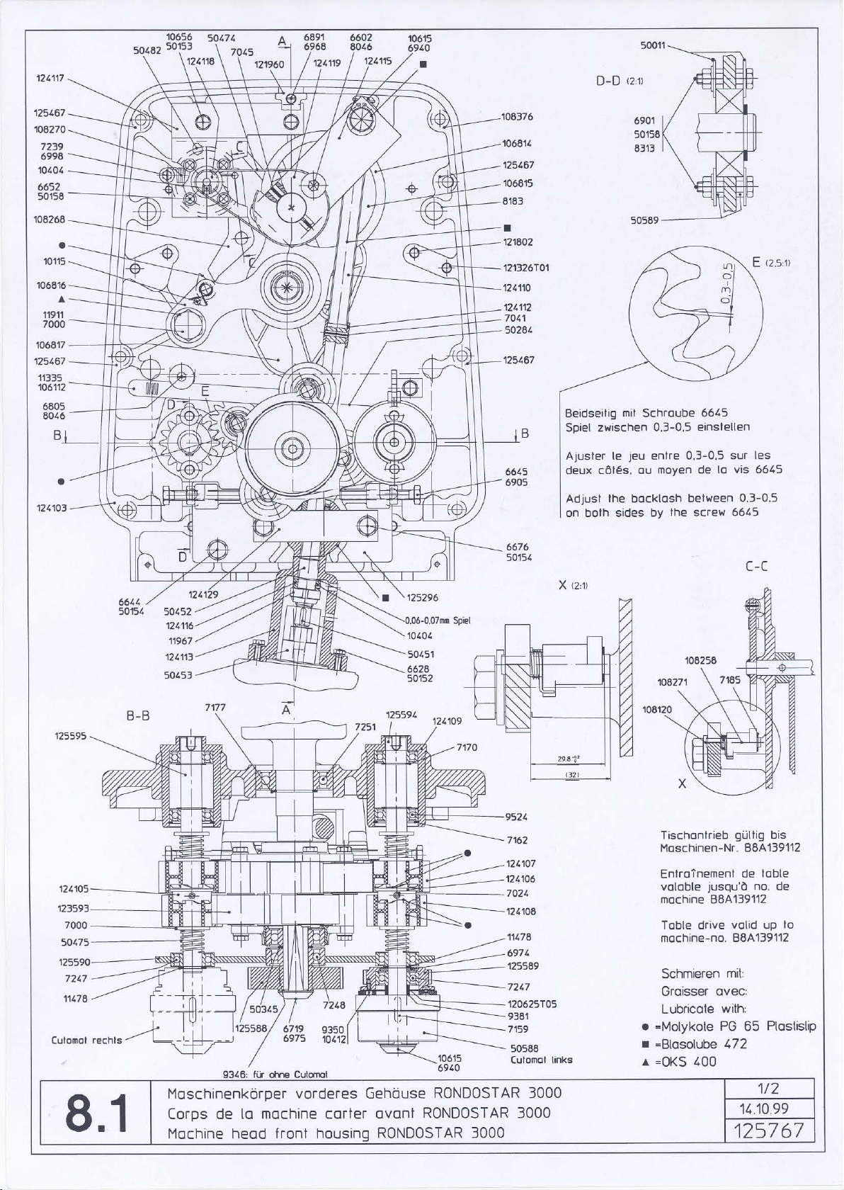
8.1 Maschinenkörper vorderes Gehäuse Corps de la machine carter avant 125895 Machine head front housing
Bestell-Nr.
No commande
Ordering no.
7153 Federkeil 8x25 Clavette 8x25 Key 8x25
7159 Federkeil 5x5x20 Clavette 5x5x20 Key 5x5x20
7249 Rillenkugellager Roulement à billes Ball bearing
7251 Rillenkugellager Roulement à billes Ball bearing
7272 Rillenkugellager Roulement à billes Ball bearing
7286 Rillenkugellager Roulement à billes Ball bearing
8102 Rillenkugellager Roulement à billes Ball bearing
10404 Gewindestift M4x4 Vis sans tête Set screw
11301 Kugellager Freilauf Roulement à billes libre Free wheeling with ball bearing
11335 Senderkopf Tête de transmetteur Transmitter head
11901 Distanzscheibe Rondelle d'espacement Spacing washer
11903 Lagerbüchse Coussinet Bearing bush
50044 El. Magnetbremse Frainage Brake
50283 Zahnriemen GT Courroie dentée GT Toothed belt GT
50284 Zahnriemen GT Courroie dentée GT Toothed belt GT
50451 Federkeil 4x4x14 Clavette 4x4x14 Key 4x4x14
50452 Lagerbüchse mit Bund Coussinet Bearing bush
50453 Wellenkupplung Dispositif d'accouplement Clutch
50474 Zahnriemen HTD Courroie dentée HTD Toothed belt HTD
50482 Absolutwertgeber mit
105444 Druckfeder Ressort à pression Compression spring
106112 Lichtschrankenkabel Câble pour cellule
106114T01 Kupplung mit Kabel Embrayage avec câble Clutch with cable
106814 Verstellschwinge Levier basculant Adjusting lever
106815 Exzenter Excentrique Eccentric
106817 Dichtteller Disque de joint Seal cover plate
122421 Kupplungswelle links Arbre d'embrayage à gauche Clutch shaft left
122422 Kupplungswelle rechts Arbre d'embrayage à droite Clutch shaft right
122423 Riemenscheibe Z=34 Poulie Z=34 Pulley Z=34
122425 Riemenscheibe Z=38/Z=44 Poulie Z=38/Z=44 Pulley Z=38/Z=44
122427 Riemenscheibe Z=46 Poulie Z=46 Pulley Z=46
122428 Distanzbolzen Bouton d'écartement Distance bolt
122431 Lagerbrille Plaque de palier Bearing plate
124110 Spindel Broche Spindle
124111 Mutter Ecrou Nut
124113 Spindellager Logement du broche Spindle bearing
124115 Hebel Levier Lever
124118 Riemenscheibe Z=21 Poulie Z=21 Pulley Z=21
124119 Riemenscheibe Z=65 Poulie Z=65 Pulley Z=65
124608 Motor für Walzenzustellung Moteur pour approche des
126050 Lager Palier Bearing
126063 Spindelhalterung Broche d'appui Holding device
Teilebezeichnung
Désignation
Part name
Stecker
Codeur en valeur absolue
avec prise mâle
photoélectrique.
cylindres
Rotary encoder with plug
Cable for light barrier
Motor for roller adjustment
Page 31

Page 32
Page 33
Page 34

Page 35

8.1 Maschinenkörper vorderes Gehäuse Cutomat / Verbund Corps de la machine carter avant Cutomat / Compoundage 126576 Machine head front housing Cutomat / Compound
Bestell-Nr.
No commande
Ordering no.
7159 Federkeil Clavette Key
7247 * Rillenkugellager Roulement à billes Ball-bearing
7248 Rillenkugellager Roulement à billes Ball bearing
7249 Rillenkugellager Roulement à billes Ball bearing
7251 Rillenkugellager Roulement à billes Ball bearing
8102 Rillenkugellager Roulement à billes Ball bearing
9524 Rillenkugellager Roulement à billes Ball bearing
10404 Gewindestift M4x4 Vis sans tête M4x4 Set screw M4x4
11335 Senderkopf Tête de transmetteur Transmitter head
11901 Distanzscheibe Rondelle d'espacement Spacing washer
11903 Lagerbüchse Coussinet Bearing bush
50044 Bremse Frainage Brake
50284 * Zahnriemen Courroie dentée Toothed belt
50451 Federkeil Clavette Key
50452 Lagerbüchse Coussinet Bearing bush
50453 Kupplung Disp. d'accouplement Clutch
50474 Zahnriemen Courroie dentée Toothed belt
50475 Druckfeder Ressort à pression Compression spring
50482 Absolutwertgeber Codeur en valeur absolue Rotary encoder
50553 Sicherungsring f.Welle Circlips pour arbre Circlip for shaft
50588 * Elektrische Kupplung Embrayage électrique Electrical clutch
105444 Druckfeder Ressort à pression Compression spring
106112 Lichtschrankenkabel Câble pour cell. photoélectr. Cable for light barrier
106814 Verstellschwinge Levier basculant Adjusting lever
106815 Exzenter Excentrique Eccentric
106817 Dichtteller Disque de joint Seal cover plate
123568 Zahnrad Z=22 Roue dentée Z=22 Gearwheel Z=22
123570 Zahnrad Z=15 Roue dentée Z=15 Gearwheel Z=15
123573 Achse Arbre Shaft
124107 Zahnrad Z=18 Roue dentée Z=18 Gearwheel Z=18
124108 Zahnrad Z=16 Roue dentée Z=16 Gearwheel Z=16
124110 Spindel Broche Spindle
124111 Mutter Ecrou Nut
124113 Spindellager Logement du broche Spindle bearing
124115 Hebel Levier Lever
124116 Lagerring Bague Ring
124118 Riemenscheibe Z=21 Poulie Z=21 Pulley Z=21
124119 Riemenscheibe Z=65 Poulie Z=65 Pulley Z=65
124137 Satellitenplatte Disque Disc
124608 Motor für Walzenzustellung Moteur pour approche des
124802 Zahnrad Z=15 Roue dentée Z=15 Gearwheel Z=15
125296 Spindelhalterung Broche d'appui Holding device
125588 * Zahnriemenrad Z=48 Roue courroie dentée Z=48 Pulley Z=48
125589 * Riemenscheibe Z=35 Poulie Z=35 Pulley Z=35
125590 Verbindungsplatte Plaque d'appui Bearing plate
125594 * Kupplungswelle Arbre d'embrayage Clutch shaft
125595 Kupplungswelle Arbre d'embrayage Clutch shaft
125850 Vorderes Gehäuse Carter avant Front housing
134615 Kupplungsscheibe links Roue libre gauche Free-wheel left
134616 Kupplungsscheibe rechts Roue libre droite Free-wheel right
* = Ausführung Cutomat / Version Cutomat / Type Cutomat
Teilebezeichnung
Désignation
Part name
Motor for roller adjustment
cylindres
Page 36

Page 37

Page 38

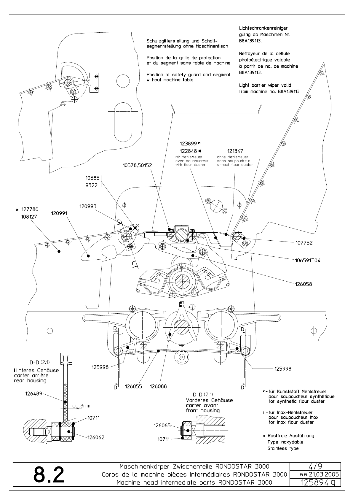
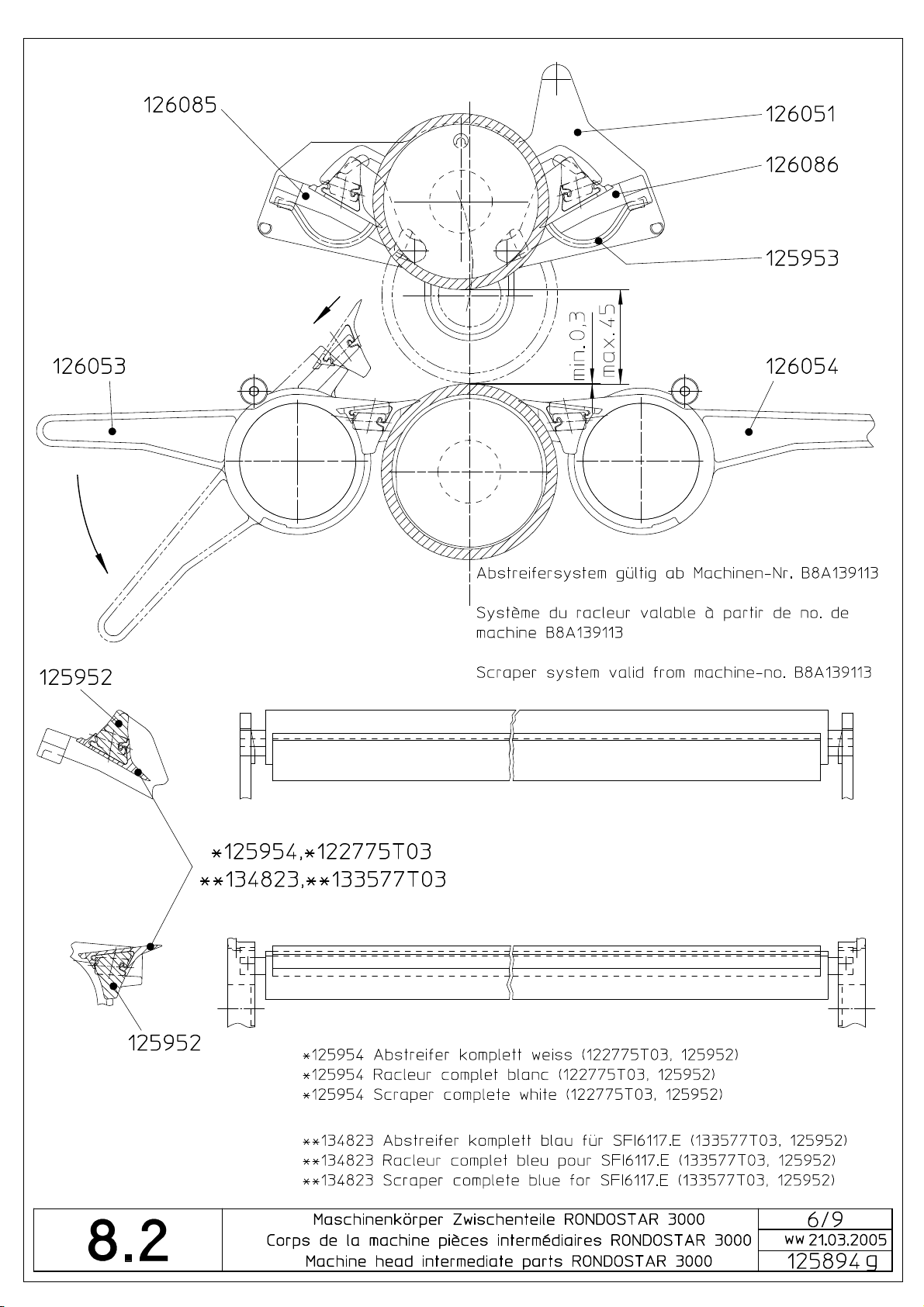
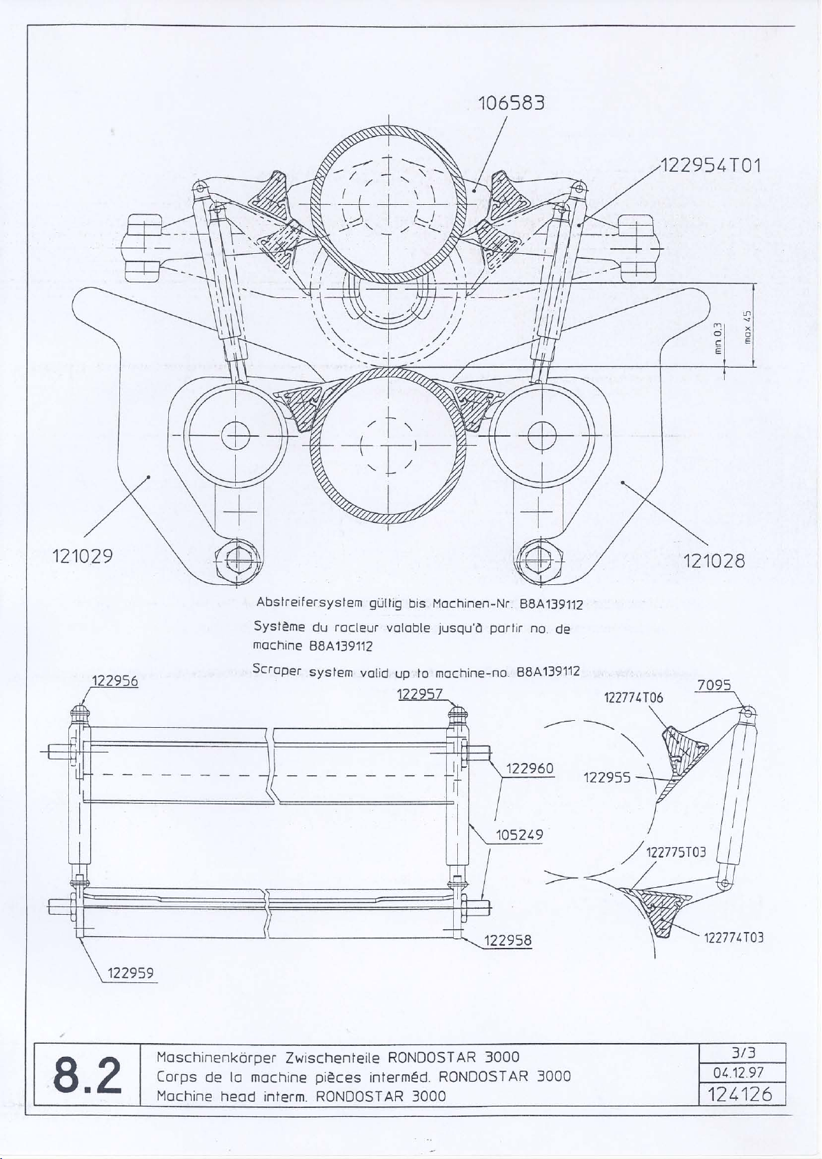
8.2 Maschinenkörper Zwischenteile Corps de la machine pièces intermédiaires 125894 Machine head intermediate parts
Bestell-Nr.
No commande
Ordering no.
8836 Spiral-Druckfeder Ressort à boudin Spiral compression spring
50692 Rillenkugellager Roulement à billes Ball bearing
50693 V-Sicherungsring für Welle
50694 V-Sicherungsring für Bohrung
107752 Arretierungsblech Tôle d'arrêt Locking sheet metal
108127 Schutzgitter Grille de sécurité Safety guard
120719T03 Hülse Douille Bush
120991 Tischhaken Crochet de la table Table-hook
120993 Halteblech Tôle de retenue Retaining sheet metal
121347 Abdeckblech Tôle de couverture Covering metal sheet
122775T03 Abstreifermesser Lame de racleur Scraper blade
122848 Abdeckblech für Inox-
123899 Abdeckblech für Kunststoff-
125593 Unterwalze Rouleau inférieur Lower roller
125872 Oberwalze Rouleau superieur Upper roller
125952 Abstreiferhalter Support pour lame de racleur Scraper blade support
125953 Feder Ressort Spring
125954 Abstreifer komplett Racleur complet Scraper complete
125998 Klinke Cliquet Catch
126051 Seitenplatte hinten Plaque latérale arrière Side-plate rear
126052 Seitenplatte vorne Plaque latérale avant Side-plate front
126053 Spannhebel links Levier de serrage gauche Tension lever left
126054 Spannhebel rechts Levier de serrage droite Tension lever right
126055 Federstab Barre pour ressort Spring bar
126058 Parallelführung Guide parallèle Guide parallel
126062 Bolzen hinten Boulon arrière Bolt, rear
126064 Halter Support Holder
126065 Bolzen vorne Boulon avant Bolt, front
126081 Unterwalze Rouleau inférieur Lower roller
126084 Rakel Racle Ductor
126085 Halter links Support gauche Holder left
126086 Halter rechts Support droite Holder right
126088 Wischer Bras de monture d'essuie Wiper arm
127780 Schutzgitter Inox Grille de sécurité Inox Safety guard Inox
133577T03 Abstreifermesser Lame de racleur Scraper blade
134823 Abstreifer komplett blau Racleur complet bleu Scraper complete blue
Teilebezeichnung
Désignation
Part name
30x1,5
47x1,75
Mehlstreuer
Mehlstreuer
V-Circlip pour arbre 30x1,5 Circlip for shaft 30x1,5
V-Circlip pour alésage
47x1,75
Tôle de couverture pour
saupoudreur Inox
Tôle de couverture pour
saupoudreur synthétique
Circlip for bore 47x1,75
Covering metal sheet for
Inox flour duster
Covering metal sheet for
synthetic flour duster
Page 39
Page 40

Page 41
Page 42

Page 43

Page 44
Page 45

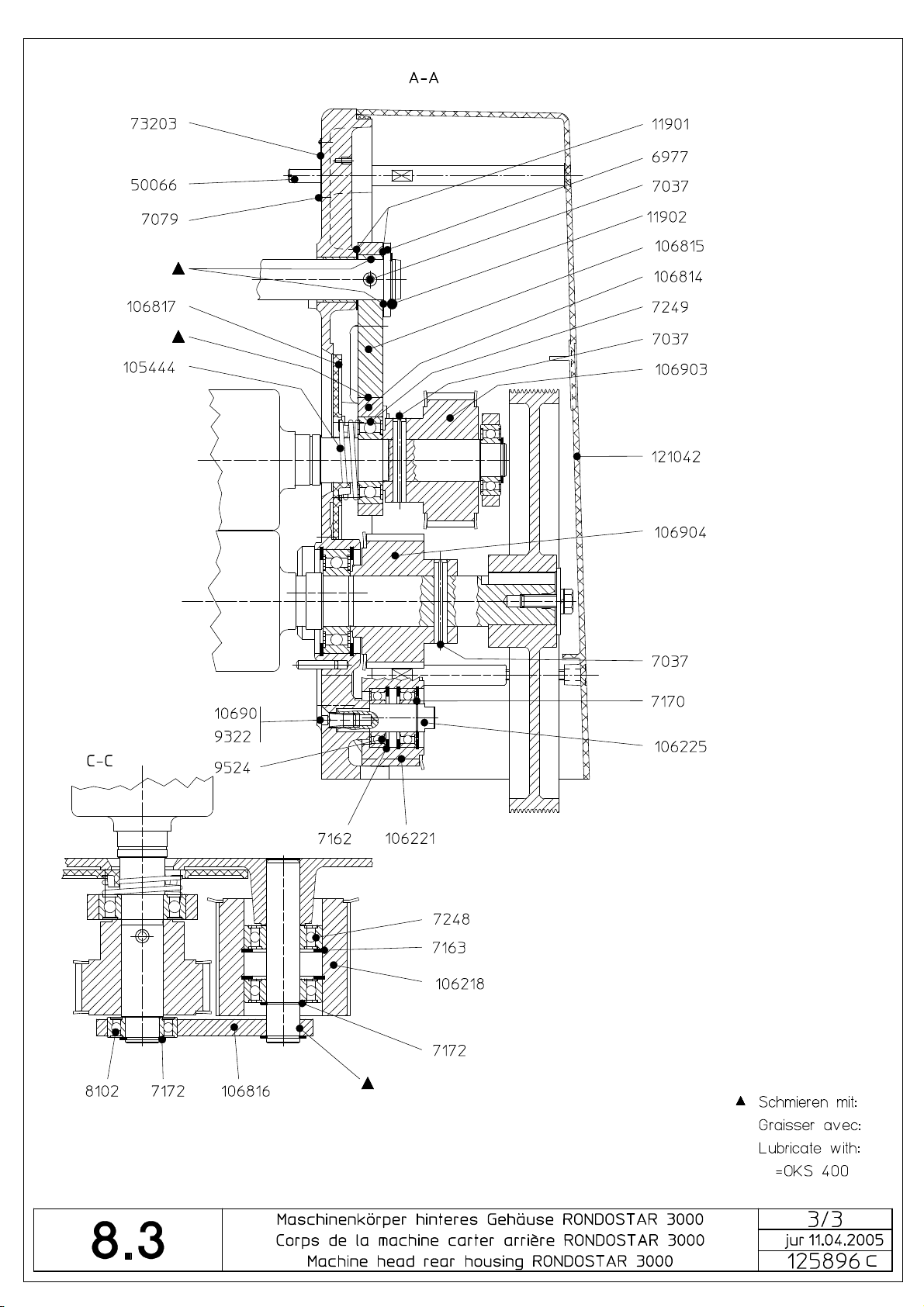
8.3 Maschinenkörper hinteres Gehäuse Corps de la machine carter arrière 125896 Machine head rear housing
Bestell-Nr.
No commande
Ordering no.
7037 Spannhülse Douille de serrage Clamping sleeve
7166 Sicherungsring Circlips Circlip
7248 Rillenkugellager Roulement à billes Ball bearing
7249 Rillenkugellager Roulement à billes Ball bearing
8102 Rillenkugellager Roulement à billes Ball bearing
8722 Halter Support Holder
9371 Endschalter Interr. fin de course Limit switch
9524 Rillenkugellager Roulement à billes Ball bearing
10185 Kabelbinder Colzon Cable binder
11334 Empfängerkopf Tête de récepteur Receiver head
11901 Distanzscheibe Rondelle d'espacement Spacing washer
11935 Zahnriemen Courr. dentée Toothed belt
11936 Doppelzahnriemen Courr. dentée double Double toothed belt
12021 Kabelbride Bride Clamp
12061 Schneckengetriebe-Motor Moteur d'engrenage de la vis
50056 Gewindestift M4x5 Vis sans tête M4x5 Set screw M4x5
50108 Gewindestift Vis sans tête Set screw
100423T05 Kabelbrücke Jonction de cable Cable link
105444 Druckfeder Ressort à pression Compression spring
106111 Lichtschrankenkabel Câble pour cell.photoélectr. Cable for light-barrier
106218 Riemenscheibe Poulie Pulley
106221 Riemenscheibe Poulie Pulley
106225 Exzenter Excentrique Eccentric
106593 Schaltsegment Segment Segment
106812 Winkel Angle Bracket
106814 Verstellschwinge Levier basculant Adjusting lever
106815 Exzenter Excentrique Eccentric
106816 Horizontalschwinge Levier horizontale Horizontal lever
106817 Dichtteller Disque de joint Seal cover plate
106903 Riemenscheibe Poulie Pulley
106904 Riemenscheibe Poulie Pulley
108240 Lagerbolzen Boulon d'arrêt Spring holding bolt
108241 Schraubendruckfeder Ressort à pression Compression spring
108359 Deckel hinten Couvercle arrière Rear cover
120978 Lagerschraube Vis Bolt
120979T01 Distanzbolzen Bouton d'écartement Distance bolt
120979T02 Distanzbolzen Bouton d'écartement Distance bolt
121016T03 Kabel zu Schutzgitter Câble pour grille de séc. Cable for safety guard
121017T01 Kabel zu Mehlstreuermotor Câble pour moteur
121042 Deckel hinten Couvercle arrière Rear cover
121057 Abdeckung Couverture Covering
121069 Zwischenscheibe Disque intermédiaire Intermediate disc
121070 Mitnehmer Entraîneur Catch
122516 Platte Plaque Plate
126066 Gehäuse hinten mit Einpress-
Teilebezeichnung
Désignation
Part name
Worm gear motor
sans fin
Cable for flour duster.-motor
saupoudreur à farine
Carter arrière Rear housing
teile
Page 46

Page 47

Page 48
Page 49

8.4 Unterbauten
Socles
Machine bases
8.4.1 Unterbau
Socle 125787
Machine base
Bestell-Nr.
No commande
Ordering no.
7668 Kabeltülle Passe-câble Cable grommet
7856 Fiberscheibe Rondelle Washer
9211 Sechskantmutter
9286 * Lenkrolle 80x115 Galet-guide 80x115 Guide roll 80x115
9322 Schutzstopfen Bouchon de protection Protection plug
10309 Lenkrolle 80x118 Galet-guide 80x118 Guide roll 80x118
10310 Bockrolle ø 80 Galet fixe ø 80 Frame caster ø 80
10520 Haltering Anneau de blocage Retaining ring
11341 (*) Scheibe Polyamid Disque Polyamid Disc Polyamid
11398 Kabeltülle Passe-câble Cable grommet
11938 Federkeil 8X40 Clavette 8X40 Key 8X40
50603 Motor 1,1 kW 50/60 Hz Moteur 1,1 kW 50/60 Hz Motor 1,1 kW 50/60 Hz
50607 Rippenband Poulie Ribbed belt
50805 * Bockrolle ø 80 Galet fixe ø 80 Frame caster ø 80
51309 Motor 1,1 kW 60 Hz, UL Moteur 1,1 kW 60 Hz, UL Motor 1,1 kW 60 Hz, UL
99259 Lenkrolle komplett Roulette de transport compl. Transport caster compl.
99261 Klinke Cliquet Catch
99264 Achse Axe Axle
99265 Welle Arbre Shaft
99265T02 * Welle Arbre Shaft
99269 Fuss Pied Foot
99528 Ueberstülppuffer Butoir Puffer
108398 Mäuseblech Protection Protection
108880 * Mäuseblech Protection Protection
120725 * Führungsschiene Guidage Guide
120726 * Abdeckung Couverture Covering
120733 Führungsschiene Guidage Guide
120734 Abdeckung Couverture Covering
120753T02 * Tischstütze 6 Support de table 6 Table support 6
120754T01 Tischstütze 6 Support de table 6 Table support 6
120759T02 Verstärkung Renforcement Reinforcement
121414 Schutzbügel Poignée Guard tube
122758 Tischstütze mit Fuss Support de table avec pied Table support with foot
122759 * Tischstütze mit Fuss Support de table avec pied Table support with foot
122761 (*) Gleiter Coulisse Slider
123040 (*) Schneidewellenhalter Porte rouleau de découpe Cutting roller holder
125786 Kasten komplett Boîtiers compl. Box complete
125908 Rippenbandscheibe Poulie Ribbed V-belt pulley
125909 Rippenbandscheibe Poulie Ribbed V-belt pulley
125910 Rippenbandscheibe Poulie Ribbed V-belt pulley
125911 Motorhalterung Fixation du moteur Motor mounting
125912 Spannwinkel Angle tendeur Fastening bracket
125940 * Kasten komplett Boîtiers compl. Box complete
126818 * Lenkrolle komplett Roulette de transport compl. Transport caster compl.
Teilebezeichnung
Désignation
Part name
selbstsichernd M8x8
Ecrou hexagonal
indesserable
M8x8
Nut hexagon self locking
M8x8
Page 50

Page 51

Page 52

8.4.2 Unterbau mit Ausleger Socle avec support 129160 Machine base with support
Bestell-Nr.
No commande
Ordering no.
9211 Sechskantmutter
9286 Lenkrolle 80 x 115 Galet-guide 80 x 115 Guide roll 80 x 115
11341 Scheibe Polyamid Disque Polyamid Disc Polyamid
92233 * Halter für Schneidewellen-
102526T07 Distanzstab Barre d‘espacement Distance bar
122761 Gleiter Coulisse Slider
125466 * Maschinentisch Cutomat,
128701 Stütze komplett Support complet Support complete
128703 Halter Support Holder
129159 Ausleger komplett Bras complet Bracket complete
129414 * Stütze komplett Cutomat Support complet Cutomat Support complete Cutomat
129415 * Strebe Contre-fiche Stanchion
Teilebezeichnung
Désignation
Part name
selbstsichernd M8 x 8
ablage
rechts/links
Ecrou hexagonal
indesserable
M8 x 8
Support pour rouleau de
découpe
Table de machine Cutomat,
droite/gauche
Nut hexagon self locking
M8 x 8
Holder for storage for
cutting roller
Machine table Cutomat,
right/left
Page 53

Page 54

8.4.3 Unterbau Rondostar SFI Socle Rondostar SFI 125899 Machine base Rondostar SFI
Bestell-Nr.
No commande
Ordering no.
6918 Springmutter 5.5x20 Ecrou 5.5x20 Nut 5.5x20
9211 Sechskantmutter selbst-
9286 Lenkrolle 80x1 Galet-guide 80x1 Guide roll 80x1
10520 Haltering Anneau de blocage Retaining ring
10927 Gumminippel Nipple de caoutchouc Rubber nipple
11938 Federkeil 8x40 Clavette 8x40 Key 8x40
50603 Motor 1,1 kW 50/60 Hz Moteur 1,1 kW 50/60 Hz Motor 1,1 kW 50/60 Hz
50607 Rippenband Courroie striée Ribbed-belt
51309 Motor 1,1 kW 60 Hz, UL Moteur 1,1 kW 60 Hz, UL Motor 1,1 kW 60 Hz, UL
99264 Achse Axe Axle
99528 Ueberstülppuffer Butoir Puffer
121095 Teigfangblech Tôle réceptrice Dough catch pan
125908 Rippenbandscheibe ø = 255 Poulie courroie striée ø = 255 Ribbed V-belt pulley ø = 255
125909 Rippenbandscheibe ø = 30 Poulie courroie striée ø = 30 Ribbed V-belt pulley ø = 30
125910 Rippenbandscheibe ø = 36 Poulie courroie striée ø = 36 Ribbed V-belt pulley ø = 36
125911 Motorhalterung Fixation du moteur Motor mounting
125912 Spannwinkel Angle tendeur Fastening bracket
125984 Abdeckung vorne Couverture avant Frontcovering
125985 Abdeckung hinten Couverture arrière Rearcovering
125986 Kasten komplett Boîtiers complet Box complete
125987 Ausleger komplett Support complet support complete
125990 Bügel komplett Etrier complet Bow complete
125991 Achse Axe Axle
126056 Tischstütze Support de table Table support
126059 Tischstütze Support de table Table support
126060 Untertisch komplett Table inférieure complete Lower table complete
126068 Halter Support Holder
126069 Führung Guide Guide
126070 Klinke Cliquet Catch
Teilebezeichnung
Désignation
Part name
sichernd M8x8
Ecrou hexagonal
indesserable M8x8
Nut hexagon self locking
M8x8
Page 55

Page 56

Page 57

Page 58

8.5 Maschinentische Tables de machine Machine tables
8.5.1 Maschinentisch Inox zu Cutomat Table de machine Inox pour Cutomat 126574 Machine table Inox to Cutomat
Bestell-Nr.
No commande
Ordering no.
5105 Führung Guide Guide
7247 Rillenkugellager Roulement à billes Ball bearing
7286 Rillenkugellager Roulement à billes Ball bearing
50902 Sicherungsring für Welle Circlips pour arbre Circlip for shaft
91339T05 Antriebsrolle Rouleau d'entraînement Drive roller
99090 Scheibe Disque Disc
121093 Teigrückhaltebügel Archet de retenue de pâte Dough retaining hoop
121096 Handschutz Inox Protège-mains Inox Hand safety guard Inox
121286 Haspelhalter Support enrouleur Dough reeler bracket
121344 Kunststoffband 640 x 3570 Tapis 640 x 3570 Conveyor belt 640 x 3570
121344T02 Kunststoffband 640 x 2680 Tapis 640 x 2680 Conveyor belt 640 x 2680
125996 Lagerkappe Palier Bearing
125997 Rollenhalter Support de rouleau Roller bracket
126886T02 Teighaspel 65 Enrouleur à pâte 65 Dough reeler 65
131340T01 Rollenachse Arbre Shaft
131345T06 Leerlaufrolle
134695 Maschinentisch 65 Inox
134696 Rollenhalter Inox Support de rouleau Inox Roller bracket Inox
135694 Maschinentisch 65 plus Inox Table de machine 65 plus
139241 Tischverstärkung Renforcement de table Table reinforcement
Teilebezeichnung
Désignation
Part name
inkl. Rillenkugellager
für Cutomat
Rouleau à vide
incl. Roulement à billes
Table de machine 65 Inox
pour Cutomat
Inox
Idle roller
incl. Ball bearing
Machine table 65 Inox
to Cutomat
Machine table 65 plus Inox
Page 59
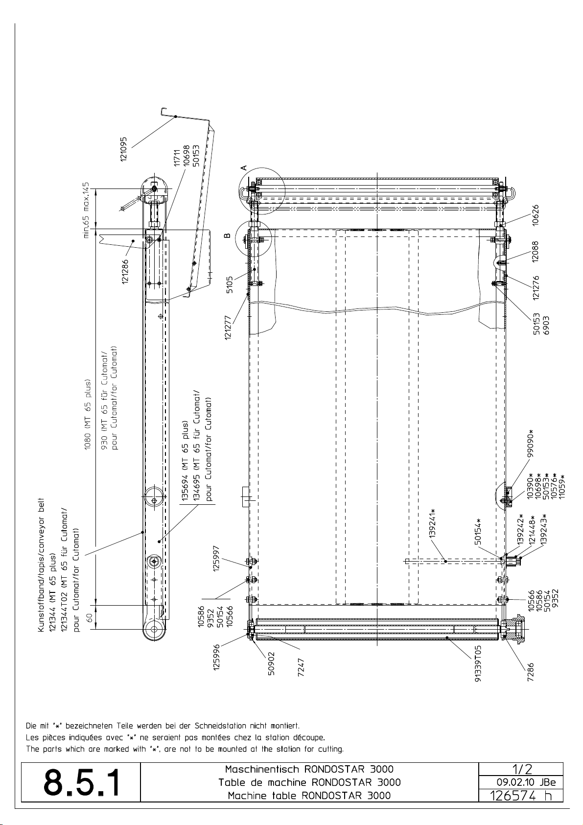
Page 60

Page 61

8.5.2 Maschinentisch Inox zu Auslegermodell Table de machine Inox pour modèle support 134821 Machine table Inox to support type
Bestell-Nr.
No commande
Ordering no.
5105 Führung Guide Guide
7247 Rillenkugellager Roulement à billes Ball bearing
7286 Rillenkugellager Roulement à billes Ball bearing
50902 Sicherungsring für Welle Circlips pour arbre Circlip for shaft
52228 Rillenkugellager Roulement à billes Ball bearing
91339T05 Antriebsrolle Rouleau d'entraînement Drive roller
99090 Scheibe Disque Disc
105467 Kunststoffband
121093 Teigrückhaltebügel Archet de retenue de pâte Dough retaining hoop
121096 Handschutz Inox Protège-mains Inox Hand safety guard Inox
121286 Haspelhalter Support enrouleur Dough reeler bracket
125996 Lagerkappe Palier Bearing
125997 Rollenhalter Support de rouleau Roller bracket
126886T02 Teighaspel 65 Enrouleur à pâte 65 Dough reeler 65
131340T01 Rollenachse Arbre Shaft
131345T06 Leerlaufrolle
134495 Maschinentisch geschweisst,
134719 Rollenhalter Support de rouleau Roller bracket
135341 Kunststoffband blau
Teilebezeichnung
Désignation
Part name
640 x 3280
inkl. Rillenkugellager
Inox
640 x 3280
Tapis synthétique
640 x 3280
Rouleau à vide
incl. Roulement à billes
Table de machine soudée,
Inox
Tapis synthétique bleu
640 x 3280
Synthetic conveyor belt
640 x 3280
Idle roller
incl. Ball bearing
Machine table welded, Inox
Synthetic conveyor belt blue
640 x 3280
Page 62

Page 63

Page 64

8.5.3 Maschinentisch Inox zu Sockelmodell Table de machine Inox pour modèle socle 135551 Machine table Inox to socle type
Bestell-Nr.
No commande
Ordering no.
5105 Führung Guide Guide
7247 Rillenkugellager Roulement à billes Ball bearing
7286 Rillenkugellager Roulement à billes Ball bearing
50902 Sicherungsring für Welle Circlips pour arbre Circlip for shaft
52228 Rillenkugellager Roulement à billes Ball bearing
91339T05 Antriebsrolle Rouleau d'entraînement Drive roller
99090 Scheibe Disque Disc
105467 Kunststoffband
121093 Teigrückhaltebügel Archet de retenue de pâte Dough retaining hoop
121096 Handschutz Inox Protège-mains Inox Hand safety guard Inox
121286 Haspelhalter Support enrouleur Dough reeler bracket
125996 Lagerkappe Palier Bearing
125997 Rollenhalter Support de rouleau Roller bracket
126886T02 Teighaspel 65 Enrouleur à pâte 65 Dough reeler 65
131340T01 Rollenachse Arbre Shaft
131345T06 Leerlaufrolle
134495 Maschinentisch 67 Inox Table de machine 67 Inox Machine table 67 Inox
134691 Rollenhalter Inox Support de rouleau Inox Roller bracket Inox
135341 Kunststoffband blau
139241 Tischverstärkung Renforcement de table Table reinforcement
Teilebezeichnung
Désignation
Part name
640 x 3280
inkl. Rillenkugellager
640 x 3280
Tapis synthétique
640 x 3280
Rouleau à vide
incl. Roulement à billes
Tapis synthétique bleu
640 x 3280
Synthetic conveyor belt
640 x 3280
Idle roller
incl. Ball bearing
Synthetic conveyor belt blue
640 x 3280
Page 65

Page 66

Page 67

8.5.4 Mehlfangblech Tôle réceptrice pour farine 95738 Flour catch pan
Bestell-Nr.
No commande
Ordering no.
91988 Platte Plaque Plate
91992T15 Fangblech 67 Tôle réceptrice 67 Catch pan 67
91992T17 Fangblech Cutomat Tôle réceptrice Cutomat Catch pan Cutomat
91992T18 Fangblech 65 Tôle réceptrice 65 Catch pan 65
105385T05 Halter Support Holder
Teilebezeichnung
Désignation
Part name
Page 68

Page 69

8.6 Schneidestation / Maschinentisch Cutomat Station découpe / Table de machine Cutomat 125466 Station for cutting / Machine table Cutomat
Bestell-Nr.
No commande
Ordering no.
7167 Sicherungsring für Welle
7170 Sicherungsring für Welle
7246 Rillenkugellager 6201 2RS Roulement à billes 6201 2RS Ball bearing 6201 2RS
7512 Rillenkugellager 6304 2RS Roulement à billes 6304 2RS Ball bearing 6304 2RS
9365 Zyl.Schraube m.
9524 Rillenkugellager 6003 2RS Roulement à billes 6003 2RS Ball bearing 6003 2RS
11571 Distanzbolzen 6Kt. M6x55 Bouton d'écartement hexagonal
50162 Gasfeder 350N Ressort pneumatique 350N Gas spring 350N
50277 Passkerbstift 5x60 Goupille cann.d'ajustage à
83273T05 Rolle Stahl Rouleau en acier Steel cylinder
99090 Scheibe Disque Disc
101507 Führung Guide Guide
107751T03 Schaltstab Axe Rod
107752 Arretierungsblech Tôle d'arrêt Locking sheet metal
121332 Mitnehmer Entraîneur Catch
121334T01 Torsionsfeder Ressort à torsion Torsion spring
121334T02 Torsionsfeder Ressort à torsion Torsion spring
121337 Rastsegment Segment cranté Catch segment
121339 Hülse Douille Husk
121340T02 Welle Arbre Shaft
122828 Verstärkung Renforcement Reinforcement
122945T01 Achse Axe Axle
122945T04 Achse Axe Axle
122946 Schutzblech vorne Tôle de protection avant Front protection plate
122967 Seitenplatte komplett,
122968 Seitenplatte komplett
122985 Lasche komplett Collier de fixation complet Bracket complete
123061 Schutzgitter komplett Grille de sécurité complete Safety guard complete
123219 Hebel linke Ausführung
123278 Schutzblech Tôle de protection Protection plate
123691 Hebel lang Levier longue Lever long
123692 Hebel kurz Levier court Lever short
123693 Nabe Moyen Hub
123697 Verstärkung Renforcement Reinforcement
123702 Hebel kurz, rechts Levier court, droite Lever short, right
124690 Nutenstein Coulisseau Sliding block
125459 Büchse Douille Bush
125462 Drehherz Toc du tour Driving dog
125463 Zahnsegment Segment denté Toothed quadrant
126574 Maschinentisch 65 Table de machine 65 Machine table 65
127796 Schutzgitter komplett Inox Grille de sécurité complete Inox Safety guard compl. Inox
128109 Federführung mit Lager Guidage de ressort avec palier Spring guide with bearing
128332 Hebel komplett Levier complet Lever complete
135589 Schutzblech hinten Tôle de protection arrière Rear protection plate
Teilebezeichnung
Désignation
Part name
12x1
17x1
Innensechskant M8x12
hinten
vorne
komplett
Circlips pour arbre 12x1 Circlip for shaft 12x1
Circlips pour arbre 17x1 Circlip for shaft 17x1
Vis cylindrique avec tête
hexagonal M8x12
M6x55
gorge 5x60
Plaque latérale
complete,arrière
Plaque latérale complete, avant Side plate complete, auterior
Levier gauche complet Lever left complete
Cylinderscrew with hexagon
head M8x12
Distance bolt hexagon
M6x55
Taper-grooved dowel pin
5x60
Side plate complete,
posterior
Page 70

Page 71

Page 72

8.7 Mehlstreuer Inox Saupoudreur à farine Inox 106573 Flour duster Inox
Bestell-Nr.
No commande
Ordering nr
11532 Haltering Anneau de blocage Retaining spring
73264T04 Abstreifermesser Lame de racleur Scraper blade
102224 Hebelarm Bras de levier Arm of a lever
105038T01 Schieber Verrou Slide
105048T03 Schwingblech Tôle basculant Swing sheet
106562T03 Wippe 630 komplett Bascule 630 complete Rocker 630 complete
106566T03 Achse 630 Axe 630 Axle 630
106567 Lager Palier Bearing
106568 Lager Palier Bearing
106570 Exzenterhebel Levier excentrique Eccentric lever
106574T03 Trichter 630 Trémie 630 Hopper 630
106581T03 Bürstenträger 630 Porte brosse 630 Brush holder 630
106582T03 Bürste 630 Brosse 630 Brush 630
107082T03 Mehlstaub-Schutz 630 Protection contre pousse de
120744 Bolzen Boulon Bolt
120745 Hebel Levier Lever
124257T03 Streuwalze
Teilebezeichnung
Désignation
Part name
grobe Randrierung
farine 630
Rouleau distributeur
surface grosse
Protection against flour dust
630
Coarse surface spreading
roller
Page 73

Page 74

8.7 Mehlstreuer Saupoudreur à farine 123336 Flour duster
Bestell-Nr.
No commande
Ordering nr
11532 Haltering Anneau de blocage Retaining spring
102224 Hebelarm Bras de levier Arm of a lever
105048T03 Schwingblech Tôle basculant Swing sheet
106562T03 Wippe 630 Bascule Rocker
106566T05 Achse Axe Axle
106567 Lager Palier Bearing
106568 Lager Palier Bearing
106570 Exzenterhebel Levier excentrique Eccentric lever
107082T03 Mehlstaub-Schutz Prot.contre pousse de farine Protection ag. flour dust
120744 Bolzen Boulon Bolt
120745 Hebel Levier Lever
123790 Schieber Verrou Slide
123791 Trichter Trémie Hopper
123919 Bürstenhalter Porte brosse Brush holder
123920 Federblatt Lame de racleur Scraper blade
123922 Bürste Brosse Brush
123923 Federblatt Lame de racleur Scraper blade
124257 Streuwalze
Teilebezeichnung
Désignation
Part name
grobe Randrierung
Rouleau distributeur
surface grosse
Coarse surface spreading
roller
Page 75

Page 76

8.8 Automatischer Teighaspel Enrouleur automatique 124590 Automatic dough reeler
Bestell-Nr.
No commande
Ordering nr
6815 Senkschraube mit Schlitz
9172 U-Scheibe M12x2 Rondelle Washer
9351 Rillenkugellager Roulement à billes Ball bearing
9756 Lagerbüchse ohne Bund Coussinet Bearing bush
10996 Distanzscheibe 30/42/0.5 Rondelle d'espacement Spacing washer
11352 6kt. Mutter M12x0.5D rostfrei Ecrou hexagonal M12x0,5D Nut hexagon M12x0,5D
11445 6kt. Mutter M8x8
12092 PT-Linsenschraube
50011 U-Scheibe M5x1.2 Rondelle M5x1.2 Washer M5x1.2
50314 Steckereinsatz Insert de prise male Plug insert
50315 Steckereinsatz Insert de prise male Plug insert
50322 Distanzscheibe 12/24x0.5 Rondelle d'ecartement Spacer-washer
50466 O-Ring O-Anneau O-Ring
50468 Rillenkugellager Roulement à billes Ball bearing
50469 Rillenkugellager Roulement à billes Ball bearing
50471 Passschraube m. I6kt. M8x20 Vis spec. M8x20 Screw spez. M8x20
50491 Zyl.Schraube m.I6kt. M4x8 Vis cylindrique avec tête
50564 O-Ring O-Anneau O-Ring
50725 Anbaugehäuse Boîte adaptable Attached housing
50739 Senkschraube M6x16 special Vis à tête conique M6x16
51270 Sockelgehäuse inkl.
51273 Tüllengehäuse inkl.
51334 Kabelverschraubung Passe-câble à vis Screwed cable gland
72750 Schraubendruckfeder Ressort à pression Compression spring
103551T04 Welle Arbre Shaft
108526 Traverse Traverse Tie-bar
124553 Zwischenrad Z=12 Roue intermédiare Z=12 Intermediate wheel Z=12
124554T01 Hülse Douille Husk
124554T02 Hülse Douille Husk
124559 Zwischenplatte Plat intermédiaire Intermediate plate
124560V1 Leerlaufrolle 1 Rouleau à vide 1 Idle roller 1
124561V1 Leerlaufrolle 2 Rouleau à vide 2 Idle roller 2
124562V1 Leerlaufrolle 3 Rouleau à vide 3 Idle roller 3
124563V1 Leerlaufrolle 4 Rouleau à vide 4 Idle roller 4
124564V1 Leerlaufrolle 5 Rouleau à vide 5 Idle roller 5
124565 Schwenkplatte oben links Plaque tournante en haut
124568 Schwenkplatte unten rechts Plaque tournante en bas
124569 Abdeckung Schwenkplatte
124570 Abdeckung Schwenkplatte links Recouvrement gauche Front cover left
124571 Rolle Rouleau Roller
124572 Kupplungsplatte Plaque d'embrayage Clutch-plate
124575T01 Strebe Chandelle Stanchion
124576 Welle Arbre Shaft
124578 Schwenkplatte Plaque tournante Swifel plate
124579 Seitenplatte rechts Plaque latérale droite Side plate right
124582 Bolzen Boulon Bolt
124583 Sicherheitsblech Tôle de sécurité Security plate
Teilebezeichnung
Désignation
Part name
M6x10
selbstsich.rostfrei
m.Kreuzschlitz 5x10
Kabelverschraubung
Kabelverschraubung
rechts
Vis à tête fraisée avec fente
M6x10
Ecrou hexagonal indesserable
M8x8
Vis PT
5x10
hexagonal M4x8
spécial
Boîte de socle incl. passecâble à vis
Boîte de passe-câble incl.
passe-câble à vis
gauche
droite
Recouvrement droite Front cover right
Screw M6x10
Self-locking hexagon nut
M8x8
Screw 5x10
Cylinderscrew with hexagon
head M4x8
Countersunk screw M6x16
special
Base housing incl. screwed
cable gland
Gromment housing incl.
screwed cable gland
Swifel plate above left
Swifel plate below left
Page 77

124584 Schwenkplatte oben rechts
komplett
124585 Schwenkplatte unten links
komplett
124586 Seitenplatte links komplett Plaque latérale gauche
Plaque tournante en haut
complete
Plaque tournante en bas
complete
Swifel plate above right
complete
Swifel plate below left
complete
Side-plate left complete
complete
124587 Antriebsrolle Rouleau d'entraînement Driving roller
124591 Halteplatte Plaque Holding plate
124594 Profil-Strebe Chandelle Stanchion
124595 Motor mit Kabel Linak Moteur avec câble Linak Motor with cable Linak
124595T03 Motor mit Kabel Linak Moteur avec câble Linak Motor with cable Linak
124597 Mitnehmerstift Entraîneur-broche Catch-bolt
126381 Gabel Fourche Forked support
126894 Profilrohr Tube profilé Special section tube
130530 Antriebsrad Z=10 Roue dentée Z=10 Gearwheel Z=10
130531 Antriebsrad Z=12 Roue dentée Z=12 Gearwheel Z=12
130532 Antriebsrad Z=13 Roue dentée Z=13 Gearwheel Z=13
130533 Zwischenrad Z=12 Roue intermédiare Z=12 Intermediate wheel Z=12
Page 78

Page 79

Page 80

8.8.1 Convert the automatical dough reeler from the right to the left machine table
Mechanical modification
- Dismount both machine tables
- Dismount the reeler
- Interchange the drive rollers on both machine tables i. e. drive roller of the existing left table will be new in the right
table mounted, drive roller of the existing right table will be new in the left table mounted.
left table
right table
- Change the table hook on the right side of machine head and the bolt on the right machine table (only SFS, without SFI)
table hook
right
table
- Mount the automatical dough reeler on the left machine table
- Mount both machine tables
bolt
Electrical conversion
- Dismount the front cover of the base.
- On the existing reeler cable dismount the connecting plug to the reeler
- Retract the reeler cable into the base.
- Interchange mutually the blind plug and the rubber funnel for the cable passage in the base front-left / rear-right.
- Extract the reeler-cable front-left through the rubber funnel and lay it to the reeler.
- Reconnect the plug on the reeler cable. Lead No. 1 to connection 1, lead No. 2 to connection 2.
Adjustment of software (modification of the set-up data)
- Put Parameter 10 to 2 (Auto reeler left)
Edition: 08. 1998
Service manual
Page 81

8.8.2 Haspel anheben Rondostar SFI6117.E Soulever l’enrouleur Rondostar SFI6117.E 134825 Reeler raise Rondostar SFI6117.E
Bestell-Nr.
No commande
Ordering no.
50048 Gasfeder 100N ohne
50485 Gasfeder 200N mit
Teilebezeichnung
Désignation
Part name
automatischem Haspel
automatischem Haspel
Vérin à gaz 100N sans
enrouleur automatique
Vérin à gaz 200N avec
enrouleur automatique
Pneumatic spring 100N
without automatic reeler
Pneumatic spring 200N with
automatic reeler
Page 82

Page 83

8.9 Elektrokasten Boîte électrique 108611 Electrical box
Bestell-Nr.
No commande
Ordering no.
8935 Feinsicherung 2,0A träg Fusible 2,0A lent Fuse 2,0A slow
50361 Kleinleistungschütz Contacteur de petit calibre Contactor miniature
50362 Kleinleistungsschütz Contacteur de petit calibre Contactor miniature
50477 Grundmodul Module de base Basic module
50495 Feinsicherung 0,63A träg Fusible 0,63A lent Fuse 0,63A slow
52120 Durchgangsklemme Borne Terminal
52122 Schutzleiterklemme Borne de terre Earth terminal
52124 Abschlussplatte Plaque de fermeture End cover plate
52131 Endklammer Pièce finale End piece
105404 Elektrokasten Boîte électrique Electrical box
105405 Elektrokasten UL Boîte électrique UL Electrical box UL
105406 Deckel Couvercle Cover
105407 Deckel UL Couvercle UL Cover UL
Teilebezeichnung
Désignation
Part name
Page 84

Page 85

8.10 Elektrokasten Cutomat
Boîte électrique Cutomat 108620
Electrical box Cutomat
Bestell-Nr.
No commande
Ordering no.
8935 Feinsicherung 2,0A träg Fusible 2,0A lent Fuse 2,0A slow
50359 Hilfsschalterblock Bloc de contacts auxiliaires Contact block auxiliary
50361 Kleinleistungschütz Contacteur de petit calibre Contactor miniature
50362 Kleinleistungsschütz Contacteur de petit calibre Contactor miniature
50477 Grundmodul Module de base Modul basic
50495 Feinsicherung 0,63A träg Fusible 0,63A lent Fuse 0,63A slow
50604 Zeitrelais Relais temporise Time relais
50628 Dreiphasen-Netzfilter Filter au réseau triphasé Triphase mains filter
52120 Durchgangsklemme Borne Terminal
52122 Schutzleiterklemme Borne de terre Earth terminal
52124 Abschlussplatte Plaque de fermeture End cover plate
52131 Endklammer Pièce finale End piece
105404 Elektrokasten Caisse de commande Control box
105405 Elektrokasten UL Caisse de commande UL Control box UL
105406 Deckel Couvercle Cover
105407 Deckel UL Couvercle UL Cover UL
135202 Frequenzumrichter 230V Variateur de fréquence 230V Frequency inverter 230 V
135203 Frequenzumrichter 400V Variateur de fréquence 400V Frequency inverter 400 V
Teilebezeichnung
Désignation
Part name
Page 86

Page 87

8.11 Vorderer Deckel: Elektrische Ausrüstung Couvercle avant: Equipement électrique 108621 Front cover: Electrical equipment
Bestell-Nr.
No commande
Ordering no.
12036 Kabelbride Bride pour câble Cable clamp
50481 Handrad komplett Roue à main complete Handwheel complete
50483 Drehknopf Bouton tournant Turning knob
50484 Flachbandkabel 20-pol. Câble plat, 20 pol. Ribbon cable, 20 pol.
50587 Prozessoreinheit Unité microprocesseur Microprocessor unit
50925 Pilztaster schwarz Bouton poussoir noir Push button black
50926 Pilztaster rot Bouton poussoir rouge Push button red
50927 Hilfsschalterblock 2S Bloc de contact auxiliaires 2S Contact block auxiliary 2S
50928 Hilfsschalterblock 10 Bloc de contact auxiliaires 10 Contact block auxiliary 10
124606 Speisekabel zu
124607 Kabel zu Tasten Câble pour bouton poussoir Cable for push-button
124609 Kabel zu Tasten Câble pour bouton poussoir Cable for push-button
125559 Vorderer Deckel Couvercle avant Front cover
125563 Blech zu Display Tôle pour display Sheet for display
Teilebezeichnung
Désignation
Part name
Prozessor
Câble d'alimentation.
proceseur
Cable for processor supply
Page 88

Page 89

0
1
2 3 4 5 6 7
RONDO Burgdorf AG
8
9
A
B
C
D
Heimiswilstrasse 42
CH-3400 Burgdorf
Tel.:
Fax:
Webseite:
E-mail:
Anlage
Installation
Installation
=RONST01
+41 (0)34 420 81 11
+41 (0)34 420 81 99
www.rondo-online.com
service a ch.rondo-online.com
Bezeichnung
Designation
Name
Rondostar
Ort
Lieu
Location
+1
+2
+3
Bezeichnung
Designation
Name
Steuerkasten
Coffret de commande
Control box
Steuerkasten Bedienungsfront
Coffret de comm. a la cote operateur
Control box on tending side
an
suronRondostar
A
B
C
D
E
31.03.2010
Plot-Datum:
Änderung
e
b
c
d
34009
32357
32363
32370
Datum
19.10.04
03.09.01.
19.02.02
04.10.2002
Name
Blaser
Spahr
Blaser
Sa
gez.
gepr.
Datum
11.09.97
Name
Ryser
Dough-how & more.
Bez.
Anlagenbez.
Rondostar 3000 , SFS611
Zeichn.-Nr.:
500680e
Auftrag:
Ort:
1
Anlage:
RONST01
Bl:
0
E
Bl.
Page 90

1
BENENNUNG DEUTSCH
POS
BENENNUNG FRANZOESISCH
BENENNUNG ENGLISCH
1 Grundmodul -A1 1.5 50477
Module de base +1 /
Module, basic =RONST01 Ecostar/Rondostar/Kombi
2 3 4 5 6 7
-BMK
+ORT
=ANLAGE
ARTIKEL-NR.
/
AUFTRAGS-NR.
TECHNISCHE DATEN 1
TECHNISCHE DATEN 2
BEMERKUNGEN
POS
17 Prozessoreinheit -A2 1.5 50587
Unite microprocesseur +2 /
Microprocessor unit =RONST01 Rondostar
BENENNUNG DEUTSCH
BENENNUNG FRANZOESISCH
BENENNUNG ENGLISCH
-BMK
+ORT
=ANLAGE
8
BL.PFADBL.PFAD
ARTIKEL-NR.
/
AUFTRAGS-NR.
9
TECHNISCHE DATEN 1
TECHNISCHE DATEN 2
BEMERKUNGEN
10
2 Sicherung traeg -A1/F1 1.6 50495 In=T 0,63A Dm=5x20
Fusible a act. ret. +1 /
Fuse slow =RONST01
3 Sicherung traeg -A1/F2 1.6 8935 In=T 2.0A Dm=5x20
Fusible a act. ret. +1 /
Fuse slow =RONST01
4 Sicherung traeg -A1/F3 1.6 8935 In=T 2.0A Dm=5x20
Fusible a act. ret. +1 /
Fuse slow =RONST01
5 Kleinleistungsschuetz -K1M 3.6 50361 Usp.=24VDC
Contacteur de petit calibre +1 /
Contactor miniature =RONST01
6 Kleinleistungsschuetz -K2M 3.7 50362 Usp.=24VDC
Contacteur de petit calibre +1 /
Contactor miniature =RONST01
7 Kleinleistungsschuetz -K3M 3.7 50362 Usp.=24VDC
Contacteur de petit calibre +1 /
Contactor miniature =RONST01
8 Stecksockel m. Loeschdiode -K4 3.9 50172 14 pol
Socle enfichable +1 /
Plug-in socket =RONST01
9 Klein Steckrelais -K4 3.9 50092 Usp.=24VDC
Petit relais enfichable +1 / 14 pol 4W
Plug-in relay miniature =RONST01
18 Handrad -G1 5.4 50481
Bouton tourant +2 /
Turning knob =RONST01
19 Drehknopf -G1 5.4 50483 d=65mm
Bouton tournant +2 /
Turning knob =RONST01
20 Impuls-Pilztaster schwarz -S1 3.3 50925
Bouton-poussoir noir +2 /
Push-button black =RONST01
21 Hilfsschalterblock 2S -S1 3.3 50927 2 x S
Element de contact +2 /
Contact element =RONST01
22 Impuls-Pilztaster schwarz -S2 3.4 50925
Bouton-poussoir noir +2 /
Push-button black =RONST01
23 Hilfsschalterblock 2S -S2 3.4 50927 2 x S
Element de contact +2 /
Contact element =RONST01
24 Impuls-Pilztaster rot -S3 3.2 50926 rot
Bouton-poussoir rouge +2 /
Push-button red =RONST01
25 Hilfsschalterblock 1Ö -S3 3.2 50928 1 x O
Element de contact +2 /
Contact element =RONST01
10 Flachbandkabel -W12 5.3 50484 20 pol.
Cables plat +1 / lm=2100mm
Ribbon cable =RONST01
11 Kabel Empfaenger -W13 5.6 106111 2 pol mit Stecker
Cables recepteur +1 / lm=2200mm
Cable receiver =RONST01
12 Kabel Sender -W14 5.6 106112 2 pol mit Stecker
Cables transmetteur +1 / lm=1000mm
Cable transmitter =RONST01
13 ZF-Durchgangsklemme v. oben,4L -X1. 3.0 52120 4 x 2.5mm2
Borne +1 /
Terminal =RONST01
14 ZF Schutzleiterklemme isol.;4L -X1. 3.0 52122 4 x 2,5mm2
Borne de terre +1 /
Earth terminal =RONST01
15 Abschlusswand 4L -X1. 3.0 52124
Plaque de fermeture +1 /
End cover plate =RONST01
16 Endklammer für TS35 -X1. 3.0 52131
Piece finale +1 /
End piece =RONST01
Plot-Datum:
e
b
c
d
31.03.2010
Änderung
Datum
Name
gez.
gepr.
Datum
27.11.2003
Name
Ryser
Dough-how & more.
26 Lichts. Empfaengerkopf -B1 5.6 11334
Tete de recepteur +3 /
Receiver head =RONST01
27 Lichts. Senderkopf -B2 5.6 11335
Tete de transmetteur +3 /
Transmitter head =RONST01
28 Hubspindelmotor -G1 4.7 124595 Pn=0.040kW Un=24VDC In=1.6A
Moteur vis dehissage +3 /
Lifting spindle motor =RONST01
29 Absolutwertgeber -G2 5.5 50482
Codeur en valeur absolue +3 /
Rotary Encoder =RONST01
30 AC Fuss-Motor -M1 1.1 50603 Un=230/400V F=50/60Hz Pn=1.1kW
Moteur +3 / In=4.65/2.65A n=1410/1715U/min
Motor =RONST01
31 | oder -M1 1.1 oder
|--------- ou--------| +3 /
or | =RONST01
32 AC Fuss-Motor -M1 1.1 51309 Un=220/460V F=50/60Hz Pn=1.1kW
Moteur +3 / In=4.60/2.30A n=1415/1700U/min
Motor =RONST01
Gerätestückliste
Bez.
Anlagenbez.
Rondostar 3000 , SFS611
Zeichn.-Nr.:
500680e
Auftrag:
Ort:
Anlage:
GERLIST
Bl:
1
Bl.
Page 91
1
BENENNUNG DEUTSCH
POS
BENENNUNG FRANZOESISCH
BENENNUNG ENGLISCH
2 3 4 5 6 7
-BMK
+ORT
=ANLAGE
ARTIKEL-NR.
/
AUFTRAGS-NR.
TECHNISCHE DATEN 1
TECHNISCHE DATEN 2
BEMERKUNGEN
BENENNUNG DEUTSCH
POS
BENENNUNG FRANZOESISCH
BENENNUNG ENGLISCH
33 AC F-Motor m. Bremse -M2 2.1 35493 Un=230/400V F=50/60Hz Pn=0.09kW
Moteur avec freinage +3 / In=0.85/0.48A n=1410/1700U/min
Motor with brake =RONST01
34 AC-Getr.-Motor m. Flansch -M3 2.6 12061 Un=230/400V F=50/60Hz Pn=0.09kW
Moteur-reducteur avec flasque +3 / In=0.58/0.33A n=1500/1800U/min i=15
Gear motor with flange =RONST01
35 Motorschutzschalter -Q1 1.0 12093 In.4.0-6.3A
Disjoncteur de prot. du moteur +3 /
Motor protection =RONST01
36 Endschalter -S10 3.1 9371 Umax.=250VAC Imax.=15A
Commutateur de fin de course +3 /
Limit switch =RONST01
37 Endschalter -S11 3.1 9371 Umax.=250VAC Imax.=15A
Commutateur de fin de course +3 /
Limit switch =RONST01
38 Steckdoseneinsatz -X10S 4.6 50315 4 pol.+ E
Insert de prise femelle +3 / Ub=220V Ib=10A
Socket insert =RONST01
39 Kupplungsgehaeuse -X10S 4.6 50335
Boite accuplement +3 /
Coupling housing =RONST01
-BMK
+ORT
=ANLAGE
8
BL.PFADBL.PFAD
ARTIKEL-NR.
/
AUFTRAGS-NR.
9
TECHNISCHE DATEN 1
TECHNISCHE DATEN 2
BEMERKUNGEN
10
40 Enthalten in Artikel Nr. 35493 -Y1 2.4 in/35493
Contenir dans article no.35493 +3 /
Contain in item nr.35493 =RONST01
41 Elektromagnetkupplung -Y2 4.9 106114T04 Ub=24VDC
Embrayage magnetique +3 /
Clutch magnetic =RONST01
42 Elektromagnetkupplung -Y3 4.8 106114T04 Ub=24VDC
Embrayage magnetique +3 /
Clutch magnetic =RONST01
Plot-Datum:
Änderung
e
b
c
d
31.03.2010
Datum
Name
gez.
gepr.
Datum
27.11.2003
Name
Ryser
Dough-how & more.
Gerätestückliste
Bez.
Anlagenbez.
Rondostar 3000 , SFS611
Zeichn.-Nr.:
500680e
Auftrag:
Ort:
Anlage:
GERLIST
Bl:
2
Bl.
Page 92
0
Kabelname
------121017T06------------------------------------------------------------------------------------------------
A
B
C
D
E
31.03.2010
W1 12753 4 1.50
L1 1 =RONST01+3-Q1:1
L2 2 =RONST01+3-Q1:3
L3 3 =RONST01+3-Q1:5
PE gegn =RONST01+3-Q1.:PE
------121017T04-----------------------------------------------------------------------------------------------W2 12753 4 1.50
=RONST01+3-Q1:2 1 =RONST01+1-K1M:2
=RONST01+3-Q1:4 2 =RONST01+1-K1M:4
=RONST01+3-Q1:6 3 =RONST01+1-K1M:6
=RONST01+3-Q1.:PE gegn =RONST01+1-X1:PE
------121017T05-----------------------------------------------------------------------------------------------W3 12753 4 1.50
=RONST01+3-M1:V 1 =RONST01+1-K2M:2
=RONST01+3-M1:U 2 =RONST01+1-K2M:4
=RONST01+3-M1:W 3 =RONST01+1-K2M:6
=RONST01+3-M1:PE gegn =RONST01+1-X1:PE
------124605--------------------------------------------------------------------------------------------------W4 13616 7 1.00
=RONST01+3-M2:U 1 =RONST01+1-X4:1
=RONST01+3-M2:V 2 =RONST01+1-X4:2
=RONST01+3-M2:W 3 =RONST01+1-X4:3
=RONST01+3-Y1:2 4 =RONST01+1-X4:4
=RONST01+3-Y1:1 5 =RONST01+1-X4:5
6
=RONST01+3-M2:PE gegn =RONST01+1-X4:6
------121017T01-----------------------------------------------------------------------------------------------W5 12753 4 1.50
=RONST01+3-M3:U 1 =RONST01+1-X3:1
=RONST01+3-M3:V 2 =RONST01+1-X3:2
=RONST01+3-M3:W 3 =RONST01+1-X3:3
=RONST01+3-M3:PE gegn =RONST01+1-X3:4
------124593--------------------------------------------------------------------------------------------------W6 13070 2 1.00
=RONST01+3-X1:4 1 =RONST01+1-X10:1
=RONST01+3-X1:3 2 =RONST01+1-X10:2
------121016T03-----------------------------------------------------------------------------------------------W7 13069 2 0.75
=RONST01+1-X1:1 1 =RONST01+3-S10:13
=RONST01+1-X1:2 2 =RONST01+3-S11:13
------131850--------------------------------------------------------------------------------------------------W8 13259 5 1.00
=RONST01+1-X1:4 1 =RONST01+2-S2:24
1
Sachnummer
2 3 4 5 6 7
Adern x Querschnitt / Laenge
Ziel 1
Ader
8
Ziel 2
9
A
B
C
D
E
Plot-Datum:
Änderung
e
b
c
d
32370
Datum
04.10.2002
Name
Sa
gez.
gepr.
Datum
05.11.2002
Name
Saladin
Dough-how & more.
KABELLISTE
Bez.
Anlagenbez.
Rondostar 3000 , SFS611
Zeichn.-Nr.:
500680e
Auftrag:
Ort:
Anlage:
KABEL
Bl:
1
Bl.
Page 93

0
Kabelname
------131850---------------------------------------------------------------------------------------------------
A
B
C
W8 13259 5 1.00
=RONST01+1-X1:6 2 =RONST01+2-S2:13
=RONST01+1-X1:2 3 =RONST01+2-S3:11
=RONST01+1-X1:3 4 =RONST01+2-S1:14
=RONST01+1-X1:5 5 =RONST01+2-S1:24
------124609--------------------------------------------------------------------------------------------------W8.1 13069 2 0.75
=RONST01+2-S1:13 1 =RONST01+2-S2:13
=RONST01+2-S1:24 2 =RONST01+2-S2:14
------124606--------------------------------------------------------------------------------------------------W11 13448 5 0.75
=RONST01+2-X5:1 1 =RONST01+1-X2:1
=RONST01+2-X5:2 2 =RONST01+1-X2:2
=RONST01+2-X5:4 3 =RONST01+1-X2:4
=RONST01+2-X5:5 4 =RONST01+1-X2:5
=RONST01+2-X5:3 gegn =RONST01+1-X2:3
------126860--------------------------------------------------------------------------------------------------W15 13448 5 0.75
=RONST01+3-X11S:R 1 =RONST01+1-X1:30
=RONST01+3-X11S:R 2 =RONST01+1-X1:32
=RONST01+3-X11S:L 3 =RONST01+1-X1:32
=RONST01+3-X11S:L 4 =RONST01+1-X1:31
gegn
1
Sachnummer
2 3 4 5 6 7
Adern x Querschnitt / Laenge
Ziel 1
Ader
8
Ziel 2
9
A
B
C
D
E
31.03.2010
Plot-Datum:
Änderung
e
b
c
d
32370
Datum
04.10.2002
Name
Sa
gez.
gepr.
Datum
05.11.2002
Name
Saladin
Dough-how & more.
KABELLISTE
Bez.
Anlagenbez.
Rondostar 3000 , SFS611
Zeichn.-Nr.:
500680e
Auftrag:
Ort:
Anlage:
KABEL
Bl:
2
D
E
Bl.
Page 94

0
1
2 3 4 5 6 7
Prozessoreinheit
+2
-A2
Unite microprocesseur
Microprocessor unit
PE
15V
- + + -
24V
8
9
-24/2.0
+24-A/2.0
A
B
C
D
E
+3
-Q1
4,0--6,3
6,0
A
3x200-460V
50/60Hz
1W22
21436
1W12
L1
L2
5
L3
-K1M
/3.6
21436
+2
3
5
-X5
5
gegn
4
4
3
1
2
+2
-X2
2
1
14
13
15
E2
A
W11
14
3
gegn
-A1
Grundmodul
Module de base
Basic module
1
12345
-K2M
/3.7 /3.7
PE
6
-K3M
PE
-X1
3
gegn
PE
+3
-M1
1W32
V U
M
3~
3
gegn
W
PE
230/400V 4,65/2,65A
220/460V 4.60/2.30A / 60 Hz
1410/1715 U/min
1,1 kW
12345
/
6
50/60 Hz
UL
-X1
2
3
4
5
6
-X1
1
-X1
2
3
4
5
6
460
400
230
200
0
L1
71 VA
-X2
10
10V/0,6A
11
13
19V/1,25A
14
17
26V/1,6A
18
3
5
-A1/F1
0,63AT
-A1/F2
2,0AT
-A1/F3
2,0AT
TB4
+
C1
D11
D12
-X7
1
2
4
TB1
TB3
+
+
+
C2
X10
TB2
13
C3
+
+
15
B
+24/2.0
R1
C
R2
GND/2.0
D
L1/2.0
L2/2.0
L3/2.0
L17/4.0
L18/4.0
E
Hauptschalter
Interrupteur principale
Main switch
31.03.2010
Vorsicherung max.
Fusible en amont max.
Fuse back up max.
Plot-Datum:
e
b
c
d
Änderung
32363
32370
Datum
19.02.2002
04.10.2002
= 16 A
Name
Blaser
Sa
Hauptantrieb
Commande principale
Main drive
gez.
gepr.
Datum
11.09.1997
Name
Ryser
Dough-how & more.
Steuerspannungstransformator
Transformateur de tension de commande
Control voltage transformer
Bez.
Anlagenbez.
Zeichn.-Nr.:
500680e
Auftrag:
Rondostar 3000 , SFS611
Ort:
1
Anlage:
RONST01
Bl:
1
Bl.
Page 95

0
-24/1.9
+24-A/1.9
1
2 3 4 5 6 7
8
9
-24/3.0
+24-A/3.0
A
B
C
+24/1.9
GND/1.9
L1/1.9
L2/1.9
L3/1.9
7
1
4 2 5 3 6
8
-X7
K5
11
A10
+2
-X2
11
9
A6
+2
7
-X2
7
-X7
3 3
4
2
10
K1
11
D1
D14
42
-X7
8
A7
+2
-X2
8
K7D5 D7
D6
9
3 6 2 5
8
K6
-X7
9
A8
+2
-X2
9
10
A9
+2
-X2
10
A
-X7
+24/3.0
3
4
2
GND/3.0
B
C
7
1
4
10
11
K3
D3
D
E
31.03.2010
Plot-Datum:
Änderung
e
b
c
d
32370
6 3 5 2 4
9
-X4
-X4
8
123
1
1W42
U V
3
2
3
W
M
+3
-M2
Walzenzustellung
Réglagement écarte-cylindres
Roller gap setting
Datum
04.10.2002
3~
Motor
Moteur
Motor
Name
Sa
1
7
6
6
gegn
PE
230/400V 0,85/0,48A
230/400V 0,8/0,46A
0,090 kW
1410/1700 U/min
Datum
gez.
gepr.
11.09.97
10
11
K2
/
50Hz
/
60Hz
Name
Ryser
D2
-X4
-X4
4
4
4
5
5
5
1
+3
-Y1
2
Walzenzustellung
Réglagement écarte-cylindres
Roller gap setting
Bremsmagnet
Frein magnetigue
Brake solenoid
Bez.
Anlagenbez.
Dough-how & more.
Rondostar 3000 , SFS611
4
1
7
5 2 6 3
8
123
4
9
10
11
D4
K4
D
-X3
-X3
+3
-M3
1
1W52
U V
M
3~
4
3
2
3
E
W
gegn
PE
220/400V 0,5/0,3A
254/440V 0,5/0,3A
0.090 kW
1500/1800 U/min
/
50Hz
/
60Hz
Mehlstreuer
Saupoudreur à farine
Flour duster
Zeichn.-Nr.:
500680e
Auftrag:
Ort:
1
Anlage:
RONST01
Bl:
2
Bl.
Page 96
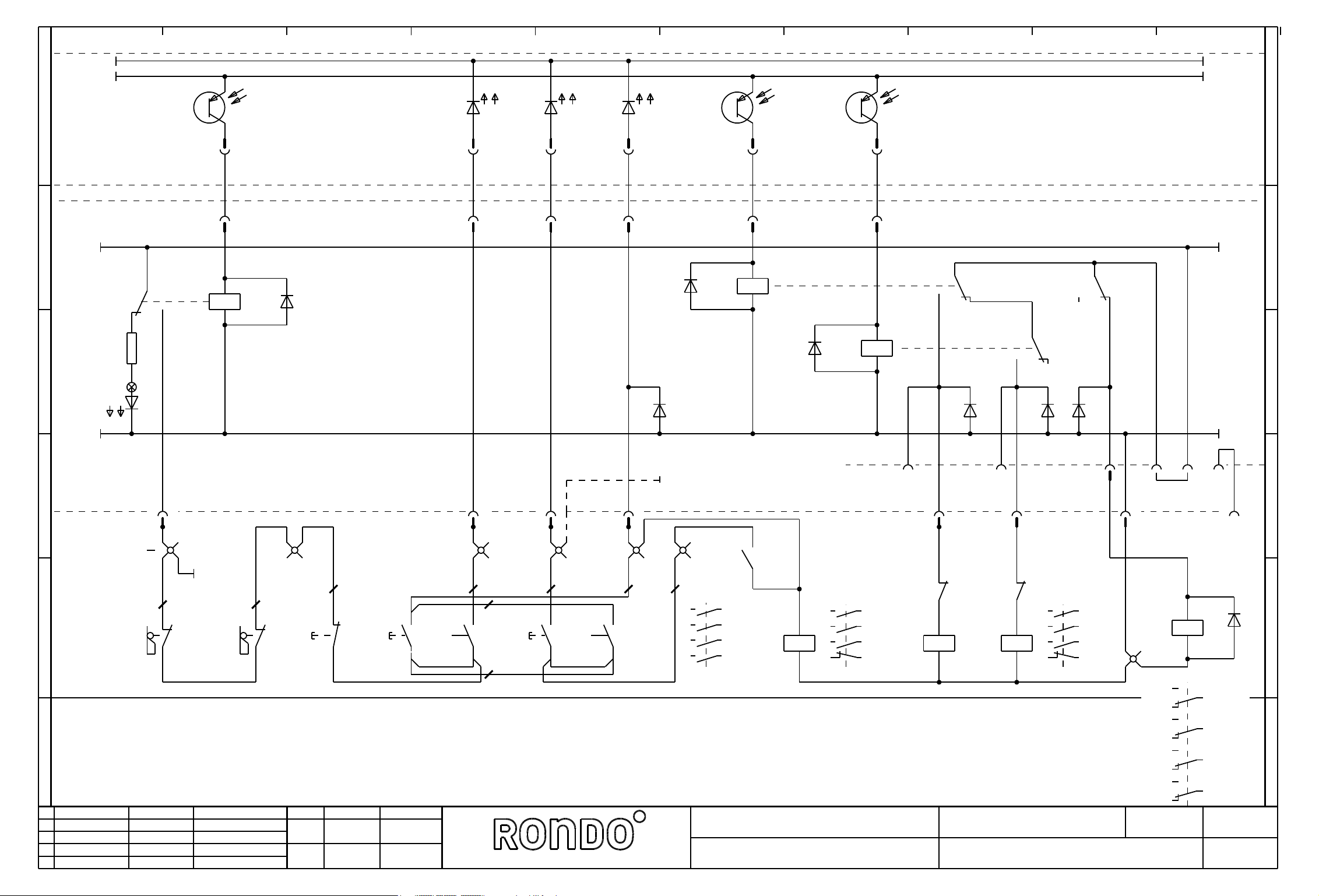
0
-24/2.9
+24-A/2.9
1
2 3 4 5 6 7
8
9
-24/4.0
+24-A/4.0
A
+24/2.9
B
C
GND/2.9
R3
H1
16
E3
+2
-X2
16
-X7
20
+2
-X2
204
D9
K9
-X7
3
A2
+2
-X2
3
-X7
12
A11
+2
-X2
12
A
+24/4.0
3
4
2
K13
3
4
2
B
E5 E7
+2
18
-X2
18
-X7
-X7
1
A0
+2
-X2
1
-X7
3
42
K8 D8
3
D10
D15
K10
D16
24
D17
C
D22
GND/4.0
D
E
31.03.2010
Plot-Datum:
Änderung
e
b
c
d
32357
32370
-X5
-X5
-X1.
W7
13
+3
-S10
14
Schutzgitter
Grille de protection
Safety guard
links
gauche
left
Datum
03.09.01
04.10.2002
1
1
1
P1-2/4.0
1
Name
Spahr
Sa
+3
-S11
-X1
2
13
14
-S3
rechts
droite
right
2
W8
+2
gez.
gepr.
3
11
-S1
12
AUS
DECL.
OFF
Datum
11.09.97
-X1
2
2
3
4
-X1
3
1
3
4
2
+2
24
+2
-S1
.3 .3 .4 .4
13
14
13
+2
-S2
24
13
+2
-S2
1
W8.1
Start Maschine
Mise en marche machine
Start machine
Teig nach rechts
Pâte à droite
Dough to the righte
Name
Ryser
Teig nach links
Pâte à gauche
Dough to the left
Dough-how & more.
-X1
14
13
4
5
-X1
5
-X6
P1-3/4.2
6
13
-K1M
14
2
1
3 4
5 6
13 14
.6
2
/1.3
/1.3
/1.3
.5
-K1M
A1
A2
1
3 4
5 6
21
2
22
/1.1
/1.1
/1.1
.7
Hauptschütz für
Contacteur principal pour
Main contactor for
Netzeinspeisung EIN
Branchement au reseau ENCL.
Mains supply ON
Bez.
Anlagenbez.
Rondostar 3000 , SFS611
3
-K3M
.7
-K2M
4
5
5
21
6
6
22
-K2M
22
A1
-K3M
A2
.7
21
A1
A2
1
3 4
5 6
21
2
22
/1.3
/1.3
/1.3
.7
Hauptantrieb
Commande principale
Main drive
Zeichn.-Nr.:
500680e
Auftrag:
5
-X1
5
7
Ort:
7
-K4
10
1
14
12
24
22
34
32
44
42
127
A1
A2
11
21
31
41
Anlage:
Bl:
/4.9
D
8
E
RONST01
3
Bl.
Page 97

0
-24/3.9
+24-A/3.9
1
2 3 4 5 6 7
8
9
A
B
C
+24/3.9
GND/3.9
-X7
19
E6
+2
-X2
19
X81
X82
-X7
-X6
17
E4
+2
-X2
17
6
-X7
K14
5
A4
+2
-X2
5
D18
-X7
K13
6
A5
+2
-X2
6
D21
-X7
K11
2
A1
+2
-X2
2
D20
-X7
K12
4
A3
+2
-X2
4
D19
K12
A
K14
-D13
5 7
K11
6
5
7
6
4 2
3
3
2
4 2
4
B
3
D23
C
L17/1.9
D
L18/1.9
E
P1-2/3.1
31.03.2010
Plot-Datum:
Änderung
e
b
c
d
34009
32370
-X5
-X5
9
3
4
Freigabe Überführen
Transfertisch
Tapis de transfer
Transfer conveyor
Datum
19.10.04
04.10.2002
Name
Blaser
Sa
9
20
Als Option
Comme option
As option
EU
21
P1-3/3.4
P1-2/3.1
Reserve Reserve
gez.
gepr.
Datum
11.09.97
Name
Ryser
-X10
4
3
-X10
W6
Als Option
Comme option
As option
UL
4
21
Teighaspel
Enrouleur à pâte
Dough reeler
schliessen = 1
ferme = 1
close =1
Dough-how & more.
Teighaspel
Enrouleur à pâte
Dough reeler
EIN / AUS
ENCL. / DECL.
ON / OFF
Bez.
Anlagenbez.
Rondostar 3000 , SFS611
Teighaspel
Enrouleur à pâte
Dough reeler
+3
-X10S
L=linke Kupplung
R=rechte Kupplung
2
2
2
24 VDC
3
1,6 A
200 N
braun
-X10
-X10
+3
-G1
M
Teig nach rechts
Teig nach links
Zeichn.-Nr.:
Auftrag:
1
-X10
-X10
1
1
4
blau
W15
500680e
4
-X10
-X10
4
grau
32
2
3
L
RRL
+3
-Y3
3
3
orange
braun
4
L
L
1
2
Ort:
31
21
-Y2
1
-K4
/3.9
2224
violett
1
R
R
1
+3
2
Anlage:
RONST01
Bl:
D
E
30
4
Bl.
Page 98

A
0
1
2 3 4 5 6 7
Grundmodul
Module de base
Basic module
-A1
Handrad
Bouton tourant
Turning knob
+2
-G1
Absolutwertgeber
Codeur en valeur absolue
Rotary Encoder
+3
-G2
-
+
GND
Sig.
+3
-B1
+3
-B2
8
9
Empfängerkopf
Tête de récepteur
B1
Receiver head
Senderkopf
Tête de transmetteur
Transmitter head
B2
Lichtschranke
Relais photoelectrique
Light barrier
A
B
C
D
-W12
weiss
braun
-W13
-W14
rot
58
59
60
61
123
W11
4
4
B
C
D
E
31.03.2010
Plot-Datum:
Änderung
e
b
c
d
Datum
Name
gez.
gepr.
Prozessoreinheit mit display
Unite microprocesseur avec display
Microprocessor unit with display
Datum
22.03.2002
Name
Ryser
Dough-how & more.
Bez.
Anlagenbez.
Rondostar 3000 , SFS611
Zeichn.-Nr.:
500680e
Auftrag:
Ort:
1
Anlage:
RONST01
Bl:
5
E
Bl.
Page 99

0
1
2 3 4 5 6 7
RONDO Burgdorf AG
8
9
A
B
C
Heimiswilstrasse 42
CH-3400 Burgdorf
Tel.:
Fax:
Webseite:
E-mail:
+41 (0)34 420 81 11
+41 (0)34 420 81 99
www.rondo-online.com
service a ch.rondo-online.com
Rondostar 3000 Cutomat SFS611C
A
B
C
D
E
31.03.2010
Plot-Datum:
Änderung
a
b
c
d
32357
32363
32370
34010
Datum
03.09.01.
19.02.02
25.10.02
19.10.04
Name
Spahr
Blaser
Blaser
Blaser
gez.
gepr.
Datum
08.09.2009
Name
Trachsel
Dough-how & more.
Bez.
Anlagenbez.
Zeichn.-Nr.:
500681d
Auftrag:
Rondostar 3000 Cutomat SFS611C
Ort:
1
Anlage:
RONST02
Bl:
0.1
D
E
Bl.
Page 100

1
BENENNUNG DEUTSCH
POS
BENENNUNG FRANZOESISCH
BENENNUNG ENGLISCH
1 Grundmodul -A1 1.5 50477
Module de base +1 /
Module, basic =RONST02 Ecostar/Rondostar/Kombi
2 3 4 5 6 7
-BMK
+ORT
=ANLAGE
ARTIKEL-NR.
/
AUFTRAGS-NR.
TECHNISCHE DATEN 1
TECHNISCHE DATEN 2
BEMERKUNGEN
POS
17 Widerstand -R2 1.1 R1.5K Rn=1,5kOhm Pn=0,6W
Resistances +1 /
Resistor =RONST02
BENENNUNG DEUTSCH
BENENNUNG FRANZOESISCH
BENENNUNG ENGLISCH
-BMK
+ORT
=ANLAGE
8
BL.PFADBL.PFAD
ARTIKEL-NR.
/
AUFTRAGS-NR.
9
TECHNISCHE DATEN 1
TECHNISCHE DATEN 2
BEMERKUNGEN
10
2 Sicherung traeg -A1/F1 1.6 50495 In=T 0,63A Dm=5x20
Fusible a act. ret. +1 /
Fuse slow =RONST02
3 Sicherung traeg -A1/F2 1.6 8935 In=T 2.0A Dm=5x20
Fusible a act. ret. +1 /
Fuse slow =RONST02
4 Sicherung traeg -A1/F3 1.6 8935 In=T 2.0A Dm=5x20
Fusible a act. ret. +1 /
Fuse slow =RONST02
5 Frequenzumrichte u. Parameter -G1 1.2 135202V1 1x200-230V; 50/60Hz; 1.5kW
Conv.de freq. et paramètre +1 /
Freq.converter and parameters =RONST02
6 Dreiphasen Frequenzumrichter -G1 1.2 50625 Un=230VAC 50/60Hz Pn=1,5kW
Convertisseur de frequence +1 / Ua=3x0-230VAC
Frequency converters =RONST02
7 | oder -G1 1.2 oder
|--------- ou--------| +1 /
or | =RONST02
8 Frequenzumrichte u. Parameter -G1 1.2 135203V1 1x380-460V; 50/60Hz; 1.5kW
Conv.de freq. et paramètre +1 /
Freq.converter and parameters =RONST02
9 Dreiphasen Frequenzumrichter -G1 1.2 50626 Un=400VAC 50/60Hz Pn=1,5kW
Convertisseur de frequence +1 / Ua=3x0-400VAC
Frequency converters =RONST02
18 Flachbandkabel -W12 6.3 50484 20 pol.
Cables plat +1 / lm=2100mm
Ribbon cable =RONST02
19 Kabel Empfaenger -W13 6.6 106111 2 pol mit Stecker
Cables recepteur +1 / lm=2200mm
Cable receiver =RONST02
20 Kabel Sender -W14 6.6 106112 2 pol mit Stecker
Cables transmetteur +1 / lm=1000mm
Cable transmitter =RONST02
21 ZF-Durchgangsklemme v. oben,4L -X1. 3.0 52120 4 x 2.5mm2
Borne +1 /
Terminal =RONST02
22 Abschlusswand 4L -X1. 3.0 52124
Plaque de fermeture +1 /
End cover plate =RONST02
23 ZF Schutzleiterklemme isol.;4L -X1. 3.0 52122 4 x 2,5mm2
Borne de terre +1 /
Earth terminal =RONST02
24 Endklammer für TS35 -X1. 3.0 52131
Piece finale +1 /
End piece =RONST02
25 Dreiphasen-Netzfiter -Z1 1.2 50628 Un=400VAC 50/60Hz
Filtre au reseau thriphase +1 / In=8 Amp.
Threephase mains filter =RONST02
10 Kleinleistungsschuetz -K1M 3.4 50361 Usp.=24VDC
Contacteur de petit calibre +1 /
Contactor miniature =RONST02
11 Hilfschalterbaustein -K1M 3.4 50359 2xS
Module de contacts auxiliaires +1 /
Contact component auxiliary =RONST02
12 Kleinleistungsschuetz -K2M 3.9 50362 Usp.=24VDC
Contacteur de petit calibre +1 /
Contactor miniature =RONST02
13 Hilfschalterbaustein -K2M 3.9 50359 2xS
Module de contacts auxiliaires +1 /
Contact component auxiliary =RONST02
14 Zeitrelais (abfallverzögert) -K3T 3.7 50604 Usp.=24-240 VAC/DC
Relais temporise +1 / t=
Time lag relay =RONST02
15 Klein Steckrelais -K4 5.1.9 50092 Usp.=24VDC
Petit relais enfichable +1 / 14 pol 4W
Plug-in relay miniature =RONST02
16 Stecksockel m. Loeschdiode -K4 5.1.9 50172 14 pol
Socle enfichable +1 /
Plug-in socket =RONST02
Plot-Datum:
a
b
c
d
31.03.2010
Änderung
Datum
Name
gez.
gepr.
Datum
08.11.2004
Name
Blaser
Dough-how & more.
26 | oder -Z1 1.2 oder
|--------- ou--------| +1 /
or | =RONST02
27 Dreiphasen-Netzfiter -Z1 1.2 50627 Un=240VAC 50/60Hz
Filtre au reseau thriphase +1 / In=6 Amp.
Threephase mains filter =RONST02
28 Prozessoreinheit -A2 1.5 50587
Unite microprocesseur +2 /
Microprocessor unit =RONST02 Rondostar
29 Handrad -G1 6.4 50481
Bouton tourant +2 /
Turning knob =RONST02
30 Drehknopf -G1 6.4 50483 d=65mm
Bouton tournant +2 /
Turning knob =RONST02
31 Impuls-Pilztaster schwarz -S1 3.5 50925
Bouton-poussoir noir +2 /
Push-button black =RONST02
32 Hilfsschalterblock 2S -S1 3.5 50927 2 x S
Element de contact +2 /
Contact element =RONST02
Gerätestückliste
Bez.
Anlagenbez.
Zeichn.-Nr.:
500681d
Auftrag:
Rondostar 3000 Cutomat SFS611C
Ort:
Anlage:
GERLIST
Bl:
1
Bl.
 Loading...