

Page 1

Technical Instructions 7004.N
16 Mar 2010 1
15 '''
Technical Specifications
ø Total 34.60 mm
ø Case fitting 33.80 mm
Movement height 5.60 mm
Height over battery 5.60 mm
Movement rest 0.60 mm
Height of stem 3.30 mm
Height of stem / travel 0.90 mm / 1 mm
Battery / Voltage Nr. 381 / 1.5V
Autonomy (theoretical) 48 months
Instantaneous rate (25°C) -10/+20 sec/month
Current cons. (typ.) 1.43µA (date mechanisme not in gear)
Current cons. (max.) 3.1µA
Torque sec. 10µNm (typ)
Torque minute 500µNm (typ)
Operating temperature 0°C - 50°C
Resist. to magn. fields 18.8 Oe = 1500 A/m
Resistance to shock NIHS 91 - 10
functions
Position I (crown) Neutral
Position II (crown) Setting the date (quick mode)
Position III (crown) Setting the time and retrograde day
Bigdate
Retro
Page 2
Technical Instructions 7004.N
Assembling
16 Mar 2010 2
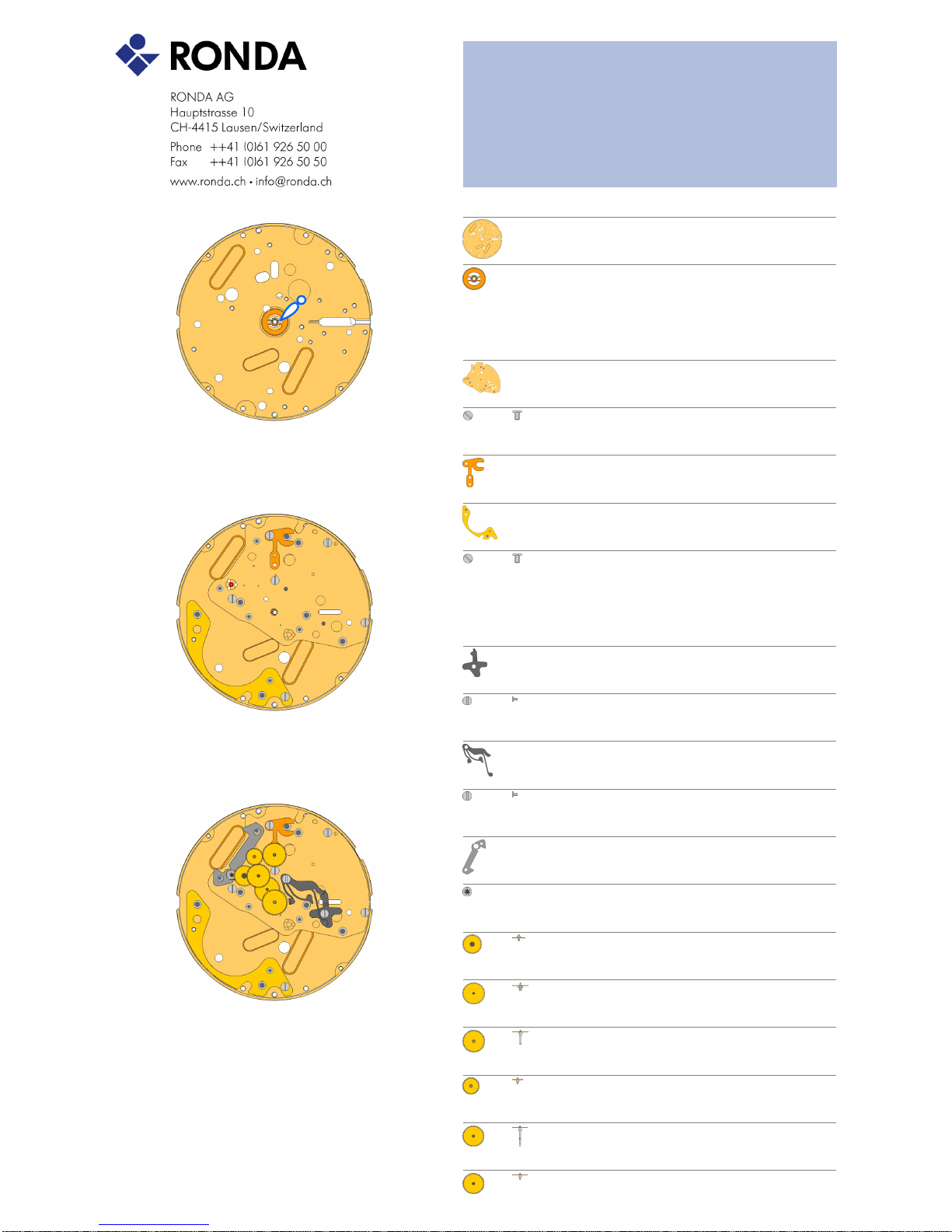
2000.669.G Main Plate1.
Use Moebius 9014 on bearing of all rubis
3305.329 Cannon pinion with driver B (Aig. 1)2.
Moebius 8200 greace must be placed between the steel tube and the
wheel. The steel tube must be placed into the center hole of the main
plate.
A
2030.028.CO Centre Bridge3.
Use 3 screws 4000.250.
4000.250 Screws4.
B
3406.039 Sliding attachement5.
Use 1 screw 4000.250.
2130.181 Combined maintaining plate6.
Use 1 screw 4000.250.
4000.250 Screw7.
3016.028 Lever for setting lever8.
"If the stem and the mechanism is already placed on the backside,
place the stem into the middle position. Then use 1 screw 4000.249 to
fix the lever for setting lever."
4000.249 Screw9.
3016.027 Stop lever10.
Position the Stop lever under the ?Lever for setting lever? and fix the
Stop lever by using 1 screw 4000.249. The reset arm of the Stop lever
must be placed according to the picture. Use Moebius 8200 at the
contact point of the 2 levers.
4000.249 Screw11.
3622.044 Stator12.
3715.105.RK Rotor13.
Use an antimagnetic tweezers to place the rotor.
3147.060.CO Intermediate wheel14.
3122.062.CO Third wheel15.
3136.174.CO Centre second wheel (Aig. 1)16.
3004.203.CO Seconde intermediate wheel17.
3136.182.CO Small second wheel axle18.
3136.173.CO Centre second wheel (Aig. 1)19.
C
Page 3
Technical Instructions 7004.N
Assembling
16 Mar 2010 3
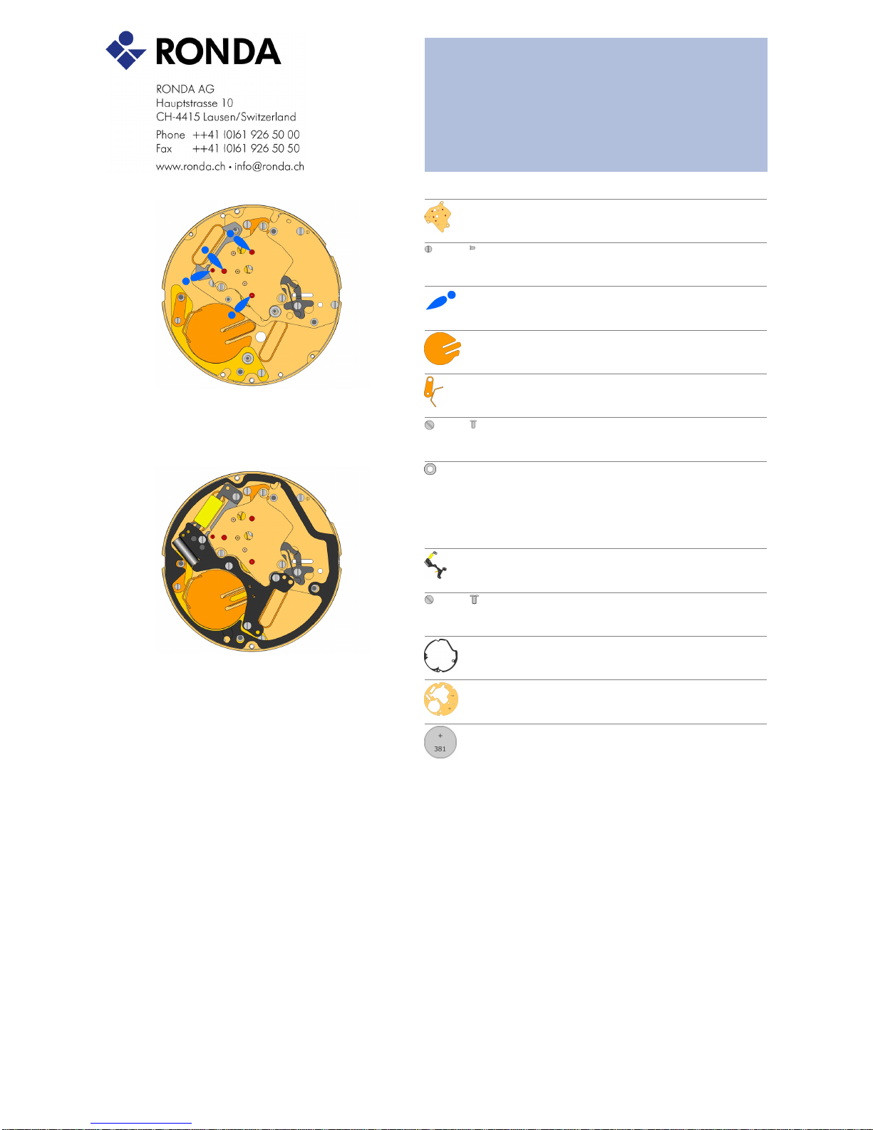
2020.170.FI Train wheel bridge 4 jewels20.
Attention: Prior to the fastening process of the bridge, all 4 pins of the
wheels must be visible in the 4 holes in the bridge. Use 3 screws
4000.250
4000.244 Screws21.
9014.000 Moebius 901422.
3603.080 Battery insulator23.
3601.120.G Battery clamp (+)24.
Use 1 screw 4000.248
4000.248 Screw25.
3503.071 Tube26.
2 pieces
D
3612.196 Electronic module (small second)27.
The coil is integrated into the electronic module. Use 5 screws
4000.250.
4000.250 Screws28.
3603.081 Spacer29.
2130.183.G Electronic module cover30.
Use 4 screws 4000.244
3600.032 Battery31.
Use a plastic tweezers to place the battery (to avoid short circuit of
battery).
E
Page 4
Technical Instructions 7004.N
Assembling
16 Mar 2010 4
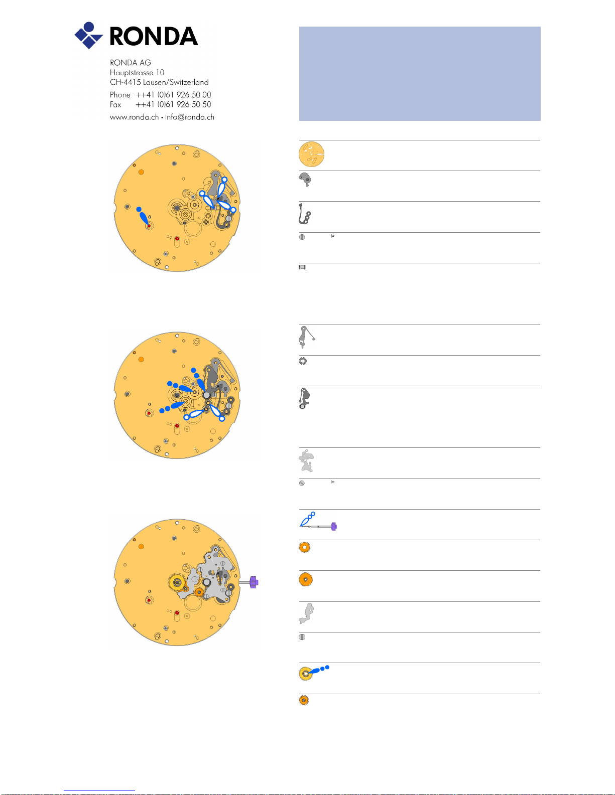
2000.669.G Main Plate32.
3017.054.CO Setting lever33.
3905.063 Setting lever jumper (3 positions)34.
The setting lever jumper must be tensioned and inserted into the
setting lever. Use one screw 4000.250. Use Moebius 8200 to grease
4000.282 Screw35.
3001.046 Sliding pinion36.
F
3015.077 Yoke (3 positions)37.
The yoke must be inserted into the cut out of the sliding pinion. Tense
the spring and connect in the main plate. Use Moebius 8200
3004.200 Corrector setting wheel38.
Use Moebius 8200 on both setting wheels.
3015.078.CO Rocking bar (3 positions)39.
Moebius 8200 greace must be placed between both levers. oiling
wheel with Moebius 9020.
G
2130.194 Setting mechanism cover40.
Use 4 screws 4000.305
4000.305 4 Screws41.
3000.194.CO Stem42.
Prior to the insertion of the stem, some greace must be placed on the
square part of the stem.
3004.204 Intermediate setting wheel43.
Use moebius 9020.
3007.079.CO Minute wheel44.
Use moebius 9020.
2130.185 Minute train bridge45.
Insert the minute train bridge in the main plate and fix it with 1 screw
4000.278.
4000.278 Screw46.
3301.296.CO Hour wheel (Aig. 1)47.
Use moebius 9020.
3147.066.CO Date corrector setting wheel48.
H
Page 5
Technical Instructions 7004.N
Assembling
16 Mar 2010 5
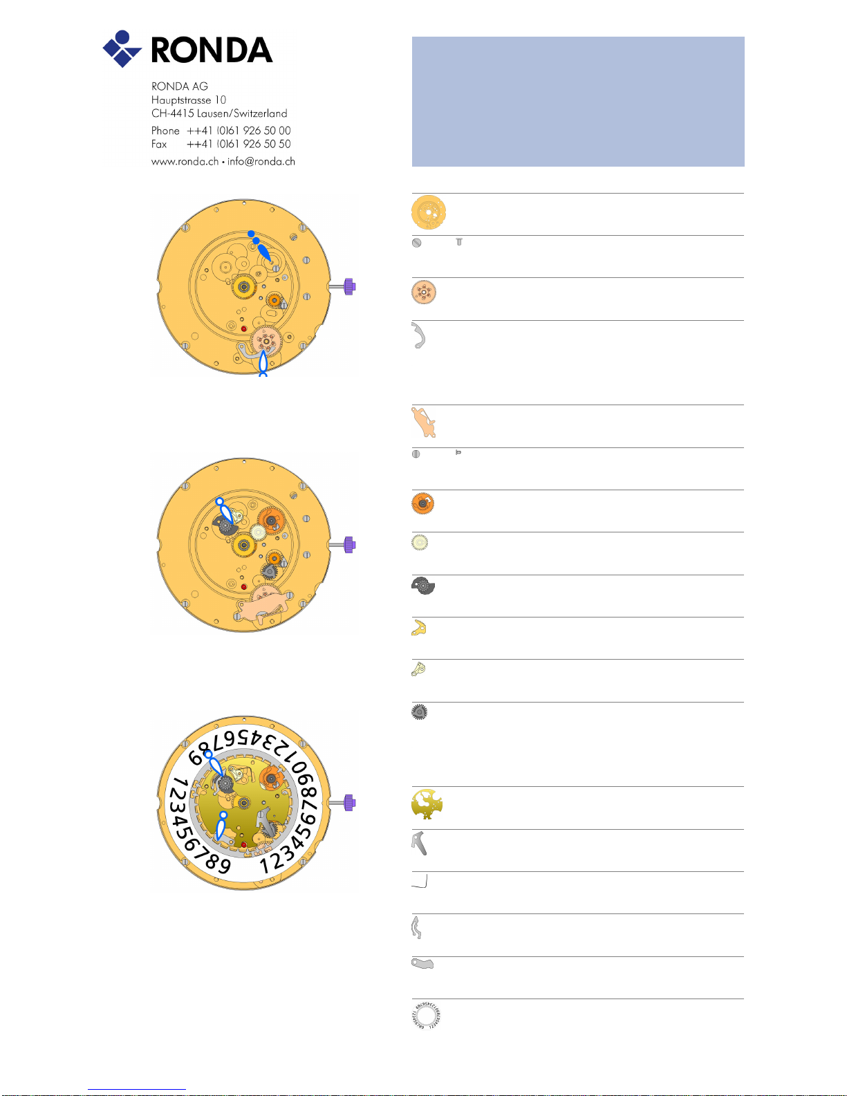
2000.672.G Main plate retro (12h)49.
Use 4 screws 4000.248
4000.248 Screw50.
3004.209 Tens indicator driving wheel51.
The short tooth of the tens indicator driving wheel must point to the
center of the movement.
3500.073 Tens jumper52.
Moebius 8200 greace must be placed between the tens jumper and the
tens indicator driving wheel.
I
2130.187 Tens jumper maintaining plate53.
Use 2 screws 4000.279. Place the spring loaded bracket outside of the
tens jumper.
4000.279 Screw54.
3004.208.CO Date indicator driving wheel55.
Oil must be placed at the pins before inserting the wheel.
3147.061 Intermediate date wheel56.
3404.006.CO Day cam (12h)57.
3406.032 Day rack58.
Moebius 8200 must be placed between cam and rack. Orientation of
the parts like indicated.
3406.031 Day rack lever59.
3507.059.CO Date corrector wheel60.
J
2130.191 Date indicator plate (12h)61.
3905.068 Date corrector spring62.
Use 1 screw 4000.244.
3905.066 Day rack lever spring63.
The Days rack lever spring must be tensioned and inserted as shown.
3500.069 Day jumper64.
Moebius 8200 greace must be placed between cam and day jumper.
3500.068 Date jumper65.
3504.234.AD Units indicator (T3/G6)66.
Teaths must be greaced using Moebius 8200. The 'half moon' cut out
on the unit indicator must point to the stem (position 3h).
K
Page 6

Technical Instructions 7004.N
Assembling
16 Mar 2010 6
2130.192 Date indicator maintaining plate67.
Use 1 screw 4000.250.
4000.250 Screw68.
3905.064 Date jumper spring69.
Insert the spring into the opening of the date indicator maintaining
plate.
3907.047 Day finger flange70.
"Turn the unit indicator forward by 30 days (quick mode). Then pull the
stem and adjust the time slowly until the date jump is executed ? after
the date jump stop turning the stem immediately! The ?half moon? cut
on the units indicator is now again pointing to the stem."
3004.211 Day finger71.
"Position the day finger as indicated and turn the day finger until it is in
contact with the day cam. By this method the time gab between change
of date and change of day indicator can be minimized."
L
3004.212 Days driving wheel72.
"Insert this wheel and assure, its bended down arm is properly inserted
into the counterpart on then Day finger. Make sure that during insertion
of this wheel, the Day finger is in contact with the day cam. This can be
done by slightly turning this wheel (counter clock wise) while inserting."
3401.082.FI Day indicator pinion73.
3147.062 Tens intermediate wheel74.
3315.003 Hour wheel friction spring75.
M
3504.231.AD Tens indicator (T3/G6)76.
The 'half moon' cut out on the tens indicator must point to the stem
(position 3h).
2130.193.G Date mecanism maintaining plate (12h)77.
Use 3 screws 4000.320.
4000.320 Screw78.
3506.077.G Dial support79.
3506.076.G Intermediate dial support80.
N
9010.000 Moebius 820081.
Microgliss D5 can be used
9014.000 Moebius 901482.
Use Moebius 9014 on bearing of all rubis
9018.000 Jismaa 12483.
Greace Moebius or Microgliss D5 an be used
9020.000 Moebius 902084.
Page 7
Technical Instructions 7004.N
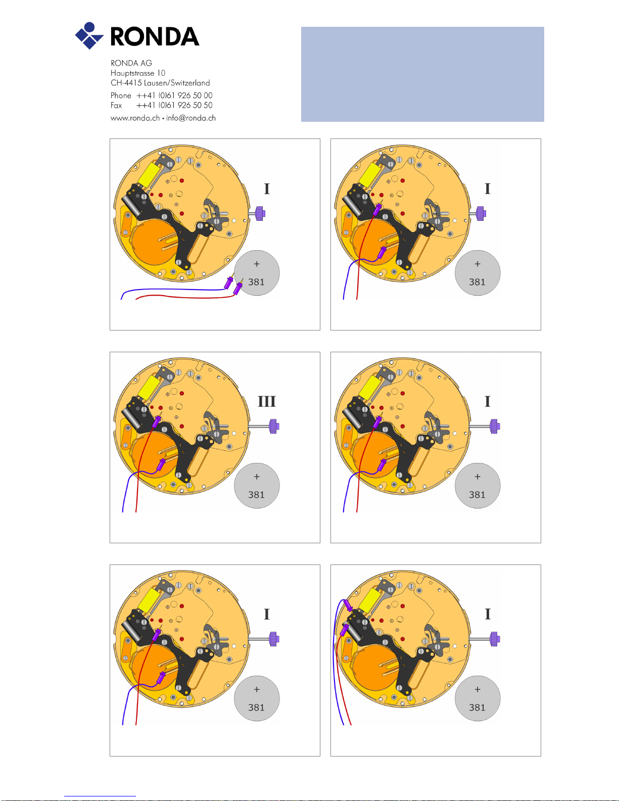
Electrical checking
16 Mar 2010 7
Voltage of battery
1.50 - 1.55 V
Battery test
Battery must be removed from movement
Consumption (M1) of movem. (Pos. I)
1.20 - 3.1 µA
Supply power from measurement equipment (1,55 V)
Consumption (M1) of movem. (Pos. III)
0.1 - 0.3 µA
Supply power from measurement equipment (1,55 V)
Lowest voltage for movement (M1)
less than 1.3V
Lower limit for operation of movement
Adjust voltage on the measuring eqipement to 1.55 V. The slowly reduce the
tension untill the movement stops
Accuracy (seconds / month)
-10/+20 s/M
Check for a time of minimal 60 seconds
Resistance of the coil: motor 1 (movem.)
1.5 - 1.7 kOhm
Ref. 3621.053.RK
The resistance of the coil can be measured on the electronics.
Page 8
Technical Instructions 7004.N
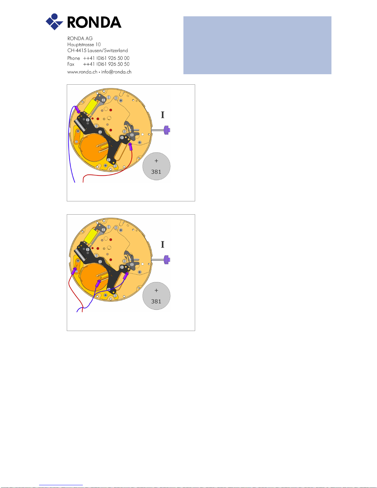
Electrical checking
16 Mar 2010 8
Coil insulation: motor 1 (M1)
... kOhm
indefinite high
The resistance between each coil and +pole must be measured.
Accelerated test of movement (M1)
1.55 V
8 steps / sec.
To activate this test mode, the corresponding test point must be connected to the
-Pole
 Loading...