

Page 1
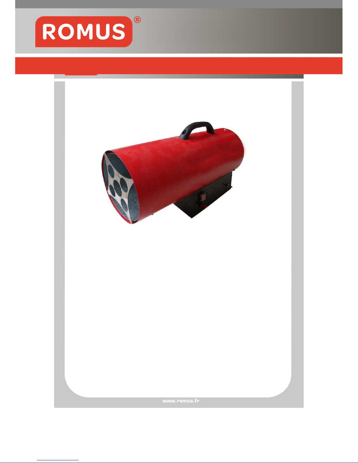
Direct fired air heater
Dear customer: thank you very much for choosing our products, it’s our
pleasure to offer you our products and service. Please read the user
manual carefully before using the appliance and operate following the
operation instructions in this manual, in order to prevent fire or other
accidental danger. Keep this manual in a safe place for future reference.
Any understanding problem relates to this manual please contact your
dealer.
HEATER « K-30 » Réf 93451
User’s Manual - GB
Page 2

Page 1
Warning
:
During operation always provide adequate ventilation and keep a 3.5
m safety distance away from combustible articles.
Page 3

Page 2
Contents
Safety warnings 3
Brief introduction of products 5
Overview of appliance 5
Dimensions 6
Technical data 6
Operation instructions 7
Gas supply circuit 9
Electric circuit 10
Exploded parts drawing 11
Parts name 12
Requires a hose and regulator 13
Maintenance of the appliance 13
Warning of local regulations 13
Trouble shooting 14
Page 4

Page 3
Safety warnings
For your own and other’s safety please read this USER’S MANUAL and follow its
instructions carefully.
△ Danger
1. Never use the heater where flammable vapors may be present, there is danger of
explosion, fire and burning。
2. Always provide adequate ventilation during the use. Only use the appliance in well
ventilated area, the air must be regular exchanged during the use (two times/one
hour), inadequate burning caused by oxygen shortage can cause carbon
monoxide poisoning.
3. Minimum ventilation requirements: When the appliance is used in inner room,
make sure the room space is no less than 330 m³ and the average air-circulation
opening area is no less than 825cm²
4. When gas leakage happens, firstly cut off the gas supply resource, then open all
ventilation equipments, use more fan to dilute the leak out gas, (attention:do not
use equipment which can cause sparkles when the leakage gas was not adequate
diluted.)
5. Do not put the machine in basement or use it under ground level, to avoid danger.
△ Warning
1. The appliance shall not be directed towards the gas cylinder
2. Don’t use spay products at the location where the heater is used,the gas from the
spay tin can cause danger of fire and explosion.
3. Don’t use the appliance in place with combustible powder(wastepaper, wood
crumbs, fibre scraps),if these powder are sucked in the heater and heated up,
flake and spark may be ejected out and cause fire and burning danger.
4. Never block air inlet or heating part,it can cause abnormal burning and fire.
5. Never modify the heater, alteration may cause malfunction and fire, is very
dangerous
6. This appliance is only for heating use in public area, should not be used for
household heating.
△ Attention
1. In order to prevent fire while in operation, please don’t place articles near the
heater. Keep all combustible materials away from heater. Minimum clearances:
Outlet (front) 3.5M,air inlet (rear) 2M,top 2M,side 2M.
2. While in operation,make sure that the ground surface does not
overheat,overheating may cause fire.
3. Do not fill fuel tank while heater is in operation, make sure the heater stopped and
the flame extinguished before you fill the tank. Filling while in operation may result
Page 5

Page 4
causing fire.
4. Before use the appliance, make sure that the voltage and frequency on site is in
accordance with the ones shown on rating plate
5. Not to be used for the heating of habitable areas of domestic premises; for use in
public buildings, refer to national regulations
6. Don’t expose the appliance to rain or snow, never use it in humidity places either.
Pull out the plug before the routine maintenance and examination.
△ Cleaning and maintenance
1. Keep the unit clean and remove the dust. Clean the unit at least once a
year. Use damp cloth to clean if it’s too dirty.
2. Let the appliance checked by customer service centre once a year.
3. Keep the appliance far away from inflammable objects.
4. When the appliance will not be in use for a long time, please remove the
plug from the outlet and gas supply pipe from the appliance,then put a
protection cover on the inlet pipe connection and place the appliance in a
dustproof bag, then put it in a cool and dry ort out of the reach of child.
Before you put the appliance in use again, make sure the fan works well
and no inflammable material is attached to the unit.
5. The need for isolating the appliance from the cylinder by means of the
cylinder isolating valve when not in operation
Warning: do not disassemble the appliance unless authorized by the supplier; do
not clean or repair the unit when it’s hot, or still in use, or the flexible
pipe is not removed, or the plug is not pulled out from the socket yet.
Danger of scalding or electric shock!
Page 6
Page 5
Brief introduction of products
1, This heater is a direct fired air heater, it incorporates a fan motor to increase
air circulation and enhance the oxygen supply to ensure the LPG gas burning.
It warms up the room as a space heater. By adopting the method of direct fired
air heating, it can achieve high heat input while keeps the energy consumption.
2, This product incorporates a multifunctional electromagnetic control device
which enables power shutoff-, flame failure- and overheating protections. The
three kinds of protections prevent the LPG gas leakage and potential carbon
monoxide poisoning and fire danger induced by LPG gas leakage.
3, The LPG gas rate adjustment valve is installed in this product, so the heat
input can be regulated to fulfill variable requirements at different locations.
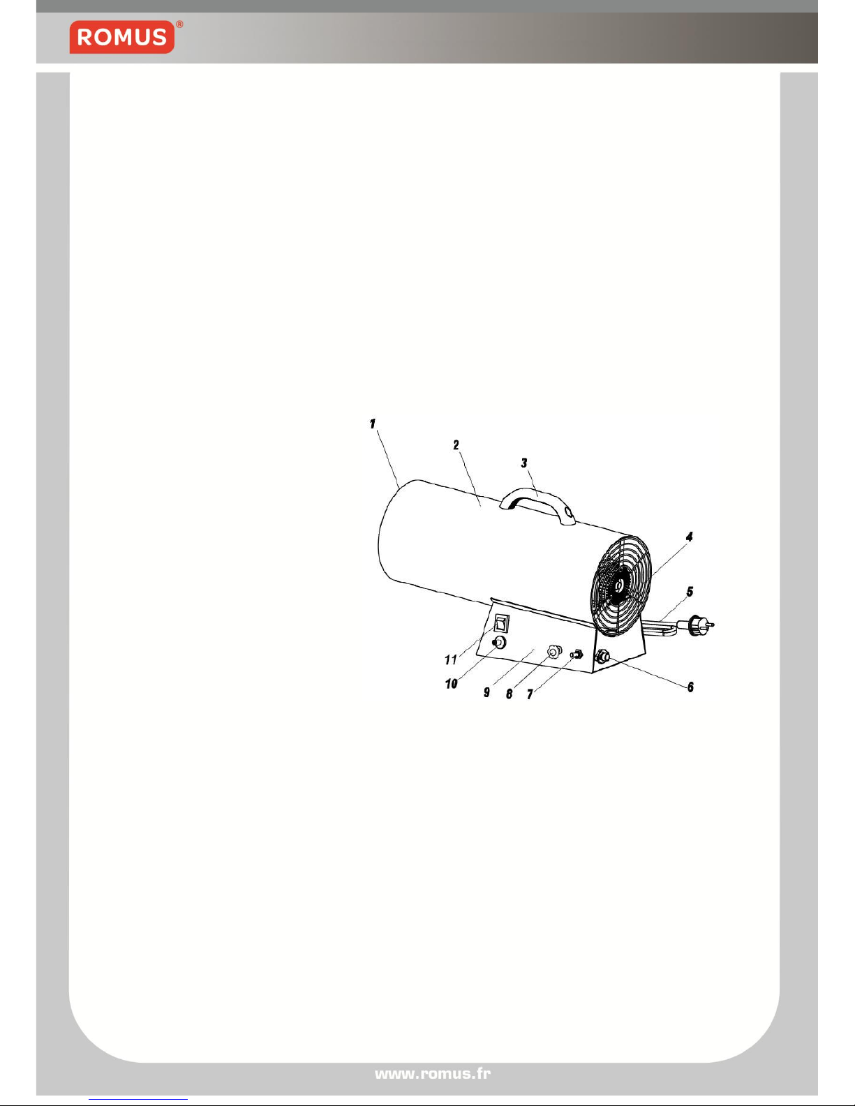
Overview of appliance
1. air outlet grid
2. housing
3. plastic handle
4. rear grid
5. power cord
6. gas inlet connector
7. flame supervision device
8. needle valve knob
9. control box
10. igniter
11. power switch
Page 7
Page 6
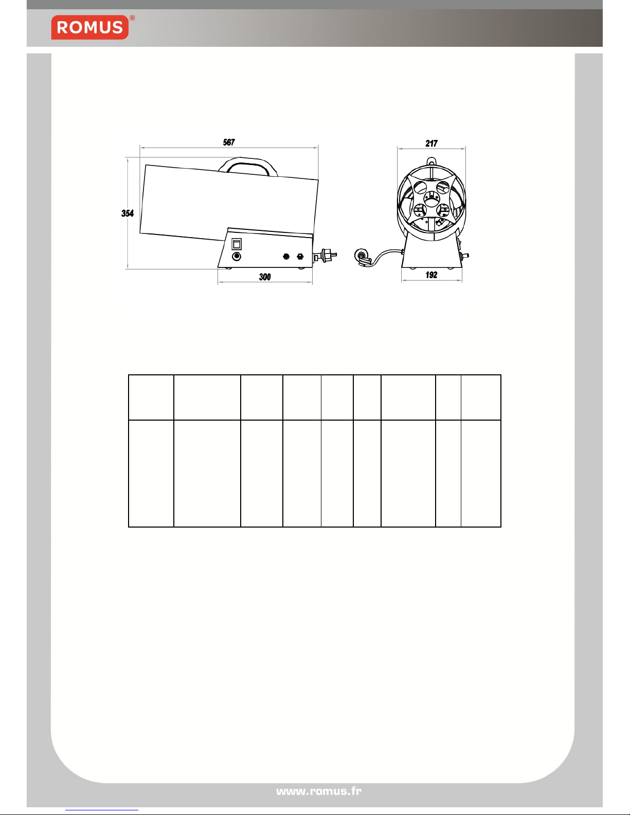
Dimensions
Technical data
Gas
category
Country of
destination
Degree of
electrical
protection
Gas
pressure
Rated
voltage
Motor
power
input
Max. gas
consumption
Max.
heat
input
Hot air
output
G30-I3B/P
AT,BE,DK,FI,
FR,DE,GR,IE,
IT,LT,NO,NL,
PL,PT,GB,ES,
SE,CH
IP44
1.5bar
220240V
50Hz
65W
2400g/h
33kw
1000m3/h
Page 8

Page 7
Operation instructions
1. Prepare a full cylinder gas according to the heating requirements.(The
gas container specification: no special requirements, the user can choose
a proper container according to heating requirements and the gas
consumption on marking label or consult the gas supplier.)
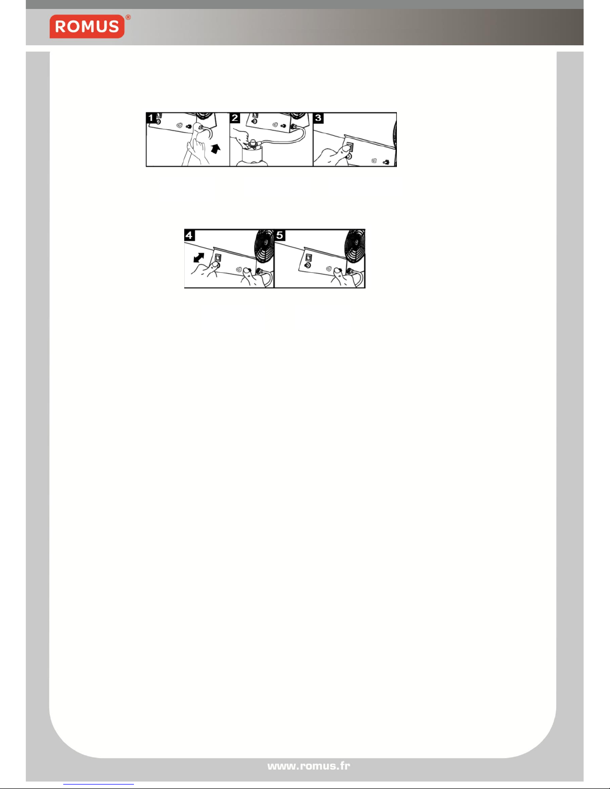
2. Put the heater on a stable working underground, take away the protection
guard from the machine, connect the other end of gas hose with machine
and tighten the locking connector nut to ensure the soundness of the gas
inlet.(Figure 1)
3. Connect one end (with pressure adjusting valve) of the gas hose to gas
cylinder, tighten the connector nut to make sure no gas leakage happens
and open the gas tap(Figure 2)
4. Set the regulator to the maximum setting.
5. Make sure the machine is proper connected with the gas cylinder and the
power switch is at the “OFF(O)” position, plug the power plug in the
socket outlet,shut on the power switch(put the power switch at the
“ON(1)”position.(Figure 3)
6. When the turning of the fan blades becomes stable, use the right hand to
push the aluminum handspike of the flameout protector and keep for 10
seconds, then use the left hand to press the igniter button for ignition.
(Figure 4)
7. After the gas ignites keep on pressing the handspike for another 10
seconds then release the right hand and the gas will burn
continuously.(Figure 5)
8. Turn the adjustment knob to regulate the flame length and make it comply
with the corresponding heat input.
Page 9
Page 8
9. repeat the above 2-8 steps when the machine runs out of gas and a new
full cylinder is to be replaced.(witch shall be undertaken in a flame-free
atmosphere)
Attention:
1. When you operate the machine according to the above procedures and the
heater doesn’t operate correctly after three times ignition, never try to ignite
again under this condition. There is explosion danger caused by high gas
concentration! Contact your dealer in time to clear the reason of
malfunction.
2. During the use try not to bend the flexible pipe to prevent the break of the
pipe and the danger of gas leakage.
3. Always equip the correct size of pressure adjusting valve and gas hose
when using the heaters (size of pressure adjusting valve: pressure
Pu=1.5bar±0.15bar. Flow volume Qn=8.0kg/h)
4. For the length of the flexible tube you may consult your gas supplier. A length with
1.5mis recommended,the type of the flexible pipe can be:10mm High Pressure
LPG Hose BS3212-Class 2/EN1763-1-Class 3-20Bar propane/butane or of higher
standards.
Figure 4
Figure 5
Figure 3
Figure 2
Figure 1
Page 10
Page 9
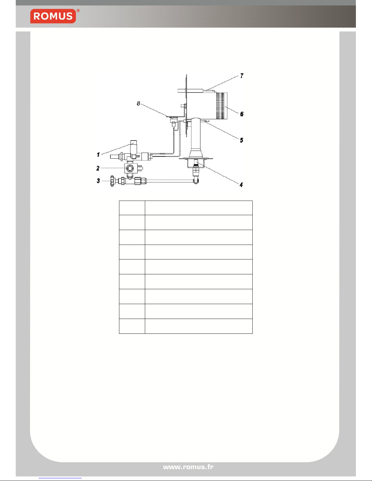
Gas supply circuit
Working principles
When the machine is connected to the gas supply, the gas passes in sequence
the following parts: 1. flame supervision device 2. automatic shut-off valve 3.
needle valve 4. Nozzle 5. being ignited by the high-voltage spark plug and
burning at the burning head. 6. Current occurs in the thermocouple due to the
heat output by gas burning. 7. The thermostat activates an electric circuit to
enable the small electromagnetic valve in the Flame supervision device
magnetizing the armature of flameout protection valve, the gas passes through
and burns continuously.
Item
Parts name
1
Flame supervision device
2
Automatic shut-off valve
3
Needle valve
4
Nozzle
5
Thermocouple
6
Burning head
7
Ignition needle
8
Thermostat
Page 11
Page 10
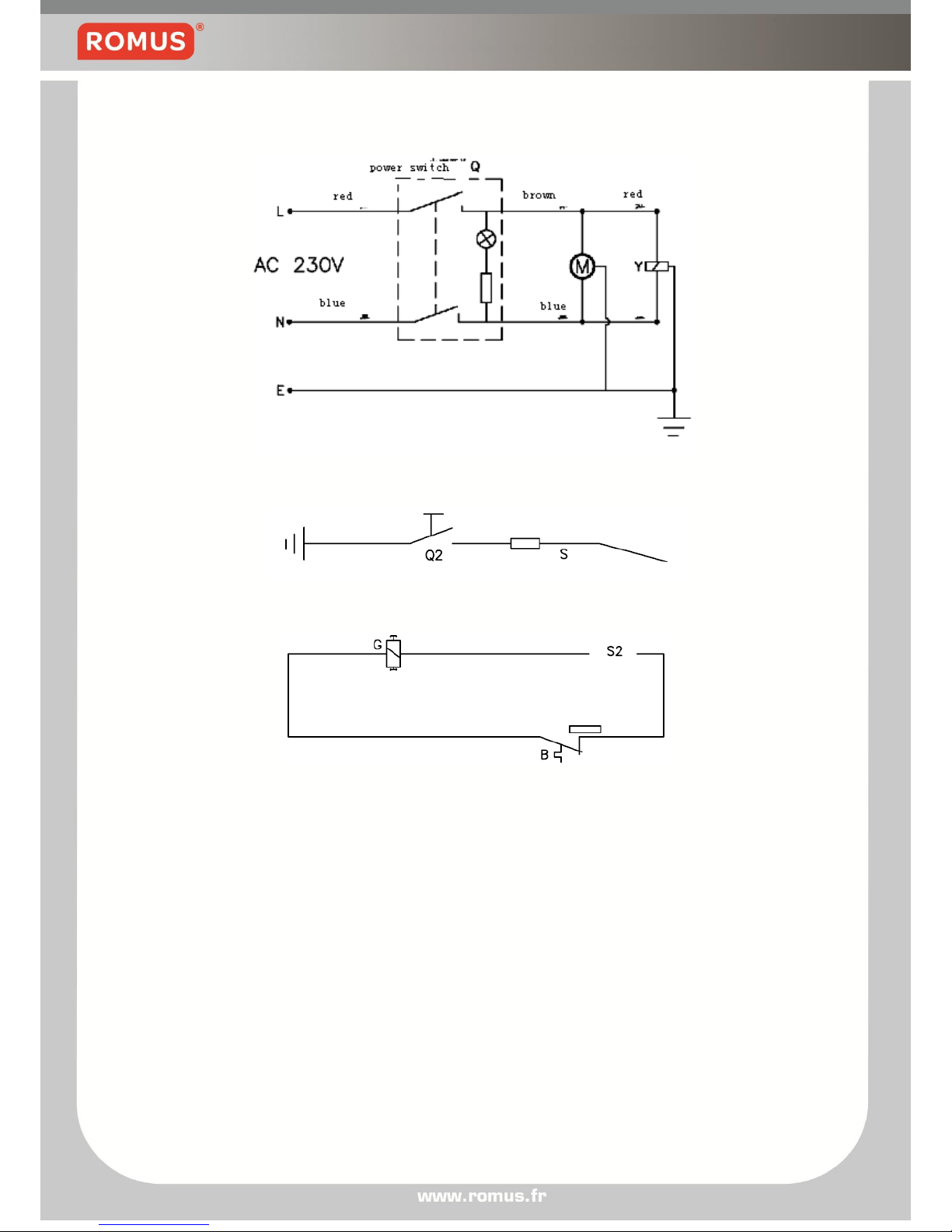
Electric circuit
Motor, electromagnetic valve circuit
Ignition circuit
Flameout protection circuit
B thermostat G integral electromagnetic valve in the flameout protector
M fan motor
Q power switch Q2 igniter S ignition needle
S2 thermocouple Y automatic shut-off valve C capacitor
Page 12
Page 11
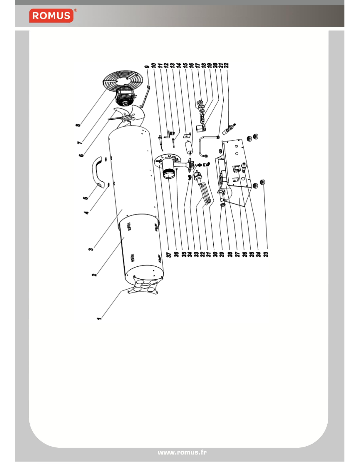
Exploded parts drawing
Page 13
Page 12
Parts name
Item name
1 Air outlet grid
2 Heat insulation barrel assembly
3 Housing
4 Nut of U shape
5 Plastic handle
6 Fan bladeφ200
7 Motor 65W AC220/240V 50-60Hz IP44
8 Rear grid
9 Motor supporter
10 Ignition needle
11 Thermostat supporter
12 Thermostat operation temperature 95℃
13 Thermocouple
14 Capacitor supporter
15 Capacitor 450V 2μF
16 Gas inlet connector
17 Gas inlet fixed nut
18 Fixation nut M12×P1.0
19 Flame supervision device
20 Automatic shut-off valve
21 Copper assembly
22 regulator
23 Mat
24 Ignition
25 Power switch
26 Control box
27 Burning head supporter
28 Coil supporter
29 Cord protection loop
30 nozzle seat
31 Line buckle
32 Power cord and plug
33 nozzle
34 Earthic terminal
35 Thermocouple clip
36 Burning head
37 Draught-block assembly
Page 14

Page 13
Requires a hose and regulator
1. In order to use more safety and to keep the machine well working. Please
follow below requirements to operate, make sure to buy the right redactor
and hose for this machine.
Regulator specification: enter press 2.5-16Bar / out press 1.5bar+0.15bar
Flux: 8.0Kg/h
2. The nut which in one end of the hose connected with machine specification
is G3/8L
Maintenance of the appliance
1. After the connections of flexible pipes and valves and before the use of the
appliance the user can check the soundness with liquid mixture of soap
and water. In case bubble happens, which indicates that there is leakage,
readjust the unit. Without bubbles, you may begin to use the unit.
2. The user shall choose the proper pressure-release valve according to the
working pressure indicated on the marking label
3. Examine the burning after the unit was ignited, the normal flame is blue
and it won’t get out of the front cover, the flame on the burn head is stable
and the full circle has equal shape. Not being like this, there is something
wrong with the burning.
4. When the appliance is used under unsafe circumstances, at least a professional
person shall be assigned to supervise the operation, to keep the appliance away
from inflammable objects at any time. And after the service wait until the appliance
cools down to ambient temperature before leaving. It’s strictly forbidden to use the
appliance in a place without adequate ventilation.
5. A list of spare parts available:no spare parts and attachments are
supplied when the appliance leaves factory, in case of need please enquiry
and purchase the parts from your gas supplier or your dealer
6. When the gas container insulation valve failed and the gas supply cannot
be shut off normally, first turn off the power switch, then pull out the plug,
send the unit together with the flexible pipe, gas container to gas supplier
for repair.(attention: do not lose the flexible pipe connection.)
Warning of local regulations
1、 For issues not mentioned in this manual please consult your gas supplier for
help. Use the appliance according to the local law requirements.
Page 15
Page 14
Trouble shooting
Problem
Reason
Solution
Motor don’t
work
1. Power switch damaged
1. replace the power switch
2. Motor damaged
2. replace the motor
Can’t ignite
1. Gas exhausted
1. replace the gas cylinder
2. Adjust the gap of ignition
2. adjust the gap between
ignition needle and the
burning head
3. Ignition needle damaged
3. replace the ignition
needle
4. Ignition damaged
4. replace the ignition
5. Automatic shut-off valve
damaged
5. replace the Automatic
shut-off valve
Flame failure
after a few
seconds of
ignite
1. the distance between the
thermocouple and burning
head is wrong
1.adjust the distance
2. Press the button of flame
supervision device too short
2. press the button of the
flame supervision device
retain 20 seconds
3. Thermocouple damaged
3.replace the thermocouple
damaged
Flame failure
after burning a
period of time
1. Gas exhausted
1. replace the gas cylinder
2. Interior overheat
2. increase air supply
 Loading...