

Romancell Technology Co., Ltd.
DUAL BAND
CELLPHONE SIGNAL BOOSTER
User Manual

Contents
Cell Booster Kit Package....................................................................................01
Cell Booster Connection Set Up
Pre-Installed Procedure
A. Outdoor ANT.......................................................................................................................02
B. Coaxial Cable......................................................................................................................02
C. Indoor ANT..........................................................................................................................03
D. Power Adaptor.....................................................................................................................03
E. Minimum Separation Distance Limitation.......................................................................03
F. LED Indication.....................................................................................................................04
...................................................................01
Detailed Installation Procedure
A. Outdoor ANT.......................................................................................................................05
B. Coaxial Cable......................................................................................................................06
C. Indoor ANT..........................................................................................................................07
D. Minimum Separation Distance Limitation.......................................................................07
E. LED Indication.....................................................................................................................08
Troubleshooting..........................................................................................................08
FAQ
Safeguard Features
.........................................................................................................................................10
..................................................................................................11
Safety Issue Remind & Notice........................................................................12
Default / Authorized Accessories List
Specifications
................................................................................................................14
.....................................................13

Cell Booster Kit Package
When the users get the cell booster DIY kit, please check the default content as the cell
booster kit package shown.
CELL BOOSTER
MAIN UNIT
CL06 -33FIFI
CL06 -17FIFI
RH-050120US
AC-DC ADAPTOR
SCREW&
WASHER
(8 pc s/ea)
PA- F 78OD
OUTDOOR ANTENNA
IA-CP2
INDOOR ANTENNA
AD-NEFO-06
RF ADAPTOR
N(M) -F(F)
33ft + 17ft (EXTENSION) RG 6/U
COAXIAL CABLE
Cell Booster Connection Set Up
Outdoor ANT
Coaxial Cable
RG 6/U
33ft or 33ft+17ft
AC ADAPTOR
AD-FOFO- 06
BRACKETU BOLT
Indoor ANT
RF ADAPTOR (SPARE)
F(F)-F(F)
Cell Booster Main Unit
1
Pre-installed Procedures
Before the cell booster installation, the users must read P.2-9 carefully for best
reception and preventing some unwnted ststus.
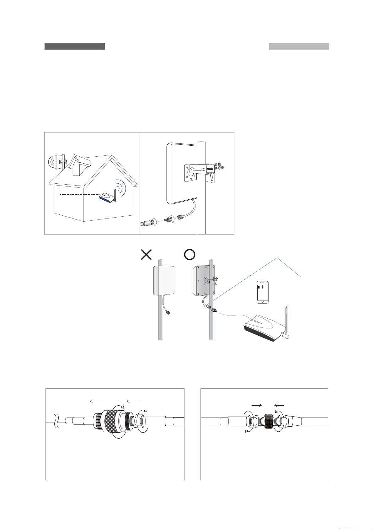
Outdoor ANT Installation
A
Outdoor ANT
Leave the outdoor ANT
slightly loose for best
reception tuning.
Indoor ANT
(Detailed procedures to
Cell Phone Repeater
find the best reception of
the outdoor ANT see P.4,5 )
CAUTION: Outdoor ANT
must not face toward
the house at any time
Coaxial Cable Installation
B
ODANT 33ft RG -6/U
Coaxial Cable
Outdoor ANT N connector + RF Adaptor
AD-N1F0-06 + RG-6/U F(M) connector
connected together tightly.
Long (33ft) RG-6/U coaxial extended
with short (17ft) RG-6/U (optional)
coaxial cable.
2
Indoor ANT Installation
C
※ Leave the main unit away from the window and remain more than 20ft (6m) direct
separation distance from the outdoor antenna to avoid the cell booster’s loop
oscillation.
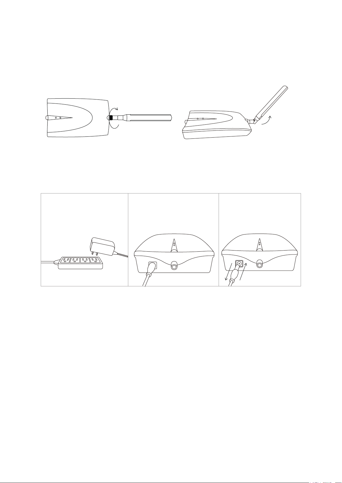
Power Adaptor
D
※ The cell booster power must be turned on after all the Outdoor/Indoor ANT has
been installed. Ensure that all the connectors are connected tightly for testing/using.
Plug the AC-DC Adaptor
in AC power.
Socket/Strip
※ Remove the DC plug from the DC jack of the cell booster, await 5 sec, re-plug to
Reset the power while re-adjust/tune the outdor antenna direction/location, or
debug the abnormal status each time.
Minimum Separation Distance Limitation
E
The minimum separation distance limitation (the distance between the outdoor ANT
and the booster) should be more than 20ft (6m) to avoid the cell booster that may
Power on the cell booster
►This action must be done
after all connection setup
has been completed!
Reset the power
1. 2.
cause loop oscillation.
※ The booster will shut down the circuit and cause the LED to blink. The users must
tune/adjust the outdoor ANT direction / location and / or lengthen the separation
distance between the outdoor ANT and booster for loop oscillation prevention.
(See P.5 for proper operation and P.9 for troubleshooting. For best reception, more
tuning/adjusting information see P.5 - P.6)
3
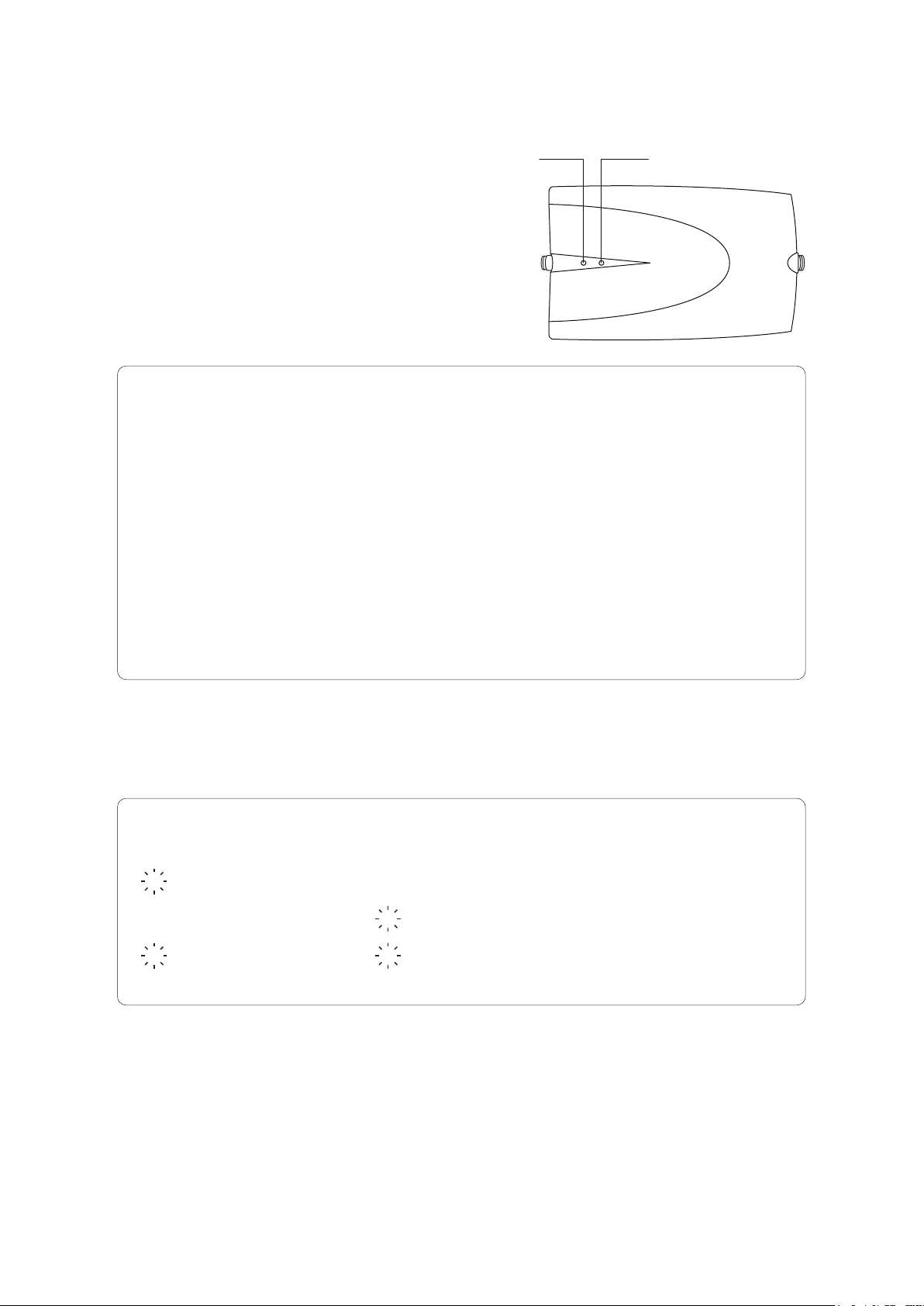
LED Indication
F
● Normal Status
Normal status is achieved when these 2 LED
800 Band 1900 Band
light indicates solid (Red and/or Green) non
blinking light:
800 Band
(Red)
○
(Red)
○
(Green)
○
(Green)
○
1900 Band
(Red)
○
(Green)
○
(Red)
○
(Green)
○
Basic reception, could be achieved better by tuning /
►
adjusting the outdoor ANT direction / location.
►
1900 band reception is good , 800 Band can be tuned /
adjusted for better reception.
►
800 band reception is good , 1900 Band can be tuned /
adjusted for better reception.
Both the 800 and 1900 Band are now in good reception.
►
LED indicator
● Abnormal Status
If any 1 or 2 LED blinking Red or Green must be avoided.
800 Band
(Blinking , Green or Red)
●
(Solid Red or Green)
○
(Blinking , Green or Red)
●
※ The users must turn off the power of cell booster , tune / adjust the outdoor ANT direction/location
and / or the separation distance between the outdoor ANT and cell booster. Reset the power of cell
booster again. Repeat this procedure and reset the power each tuning/adjusting cycle until the LED
Indicates the normal status (solid Red or Green).
※ The users must use the optional short extension cable (17ft) for direct separation distance extension
if the original long coaxial cable (33ft) causes any abnormal status.
1900 Band
(Solid Red or Green)
○
(Blinking , Green or Red)
●
(Blinking , Green or Red)
●
4

Detailed Installation Guide
Outdoor ANT Installation
A
Installation Procedures:
Toward the tower
The users may use 1 or 2 brackets for
fastening the mast in most installation.
Up-tilt the outdoor antenna in the valley for
best reception, and down-tilt the outdoor
antenna in higher altitude location.
● Procedure locating Best Reception of the Outdoor ANT
a. Best Way:
The users may use a smart cell phone in the test mode and read the dBm (it will be always
negative value and closer to 0dBm is stronger) to find the best reception:
1. One person turn the Outdoor ANT (roof ANT) outside in any direction, stand behind the
outdoor ANT (avoid blocking the reception), wait 30secs (for the smart phone to update its
reception status), the person inside the house (stand in a fixed position and hold the cell
phone in the same direction during the procedure of finding the best reception). Record the
reception power level in dBm
2. The person outside must tune the outdoor ANT 15° away from the original direction per step
and await 30 secs per tuning, let the person inside the house record the dBm value.
3. Repeat step 2 per tuning direction in 15° separated from the left to the right direction and
record the dBm value of each tuning direction.
4. Find the direction of the highest dBm reading and fasten the outdoor ANT. Use a tape to seal
the coaxial cable, RF Adaptor and the outdoor ANT’s connector for waterproof. (see P.6)
※ Reference dBm reading versus communication quality:
2G MODE
-78dBm ~ -40dBm
-85dBm ~ -79dBm
-92dBm ~ -86dBm
-99dBm ~ -93dBm
-110dBm ~ -10 0dBm
3G/4G MODE
-90dBm ~ -60dBm
-100dBm ~ -90dBm
-110dBm ~ -10 0dBm
-120dBm ~ -110dBm
-120dBm or less
Excellent reception
Good reception
Fair reception
Usable, fluctuation, smaller indoor service area
Poor, hard to make a phone call or reception
5

b. Additional Way:
The users may use the bar indicators of the cell phone to find the best reception:
It is entirely the same procedure as the step 1,2,3,4 of “Best way” to find the direction of best
reception as represented above . Choose the indicator with the most amount of bars for the best
reception and fasten the outdoor ANT with sealing tape for water proofing. (see P.5)
※ Bar Reception versus communication quality:
Excellent reception
Good reception
Usable, fluctuation, smaller indoor service area
Usable, fluctuation, very small indoor service area
Poor, hard to make a phone call or reception
B
Coaxial Cable Installation
The connection of the outdoor ANT with RF adaptor AD-N1F0-06 and the F(M)
connector of the RG-6/U coaxial cable must be sealed by the sealant tape to prevent
corrosion by rain water or melting snow.
WINDING DIRECTION
STA RT H ERE
Stop here, wind in the reverse
over the first layer of the
sealant tape.
The users may use the long coaxial cable 33ft (10m) for installation, the 17ft (5m)
coaxial cable is an extension cable for longer cable path application (optional).
WINDING BACK
Wind back over the second layer of the
sealant tape.
※ Make a U shape path when the coaxial cable enters into the house to prevent the
rain water from dropping along with the coaxial cable.
※ Do not allow the coaxial cable to curl upon entry, it may cause instability and the
booster loop oscillation.
6

C Indoor Antenna
RECOMMENDED NOT RECOMMENDED
※ Remain 135° from the cell booster for better service coverage and system stability.
※ Leave the mainunit away from the window and remain more than 20ft (6m) direct
seperation distance from the outdoor antenna to avoid the cell booster’s loop
oscillation.
Minimum Separation Distance Limitation
D
● Allow more than 20ft (6m) direct separation distance between the outdoor ANT and
cell booster to avoid the loop oscillation to cause the booster to shut down with any
1 or 2 blinking LED.
● The users must remove the DC plug from the DC jack of the cell booster
immediately and tune/adjust the outdoor ANT direction/location. You may need to
lengthen the direct distance between the outdoor ANT and cell booster. Re-plug the
DC plug to the DC Jack of the booster as reset , verify these 2 LED lit solid red
and/or green.
● Verify that the 2 LED lights are lit (red or green), not blinking (LED solid lit is a must
requirement for this booster in normal operation).
● If it is still blinking in any 1 or 2 LED , the users must remove the DC plug from the
DC jack of the cell booster, repeat tuning/adjusting the ODANT for each cycle, then,
reset the DC power of the cell booster until the 2 LED lights indicate solid red
and/or green.
● The users may further tune/adjust the direction/location to find the best reception.
(see P.4)
7

LED Indication
E
● At any condition, the 2 LED lit remains solid Red or Green which represents the
cell booster in normal operation.
Solid R LED: The outdoor ANT captures insufficient outdoor cell tower signal level,
smaller indoor service area. If far away for cell tower, it could be solid red only.
Solid G LED: Sufficient outdoor cell tower signal level was captured by the outdoor ANT,
larger indoor service area improving the service quality both voice and mobile internet.
● If any 1 or 2 LED lights are still blinking , either red or green must be avoided:
R LED blinking: Loop oscillation shuts down the cell booster and no longer enhance the
reception, the troubleshooting procedure see P.9.
G LED blinking: The outdoor ANT captures excessive signal level, and shuts down the
cell booster. Generally, indicates the house is near the cell tower. The users must
tune/adjust the outdoor antenna direction/location away from the cell tower to prevent the
excessive reception. (See Abnormal operation of troubleshooting, P.10)
and 3rd Q&A of frequently asked questions, P.11)
※ To tune / adjust the outdoor ANT direction / location to allow the 2 green lights to
become solid which allows the best reception both voice and mobile Internet and larger
indoor coverage. (Detailed tuning procedure see P.5)
※ In fringe area, the cell booster may still be 1 or 2 solid RED LED even after after
carefully tuning/adjusting the outdoor ANT, that is the users allocation is far away from the
cell tower for the RED LED band.
Anyway, operationl status in solid RED LED, the users must still tune/adjust the
outdoor ANT direction/location to get a better reception. (Better service quality
and larger indoor service coverage in the fringe area.) (see P.5)
Troubleshooting
The users may verify the color of these 2 LED of the cell booster as an indication of
the operational status. Users should follow the LED indication to solve the problem.
Normal operation: These 2 LED lit solid Red or Green, non blinking:
● 2 LED in solid RED but poor reception:
Tune / Adjust the outdoor ANT direction / location as shown in P.5 to increase the incoming
cell signal level which may improve both voice and mobile internet service coverage and
quality.
8

※ If the location of the residential house in fringe area like far away from cell tower or
mountain area, valley, it may cause poor reception after carefully tuning / adjusting the
outdoor ANT.
● 2 LED in solid Red but no reception:
Check all the connection are well connected as below:
a. Outdoor ANT + RF Adaptor + RG-6/U coaxial connector
b. RG-6/U coaxial connector + outdoor ANT connector of cell booster Indoor ANT
c. Connectors cell booster + Indoor whip ANT
d. RG-6/U coaxial connector + RF Adaptor + RG-6/U coaxial connector if the 17ft
optional extension cable connection is used.
※ The users should power off and on again (Reset the power, P.3) the cell booster to
ensure whether the new status is fine after any improvement procedure.
Abnormal operation: Any 1 or 2 LED blinking either Red or Green
● Blinking 1 or 2 RED LED: It is loop oscillation shut down. The users must turn off
the DC power of the cell booster. Tune/adjust the outdoor ANT direction/location
and / or extend the separation distance between the outdoor ANT and cell booster.
Reset the DC power of the cell booster until the LED is in normal operation status.
● Blinking Green LED indicates the outdoor ANT is facing toward proximity of the cell
tower which captures excessive signal level. The users need to tune / adjust the
direction / location of the outdoor ANT away from proximity of the cell tower and use
the wall blockage of the residential house to reduce the excessive cell signal level of
the proximity of cell tower and reset the cell booster.
2 LED non lit:
● To verify the 110VAC power socket / strip first.
● If the AC power socket / strip is normally working, check the AC-DC Adaptor
connection both AC or DC plug to ensure the power deliver to the cell booster.
● If the AC-DC Adaptor cannot deliver the DC power to the cell booster, consult your
dealer for a new AC-DC Adaptor.
9

Frequently Asked Questions
Q:
How will the weather affect to the cell phone indoor reception?
A:
Sunny or cloudy day will not affect the indoor reception. Rainy, snowy, foggy day
will reduce the indoor reception coverage, especially heavy rain, snow, fog may affect
more. Also, the rain, snow, fog has more influence on PCS Band for its higher
propagation loss than cellular band.
Q:
Why the loop oscillation is the most important issue for a cell booster
installation? How can I verify and prevent from it?
A:
The loop oscillation not only causes the cell booster to no longer serves the user’s
link and not enough distance separation between the outdoor ANT and booster.
The users may check the 2 LED on the booster as the status indication of loop
oscillation. Any 1 or 2 of the RED lit is blinking indicates loop oscillation of the cell
booster. Remove the DC-plug from the DC jack of booster immediately, and follow the
improvement procedure shown in P.5 or 6 until these 2 LED lit either solid Red or Green.
Q:
If my house is nearby the other operator’s cell tower and my cell operator’s tower
is far from my house. How can I install and prevent the excessive signal level coming
from the nearby cell tower?
A:
First, you should turn away the outdoor ANT direction from the nearby cell tower
and choose another direction/location, also, by using the house wall as the blockage of
the nearby cell tower.
Q:
Can the cell booster serve multiple users simultaneously?
A:
Yes. The booster is designed for the multi-users operation for it is linear
amplification and controls the overall power as well as blocking the interference of the
cell tower.
Q:
Can the cell booster help Wi-Fi reception?
A:
No. It cannot help the home Wi-Fi reception for they are different frequency band
between the cell band and Wi-Fi band.
Q:
Does this cell booster help 4G700 and AWS band?
A:
No, the cell booster only helps 800 (cellular) and 1900 (PCS) band.
All the mobile operators in 800 and 1900 band may be increased the reception inside the
house by this booster.
Q:
Is the cell booster helpful or harmful for human health?
A: It is helpful for human health by installing the cell booster.
The cell booster makes the cell phone radiates lower RF power to cell tower than not
using a cell booster inside the house. The lower RF power radiated from the cell phone
is not only helpful for human health also extend the battery life span.
Q:
Why do we use a panel ANT instead of an omni-directional ANT?
The panel ANT is a directional ANT which captures more cell signals from tower
A:
than the omni-directional ANT. That makes the panel ANT offers better service quality
and larger indoor service area.
10

Safeguard Features
Anti – oscillation:
If the Outdoor ANT and Indoor ANT of the cell booster installation is not enough
distance separation which may cause loop oscillation.
The cell booster will generate an unwanted interfered oscillation signal , the circuit will
detect this signal and soon to shut down.
The shut down not only protect the cell booster away from damage , also, eliminate
the interference to the tower.
AGC and power control / power down
To prevent from both the excessive UL and / or DL cell signal which may cause the
interference and damage, The AGC circuit of both UL and DL CKT will control the
excessive incoming signal level.
Note that the UL AGC circuit will power down (mute) the UL C.K.T instantaneously
which caused from the short distance separation from the Indoor Antenna, it gets
normally operation while the users remain a certain distance away from the Indoor
ANT immediately.
And the DL AGC circuit shuts down the DC power caused from nearby/toward tower
signal permanently until the users adjust / tune the outdoors’s allocation / direction
and re-set the DC power again for normally operation.
Noise – power limiting
The cell booster will shut down the UL and/or DL power output to avoid the
interference of the cell tower which the cell booster is in condition:
● Loop oscillation
● The Outdoor ANT is toward/nearby the cell tower
● The users is very close to the Indoor ANT of the cell booster
● The ULCKT is in inactictivated mode (power down and awaiting next incoming call
activted)
Variable Gain
The cell booster will reduce the both UL and DLCKT Gain and power output while
nearby the cell tower automatically or nearby the indoor ANT for preventing from the
interference to the cell tower.
11

Safety Issue Remind
To ensure the cell booster operating temperature range is in
59°~113°F(15~45°C)indoor environment.
Do not connect the booster directly with any cell phone/device, this may cause
damage to the cell booster.
Remain at least 4ft of the cell phone/device from the booster at any time.
For RF safety , both outdoor and indoor ANT are not allowable and must be at
least 8 inches (20cm) away from all personnel.
Changes or modification are not allowable and made without approval by
ClearCast will avoid warranty.
Installation of the outdoor antenna must be under the protection area of a
lightening rod, or the users can use a lightening arrestor on the outdoor antenna
connector to enhance anti-lightening damage capability. However, ClearCast
warranty does not cover lightening damage.
Notice: This device complies with the class B digital device pursuant to part 15 of FCC
Rules under reasonable protection against harmful interference in the residential house
installation.
This device may generate / radiate the interference signal which may cause harmful
interference to radio communication if the users fall to follow the instruction manual
procedure / step and install improperly.
If device does cause harmful interference to radio or TV reception , the users must turn
off the power of cell booster and reset the power after the following one or more
procedures:
● Tune / adjust the outdoor ANT direction / location.
● Increase separation distance between outdoor ANT and the cell booster.
● Consult your dealer for assistance.
● Consult the CATV / SATV / TV / Ham radio expert for assistance.
12

Default / Authorized Accessories List
of cell Booster Kit
Item Name Model No. Quantsties
Outdoor Antenna PA-F78OD 1 set (including screws
bracket)
Indoor Antenna IA-CP2 1pc
33ft RG-6/U coaxial cable CL06-33F1F1 1pc
17ft RG-6/U extension coaxial
CL06-17F1F1 1pc
cable
AC-DC Adaptor RH-050120US 1pc
Note:
Use only the AC-DC Adaptor in the cell booster kit package. A non ClearCast AC-DC
Adaptor may damage the cell booster.
Use only the Outdoor and Indoor ANT in the cell booster kit package. A non ClearCast
Outdoor / Indoor ANT may cause extra problems.
Use only the coaxial cable and / or Extensional coaxial cable in the cell booster kit
package. A non ClearCast coaxial cable may cause problems.
This is a CONSUMER Device
BEFORE USE, you MUST REGISTER THIS DEVICE with your wireless provider and
have your provider’s consent. Most wireless providers consent to the use of signal
boosters. Some providers may not consent to the use of this device on their network. If
you are unsure , contact your provider.
You MUST operate this device with approved antennas and cables as specified by the
manufacturer. Antennas MUST be installed at least 20cm(8inches)from any person.
You MUST cease operating this device immediately if requested by the FCC or a licensed
wireless service provider.
WARNING.E911 location information may not be provided or may be inaccurate for calls
served by using this device.
This device may be operated O N LY in a fixed location for in-building use.
INFORMATION ON REGISTERING YOUR CELL BOOSTER WITH YOUR WIRELESS
PROVIDER:
● FCC contact information: www.fcc.gov/signal-boosters/registration.
● Sprint Nextel will allow consumers to register their signal boosters by calling their
toll-free number. They have already trained their calling center and have designated
13

an engineer to handle inquiries. They may eventually allow consumers to register on
their website but they want to gauge how the process works via phone first.
● T-Mobile online registration link:
www.T-Mobile.com/BoosterRegistration
https://saqat.t-mobile.com/sites/SignalBooster#
● Verizon’s online registration link:
http://www.verizonwireless.com/wcms/consumer/register-signal-booster.html
● AT&T will allow online registration and will inform OET Lab with the weblink when it
is ready.
● U.S.Cellular:
http://www.uscellular.com /uscellular/support/fcc-booster-registration.jsp
Specifications
FCC ID:
ID NO.
Model NO.
Cellphone Band Cellular (800MHz) and PCS (1900MHz)
Gain
UL Power
DL Power 2.0dBm (800MHz), 2.0dBm (1900MHz)
Oscillation shutdown timing
Noise figure
Power supply 100~220 VAC input, 5.0v/1.2A output
Power consumption DC: 5.0V 0.5~0.8A
Outdoor antenna connector F (F), 75 Ohm
SCP5560
58dB (800MHz), 55dB (1900MHz)
20dBm (800MHz), 2 0dBm (1900MHz)
2AHY2SCP5560
0.3sec (UL), 1.0sec (DL)
6.0dB
Indoor antenna connector TNC (F), 50 Ohm
Size dimension 1.7 x 4.5 x 7.6 in (H*W*D)
weight
Operation temperature
1.55Lb (0.7Kg) (approx.)
59
~113
(+15
14
~+45
)

Antenna and cable specification
Item Cellular Band PCS Band
Outdoor Antenna(dBi) 6.80 7.50
Outdoor Cable(dB) 2.98 4.67
Indoor Antenna(dBi) 2.14 2.14
Indoor Cable* (dB) 0 0
Note *: Indoor antenna was directly connected to the booster
 Loading...