


SERVICE
DVD PLAYER
DVD PLAYER CONTENTS
Manual
STANDBY/ON
STANDBY / ON
OPEN /CLOSE
STOP SKIP SKIP
PLAY / PAUSE
OPEN/CLOSE
STOP
1. Precautions
2. Disassembly
3. Exploded Views
4. Deck
5. Block Diagrams
6. PCB Diagrams
7. Schematic Diagrams
8. Electrical Part List

1. Precautions
Prior to shipment from the factory, the products are strictly inspected to conform with the recognized product safety
and electrical codes of the countries in which they are to be sold. However, in order to maintain such compliance, it
is equally important to implement the following precautions when a set is being serviced.
1-1 Safety Precautions
(1) Locations requiring special caution are denoted
by labels and inscriptions on the cabinet, chassis
andcertain parts of the product. When performing
service, be sure to read and comply with these and
other cautionary notices appearing in the
operation and service manuals.
(2) Some parts are critical for safety. Replace only
with specified part numbers.
Note: Parts in this category also include those
specified to comply with X-ray emission standards for products using cathode ray tubes and
those specified for compliance with various
regulations regarding spurious radiation emission.
(3) Use specified internal wiring. Note especially:
1) Double insulated wires
2) High voltage leads
(4) Use specified insulating materials for hazardous
live parts. Note especially:
1) Insulation Tape
2) PVC tubing
3) Spacers
4) Insulation sheets for transistor
(5) Observe that wires do not contact heat producing
parts (heatsinks, oxide metal film resistors, fusible
resistors, ets.)
(6) Check that replaced wires do not contact sharp
edged or pointed parts.
(7) 1) When a power cord has been replaced, check
that A mark is made on the cord, under strain, near
the aperture, and the flexible cord is subjected 100
times to a pull of 40N for a duration of 1 second
each.
2) During the test, the cord shall not be displaced
by more than 2mm.
(8) Also check areas surrounding repaired locations.
1-1

1-2 ESD Precautions
Electrostatically Sensitive Devices(ESD)
Some semiconductor (solid state) devices can be
damaged easily by static electricity.
Such components commonly are called Electrostatically Sensitive Devices (ESD). Examples of
typical ESD devices are integrated circuits and some
field-effect transistors and semiconductor chip
components. The following techniques should be used
to help reduce the incidence of component damage
caused by static electricity.
(1)
Immediately before handling any semiconductor
component or semiconductor-equipped assembly,
drain off any electrostatic charge on your body by
touching a known earth ground. Alternatively, obtain
and wear a commercially available discharging wrist
strap device, which should be removed for potential
shock reasons prior to applying power to the unit
under test.
(2) After removing an electrical assembly equipped with
ESD devices, place the assembly on a conductive
surface such as aluminum foil, to prevent electrostatic charge buildup or exposure of the assembly.
(3) Use only a grounded-tip soldering iron to solder or
unsolder ESD devices.
(4) Use only an anti-static solder removal devices.
Some solder removal devices not classified as "anti-
static" can generate electrical charges sufficient to
damage ESD devices.
(5) Do not use freon-propelled chemicals. These can
generate electrical charges sufficient to damage ESD
devices.
(6) Do not remove a replacement ESD device from its
protective package until immediately before you are
ready to install it. (Most replacement ESD devices
are packaged with leads electrically shorted together
by conductive foam, aluminum foil or comparable
conductive materials).
(7)
Immediately before removing the protective
materials from the leads of a replacement ESD
device, touch the protective material to the chassis or
circuit assembly into which the device will be
installed.
CAUTION: Be sure no power is applied to the
chassis or circuit, and observe all other safety
precautions.
(8)
Minimize bodily motions when handling
unpackaged replacement ESD devices.
(Otherwise harmless motion such as the brushing
together of your clothes fabric or the lifting of your
foot from a carpeted floor can generate static
electricity sufficient to damage an ESD device).
1-2

2. Disassembly
CAUTION BEFORE STARTING SERVICING
Electronic parts are susceptible to static electricity and may easily damaged, so do not forget to take a
proper grounding treatment as required.
Many screws are used inside the unit. To prevent missing, dropping, etc. of the screws, always use a
magnetized screw driver in servicing. Several kinds of screws are used and some of them need special
cautions. That is, take care of the tapping screws securing molded parts and fine pitch screws used to
secure metal parts. If they are used improperly, the screw holes will be easily damaged and the parts
can not be fixed.
2-1 Cabinet Disassembly
(1) Top Cabinet Removal
1) Release 5 screws. (See Fig.2-1)
2) Lift up the Top Cabinet in the direction of the arrow.
1
2
1 SCREW
3 SCREW
CABINET-TOP
2
1 SCREW
Fig. 2-1 Top Cabinet Removal
2-1

2
1 SCREW
CABINET-TOP
1
3 SCREW
2
1 SCREW
Fig. 2-1 Top Cabinet Removal
2-1

2. Disassembly
CAUTION BEFORE STARTING SERVICING
Electronic parts are susceptible to static electricity and may easily damaged, so do not forget to take a
proper grounding treatment as required.
Many screws are used inside the unit. To prevent missing, dropping, etc. of the screws, always use a
magnetized screw driver in servicing. Several kinds of screws are used and some of them need special
cautions. That is, take care of the tapping screws securing molded parts and fine pitch screws used to
secure metal parts. If they are used improperly, the screw holes will be easily damaged and the parts
can not be fixed.
2-1 Cabinet Disassembly
(1) Top Cabinet Removal
1) Release 5 screws. (See Fig.2-1)
2) Lift up the Top Cabinet in the direction of the arrow.
1
3 SCREW
2
1 SCREW
CABINET-TOP
2
1 SCREW
Fig. 2-1 Top Cabinet Removal
2-1

2-2 Door-Tray Removal
1) Open the Tray
2) Disassemble the Door-Tray in direction of arrow "A"
3) Close Tray and power off.
Note : If Tray doesn't open, insert a screw driver into the Emergency hole
1
TRAY
1
2
1
1 3
2-2
2
DOOR-TRAY
Fig. 2-2 Door-Tray Removal
3
EMERGENCY HOLE

2-2 Door-Tray Removal
1) Open the Tray
2) Disassemble the Door-Tray in direction of arrow "A"
3) Close Tray and power off.
Note : If Tray doesn't open, insert a screw driver into the Emergency hole
1
TRAY
1
2
1
1 3
2-2
2
DOOR-TRAY
Fig. 2-2 Door-Tray Removal
3
EMERGENCY HOLE

2-2 Door-Tray Removal
1) Open the Tray
2) Disassemble the Door-Tray in direction of arrow "A"
3) Close Tray and power off.
Note : If Tray doesn't open, insert a screw driver into the Emergency hole
1
TRAY
1
2
1
1 3
2-2
2
DOOR-TRAY
Fig. 2-2 Door-Tray Removal
3
EMERGENCY HOLE

2-2 Door-Tray Removal
1) Open the Tray
2) Disassemble the Door-Tray in direction of arrow "A"
3) Close Tray and power off.
Note : If Tray doesn't open, insert a screw driver into the Emergency hole
1
TRAY
1
2
1
1 3
2-2
2
DOOR-TRAY
Fig. 2-2 Door-Tray Removal
3
EMERGENCY HOLE

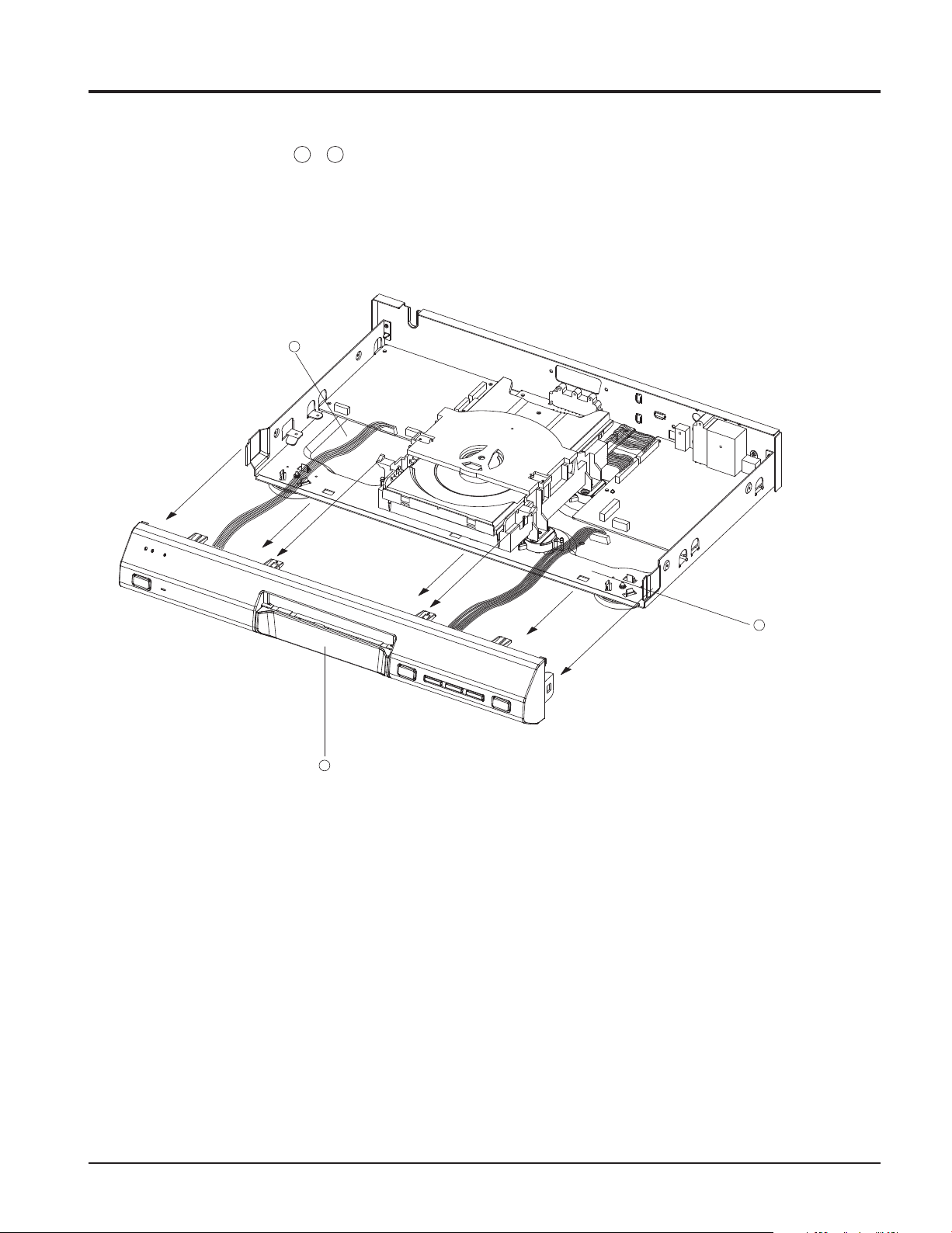
2-3 Ass'y Front-Cabinet Removal
1
1) Disconnect wire , (See Fig. 2-3)
2
1
3
FRONT-ASS'Y
2
Fig. 2-3 Ass'y Front-Cabinet Removal
2-3

2-3 Ass'y Front-Cabinet Removal
1
1) Disconnect wire , (See Fig. 2-3)
2
1
3
FRONT-ASS'Y
2
Fig. 2-3 Ass'y Front-Cabinet Removal
2-3
2-3 Ass'y Front-Cabinet Removal
1
1) Disconnect wire , (See Fig. 2-3)
2
1
3
3 FRONT-ASS'Y
Fig. 2-3 Ass'y Front-Cabinet Removal
2
2-3

2-3 Ass'y Front-Cabinet Removal
1
1) Disconnect wire , (See Fig. 2-3)
2
1
3
FRONT-ASS'Y
2
Fig. 2-3 Ass'y Front-Cabinet Removal
2-3

2-4 Ass'y Deck Removal
1) Disconnect wire housing and flat-cable .
2) Remove 4 screws and lift the deck Ass'y up.
3
1 2
3
SCREWS(4EA)
2
1
1
2-4
Fig. 2-4 Ass'y Deck Removal

2-4 Ass'y Deck Removal
1) Disconnect wire housing and flat-cable .
2) Remove 4 screws and lift the deck Ass'y up.
3
1 2
3
4 SCREWS
2
1
2-4
Fig. 2-4 Ass'y Deck Removal

2-5 PCB Removal (2CH, 1SCART)
1) Disconnect wire ,
2) Remove Screws , , , (See Fig. 2-5)
4
4 SCREWS
1
2
3 4 5 6
SMPS PCB
5
1
2 SCREWS
SCART PCB
2
MPEG-PCB
6
4 SCREWS
Fig. 2-5 PCB Removal
3
4 SCREWS
2-5

2-6 PCB Removal (2CH)
1) Disconnect wire
2) Remove Screws , , (See Fig. 2-6)
4
4 SCREWS
1
3 4 5
SMPS PCB
5
4 SCREWS
1
MPEG-PCB
Fig. 2-6 PCB Removal
3
3 SCREWS
2-6

2-7 PCB Removal (5.1CH, 1SCART)
1) Disconnect wire ,
2) Remove Screws , , , (See Fig. 2-5)
4 4 SCREWS
1
2
3 4 5 6
SMPS PCB
5 2 SCREWS
1
SCART PCB
2
6 4 SCREWS
MPEG-PCB
Fig. 2-7 PCB Removal
3 6 SCREWS
2-7

2-8 PCB Removal (5.1CH)
1) Disconnect wire
2) Remove Screws , , (See Fig. 2-8)
4 4 SCREWS
1
3 4 5
SMPS PCB
1
5 4 SCREWS
MPEG-PCB
Fig. 2-8 PCB Removal
3 5 SCREWS
2-8

3. Exploded Views
3-1 Cabinet and Main Frame Section
15
15
13
15
14
14
8
16
16
9
14
6
4
5
3
7
4
6
5
3-1
14
16
10
11
12
1
2

3. Exploded Views
3-1 Cabinet and Main Frame Section
15
15
13
15
14
14
8
16
16
14
7
9
6
5
4
3
6
4
3-1
12
14
11
16
10
1
2

3. Exploded Views
3-1 Cabinet and Main Frame Section
15
15
13
15
14
14
8
16
14
9
16
6
4
5
3
7
4
6
5
14
16
10
11
12
1
2
3-1

3. Exploded Views
3-1 Cabinet and Main Frame Section
15
13
16
14
15
9
6
15
14
3
14
8
16
14
16
10
7
6
12
11
4
1
5
4
2
3-1

SET EXPLODED - VIEW LIST
NO.
1
2
3
4
5
6
7
8
9
10
11
12
CODE NO. PART NAME DESCRIPTION Q'TY REMARK
DP00-A0001
DP00-A0002
DP00-M0019
DP00-M0023
DP00-L0003
DP00-L0004
DP00-M0022
DP02-A0011A
APSM-00002A
APSC-00001A
APMP-00002A
DPEX-10002
FRONT-ASS'Y
DOOR-ASS'Y
CHASSIS-BOTTOM
FOOT-FRONT
CUSHION-FRONT
CUSHION-BOTTOM
HOLDER-CHASSIS
LOADER-ASS'Y
CHASSIS-REAR
ASS'Y-PCB SMPS
ASS'Y-PCB SCART
ASS'Y-PCB MPEG
MOLD + PCB ASS'Y
ASS'Y, SILVER
SECC T1.0
ABS 94HB GRY
EVA 60 T3.0
EVA 60 T2.0
HIPS GRY
DM-L1
SECC TO.8
ASS'Y
ASS'Y
ASS'Y
1
1
1
2
2
2
4
1
1
1
1
1
13
14
15
16
DP00-M0021
DP00-P0001A
DP00-P0003
DP00-P0011A
CABINET-TOP
SCREW 3 * 10 YEL
SCREW 3 * 8
SCREW 3 * 8 YEL
SECC TO.6
TAP TITLE 3 * 10 YEL
TAP TITLE 3 * 8
TAP TITLE
3 * 8 YEL
1
17
5
14
COLOR
3-2

SET EXPLODED - VIEW LIST
NO.
1
2
3
4
5
6
7
8
9
10
11
12
CODE NO. PART NAME DESCRIPTION Q'TY REMARK
DP01-A0003
DP01-A0004
DP00-M0019
DP00-M0023
DP00-L0003
DP00-L0004
DP00-M0022
DP00-A0007
DP00-M0020
APSM-00002A
APSC-00001A
APMP-00002A
FRONT-ASS'Y
DOOR-ASS'Y
CHASSIS-BOTTOM
FOOT-FRONT
CUSHION-FRONT
CUSHION-BOTTOM
HOLDER-CHASSIS
LOADER-ASS'Y
CHASSIS-REAR
ASS'Y-PCB SMPS
ASS'Y-PCB SCART
ASS'Y-PCB MPEG
MOLD + PCB ASS'Y
ASS'Y, SILVER
SECC T1.0
ABS 94HB GRY
EVA 60 T3.0
EVA 60 T2.0
HIPS GRY
DM-L1
SECC TO.8
ASS'Y
ASS'Y
ASS'Y
1
1
1
2
2
2
4
1
1
1
1
1
13
14
15
16
DP00-M0021
DP00-P0001A
DP00-P0003
DP00-P0011
CABINET-TOP
SCREW 3 * 10 YEL
SCREW 3 * 8
SCREW 3 * 8 YEL
SECC TO.6
TAP TITLE 3 * 10 YEL
TAP TITLE 3 * 8
TAP TITLE
3 * 8 YEL
1
7
5
14
COLOR
3-2

SET EXPLODED - VIEW LIST
NO.
1
2
3
4
5
6
7
8
9
10
11
12
CODE NO. PART NAME DESCRIPTION Q'TY REMARK
DP01-A0010
DP01-M0027
DP00-M0019
DP00-M0039
DP00-L0003
DP00-L0004
DP01-M0038
DP02-A0012
DP01-M0025
APSM-00002A
APSC-00001A
APMP-00002A
FRONT-ASS'Y
DOOR-TRAY
CHASSIS-BOTTOM
FOOT-FRONT
CUSHION-FRONT
CUSHION-BOTTOM
HOLDER-CHASSIS
LOADER-ASS'Y
CHASSIS-REAR
ASS'Y-PCB SMPS
ASS'Y-PCB SCART
ASS'Y-PCB MPEG
MOLD+PCB ASS'Y
SILVER
SECC T1.0
ABS 94HB GRY
EVA60 T3.0
EVA60 T2.0
HIPS GRY
DM-L2
SECC T0.8
ASS'Y
ASS'Y
ASS'Y
1
1
1
2
2
2
4
1
1
1
1
1
13
14
15
16
DP00-M0021
DP00-P0001A
DP00-P0003
DP00-P0011
CABINET-TOP
SCREW 3 * 10 YEL
SCREW 3 * 8
SCREW 3 * 8 YEL
SECC T0.6
TAP TITLE 3 * 10 YEL
TAP TITLE 3 * 8
TAP TITLE 3 * 8 YEL
1
7
5
14
COLOR
3-2

SET EXPLODED - VIEW LIST
NO.
1
2
3
4
5
6
7
8
9
10
11
12
CODE NO. PART NAME DESCRIPTION Q'TY REMARK
DP01-A0001
DP01-A0002
DP00-M0019
DP00-M0023
DP00-L0003
DP00-L0004
DP00-M0022
DP00-A0007
DP00-M0020
APSM-00002A
APSC-00001A
APMP-00002A
FRONT-ASS'Y
DOOR-ASS'Y
CHASSIS-BOTTOM
FOOT-FRONT
CUSHION-FRONT
CUSHION-BOTTOM
HOLDER-CHASSIS
LOADER-ASS'Y
CHASSIS-REAR
ASS'Y-PCB SMPS
ASS'Y-PCB SCART
ASS'Y-PCB MPEG
MOLD + PCB ASS'Y
ASS'Y, SILVER
SECC T1.0
ABS 94HB GRY
EVA 60 T3.0
EVA 60 T2.0
HIPS GRY
DM-L1
SECC TO.8
ASS'Y
ASS'Y
ASS'Y
1
1
1
2
2
2
4
1
1
1
1
1
13
14
15
16
DP00-M0021
DP00-P0001A
DP00-P0003
DP00-P0011
CABINET-TOP
SCREW 3 * 10 YEL
SCREW 3 * 8
SCREW 3 * 8 YEL
SECC TO.6
TAP TITLE 3 * 10 YEL
TAP TITLE 3 * 8
TAP TITLE 3 * 8 YEL
1
7
5
14
COLOR
3-2

3-3 Front Exploded views (push - s/w)
14
14
17
7
6
13
17
16
4
9
12
14
8
1
15
5
10
11
11
3-3
3
2
 Loading...