

Page 1
30” WIDE TFT-LCD TV
SERVICE MANUAL
CHASSIS:
MODEL: LT-30FEP / LT-30FLP / LT-30FTP
Page 2

CONTENTS
Contents ................................................................................................................ 2
Safety Precautions ............................................................................................3
Specifications ..................................................................................................... 4
Control Descriptions ....................................................................................... 6
Adjustment...........................................................................................................9
Troubleshooting..................................................................................................11
Disassembly Instructions ..............................................................................13
Replacement Parts List ............................................................................... 19
Schematic Diagram ......................................……………………….............................26
PCB Printings ............................................................................……………27
2
Page 3
SAFETY PRECAUTIONS
Important Safety Notice
Many electrical and mechanical parts in this chassis have special safety-related characteristics. These
parts are identified by in the Schematic Diagram and Replacement Parts List.
It is essential that these special safety parts should be replaced with the same components as
recommended in this manual to prevent Shock, Fire, or other Hazards.
Do not modify the original design without permission of manufacturer.
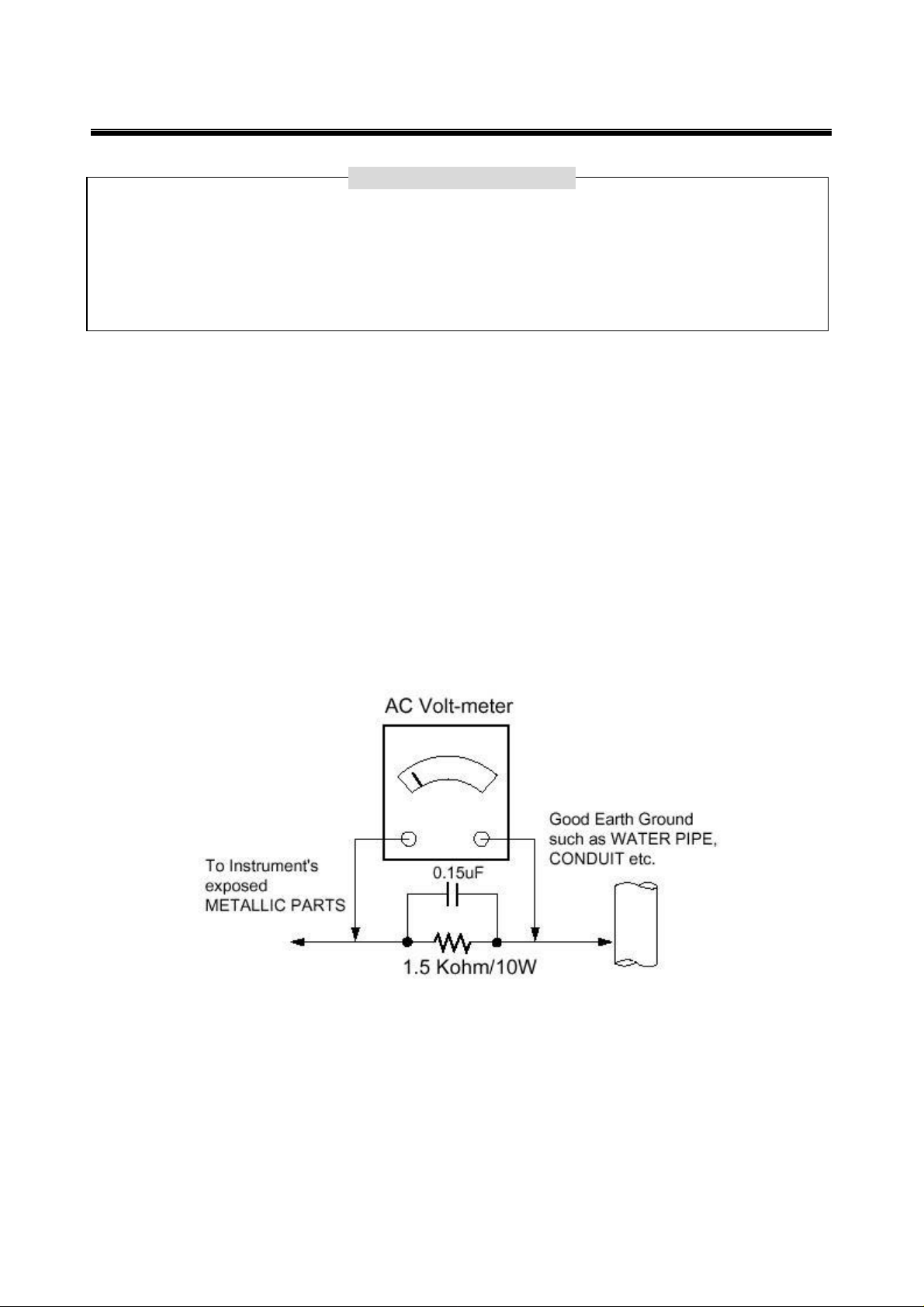
Leakage Current Hot Check (See below Figure)
Plug the AC cord directly into the AC outlet.
Do not use a line Isolation Transformer during this check.
Connect 1.5K/10watt resistor in parallel with a 0.15uF capacitor between a known good earth ground (Water
Pipe, Conduit, etc.) and the exposed metallic parts.
Measure the AC voltage across the resistor using AC voltmeter with 1000 ohms/volt or more sensitivity.
Reverse plug of the AC cord into the AC outlet and repeat AC voltage measurements for each exposed
metallic part. Any voltage measured must not exceed 0.75 volt RMS, which is, corresponds to 0.5mA.
In case any measurement is out of the limits specified, there is possibility of shock hazard and the set must
be checked and repaired before it is returned to the customer.
Leakage Current Hot Check circuit
3
Page 4
SPECIFICATIONS
Note: Specifications and others are subject to change without notice for improvement.
1. Power requirement:
‥AC 110-240V, 50/60Hz (Cold SMPS)
/ DC 24V ADAPTOR
2. Tuning system:
‥FVS, 100 program memory
3. Sound output:
‥105W+10W
4. Intermediate Frequency (IF):
‥Vision IF ; 38.9MHz
‥Color IF ; 34.47MHz(PAL) / 35.32MHz(NTSC)
‥Sound IF ; 33.4MHz (B/G) / 32.9MHz(I,I/I) /
32.4MHz(D/K, K1) / 34.4MHz(M)
5. Power consumption:
‥130W(3W-ST-BY)
6. Antenna input impedance:
‥VHF/UHF 75ohm , TIF
7. Voice coil impedance:
‥4ohm option
8. OSD (On Screen Display):
‥Window Type
Receiving system
No.
System
1 PAL-B O O O
2 PAL-G O O O
3 PAL-I, I/I O O O
4 PAL-D O O O
5 PAL-K O O O
6 SECAM-B O O O
7 SECAM-G O O O
8 SECAM-D O O O
9 SECAM- K O O O
10 SECAM-K1 O O O
11 SECAM-I (6.0) O O O
12 NTSC-3.58/4.5 X X O
13 NTSC-3.58/5.5 X X O
14 NTSC-3.58/6.0 X X O
15 NTSC-3.58/6.5 X X O
16 NTSC-3.58/4.5(5.0) X X O
17 NTSC-4.43/5.5 X X O
18 NTSC-4.43/6.0 X X O
19 NTSC-4.43/6.5 X X O
20 PAL 5.5/60HZ O O O
21 PAL 6.0/60HZ O O O
22 PAL 6.5/60HZ O O O
23 SECAM 5.5/60HZ O O O
24 SECAM 6.0/60HZ O O O
25 SECAM 6.5/60HZ O O O
26 SECAM L/L’ X O X
TOTAL SYSTEM 17 18 25
Model No.
9. External in/output: Headphone, SCART or
Phone Jack: Option
‥Audio-In ; 0.4Vrms, over 10Kohm
‥Video-In/Out ; 1Vp-p,over 75ohm
‥R.G.B In ; 0.7Vp-p
10. Function:
‥CATV/Hyper band
‥Auto Program
‥Manual Program
‥Auto Sleep
‥Recall
‥Quick view
‥ACMS(Auto channel Memory System)
‥PSM(Picture Status memory)
‥SSM(Sound Status memory)
‥PIP(PICTURE I RICTURE)
‥ARC(ASPECT RATIO CONTROL)
LT-30FEP LT-30FLP LT-30FTP
4
Page 5
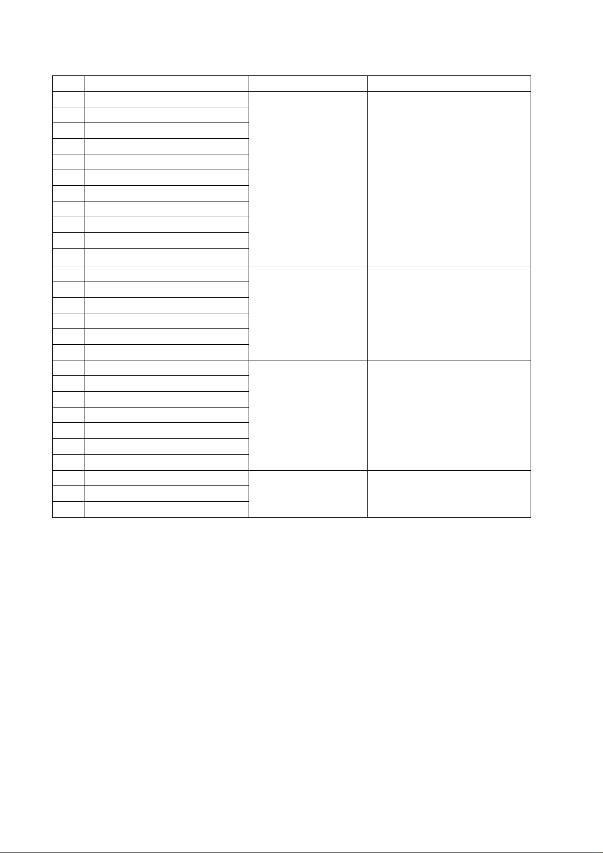
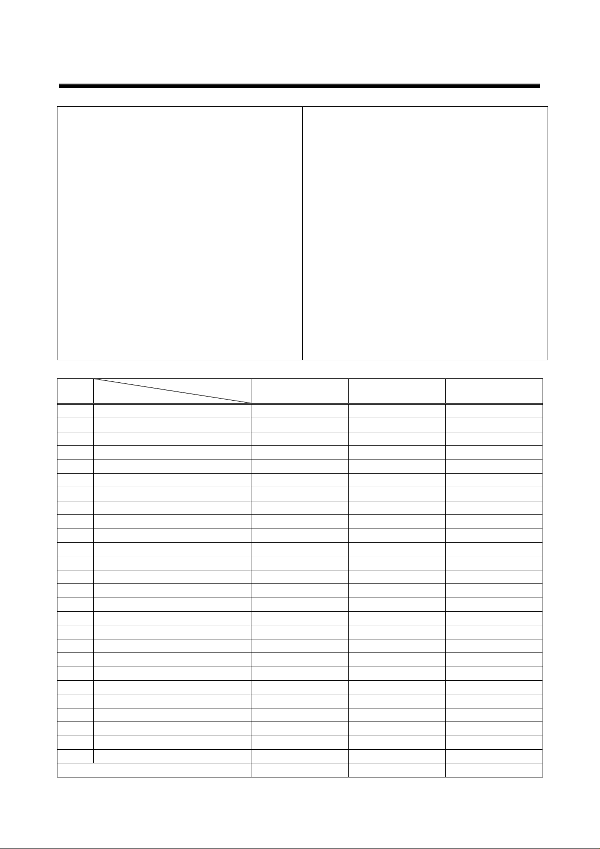
TABLE1. RECEIVING SYSTEM (26 SYSTEM)
No.
Receiving System Function Receiving Channel
1 PAL-B
2 PAL-G
3 PAL-I, I/I
4 PAL-D
5 PAL-K
6 SECAM-B
7 SECAM-G
Reception of broadcast
and play-back for Video
Tape Recorder
8 SECAM-D
9 SECAM- K
10 SECAM-K1
11 NTSC-M
12 SECAM-L/L’
13 NTSC-4.43/5.5
14 NTSC-4.43/6.0
15 NTSC-4.43/6.5
Play-back for special
Video Tape Recorder
16 SECAM-I (6.0MHZ)
17 SECAM-L (VIDEO IN)
18 NTSC 3.58/4.5MHZ/50HZ
19 PAL 5.5MHZ/60HZ
20 PAL 6.0MHZ/60HZ
21 PAL 6.5MHZ/60HZ
22 SECAM 5.5 MHZ /60HZ
Play-back for special
Video Tape/Video disk
player
23 SECAM 6.0 MHZ /60HZ
24 SECAM 6.5 MHZ /60HZ
25 NTSC-3.58/5.5MHZ
26 NTSC-3.58/6.0MHZ
27
NTSC-3.58/6.5MHZ
Play-back for special
Video Tape Recorder
VHF Band
PAL/SECAM-B: 2-12
PAL/SECAM-D: 1-12
SECAM-K1: 2-9
NTSC-M (US): 2-13
NTSC-M (JAPAN): 1-12
UHF Band
PAL/SECAM-G: 21-69
PAL-I: 21-69
SECAM-K: 21-69
PAL-K: 13-56
NTSC-M (US): 14-78
NTSC-M (JAPAN): 13-62
5
Page 6
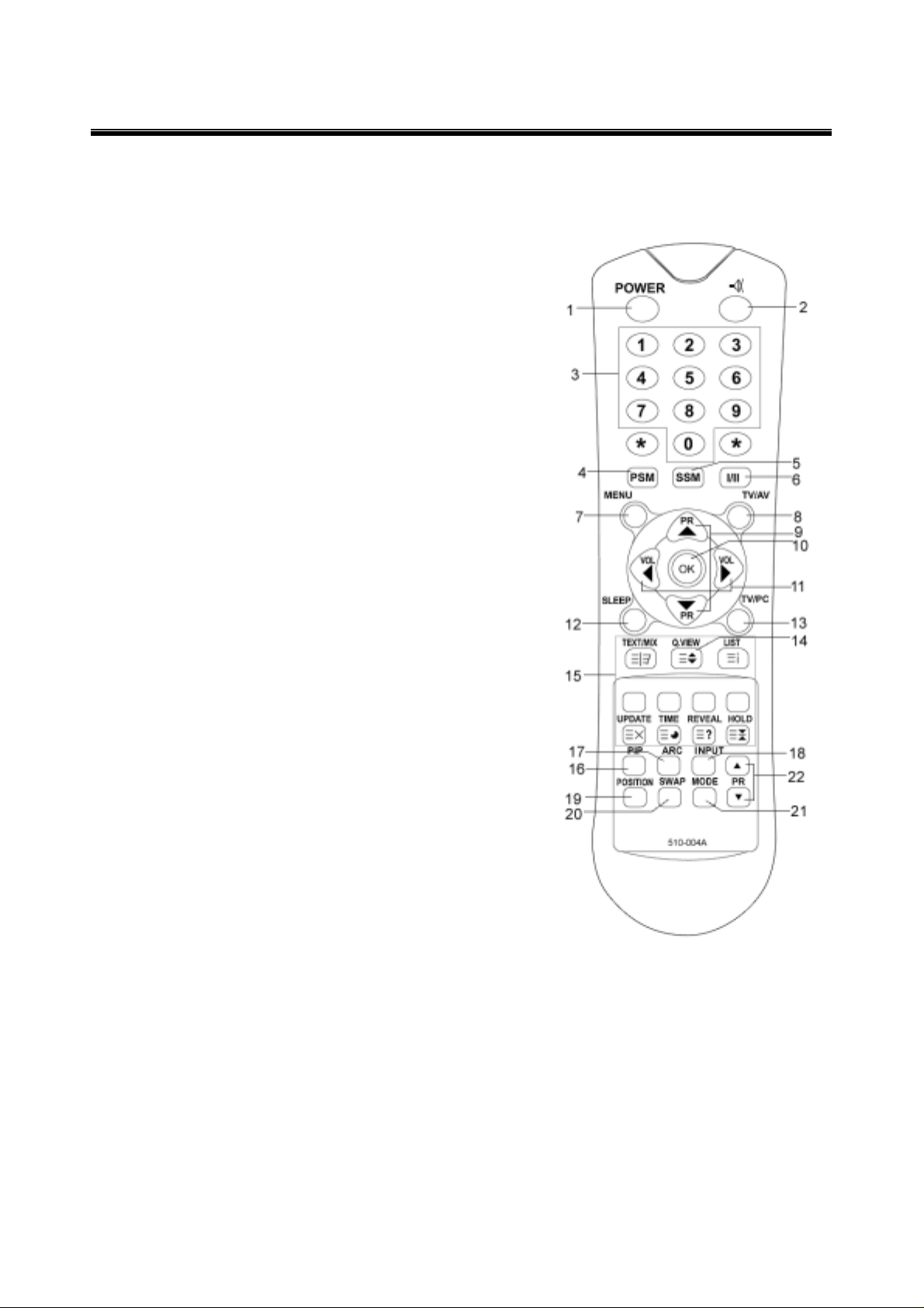
CONTROL DESCRIPTIONS
All the functions can be controlled with the remote control handset.
Some functions can also be adjusted with the buttons on the front panel of the set.
Remote controller
Before you use the remote controller, please install the batteries.
1. POWER
Turns the TV on from standby or off to standby mode.
2. MUTE
Turns the sound on and off.
3. NUMBER buttons
Selects programme numbers.
4. PSM (Picture Status Memory)
Recalls your preferred picture setting
5. SSM (Sound Status Memory)
Recalls your preferred sound setting
8. TV/AV
Selects TV, SCART, VIDEO, S-VIDEO or PC mode.
Clears the menu from the screen.
7. MENU
Displays a main menu.
6. I/II
Selects the language during dual language broadcast.
Selects the sound output.
9. SLEEP
Sets the sleep timer.
10. TV/PC
Selects TV or PC mode directly.
11. PR▲▼ (Programme Up/Down)
Selects next programme or a menu item.
12. VOL◀▶ (Volume Up/Down)
Adjusts the sound level.
Adjusts menu settings.
13. OK
Accepts your selection or displays the current mode.
14. TELETEXT Buttons
These buttons are used for TELETEXT.
For further details, see the ‘TELETEXT’ section.
15. Q.VIEW
Returns to the previously viewed programme.
Note: In TELETEXT mode,
The Q.VIEW button is used for TELETEXT function.
16. PIP
Displays a PIP(Picture In Picture).
17. ARC
Selects a screen mode-, 16:9, 14:9, ZOOM 1:1 and Auto Wide.
18. INPUT
Selects the AV source of sub picture in PIP mode.
19. POSITION
Selects a position of PIP.
20. SWAP
Switches a main picture for sub picture.
21. MODE
Selects a PIP screen mode. – 16:1, 9:1, double window and scan mode
22. ▼ ▲
Selects a programme when RF signal is displayed in PIP mode.
6
Page 7
CONTROL DESCRIPTIONS
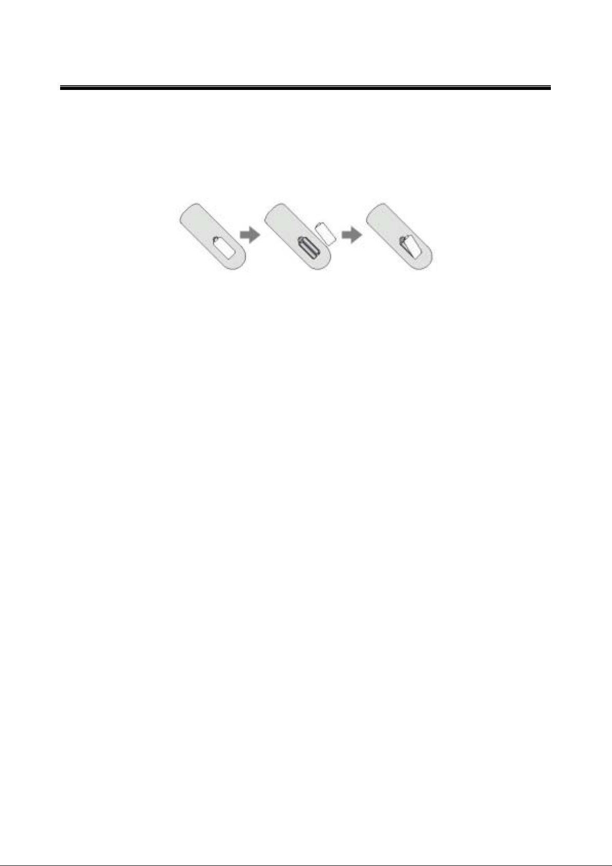
Battery installation
▶Inserting batteries
1. Remove the battery cover by pulling it upward in the direction shown by the arrow.
2. Insert the batteries with correct polarity (“+" to "+", and "-" to "-”).
3. Replace the battery compartment cover.
* Install two high-quality 1.5V "AAA" alkaline batteries. Don't mix old batteries with new batteries.
*Remove batteries when you won't use the remote controller for long time. Liquid leakage from old batteries
may cause operation failure.
Notes for using remote controller
• Make sure there are no objects between the remote controller and its sensor.
• Don't place the remote control near a heater or in damp place. Strong impact to the remote control may
cause operation failure.
• Signal from the remote control may be disturbed by sunlight or other bright light. In this case, darken the
room or move the TV.
7
Page 8

DESCRIPTION OF CONTROLS
<<CONTROLLER OF PANEL>>
1. MENU
Displays a menu.
2. + PR - (Programme Up/Down)
Selects a programme or a menu item.
3. POWER STANDBY INDICATOR
Illuminates in red when the TV is in standby mode./ Illuminates in green when the TV is switched on.
4. POWER Switches TV set on or off.
5. Remote control sensor Accepts the IR signal of remote controller.
6. +VOL- (Volume Up/Down)
Adjusts the volume level./ Adjusts menu settings.
7. TV/AV
Selects TV, SCART, VIDEO, S-VIDEO, PC Analog or PC Digital mode. / Clears the menu from the screen.
6
7
1. DC 24V adaptor input
2. PC/DTV INPUT
3. DVI
4. PC Audio IN
Connect the audio cable from the PC to the PC Audio IN of the set.
5. HEADPHONE out
Connect a headphone to this socket.
6. S-VIDEO input
Connect the output of an S -VIDEO VCR to the S-VIDEO input.
Connect the audio outputs of an S-VIDEO VCR to the Audio IN (L(MONO), R).
7. SCART2
8. SCART1
Connect the Audio/Video outputs of external equipment to scart jack.
9. Ant. (Antenna input)
1
2
3
4
5
8
Page 9

ADJUSTMENT
Safety Precautions
1. Never disconnect leads while the TV receiver is on.
2. Don't short any portion of circuits while power is on.
3. The adjustment must be done by the correct appliances. But this is changeable in view of
productivity.
4. Unless otherwise noted, set the line voltage to 230Vac 10%, 50Hz. / 110Vac, 60Hz
Test Equipment required
1. RF signal generator (with pattern generator)
2. Multi meter (volt meter)
3. Oscilloscope
4. LCD Color analyzer
RF AGC (Automatic Gain Control) Adjustment
The RF AGC was aligned at the time of manufacturing for optimum performance over a wide range
conditions. Readjustment of RF AGC should not be necessary unless unusual local conditions exist, such as ;
1) Channel interference in a CATV system.
2) Picture bending and/or color beats, which are unusually due to excessive RF signal input when the
receiver is too close to a transmitting tower or when the receiver is connected to an antenna
distribution system where the RF signal has been amplified. In this case, the input signal should be
attenuated (with pad or filter) to a satisfactory level.
3) Picture noise caused by "broadcast noise" or weak signal. If the broadcast is "clean" and the RF
signal is at least 1mV (60dBu), the picture will be noise free in any area.
Adjusting RF AGC to one end of rotation will usually cause a relatively poor signal to noise ratio; Adjusting to
the other end of rotation will usually cause a degradation of over load capabilities resulting in color beats or
adjacent channel interference.
9
Page 10

ADJUSTMENT
OPTION Adjustment (SVC MODE:OPTION-1, OPTION-2)
NOTE: When the EEPROM has been replaced, the Option data should be restored as the function of
individual system and specification.
1) Press the MENU buttons on both TV set and Remote Controller at the same time to get into SVC mode.
2) Press the Yellow button several times to find OPTION-1 or OPTION-2.
3) Input the corresponding OPTION data referring to Table below with the numeric buttons 0~9.
Option Table
LT-30FEP LT-30FLP LT-30FTP REMARK
200PR 0 0 0
TEXT 1 1 1
OPTION
1
OPTION
2
TOP 1 1 1
SCART 1 1 1 Set 0 in case of YUV model.
ACMS 1 1 1
CH+AU 0 0 0
SYS 0 1 2 1
DUAL 1 1 1
MONO 0 0 0
A2 ST 1 1 1
VOL 0 0 0
AV1 1 1 1
KEY 0 0 0
LANG 1 1 1
T-LAN 0 0 0 Set proper Teletext language
10
Page 11

No Picture &
Sound OK
Check Vcc, X-tal &
TROUBLESHOOTING
No
No
Is OSD O.K?
Yes
Check IC201
Check IC01
L102(DCLK)
R104(LHSYNC)
R103(LVSYNL)
IIC of IC201
Pin 32/39 O.K?
O.K ?
Check IC201
Video Inputs
Pin78/80/82/96/97
/98/100/102
Yes
Check signals from
IC01~IC402.
Check Vcc of
IC402
No Yes
11
Page 12

TROUBLESHOOTING
No Sound &
Picture OK
Check IC601
Vcc / X-tal / IIC
No
Check IC601
Inputs ( Pin
47/48/50/51/53/5
4/56/57)
Yes
Check IC601
Outputs Pin27/28
Yes
Check IC651,
IC652
Outputs (Pin7/11)
Yes
Check
Headphone
No
No
Check appropriate
signal inputs from
IC601 to signal
source.
Check IC651,
IC652 Vcc
No Text
jack of J402
Check IC101
Pin12 (CVBS)
No
Check CVBS
signal from Pin70
Yes
of IC501 to Pin12
of IC101
Check Pin38~41
of IC101
(R.G.B.FB)
Check
Yes
No
Replace IC101
Pin1/2/3/79
of IC501
12
Page 13

EXPLODED VIEW PARTS LIST
NO. PART NO. DESCRIPTIONS
14
Page 14

REPLACEMENT PARTS LIST
The components identified by mark L is critical for
safety.
Replace only with part number specified.
For Capacitor & Resistors,
the charactors at 2nd 3rd
digit in the P/No. means as
follows
LOCA. NO PART NO DESCRIPTION LOCA. NO PART NO DESCRIPTION
IC
IC1 1ICMI5550MBS IC,SDA5550M Q740 0TRKE3875STS TRANSISTOR,KTC3875S
IC2 1ICSE24C16TS IC,16K Q802 0TRKE3875STS TRANSISTOR,KTC3875S
IC3 0ISSY32P00BD IC,SOCKET,32-PIN Q805 0TRKE3875STS TRANSISTOR,KTC3875S
IC3 1ICSY12JC0BS IC,512K*8BIT 120NS Q921 0TRKE3875STS TRANSISTOR ,KTC3 87 5S
IC4 0ICHNV8100BS IC,128K x 8bit, SRAM Q951 0TRKE3875STS T RA NS ISTOR,KTC 3875S
IC6 0ICKE7027FTS IC,KIA7027AF Q1001 0TRKE3875S TS TRA NSISTOR,KTC 3875S
IC11 1ICIR33Y00TS IC,3.3V, 1A Q1002 0TRKE102S0 TS T RA NS ISTOR,KRC 102S
IC12 1ICIR25Y00TS IC,2.5V, 1A Q1003 0TRKE3875S TS T RA NS ISTOR,KTC387 5S
IC101 1ICMX88L285 IC,MX88L285 Q1007 0TRKE3875S TS TRA NSISTOR ,KTC3875S
IC161 0ICKE7027FTS IC,KIA7027AF, 2.7V RESET Q1008 0TRKE3875S TS T RA NS ISTOR ,KTC3875S
IC171 1ICW B986532S IC,SDRAM Q1009 0TRKE3875S TS TRA NSISTOR,KTC 3875S
IC172 1ICW B986532S IC,SDRAM Q1152 0TRKE3875S TS TRA NSISTOR,KTC 3875S
IC201 1ICMI9427BBS IC,VSP9427B DIODE
IC271 1ICIR18Y00TS IC,1.8V, 1A D652 0DHKEKD S181S CHIP DIODE,KD S 181
IC272 1ICIR33Y00TS IC,3.3V, 1A D654 0DHKEKD S181S CHIP DIODE,KD S 181
IC301 1ICAD98820BS IC,AD9882A D 802 1DHIR1545CTS DIODE,D2PAK, 45V 15A
IC302 1ICST24C02WS IC,EEPROM D 803 1DHIR1545CTS DIODE,D2PAK, 45V 15A
IC402 1ICNS90C383S IC,LVDS TR AN SM ITTER D831 1DHSTYW020TS CHIP DIODE, SM BYW 02-200
IC601 1ICMI3410DBS IC,MSP3410D D 83 2 1DHSTYW020TS CHIP DIODE,SMB YW02-200
IC602 0ICKE7042FTS IC,KIA7042AF D833 1DHSTYW020TS CH IP DIODE,SM B YW02-200
IC651 1ICSA42820AD IC,AMP D834 1DHSTYW 020TS CH IP DIODE,SM B YW 02- 200
IC652 1ICSA42820AD IC,AMP D835 1DHSTYW 020TS CH IP DIODE,SM B YW 02- 200
IC685 1ICSTVN02NBD IC,VN02N D836 1DHSTYW0 20TS CHIP DIODE,SM B YW02-200
IC691 1ICST2822MBD IC,TDA2822 D901 0DHKEKD S22 6S CHIP DIODE,KD S226
IC731 1ICPH8601TT S IC,TDA8601 D902 0DHKEKD S 226S CHIP DIODE,KD S 226
IC802 1ICNSLM5R0BS IC,LM2576HVSX- 5.0 D903 0DHKEKD S 226S CHIP DIODE ,KD S 226
IC803 1ICNSLM120B S IC,LM2678S-12 D904 0DHKEKD S 226S CHIP DIODE,KD S 226
IC805 0ICVI4925DTS IC,SI7925 DY TP D905 0DHKEKD S 226S CHIP DIODE,KD S 22 6
IC821 1ICIR33Y00TS IC,3.3V, 1A D906 0DHKEKDS226S CHIP DIODE,KD S226
IC831 0ICKE78R08ID IC,KIA78R08API D907 0DHKEKD S22 6S CHIP DIODE,KD S226
IC832 0ICKE7805AT S IC,KIA7805AF D908 1DDRO 41480TA DIODE,1N4148
IC841 1ICIR33Y00TS IC,3.3V, 1A D1001 1DDSKEU 1Z0TA D IODE,FAS T RE CO VERY
IC842 1ICSB396625D IC,LP3966ET-2.5 D2001 1DDRO 41480TA DIODE,1N4148
IC843 1ICIR25Y00TS IC,2.5V, 1A ZD1 1DZSC5226B TS C HIP ZENER,3.3V
IC844 1ICIR33Y00TS IC,3.3V, 1A ZD601 1D ZSC 5237B TS C HIP ZENER,8.2V
IC851 1ICIR33Y00TS IC,3.3V, 1A ZD731 1D ZSC 5237B TS C HIP ZENER,8.2V
IC901 1ICST24C02WS IC,24C020 ZD901 1D ZSC 5231B TS CHIP ZENER,5.1V
IC902 1ICPH74F08TS IC,74F08 ZD902 1DZSC5231BTS CHIP ZENE R,5.1V
IC1001 0ICKE7805ATS IC,KIA7805AF 5.0V 1A ZD1002 1DZSSHZT33TA DIODE,33V
IC1003 1ICRO61 61FTS IC,DC/DC CONVER TER ZD1005 1DZSC523 1BTS CHIP ZENER,5 .1V
IC1151 1ICST4053BMS IC,HCF4053BM 1 ZD1006 1D ZSC 5231B TS CHIP ZENER,5.1V
Q1 1ICFC2N700TR IC,2N7000TA COIL
Q2 1ICFC2N700TR IC,2N7000TA L16 0LBSS601FJTS CHIP BEAD,600 O HM
TR L17 0LBSS601FJTS CH IP BEA D ,600 O HM
Q3 0TRKE387 5STS TRANS ISTOR ,KTC3875S L103 0LBSS601FJTS CHIP BEAD,600 OHM
Q201 0TRKE1504STS TRANS ISTOR,KTA 1504S L104 0LBSS 601FJTS CHIP BEAD ,600 OHM
Q202 0TRKE1504STS TRANS ISTOR,KTA 1504S L105 0LBSS 601FJTS CHIP BEAD ,600 OHM
Q621 0TRKE1504STS TRANS ISTOR,KTA 1504S L106 0LBSS 601FJTS CHIP BEAD ,600 OHM
Q622 0TRKE1504STS TRANS ISTOR,KTA 1504S L107 0LBSS 601FJTS CHIP BEAD ,600 OHM
Q623 0TRKE1504STS TRANS ISTOR,KTA 1504S L108 0LBSS 601FJTS CHIP BEAD ,600 OHM
Q651 0TRKE3875STS TRANS ISTOR,KTC38 75S L109 0LBSS601FJTS CHIP BEAD,600 OHM
Q652 0TRKE3875STS TRANS ISTOR,KTC38 75S L110 0LBSS601FJTS CHIP BEAD,600 OHM
Q685 0TRKE3875STS TRANS ISTOR,KTC38 75S L113 0LBSS601FJTS CHIP BEAD,600 OHM
Q686 0TRKE3875STS TRANSISTOR,KTC3875S
DH:Chip Diode
DZ:Zener Diode
DD:Rectifier Diode
DS:Schottky Diode
TR:Transistor
LB: Bead Core
LY:Array Bead
LA:Inductor
LR:Choke Coil
XT:Crystal
Page 15

The components identified by mark L is critical for
safety.
Replace only with part number specified.
For Capacitor & Resistors,
the charactors at 2nd 3rd
digit in the P/No. means as
follows
CH:Chip Capacitor
CE:Electrolytic Capacitor
CB:Bipolar Capacitor
CQ: Poly Capacitor
CT:Tantal Capacitor
LOCA. NO PART NO DESCRIPTION LOCA. NO PART NO DESCRIPTION
L171 0LBSS601FJTS CHIP BEAD,600 OHM L2001 0LASS100FKTS CHIP COIL,10UH
L172 0LBSS601FJTS CHIP BEAD,600 OHM CRYSTAL
L201 0LBSS601FJTS CHIP BEAD,600 OHM X1 0XTKI06M00TS CRYSTAL,6.0MHZ
L202 0LBSS601FJTS CHIP BEAD,600 OHM X101 0XTKI143180S CRYSTAL,14.318MHZ
L203 0LBSS601FJTS CHIP BEAD,600 OHM X201 0XTKI20M25TS CRYSTAL,20.25MHZ
L204 0LBSS601FJTS CHIP BEAD,600 OHM X601 0XTKI184320D CRYSTAL,18.432MHZ
L251 0LBSS601FJTS CHIP BEAD,600 OHM CAPACITOR
L271 0LBSS601FJTS CHIP BEAD,600 OHM C1 0CHSS104DZTS CHIP CAP.0.1UF
L301 0LBSS601FJTS CHIP BEAD,600 OHM C2 0CHSS104DZTS CHIP CAP.0.1UF
L302 0LBSS601FJTS CHIP BEAD,600 OHM C3 0CHSS104DZTS CHIP CAP.0.1UF
L307 0LBS S 6 0 1FJTS CHIP BEAD ,600 O H M C4 0CASH 10 0CMTS CAN,CAP.10U F 16 V
L312 0LBSS601FJTS CHIP BEAD,600 OHM C6 0CHSS104DZTS CHIP CAP.0.1UF
L313 0LBS S 6 0 1FJTS CHIP BEAD ,600 O H M C7 0CASH 33 0CMTS CAN,CAP.33U F 16 V
L314 0LBSS601FJTS CHIP BEAD,600 OHM C8 0CHSS104DZTS CHIP CAP.0.1UF
L315 0LBSS601FJTS CHIP BEAD,600 OHM C9 0CHSS101DJTS CHIP CAP.100PF
L317 0LBSS601FJTS CHIP BEAD,600 OHM C10 0CHSS101DJTS CHIP CAP.100PF
L421 0LBSS601FJTS CHIP BEAD,600 OHM C11 0CHSS101DJTS CHIP CAP.100PF
L422 0LBSS601FJTS CHIP BEAD,600 OHM C12 0CHSS104DZTS CHIP CAP.0.1UF
L431 0LBSS3580RTR BEAD CORE,1UH DUAL C13 0CHSS330DJTS CHIP CAP.33PF
L601 0LBSS601FJTS CHIP BEAD,600 OHM C14 0CHSS330DJTS CHIP CAP.33PF
L602 0LASS100FKTS CHIP COIL,10UH C15 0CHSS104DZTS CHIP CAP.0.1UF
L603 0LBSS601FJTS CHIP BEAD,600 OHM C16 0CHSS104DZTS CHIP CAP.0.1UF
L604 0LBSS601FJTS CHIP BEAD,600 OHM C17 0CHSS104DZTS CHIP CAP.0.1UF
L651 0LBSS3580RTR BEAD CORE,1UH DUAL C18 0CHSS104DZTS CHIP CAP.0.1UF
L691 0LBSS601FJTS CHIP BEAD,600 OHM C19 0CASH100CMTS CAN,CAP.10UF 16V
L801 0LBSS3580RTR BEAD CORE,1UH DUAL C20 0CASH101AMTS CAN,CAP.100UF 10V
L802 0LRSM10100BD COIL,100UH, SMC H100 C21 0CASH101AMTS CAN,CAP.100UF 10V
L803 0LRSM10100BD COIL,100UH, SMC H100 C22 0CASH101AMTS CAN,CAP.100UF 10V
L804 0LBSS3580RTR BEAD CORE,1UH DUAL C23 0CHSS104DZTS CHIP CAP.0.1UF
L804 0LBSS601FJTS CHIP BEAD,600 OHM C24 0CASH101AMTS CAN,CAP.100UF 10V
L815 0LBSS3580RTR BEAD CORE,1UH DUAL C25 0CHSS104DZTS CHIP CAP.0.1UF
L821 0LBSS601FJTS CHIP BEAD,600 OHM C26 0CASH100CMTS CAN,CAP.10UF 16V
L901 0LBSS301FJTS CHIP BEAD,300 OHM C27 0CHSS104DZTS CHIP CAP.0.1UF
L902 0LBSS301FJTS CHIP BEAD,300 OHM C28 0CASH2R2HMTS CAN,CAP.2.2UF 50V
L903 0LBSS301FJTS CHIP BEAD,300 OHM C29 0CASH100CMTS CAN,CAP.10UF 16V
L904 0LBSS601FJTS CHIP BEAD,600 OHM C30 0CHSS224DZTS CHIP CAP.0.22UF
L907 0LBS S 6 0 1FJTS CHIP BEAD ,600 O H M C101 0CHSS104DZTS CH IP CAP.0.1UF
L1002 0LBSS601FJTS CHIP BEAD,600 OHM C103 0CHSS104DZTS CHIP CAP.0.1UF
L1003 0LRSM00100BD COIL,1mH, SMC103 C104 0CHSS104DZTS CHIP CAP.0.1UF
L1005 0LBSS601FJTS CHIP BEAD,600 OHM C105 0CHSS104DZTS CHIP CAP.0.1UF
L1006 0LBSS601FJTS CHIP BEAD,600 OHM C106 0CHSS104DZTS CHIP CAP.0.1UF
L1007 0LASS100FKTS CHIP COIL,10UH C107 0CHSS104DZTS CHIP CAP.0.1UF
L1008 0LASS100FKTS CHIP COIL,10UH C108 0CHSS104DZTS CHIP CAP.0.1UF
L1009 0LASS100FKTS CHIP COIL,10UH C109 0CHSS104DZTS CHIP CAP.0.1UF
L1010 0LASS100FKTS CHIP COIL,10UH C110 0CHSS104DZTS CHIP CAP.0.1UF
L1011 0LASS100FKTS CHIP COIL,10UH C111 0CHSS104DZTS CHIP CAP.0.1UF
L1013 0LASS100FKTS CHIP COIL,10UH C112 0CHSS104DZTS CHIP CAP.0.1UF
L1014 0LASS100FKTS CHIP COIL,10UH C113 0CHSS104DZTS CHIP CAP.0.1UF
L1015 0LASS100FKTS CHIP COIL,10UH C114 0CHSS104DZTS CHIP CAP.0.1UF
L1016 0LASS100FKTS CHIP COIL,10UH C115 0CHSS104DZTS CHIP CAP.0.1UF
L1020 0LASS100FKTS CHIP COIL,10UH C116 0CHSS104DZTS CHIP CAP.0.1UF
L1021 0LASS100FKTS CHIP COIL,10UH C117 0CHSS104DZTS CHIP CAP.0.1UF
L1022 0LASS100FKTS CHIP COIL,10UH C118 0CHSS104DZTS CHIP CAP.0.1UF
L1023 0LASS100FKTS CHIP COIL,10UH C119 0CHSS104DZTS CHIP CAP.0.1UF
L1024 0LASS100FKTS CHIP COIL,10UH C120 0CHSS104DZTS CHIP CAP.0.1UF
L1025 0LASS100FKTS CHIP COIL,10UH C121 0CHSS104DZTS CHIP CAP.0.1UF
L1151 0LBSS601FJTS CHIP BEAD,600 OHM C122 0CHSS104DZTS CHIP CAP.0.1UF
Page 16

The components identified by mark L is critical for
safety.
Replace only with part number specified.
For Capacitor & Resistors,
the charactors at 2nd 3rd
digit in the P/No. means as
follows
CH:Chip Capacitor
CE:Electrolytic Capacitor
CB:Bipolar Capacitor
CQ: Poly Capacitor
CT:Tantal Capacitor
LOCA. NO PART NO DESCRIPTION LOCA. NO PART NO DESCRIPTION
C123 0CHSS104DZTS CHIP CAP.0.1UF C20 8 0CHSS104DZTS CHIP CAP.0.1UF
C124 0CHSS150DJTS CHIP CAP,15PF C209 0CHSS104DZTS CHIP CAP.0.1UF
C125 0CHSS150DJTS CHIP CAP,15PF C210 0CHSS104DZTS CHIP CAP.0.1UF
C127 0CHSS104DZTS CHIP CAP.0.1UF C21 1 0CHSS104DZTS CHIP CAP.0.1UF
C128 0CHSS104DZTS CHIP CAP.0.1UF C21 2 0CHS S473D KTS CHIP CAP.0.047UF
C129 0CHSS104DZTS CHIP CAP.0.1UF C21 3 0CHS S473D KTS CHIP CAP.0.047UF
C130 0CHSS104DZTS CHIP CAP.0.1UF C21 4 0CHS S473D KTS CHIP CAP.0.047UF
C131 0CHSS104DZTS CHIP CAP.0.1UF C21 5 0CHSS104DZTS CHIP CAP.0.1UF
C132 0CHSS104DZTS CHIP CAP.0.1UF C21 6 0CHSS104DZTS CHIP CAP.0.1UF
C133 0CHSS150DJTS CHIP CAP,15PF C220 0CHSS104DZTS CHIP CAP.0.1UF
C134 0CHSS104DZTS CHIP CAP.0.1UF C22 1 0CHSS104DZTS CHIP CAP.0.1UF
C135 0CHSS104DZTS CHIP CAP.0.1UF C22 2 0CHSS104DZTS CHIP CAP.0.1UF
C136 0CHSS104DZTS CHIP CAP.0.1UF C22 3 0CHSS104DZTS CHIP CAP.0.1UF
C137 0CHSS104DZTS CHIP CAP.0.1UF C22 4 0CHSS104DZTS CHIP CAP.0.1UF
C138 0CHSS104DZTS CHIP CAP.0.1UF C22 5 0CHSS104DZTS CHIP CAP.0.1UF
C139 0CHSS104DZTS CHIP CAP.0.1UF C22 6 0CHSS104DZTS CHIP CAP.0.1UF
C140 0CHSS150DJTS CHIP CAP,15PF C227 0CHSS104DZTS CHIP CAP.0.1UF
C141 0CHSS150DJTS CHIP CAP,15PF C228 0CHSS104DZTS CHIP CAP.0.1UF
C146 0CASH100CMTS CAN,CAP.10UF 16V C229 0CHSS104DZTS CHIP CAP.0.1UF
C147 0CASH100CMTS CAN,CAP.10UF 16V C230 0CHSS104DZTS CHIP CAP.0.1UF
C148 0CASH100CMTS CAN,CAP.10UF 16V C231 0CHSS104DZTS CHIP CAP.0.1UF
C149 0CASH100CMTS CAN,CAP.10UF 16V C232 0CHSS104DZTS CHIP CAP.0.1UF
C161 0 CASH2R2HMTS CAN,CAP.2.2UF 50V C233 0CHSS104DZTS CHIP CAP.0.1UF
C162 0CASH100CMTS CAN,CAP.10UF 16V C234 0CHSS104DZTS CHIP CAP.0.1UF
C171 0CHSS104DZTS CHIP CAP.0.1UF C235 0CHSS 220D JTS CHIP CAP.22PF
C172 0CHSS104DZTS CHIP CAP.0.1UF C236 0CHSS 220D JTS CHIP CAP.22PF
C173 0CHSS104DZTS CHIP CAP.0.1UF C23 8 0CHSS104DZTS CHIP CAP.0.1UF
C174 0CHSS104DZTS CHIP CAP.0.1UF C251 0CASH100HMTS CAN,CAP.10U F 50V
C175 0CHSS104DZTS CHIP CAP.0.1UF C252 0CASH100HMTS CAN,CAP.10U F 50V
C176 0CHSS104DZTS CHIP CAP.0.1UF C253 0CASH100HMTS CAN,CAP.10U F 50V
C177 0CHSS104DZTS CHIP CAP.0.1UF C254 0CASH100HMTS CAN,CAP.10U F 50V
C178 0CHSS104DZTS CHIP CAP.0.1UF C255 0C AS S 470CK TS CA N ,CAP.47U F 16V
C179 0CHSS104DZTS CHIP CAP.0.1UF C26 3 0CHSS104DZTS CHIP CAP.0.1UF
C180 0CHSS104DZTS CHIP CAP.0.1UF C271 0CASH101AMTS CAN,CAP.100UF 10V
C181 0CHSS104DZTS CHIP CAP.0.1UF C272 0CASH101AMTS CAN,CAP.100UF 10V
C182 0CHSS104DZTS CHIP CAP.0.1UF C273 0CASH101AMTS CAN,CAP.100UF 10V
C183 0CHSS104DZTS CHIP CAP.0.1UF C301 0CHSS 150D JTS CHIP CAP,15PF
C184 0CHSS104DZTS CHIP CAP.0.1UF C30 2 0CHSS104DZTS CHIP CAP.0.1UF
C185 0CHSS104DZTS CHIP CAP.0.1UF C303 0CASH100CMTS CAN,CAP.10U F 16V
C186 0CHSS104DZTS CHIP CAP.0.1UF C30 4 0CHSS104DZTS CHIP CAP.0.1UF
C187 0CHSS104DZTS CHIP CAP.0.1UF C30 5 0CHSS104DZTS CHIP CAP.0.1UF
C188 0CHSS104DZTS CHIP CAP.0.1UF C30 6 0CHSS104DZTS CHIP CAP.0.1UF
C189 0CHSS104DZTS CHIP CAP.0.1UF C30 7 0CHSS104DZTS CHIP CAP.0.1UF
C190 0CHSS104DZTS CHIP CAP.0.1UF C31 0 0CHSS104DZTS CHIP CAP.0.1UF
C191 0CHSS104DZTS CHIP CAP.0.1UF C31 1 0CHSS104DZTS CHIP CAP.0.1UF
C192 0CHSS104DZTS CHIP CAP.0.1UF C31 2 0CHS S823D KTS CHIP CAP.0.082UF
C193 0CHSS104DZTS CHIP CAP.0.1UF C31 3 0CHSS822D JTS CHIP CAP.8200PF
C194 0CHSS104DZTS CHIP CAP.0.1UF C31 4 0CHSS104DZTS CHIP CAP.0.1UF
C195 0CASH100CMTS CAN,CAP.10UF 16V C31 5 0CASH100CMTS CA N ,CAP.10U F 16V
C196 0CASH100CMTS CAN,CAP.10UF 16V C31 6 0CASH100CMTS CA N ,CAP.10U F 16V
C201 0CHSS104DZTS CHIP CAP.0.1UF C31 7 0CHSS104DZTS CHIP CAP.0.1UF
C202 0CHSS104DZTS CHIP CAP.0.1UF C31 8 0CHSS104DZTS CHIP CAP.0.1UF
C203 0CHSS104DZTS CHIP CAP.0.1UF C31 9 0CHSS104DZTS CHIP CAP.0.1UF
C204 0CHSS104DZTS CHIP CAP.0.1UF C32 0 0CHS S473D KTS CHIP CAP.0.047UF
C205 0CHSS104DZTS CHIP CAP.0.1UF C32 1 0CHSS104DZTS CHIP CAP.0.1UF
C206 0CHSS104DZTS CHIP CAP.0.1UF C32 2 0CHSS104DZTS CHIP CAP.0.1UF
C207 0CHSS104DZTS CHIP CAP.0.1UF C32 3 0CHSS104DZTS CHIP CAP.0.1UF
Page 17

The components identified by mark L is critical for
safety.
Replace only with part number specified.
For Capacitor & Resistors,
the charactors at 2nd 3rd
digit in the P/No. means as
follows
RH:Chip Resistor
RD: Carbon Resistor
LOCA. NO PART NO DESCRIPTION LOCA. NO PART NO DESCRIPTION
C324 0CHSS 4 73DK TS CHIP CAP.0.047UF C637 0C A S H100CM TS CAN,CAP.10UF 16V
C325 0CHSS104DZTS CHIP CAP.0.1UF C638 0CHSS560DJTS CHIP CAP.56PF
C326 0CHSS104DZTS CHIP CAP.0.1UF C640 0CHSS560DJTS CHIP CAP.56PF
C327 0CHSS 473D K TS CH IP CAP.0.047UF C641 0CHSS101D JTS CHIP CAP.100PF
C328 0CHSS104DZTS CHIP CAP.0.1UF C642 0CHSS020DCTS CHIP CAP.2PF
C329 0CHSS104DZTS CHIP CAP.0.1UF C643 0CHSS020DCTS CHIP CAP.2PF
C330 0CHSS104DZTS CHIP CAP.0.1UF C644 0CA S H100HM TS CAN,CAP.10UF 50V
C331 0CHSS104DZTS CHIP CAP.0.1UF C645 0CHSS102DKTS CHIP CAP.1000PF
C332 0CHSS104DZTS CHIP CAP.0.1UF C646 0CHSS102DKTS CHIP CAP.1000PF
C334 0CHSS104DZTS CHIP CAP.0.1UF C647 0CASH1R0HMTS CAN,CAP.1UF 50V
C335 0CHSS104DZTS CHIP CAP.0.1UF C649 0CHSS560DJTS CHIP CAP.56PF
C336 0CHSS240D JTS CHIP CAP.24PF C651 0CASS101CKTS CAN,CAP.100UF 16V
C421 0CHSS104DZTS CHIP CAP.0.1UF C652 0CASH2R2HMTS CAN,CAP.2.2UF 50V
C422 0CHSS104DZTS CHIP CAP.0.1UF C653 0CHSS332DKTS CHIP CAP.3300PF
C424 0CHSS104DZTS CHIP CAP.0.1UF C654 0CASH101EMTS CAN,CAP.100UF 25V
C425 0CHSS104DZTS CHIP CAP.0.1UF C655 0CHSS332DKTS CHIP CAP.3300PF
C426 0CHSS104DZTS CHIP CAP.0.1UF C656 0CASH2R2HMTS CAN,CAP.2.2UF 50V
C427 0CASH100CMTS CAN,CAP.10UF 16V C657 0CASS101CK TS CAN,CAP.100UF 16V
C429 0CASH100CMTS CAN,CAP.10UF 16V C658 0CQSS104KKTR POLY CAP.0.1UF 1 00V
C431 0CASH470EMTS CAN,CAP.47UF 25V C659 0CESS102FM B D ELEC CAP.1000UF 35V
C432 0CHSS104DZTS CHIP CAP.0.1UF C660 0C AS S 470CK TS CAN,CAP.47UF 16V
C601 0CASH100HMTS CAN,CAP.10UF 50V C661 0CHSS103DKTS CHIP CAP.0.01UF
C602 0CHSS 152D K TS CHIP CAP,1500PF C662 0CESH471FMBD CAN,CAP .470UF 35V
C603 0CHSS471DJTS CHIP CAP.470PF C663 0CESS102FMBD ELEC CAP.1000UF 35V
C604 0CHSS221DJTS CHIP CAP.220PF C664 0CQSS104KKTR POLY CAP.0.1UF 100V
C605 0CASS220CKTS CA N ,CAP.22U F 16V C665 0CASS101CKTS CAN,CAP.100UF 16V
C606 0CASH100HMTS CAN,CAP.10UF 50V C666 0CASH2R2HMTS CAN,CAP.2.2UF 50V
C607 0CHSS 102D K TS CH IP CAP.1000PF C667 0CHSS332D KTS CHIP CAP.3300PF
C608 0CAS H1R 0HM TS CAN,CAP.1UF 50V C668 0CASH101EMTS CAN,CAP.100UF 25V
C609 0CHSS 102D K TS CH IP CAP.1000PF C669 0CHSS332D KTS CHIP CAP.3300PF
C610 0CA SH 1R 0HMTS CAN,CAP.1UF 50V C670 0CASH2R 2HM TS CAN,CAP.2.2UF 50V
C611 0CHSS 102D K TS CH IP CAP.1000PF C671 0CASS101CKTS CAN,CAP.100U F 16V
C612 0CHSS 102D K TS CH IP CAP.1000PF C672 0CQS S 104KK TR POLY CAP.0.1UF 10 0V
C613 0CA SH 1R 0HMTS CAN,CAP.1UF 50V C673 0CESS102FMBD ELEC CAP.1000UF 35V
C614 0CAS H1R 0HM TS CAN,CAP.1UF 50V C674 0CHSS103DKTS CHIP CAP.0.01UF
C615 0CASS220CKTS CA N ,CA P.22UF 16V C675 0CASS470CK TS CAN,CAP.47UF 16V
C616 0CASS220CKTS CA N ,CAP.22U F 16V C676 0CQSS104KKTR POLY CAP.0.1UF 100V
C617 0CASH100HMTS CAN,CAP.10UF 50V C677 0CESS102 FM B D ELEC CAP.1000UF 35V
C618 0CHSS471DJTS CHIP CAP.470PF C678 0CESH471FMBD CAN,CAP.470UF 35V
C619 0CHSS 152D K TS CH IP CAP,1500PF C681 0CHSS102D KTS CHIP CAP.1000PF
C620 0CASH100HMTS CAN,CAP.10UF 50V C682 0CHSS102DKTS CHIP CAP.1000PF
C621 0CASH100HMTS CAN,CAP.10UF 50V C683 0CASS 220CK TS CAN,CAP.22UF 16V
C622 0CHSS104DZTS CHIP CAP.0.1UF C684 0C AS S 220CK TS CAN,CAP.22UF 16V
C623 0CAS H3R 3HM TS CAN,CAP.3.3UF 50V C685 0CESH471FMBD ELEC CAP.470U F 35V
C624 0CHSS334DZTS CHIP CAP.0.33UF C691 0CASH221AMTS CA N ,CAP .220UF 10V
C625 0CHSS334DZTS CHIP CAP.0.33UF C692 0CHSS104DZTS CHIP CAP.0.1UF
C626 0CHSS334DZTS CHIP CAP.0.33UF C693 0CASH221AMTS CA N ,CAP .220UF 10V
C627 0CHSS334DZTS CHIP CAP.0.33UF C694 0CHSS104DZTS CHIP CAP.0.1UF
C628 0CHSS334DZTS CHIP CAP.0.33UF C695 0CHSS103DKTS CHIP CAP.0.01UF
C629 0CHSS334DZTS CHIP CAP.0.33UF C696 0CASH100CMTS CAN,CAP.10UF 16V
C630 0CHSS334DZTS CHIP CAP.0.33UF C697 0CASH101AMTS CA N ,CAP .100UF 10V
C631 0CHSS334DZTS CHIP CAP.0.33UF C698 0CASH101AMTS CA N ,CAP .100UF 10V
C632 0CHSS104DZTS CHIP CAP.0.1UF C731 0C A SH101 AM TS CAN,CAP.100UF 10V
C633 0CASH100HMTS CAN,CAP.10UF 50V C732 0CHSS103DKTS CHIP CAP.0.01UF
C634 0CHSS334DZTS CHIP CAP.0.33UF C733 0CHSS473DKTS CHIP CAP.0.047UF
C635 0CHSS471D JTS CHIP CAP.470PF C734 0CHSS473DKTS CHIP CAP.0.047UF
C636 0CHSS 152D K TS CH IP CAP,1500PF C735 0CHSS473DKTS CHIP CAP.0.047UF
Page 18

The components identified by mark L is critical for
safety.
Replace only with part number specified.
For Capacitor & Resistors,
the charactors at 1st,2nd
and 3rd digit in the P/No.
means as follows.
RH:Chip Resister
RD:Carbon Resister
JA: Jack
WAF: Pin Wa fer
LOCA. NO PART NO DESCRIPTION LOCA. NO PART NO DESCRIPTION
C736 0CHSS473DKTS CHIP CAP.0.047UF C1018 0CHS S 471DJTS CHIP CAP.470PF
C737 0CHSS473DKTS CHIP CAP.0.047UF C1019 0CHS S 471DJTS CHIP CAP.470PF
C738 0CHSS473DKTS CHIP CAP.0.047UF C1020 0CHS S 471DJTS CHIP CAP.470PF
C739 0CHSS330DJTS C HIP CAP.33PF C1021 0CHSS471DJTS CHIP CAP.470PF
C740 0CHSS330DJTS C HIP CAP.33PF C1026 0CA S S220CKTS CAN,CAP.22UF 16V
C741 0CHSS330DJTS C HIP CAP.33PF C1027 0CA S S220CKTS CAN,CAP.22UF 16V
C742 0CHSS330DJTS C HIP CAP.33PF C1028 0CASH2R2HMTS CAN,CAP.2.2UF 50V
C802 0CESH471FMBD ELEC CAP.470UF 35V C1033 0CHSS471DJTS CHIP CAP.470PF
C803 0CHSS103DKTS CHIP CAP.0.01UF C1034 0CHSS471DJTS CHIP CAP.470PF
C805 0CASH101FMTS CAN,CAP.100UF 35V C1035 0CHSS471DJTS CHIP CAP.470PF
C806 0CESH471FMBD ELEC CAP.470UF 35V C1036 0CHSS471DJTS CHIP CAP.470PF
C807 0CESH471FMBD ELEC CAP.470UF 35V C1037 0CASS 220C KTS CAN,CAP.22UF 16V
C808 0CASH101FMTS CAN,CAP.100UF 35V C1038 0CA SS 220C KTS CAN,CAP.22UF 16V
C809 0CASH470FMTS CAN,CAP.47UF 35V C1039 0CASH221AM TS CAN,CAP.220UF 10V
C810 0CHSS103DKTS CHIP CAP.0.01UF C1040 0CASH2R2HMTS CAN,CAP.2.2UF 50V
C811 0CA SH 221EM TS CAN,CAP.220UF 25V C1041 0CHS S471DJTS CHIP CAP.470PF
C812 0CA SH 221EM TS CAN,CAP.220UF 25V C1042 0CHS S471DJTS CHIP CAP.470PF
C813 0CASH221CMTS CAN,CAP.220UF 16V C 1048 0CA SH 2R 2HMTS CAN,CAP.2.2UF 50V
C814 0CASH221CMTS CAN,CAP.220UF 16V C 1056 0CHSS471DJTS CHIP CAP.470PF
C816 0CESH471FMBD ELEC CAP.470UF 35V C1057 0CHSS471DJTS CHIP CAP.470PF
C821 0CASH101AM TS CAN,CAP.100UF 10V C1058 0CHSS471DJTS CHIP CAP.470PF
C822 0CASS470CKTS CAN ,CAP.47U F 16V C1059 0CHSS471DJTS CHIP CAP.470PF
C831 0CA SH 101EM TS CAN,CAP.100UF 25V C1060 0CASH221AMTS CAN,CAP.220UF 10V
C832 0CASS101CKTS CAN ,CAP.100U F 16V C1061 0CA SH 471A M TS CAN,CAP.470UF 10V
C834 0CASH101AM TS CAN,CAP.100UF 10V C1062 0CHSS471DJTS CHIP CAP.470PF
C841 0CASH101AM TS CAN,CAP.100UF 10V C1063 0CHSS471DJTS CHIP CAP.470PF
C842 0CASH101AM TS CAN,CAP.100UF 10V C1151 0CHSS 103D K TS CHIP CAP.0.01UF
C843 0CASH221AM TS CAN,CAP.220UF 10V C2000 0CHSS471DJTS CHIP CAP.470PF
C845 0CASH101AM TS CAN,CAP.100UF 10V C2001 0CHSS471DJTS CHIP CAP.470PF
C846 0CASH101AM TS CAN,CAP.100UF 10V C2002 0CASH221AMTS CAN,CAP.220UF 10V
C847 0CASH101AM TS CAN,CAP.100UF 10V L1004 0CHSS101DJTS CHIP CAP.100PF
C848 0CASH221AM TS CAN,CAP.220UF 10V RESISTOR
C851 0CASS470CKTS CAN ,CAP .47U F 16V AL102 0RYSS330FJTS C HIP AR RA Y 33 OHM
C852 0CASH101AM TS CAN,CAP.100UF 10V AL103 0RYSS330FJTS CHIP ARRAY 33 OHM
C901 0CHSS220DJTS CHIP CAP.22PF AL104 0RYSS330FJTS CHIP ARRAY 33 OHM
C902 0CHSS220DJTS CHIP CAP.22PF AL108 0RYSS330FJTS CHIP ARRAY 33 OHM
C903 0CHSS104DZTS CHIP CAP.0.1UF AL109 0RYSS330FJTS CHIP ARRAY 33 OHM
C904 0CHSS104DZTS CHIP CAP.0.1UF AL110 0RYSS330FJTS CHIP ARRAY 33 OHM
C905 0CHSS104DZTS CHIP CAP.0.1UF AL114 0RYSS330FJTS CHIP ARRAY 33 OHM
C906 0CASS470CKTS CAN ,CAP .47U F 16V AL115 0RYSS330FJTS C HIP AR RA Y 33 OHM
C951 0CHSS104DZTS CHIP CAP.0.1UF AL171 0RYSS330FJTS CHIP ARRAY 33 OHM
C952 0CHSS104DZTS CHIP CAP.0.1UF AL172 0RYSS330FJTS CHIP ARRAY 33 OHM
C953 0CHSS104DZTS CHIP CAP.0.1UF AL173 0RYSS330FJTS CHIP ARRAY 33 OHM
C954 0CHSS104DZTS CHIP CAP.0.1UF AL174 0RYSS330FJTS CHIP ARRAY 33 OHM
C956 0CASH221FMTS CAN,CAP.220UF 35V AL175 0RYSS330FJTS CHIP ARRAY 33 OHM
C1001 0CASS101CKTS CAN ,CAP .100U F 16V AL176 0RYSS330FJTS CHIP ARRAY 33 OHM
C1002 0CASH221AMTS CAN,CAP.220UF 10V AL177 0RYSS330FJTS CHIP ARRAY 33 OHM
C1003 0CASH100HMTS CAN ,CAP.10U F 50V AL178 0RYSS 330FJTS C HIP ARRAY 33 OHM
C1004 0CASH100HMTS CAN ,CAP.10U F 50V AL179 0RYSS 330FJTS C HIP ARRAY 33 OHM
C1005 0CASH100HMTS CAN ,CAP.10U F 50V AL180 0RYSS 330FJTS C HIP ARRAY 33 OHM
C1007 0CASH471AMTS CAN,CAP.470UF 10V AL181 0RYSS330FJTS CHIP ARRAY 33 OHM
C1008 0CASH334HMTS CAN ,CAP.0.33UF 50 V AL182 0RYSS330FJTS CHIP ARRA Y 33 OHM
C1011 0CASH100HMTS CAN ,CAP.10U F 50V AL183 0RYSS 330FJTS C HIP ARRAY 33 OHM
C1012 0CHSS104DZTS CHIP CAP.0.1UF AL184 0RYSS330FJTS CHIP ARRA Y 33 OHM
C1014 0CHSS104DZTS CHIP CAP.0.1UF AL185 0RYSS330FJTS CHIP ARRA Y 33 OHM
C1015 0CASH4R7HMTS CAN,CAP.4.7UF 50V AL186 0RYSS330FJTS CHIP ARRAY 33 OHM
C1016 0CHSS334DZTS CHIP CAP.0.33UF AL187 0RYSS330FJTS CHIP ARRAY 33 OHM
Page 19

The components identified by mark L is critical for
safety.
Replace only with part number specified.
For Capacitor & Resistors,
the charactors at 1st,2nd
and 3rd digit in the P/No.
means as follows.
RH:Chip Resister
RD:Carbon Resister
JA: Jack
WAF: Pin Wa fer
LOCA. NO PART NO DESCRIPTION LOCA. NO PART NO DESCRIPTION
AL188 0RYSS330FJTS CHIP ARRAY 33 OHM R13 0RHSS470DJTS CHIP RES.47 OHM
AL189 0RYSS330FJTS CHIP ARRAY 33 OHM R14 0RHSS332DJTS CHIP RES.3.3K OHM
AL190 0RYSS330FJTS CHIP ARRAY 33 OHM R15 0RHSS470DJTS CHIP RES.47 OHM
AL191 0RYSS330FJTS CHIP ARRAY 33 OHM R16 0RHSS332DJTS CHIP RES.3.3K OHM
AL192 0RYSS330FJTS CHIP ARRAY 33 OHM R17 0RHSS101DJTS CHIP RES.100 OHM
AL193 0RYSS330FJTS CHIP ARRAY 33 OHM R18 0RHSS332DJTS CHIP RES.3.3K OHM
AL194 0RYSS330FJTS CHIP ARRAY 33 OHM R19 0RHSS101DJTS CHIP RES.100 OHM
AL195 0RYSS330FJTS CHIP ARRAY 33 OHM R20 0RHSS332DJTS CHIP RES.3.3K OHM
AL196 0RYSS330FJTS CHIP ARRAY 33 OHM R21 0RHSS332DJTS CHIP RES.3.3K OHM
AL197 0RYSS330FJTS CHIP ARRAY 33 OHM R22 0RHSS101DJTS CHIP RES.100 OHM
AL198 0RYSS330FJTS CHIP ARRAY 33 OHM R24 0RHSS000DJTS CHIP RES.0 OHM
AL201 0RYSS330FJTS CHIP ARRAY 33 OHM R25 0RHSS221DJTS CHIP RES.220 OHM
AL202 0RYSS330FJTS C HIP ARRA Y 33 O HM R27 0R HS S333DJTS CHIP RES.33K OHM
AL203 0RYSS330FJTS CHIP ARRAY 33 OHM R28 0RHSS392DJTS CHIP RES.3.9K OHM
AL204 0RYSS330FJTS CHIP ARRAY 33 OHM R29 0RHSS101DJTS CHIP RES.100 OHM
AL205 0RYSS330FJTS CHIP ARRAY 33 OHM R30 0RHSS101DJTS CHIP RES.100 OHM
AL206 0RYSS330FJTS C HIP ARRA Y 33 O HM R31 0R HS S473DJTS CHIP RES.47K OHM
AL208 0RYSS330FJTS C HIP ARRA Y 33 O HM R32 0R HS S473DJTS CHIP RES.47K OHM
AL209 0RYSS330FJTS CHIP ARRAY 33 OHM R33 0RHSS101DJTS CHIP RES.100 OHM
AL210 0RYSS330FJTS CHIP ARRAY 33 OHM R34 0RHSS101DJTS CHIP RES.100 OHM
AL301 0RYSS330FJTS CHIP ARRAY 33 OHM R35 0RHSS101DJTS CHIP RES.100 OHM
AL302 0RYSS330FJTS CHIP ARRAY 33 OHM R36 0RHSS101DJTS CHIP RES.100 OHM
AL303 0RYSS330FJTS CHIP ARRAY 33 OHM R37 0RHSS101DJTS CHIP RES.100 OHM
AL304 0RYSS330FJTS CHIP ARRAY 33 OHM R38 0RHSS101DJTS CHIP RES.100 OHM
AL305 0RYSS330FJTS CHIP ARRAY 33 OHM R39 0RHSS101DJTS CHIP RES.100 OHM
AL306 0RYSS330FJTS CHIP ARRAY 33 OHM R40 0RHSS101DJTS CHIP RES.100 OHM
C639 0RHSS100DJTS CHIP RES.10 OHM R41 0RHSS101DJTS CHIP RES.100 OHM
C907 0R H S S331EJTS CHIP RES.330 OHM R42 0RHS S 101DJTS CHIP RES.100 OHM
C908 0R H S S331EJTS CHIP RES.330 OHM R43 0RHS S 101DJTS CHIP RES.100 OHM
C909 0R H S S331EJTS CHIP RES.330 OHM R44 0RHS S 101DJTS CHIP RES.100 OHM
C1006 0RHSS000DJTS CHIP RES.0 OHM R45 0RHSS101DJTS CHIP RES.100 OHM
C1049 0RHSS000DJTS CHIP RES.0 OHM R46 0RHSS101DJTS CHIP RES.100 OHM
L102 0RHSS000DJTS CHIP RES.0 OHM R47 0RHSS101DJTS CHIP RES.100 OHM
L112 0RHSS000DJTS CHIP RES.0 OHM R48 0RHSS101DJTS CHIP RES.100 OHM
L205 0RHSS000DJTS CHIP RES.0 OHM R49 0RHSS101DJTS CHIP RES.100 OHM
L303 0RHSS000DJTS CHIP RES.0 OHM R50 0RHSS101DJTS CHIP RES.100 OHM
L304 0RHSS000DJTS CHIP RES.0 OHM R51 0RHSS101DJTS CHIP RES.100 OHM
L305 0RHSS000DJTS CHIP RES.0 OHM R52 0RHSS000DJTS CHIP RES.0 OHM
L306 0RHSS000DJTS CHIP RES.0 OHM R53 0RHSS102DJTS CHIP RES.1K OHM
L308 0RHSS000DJTS CHIP RES.0 OHM R54 0RHSS102DJTS CHIP RES.1K OHM
L309 0RHSS000DJTS CHIP RES.0 OHM R56 0RHSS102DJTS CHIP RES.1K OHM
L310 0RHSS000DJTS CHIP RES.0 OHM R57 0RHSS472DJTS CHIP RES.4.7K OHM
L311 0RHSS000DJTS CHIP RES.0 OHM R58 0RHSS472DJTS CHIP RES.4.7K OHM
L316 0RHSS000DJTS CHIP RES.0 OHM R59 0RHSS472DJTS CHIP RES.4.7K OHM
L1019 0RHSS000DJTS CHIP RES.0 OHM R60 0RHSS473DJTS CHIP RES.47K OHM
R1 0RHS S 470DJTS CHIP RES .47 OHM R61 0RHS S 103DJTS CHIP RES.10K OHM
R2 0RHS S 332DJTS CHIP RES .3.3K OHM R62 0RHSS000DJTS CHIP RES.0 OHM
R3 0RHS S 470DJTS CHIP RES .47 OH M R63 0RHS S 000DJTS CHIP RES.0 OHM
R4 0RHS S 332DJTS CHIP RES .3.3K OHM R64 0RHSS000DJTS CHIP RES.0 OHM
R5 0RHS S 470DJTS CHIP RES .47 OH M R65 0RHS S 101DJTS CHIP RES.100 OHM
R6 0RHS S 332DJTS CHIP RES .3.3K OHM R66 0RHSS000DJTS CHIP RES.0 OHM
R7 0RHS S 470DJTS CHIP RES .47 OH M R67 0RHS S 332DJTS CHIP RES.3.3K OHM
R8 0RHS S 332DJTS CHIP RES .3.3K OHM R71 0RHSS000DJTS CHIP RES.0 OHM
R9 0RHS S 470DJTS CHIP RES .47 OH M R73 0RHS S 000DJTS CHIP RES.0 OHM
R10 0RHSS332D JTS CHIP RES.3.3K OHM R74 0RHSS000DJTS CHIP RES.0 OHM
R11 0RHSS470D JTS CHIP RES.47 OHM R101 0R HSS472DJTS CHIP RES.4.7K OHM
R12 0RHSS332D JTS CHIP RES.3.3K OHM R102 0RHSS105DJTS CHIP RES.1M OHM
Page 20

The components identified by mark L is critical for
safety.
Replace only with part number specified.
For Capacitor & Resistors,
the charactors at 1st,2nd
and 3rd digit in the P/No.
means as follows.
RH:Chip Resister
RD:Carbon Resister
JA: Jack
WAF: Pin Wa fer
LOCA. NO PART NO DESCRIPTION LOCA. NO PART NO DESCRIPTION
R103 0RHSS220DJTS CHIP RES.22 OH M R605 0RHSS101DJTS CHIP RES.100 OHM
R104 0RHSS220DJTS CHIP RES.22 OH M R607 0RHSS102DJTS CHIP RES.1K OHM
R105 0RHSS220DJTS CHIP RES.22 OH M R608 0RHSS101DJTS CHIP RES.100 OHM
R109 0RHSS000DJTS CHIP RES.0 OH M R609 0RHSS100DJTS CHIP RES.10 OHM
R110 0RHSS470DJTS CHIP RES.47 OH M R621 0RHSS392DJTS CHIP RES.3.9K OHM
R112 0RHSS470DJTS CHIP RES.47 OH M R622 0RHSS392DJTS CHIP RES.3.9K OHM
R114 0RHSS470DJTS CHIP RES.47 OH M R623 0RHSS100DJTS CHIP RES.10 OHM
R115 0RHSS000DJTS CHIP RES.0 OH M R631 0RHSS392DJTS CHIP RES.3.9K OHM
R121 0RHSS000DJTS CHIP RES.0 OHM R636 0RHSS473DJTS CHIP RES.47K OHM
R122 0RHSS000DJTS CHIP RES.0 OH M R637 0RHSS152DJTS CHIP RES.1.5K OHM
R161 0RHSS103DJTS CHIP RES.10K OHM R638 0R HSS473DJTS CHIP RES.47K OHM
R162 0RHSS000DJTS CHIP RES.0 OH M R639 0RHSS152DJTS CHIP RES.1.5K OHM
R163 0RHSS000DJTS CHIP RES.0 OH M R640 0RHSS101DJTS CHIP RES.100 OHM
R201 0RHSS470DJTS CHIP RES.47 OH M R641 0RHSS101DJTS CHIP RES.100 OHM
R202 0RHSS470DJTS CHIP RES.47 OH M R651 0RHSS561DJTS CHIP RES.560 OHM
R203 0RHSS101DJTS CHIP RES.100 O HM R653 0RHSS472DJTS CHIP RES.4.7K OHM
R205 0RHSS000DJTS CHIP RES.0 OH M R654 0RHSS472DJTS CHIP RES.4.7K OHM
R206 0RHSS000DJTS CHIP RES.0 OH M R656 0RHSS561DJTS CHIP RES.560 OHM
R207 0RHSS000DJTS CHIP RES.0 OHM R657 0RHSS2R2DJTS C HIP RES .2.2 OHM
R219 0RHSS470DJTS CHIP RES.47 OH M R658 0RHSS102DJTS CHIP RES.1K OHM
R220 0RHSS470DJTS CHIP RES.47 OHM R659 0RHSS473DJTS CHIP RES.47K OHM
R225 0RHSS220DJTS CHIP RES.22 OHM R660 0RHSS473DJTS CHIP RES.47K OHM
R227 0RHSS101DJTS CHIP RES.100 O HM R661 0RHSS102DJTS CHIP RES.1K OHM
R228 0RHSS101DJTS CHIP RES.100 O HM R662 0RHSS151DJTS CHIP RES.150 OHM
R301 0RHSS272DJTS CHIP RES.2.7K OHM R663 0RHSS2R2DJTS CHIP RES.2.2 OHM
R302 0RHSS470DJTS CHIP RES.47 OH M R664 0RHSS561DJTS CHIP RES.560 OHM
R303 0RHSS470DJTS CHIP RES.47 OH M R665 0RHSS472DJTS CHIP RES.4.7K OHM
R307 0RHSS470DJTS CHIP RES.47 OH M R666 0RHSS472DJTS CHIP RES.4.7K OHM
R308 0RHSS470DJTS CHIP RES.47 OH M R667 0RHSS472DJTS CHIP RES.4.7K OHM
R309 0RHSS472DJTS CHIP RES.4.7K OHM R668 0RHSS472DJTS CHIP RES.4.7K OHM
R310 0RHSS472DJTS CHIP RES.4.7K OH M R669 0RHSS561DJTS CHIP RES.560 OHM
R312 0RHSS000DJTS CHIP RES.0 OHM R670 0RHSS2R2DJTS C HIP RES .2.2 OHM
R313 0RHSS470DJTS CHIP RES.47 OHM R670 0RHSS473DJTS CHIP RES.47K OHM
R314 0RHSS470DJTS CHIP RES.47 OHM R671 0RHSS473DJTS CHIP RES.47K OHM
R315 0RHSS220DJTS CHIP RES.22 OH M R672 0RHSS102DJTS CHIP RES.1K OHM
R316 0RHSS220DJTS CHIP RES.22 OHM R673 0RHSS473DJTS CHIP RES.47K OHM
R319 0RHSS220DJTS CHIP RES.22 OH M R674 0RHSS102DJTS CHIP RES.1K OHM
R320 0RHSS220DJTS CHIP RES.22 OH M R675 0RHSS151DJTS CHIP RES.150 OHM
R321 0RHSS000DJTS CHIP RES.0 OHM R676 0RHSS2R2DJTS C HIP RES .2.2 OHM
R322 0RHSS220DJTS CHIP RES.22 OH M R681 0RHSS472DJTS CHIP RES.4.7K OHM
R323 0RHSS511DJTS CHIP RES.510 O HM R682 0RHSS472DJTS CHIP RES.4.7K OHM
R324 0RHSS220DJTS CHIP RES.22 OHM R685 0RHSS473DJTS CHIP RES.47K OHM
R331 0RHSS101DJTS CHIP RES.100 O HM R686 0RHSS103DJTS CHIP RES.10K OHM
R332 0RHSS101DJTS CHIP RES.100 O HM R687 0RHSS103DJTS CHIP RES.10K OHM
R351 0RHSS000DJTS CHIP RES.0 OHM R688 0RHSS473DJTS CHIP RES.47K OHM
R352 0RHSS000DJTS CHIP RES.0 OHM R689 0RHSS103DJTS CHIP RES.10K OHM
R353 0RHSS000DJTS CHIP RES.0 OHM R691 0RHSS4R7DJTS C HIP RES .4.7 OHM
R354 0RHSS000DJTS CHIP RES.0 OHM R692 0RHSS4R7DJTS C HIP RES .4.7 OHM
R355 0RHSS000DJTS CHIP RES.0 OH M R735 0RHSS101DJTS CHIP RES.100 OHM
R356 0RHSS000DJTS CHIP RES.0 OH M R736 0RHSS101DJTS CHIP RES.100 OHM
R422 0RHSS472DJTS CHIP RES.4.7K OH M R737 0RHSS101DJTS CHIP RES.100 OHM
R433 0RHSS000DJTS CHIP RES.0 OH M R738 0RHSS101DJTS CHIP RES.100 OHM
R434 0RHSS000DJTS CHIP RES.0 OH M R739 0RHSS220DJTS CHIP RES.22 OHM
R601 0RHSS470DJTS CHIP RES.47 OHM R740 0RHSS223DJTS CHIP RES.22K OHM
R602 0RHSS470DJTS CHIP RES.47 OHM R806 0RHSS103DJTS CHIP RES.10K OHM
R603 0RHSS103DJTS CHIP RES.10K O HM R807 0R HSS472DJTS CHIP RES.4.7K OHM
R604 0RHSS101DJTS CHIP RES.100 O HM R811 0RHSS103DJTS CHIP RES.10K OHM
Page 21

The components identified by mark L is critical for
safety.
Replace only with part number specified.
For Capacitor & Resistors,
the charactors at 1st,2nd
and 3rd digit in the P/No.
means as follows.
RH:Chip Resister
RD:Carbon Resister
JA: Jack
WAF: Pin Wa fer
LOCA. NO PART NO DESCRIPTION LOCA. NO PART NO DESCRIPTION
R812 0RHSS472DJTS CHIP RES.4.7K OHM R1048 0RHSS223DJTS CHIP RES.22K OHM
R901 0RHSS101DJTS CHIP RES.100 O HM R1049 0RHSS102DJTS CHIP RES.1K OHM
R902 0RHSS101DJTS CHIP RES.100 O HM R1050 0RHSS102DJTS CHIP RES.1K OHM
R904 0RHSS470DJTS CHIP RES.47 OH M R1051 0RHSS102DJTS CHIP RES.1K OHM
R905 0RHSS470DJTS CHIP RES.47 OHM R1061 0RHSS103DJTS CHIP RES.10K OHM
R906 0RHSS101DJTS CHIP RES.100 O HM R1151 0RHSS470DJTS CHIP RES.47 OHM
R907 0RHSS101DJTS CHIP RES.100 O HM R1152 0RHSS470DJTS CHIP RES.47 OHM
R908 0RHSS220DJTS CHIP RES.22 OH M R1153 0RHSS000DJTS CHIP RES.0 OHM
R909 0RHSS472DJTS CHIP RES.4.7K OHM R1153 0RHSS101DJTS CHIP RES.100 OHM
R910 0RHSS220DJTS CHIP RES.22 OH M R1154 0RHSS000DJTS CHIP RES.0 OHM
R911 0RHSS103DJTS CHIP RES.10K O HM R1154 0RHSS101DJTS CHIP RES .100 OHM
R917 0RHSS472DJTS CHIP RES.4.7K OHM R1155 0RHSS470DJTS CHIP RES.47 OHM
R918 0RHSS472DJTS CHIP RES.4.7K OHM R1156 0RHSS470DJTS CHIP RES.47 OHM
R919 0RHSS470DJTS CHIP RES.47 OH M R1161 0RHSS472DJTS CHIP RES.4.7K OHM
R920 0RHSS470DJTS CHIP RES.47 OHM R1162 0RHSS473DJTS CHIP RES.47K OHM
R921 0RHSS750DJTS CHIP RES.75 OHM JACK
R922 0RHSS750DJTS CHIP RES.75 OH M P801 0JASYDC4P0BD JACK,4-PIN POWER
R923 0RHSS750DJTS CHIP RES.75 OHM P901 0JADM15RF00D JACK,15-PIN, DAH-15RF-4B4
R924 0RHSS103DJTS CHIP RES .10K O HM P902 0JASYDVI29BD JACK,DVI-CON
R951 0RHSS000DJTS CHIP RES.0 OHM P1001 0JASCART 000D JACK,21-PIN SCART
R952 0RHSS242DJTS CHIP RES.2.4K OHM P1002 0JASCART000D JACK,21-PIN S CART
R953 0RHSS220DJTS CHIP RES.22 OHM P1003 0JAGE14060BD JACK,RCA- 1406(W /R)
R954 0RHSS220DJTS CHIP RES.22 OHM P1006 0JAKKST215BD JACK,ST-215
R955 0RHSS101DJTS CHIP RES.100 OHM P1007 0JAKKS T 215BD JACK,ST-215
R955 0RHSS223D JTS CHIP RES.22K OHM P1009 0JAPK6046GBD JACK,S-VHS, PJ6046G
R956 0RHSS472DJTS CHIP RES.4.7K OHM PIN WA FER
R1001 0RHSS104DJTS CHIP RES.100K OHM P10 WAFLG08250SD PIN WAFER,8-PIN
R1002 0RHSS122DJTS CHIP RES.1.2K OHM P101 WAFYH10200AD PIN WAFER ,10-PIN
R1003 0RHSS471DJTS CHIP RES.470 OHM P102 WAFYH10200A D PIN W A FER ,10-PIN
R1004 0RHSS221DJTS CHIP RES.220 OHM P441 WAFYH20125A S PIN W A FER ,20-PIN
R1005 0RHSS103DJTS CHIP RES.10K OHM P601 WAFYH02200SD PIN WAFER,2-PIN
R1006 0RHSS103DJTS CHIP RES.10K OHM P602 WAFYH03200SD PIN WAFER,3-PIN
R1007 0RHSS000DJTS CHIP RES .0 OH M P904 WAFLG04250SD PIN WAFER,4-PIN
R1008 0RHSS000DJTS CHIP RES .0 OH M P951 WAFYH15125AS PIN WAFER,15-PIN
R1009 0RHSS102DJTS CHIP RES.1K OHM P952 WAFYH15125AS PIN WA FER ,15-PIN
R1010 0RHSS102DJTS CHIP RES.1K OHM P1008 WA FLG04250S D PIN WAFER,4-PIN
R1011 0RHSS223DJTS CHIP RES.22K OHM P1012 WAFYH04200AD PIN WAFER,4-PIN
R1012 0RHSS473DJTS CHIP RES.47K OHM P1017 WAFYH10200SD PIN WA FER ,10-PIN
R1013 0RHSS750DJTS CHIP RES .75 OH M P1018 WAFYH10200SD PIN WAFER,10-PIN
R1014 0RHSS101DJTS CHIP RES.100 OHM P10A WA1YH10200AD PIN WAFER,10-PIN
R1015 0RHSS102DJTS CHIP RES.1K O HM TUNER
R1016 0RHSS102DJTS CHIP RES .1K O HM TU101 0TULGS212DBD TUNER,SECAM,TAFD-S212D
R1017 0RHSS000DJTS CHIP RES.0 OH M CONTROL PCB ASSY
R1019 0RHSS750DJTS CHIP RES.75 OH M Q3001 0TRKE3875STS TRANSISTOR,KTC3875S
R1020 0RHSS750DJTS CHIP RES.75 OH M Q3002 0TRKE3875STS TRANSISTOR,KTC3875S
R1021 0RHSS750DJTS CHIP RES .75 OH M R3001 0RHSS102DJTS CHIP RES.1K OHM
R1022 0RHSS750DJTS CHIP RES .75 OH M R3002 0RHSS222DJTS CHIP RES.2.2K OHM
R1023 0RHSS750DJTS CHIP RES .75 OH M R3003 0RHSS222DJTS CHIP RES.2.2K OHM
R1024 0RHSS101DJTS CHIP RES .100 O HM R3004 0RHSS102DJTS CHIP RES .1K O HM
R1025 0RHSS102DJTS CHIP RES .1K O HM R3005 0RHSS222DJTS CHIP RES.2.2K O HM
R1026 0RHSS103DJTS CHIP RES .10K O HM R3011 0RHSS331DJTS CHIP RES .330 OHM
R1042 0RHSS101DJTS CHIP RES .100 O HM R3012 0RHSS472DJTS CHIP RES .4.7K OHM
R1043 0RHSS750DJTS CHIP RES .75 OH M R3013 0RHSS331DJTS CHIP RES.330 OHM
R1044 0RHSS473DJTS CHIP RES .47K O HM R3014 0RHSS472DJTS CHIP RES .4.7K OHM
R1045 0RHSS223DJTS CHIP RES .22K O HM R3015 0RHSS120DJTS CHIP RES .12 OHM
R1046 0RHSS102DJTS CHIP RES .1K O HM C3001 0CHSS101DJTS CHIP CAP.100PF
R1047 0RHSS473DJTS CHIP RES .47K O HM P108 WAFYH10200AD WAFER,10-PIN, P2.0mm
Page 22

The components identified by mark L is critical for
safety.
Replace only with part number specified.
LOCA. NO PART NO DESCRIPTION
P11A WAFYH05200AD WAFER,5-PIN, P2.0mm
P11B WAFYH05200AD WAFER,5-PIN, P2.0mm
PA3001 0PAVI48380AD PRE-AMP, 38KHZ
LD3001 0DLSYRG138AD LED , SL RG138 B IG SIZE
SW3001 600- 002A SWITCH,YTP-1141A
SW3002 600- 002A SWITCH,YTP-1141A
SW3003 600- 002A SWITCH,YTP-1141A
SW3004 600- 002A SWITCH,YTP-1141A
SW3005 600- 002A SWITCH,YTP-1141A
SW3006 600- 002A SWITCH,YTP-1141A
SW3007 600- 002A SWITCH,YTP-1141A
For Capacitor & Resistors,
the charactors at 1st,2nd
and 3rd digit in the P/No.
means as follows.
RH:Chip Resister
RD:Carbon Resister
JA: Jack
WAF: Pin Wa fer
Page 23

 Loading...