

Page 1

OPERATION and MAINTENANCE
PROPRIETARY DATA - UNSECURED DATA
PROPRIETARY DATA - UNSECURED COPY
PROPRIETARY DATA - UNSECURED COPY
PROPRIETARY DATA - UNSECURED COPY
Initial issue 20 January 2008
Revision 6 Aug.15/2012
Publication ref. CSP21009
Export controlled
This document may contain information whose
export is restricted by the Arms Export Control
Act (Title 22, U.S.C., Sec 2751, Et Seq.) or the
Export Administration Act of 1979, as ammended,
(Title 50, U.S.C., App. 2401, Et Seq.). Violations
to these export laws are subject to severe criminal
penalties. This technical data is exported from the
United States in accordance with the Export
Administration regulations. Diversion contrary to U.S.
law is prohibited. This technical data has been identified
as 9E991, No License Required, by the Global
Trade Compliance Office, Rolls-Royce Corp.
Liability disclaimer
This information is given in good faith, based on
the latest information available. No warranty or
other representation is given concerning such
information, which must not be taken as
establishing any contractual or other commitment
by the company or any of its subsidiaries or
associated companies
RR300 Series
Notice
The procedures, guidelines, and information set
forth in this publication are based solely upon the
Rolls-Royce FAA approved type design and are intended
only for the operation, maintenance, repair and overhaul
of Rolls-Royce type design parts. Rolls-Royce has no
knowledge regarding the applicability of these
procedures and guidelines or subsequent revisions
thereof to parts designed and/or manufactured by
entities other than Rolls-Royce or Rolls-Royce
approved vendors and suppliers.
Proprietary rights legend
Rolls-Royce Corporation
These technical data and the information
embodied herein are the property of and
proprietary to Rolls-Royce Corporation, and
shall not, without prior written permission of
Rolls-Royce Corporation be disclosed or
duplicated in whole or in part. This legend shall
be included on any reproduction of this data in
whole or in part.
© COPYRIGHT 2008, 2012 Rolls-Royce Corporation (unpublished)
Printed in USA
Federal Aviation Administration Approved
Page 2

Aug.15/2012
PROPRIETARY DATA - UNSECURED DATA
PROPRIETARY DATA - UNSECURED COPY
PROPRIETARY DATA - UNSECURED COPY
PROPRIETARY DATA - UNSECURED COPY
Date
OPERATION and MAINTENANCE
Publication Ref: CSP21009
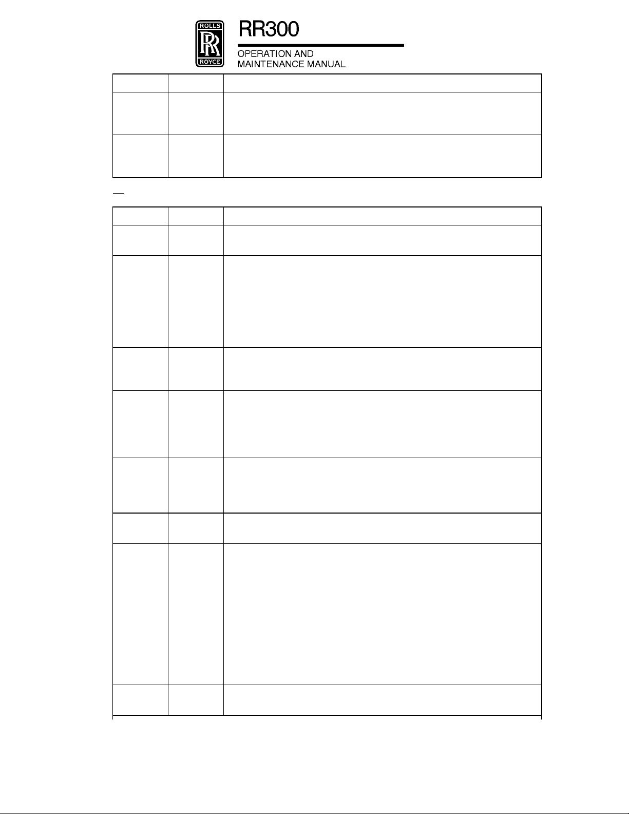
TRANSMITTAL LETTER No.6
Remove: Incorporate: Reason For Change:
CHAPTER 05
List of Effective Pages Page 1/2 Page 1/2
05-50-00-100-801 All Pages Pages 701 and 702 Revised - Changed
internal and external flush
task sequence numbers WP191890
CHAPTER 72
List of Effective Pages Pages 1 to 3/4 Pages 1 to 3/4
72-00-00-100-803 All Pages Pages 701 to 703/704 Deleted tasks for external
rinse - WP191891
72-30-00-200-801 All Pages Pages 601 to 605/606 Revised - Revised
illsutration, FIG. 602 to
match RR300 part WP195413
72-30-00-300-801 All Pages Pages 801 to 803/804 Revised - Revised
illustration, FIG. 801 to
match RR300 part WP209753
72-30-05-200-801 All Pages Pages 601 to 603/604 Note added & illustration
modified - WP207805
72-40-50-300-801 All Pages Page 801/802 Revised - Task Deleted,
cannot repair dents in
combustion liner assembly
at OMM level - WP
217855.
72-60-10-000-805 All Pages Pages 401 to 404 Revision - Change to add
new removal tool
23083912 - WP215606
Page 3

Remove: Incorporate: Reason For Change:
PROPRIETARY DATA - UNSECURED DATA
PROPRIETARY DATA - UNSECURED COPY
PROPRIETARY DATA - UNSECURED COPY
PROPRIETARY DATA - UNSECURED COPY
72-60-10-400-805 All Pages Pages 401 to 406 Revision - Change to add
new installation tool
23083918 - WP215607
CHAPTER 73
List of Effective Pages Pages 1 and 2 Pages 1 and 2
CONTENTS Pages 1 and 2 Pages 1 to 3/4
73-11-10-700-801 Pages 501 to 503/504 First Issue - Test the fuel
nozzle - WP 209769
73-11-10-200-801 All Pages Pages 601 to 603/604 Revised - Added
instructions to inspection
table to clean the fuel
nozzle - WP 209768
73-11-10-100-801 Pages 701 to 705/706 First Issue - Clean the fuel
nozzle without
disassembly - WP 209767
CHAPTER 79
List of Effective Pages Page 1/2 Page 1/2
79-23-10-400-801 All Pages Pages 401 to 404 Revised - Oil change
process to add bleeding of
the #1 and 8 scavenge
lines along with bleeding
of the filter bowl WP191608
79-33-10-700-801 All Pages Pages 501 to 503/504 Revised - WP120364 :
Added tooling and
changed nomenclature of
part - WP120364
79-33-15-700-801 All Pages Pages 501 to 503/504 Revised - WP120366 :
Changed part
nomenclature - WP120366
Record of Revisions Sheet Record incorporation
of TL 6 and date of
incorporation on
RECORD OF
CERTIFIED
REVISIONS
2
Page 4

EXPORT CONTROLLED
PROPRIETARY DATA - UNSECURED DATA
PROPRIETARY DATA - UNSECURED COPY
PROPRIETARY DATA - UNSECURED COPY
PROPRIETARY DATA - UNSECURED COPY
EFFECTIVITY: ALL
SERVICE BULLETIN LIST
© COPYRIGHT 2008, 2012 Rolls-Royce Corporation (unpublished)
Page 1/2
Jan 20/08
Page 5

EXPORT CONTROLLED
PROPRIETARY DATA - UNSECURED DATA
PROPRIETARY DATA - UNSECURED COPY
PROPRIETARY DATA - UNSECURED COPY
PROPRIETARY DATA - UNSECURED COPY
INTRODUCTION
A. General
(1) Operation and Maintenance Manual
(a) The engine model designation used throughout this manual (RR300 Series) refers to the same
engine model (250-C300/A1) that is both stamped on the engine data plate and listed on the
official Engine Type Certificate, Number E4CE, issued by the FAA. The RR300 Series
Operation and Maintenance Manual (OMM) is part of a set of manuals that helps the operator
do the necessary maintenance to the engine. It is written so a technician who does not know
the engine can:
- Do the maintenance and the servicing of the engine systems and components
- Isolate failures of the engine systems and components.
- Use the OMM when the engine is installed on the aircraft.
(b) Rolls-Royce technical publications, in whole or in part, cannot be utilized as a means to
establish serviceability of material not manufactured or approved by Rolls-Royce. Rolls-Royce
technical publications and documents are developed solely for use in support of applicable
Rolls-Royce parts. Parts, materials, or processes not approved by Rolls-Royce were not
considered in the development of Rolls-Royce technical publications due to Rolls-Royce not
having knowledge of any specifications or design criteria for parts, overhaul or repair processes
of parts or material not authorized by Rolls-Royce. Therefore, Rolls-Royce technical
publications must not be used to support or maintain engines, modules, or parts using details,
parts, materials, or processes that are not Rolls-Royce approved. Rolls-Royce disclaims any
liability for the performance or the failure to perform of engines, modules or parts that have
been maintained or supported using parts, materials, or processes not authorized by
Rolls-Royce.
(2) Related Manuals
(a) The manuals included in the set are the:
- Operation and Maintenance Manual (OMM)
- Line Level Illustrated Parts Catalog (LLIPC).
B. Potential Safety Issues
(1) When performing maintenance on RR300 Series engines, the approved maintenance facilities are
responsible for reporting safety related items. Safety related items must be reported to Rolls-Royce
Customer Service (REF. Section L.) and the Federal Aviation Administration. Refer to FAR 145.221
Service Difficulty Reports.
C. The Specifications of this Manual
(1) This manual is written to the Air Transport Association of America Specification No. 100 (ATA 100),
Revision 31. The writing rules and the vocabulary are in accordance with the ASD Simplified
Technical English, Specification ASD-STE-100, Issue 3. All the spelling is in American English.
D. Manual Content
(1) Manual Frontmatter.
EFFECTIVITY: ALL
INTRODUCTION
© COPYRIGHT 2008, 2012 Rolls-Royce Corporation (unpublished)
Page 1
Dec 15/11
Page 6
EXPORT CONTROLLED
PROPRIETARY DATA - UNSECURED DATA
PROPRIETARY DATA - UNSECURED COPY
PROPRIETARY DATA - UNSECURED COPY
PROPRIETARY DATA - UNSECURED COPY
(a) The OMM contains a set of manual frontmatter and a set of chapters. The manual frontmatter
includes:
- The Title page
- The Record of Revisions
- The Frontmatter List of Effective Pages
- The Table of Contents
- The List of Service Bulletins
- The Introduction.
(2) The Chapter Number System.
(a) The OMM has these groups of chapters:
1 General
- Chapter 05 - Time Limits/Maintenance checks
- Chapter 12 - Engine Servicing
- Chapter 70 - Standard Practices - Engine
2
Power Plant
- Chapter 71 - Power Plant
- Section 1 - Engine Description
- Section 2 - Engine Performance and Operation
3 Engine
- Chapter 72 - Engine
- Chapter 73 - Engine Fuel and Control
- Chapter 74 - Ignition
- Chapter 75 - Air
- Chapter 77 - Engine Indicating
- Chapter 79 - Oil
- Chapter 80 - Starting.
(3) Tab Dividers.
(a) At the front of each chapter there is a yellow tab card. The chapter number and title are printed
on the tab. There is also a yellow tab card at the front of the Introduction.
(4) Identification Code.
(a) An identification code that has six numbers divides the chapter into its related parts. This
identification code is divided into three elements. Each element contains two numbers. The
code divides the data into:
- Chapter/System (First element)
- Section/Sub-system (Second element)
- Subject/Unit (Third element).
(5) The List of Temporary Revisions.
(a) The List of Temporary Revisions (LETR) lets the operator make a record of the Temporary
Revisions (TRs) that affect each Chapter.
(6) The Page Number System.
EFFECTIVITY: ALL
© COPYRIGHT 2008, 2012 Rolls-Royce Corporation (unpublished)
INTRODUCTION
Page 2
Dec 15/11
Page 7

EXPORT CONTROLLED
PROPRIETARY DATA - UNSECURED DATA
PROPRIETARY DATA - UNSECURED COPY
PROPRIETARY DATA - UNSECURED COPY
PROPRIETARY DATA - UNSECURED COPY
(a) A system of page numbers divides each Chapter-Section-Subject (CH-SE-SU) into page
blocks and topics, as follows:
- Page Block 1 - Description and Operation
- Page Block 101 - Fault Isolation
- Page Block 201 - Maintenance Practices
- Page Block 301 - Servicing
- Page Block 401 - Removal/Installation
- Page Block 501 - Adjustment/Test
- Page Block 601 - Inspection/Check
- Page Block 701 - Cleaning/Painting
- Page Block 801 - Repairs.
(b) The page identification code, which includes the CH-SE-SU code, is given at the bottom right
side of each page.
(7) The Chapter List of Effective Pages (LEP).
(a) The LEP of a chapter gives a list, in page block sequence, of pages contained in the chapter.
The LEP includes a list of the Contents and the LEP pages.
(b) The data adjacent to each page number on the LEP shows the correct revision date for that
page. The number of pages contained in a chapter and the data on each page must agree with
the LEP data.
(c) Each time a chapter has a revision, a new LEP is issued to give the new revision date of the
changed pages.
(8) The Chapter Contents Pages.
(a) The chapter contents pages gives a list, in CH-SE-SU number sequence, of the subjects
included in a chapter. The topics for each subject are shown in page block sequence.
(9) The Figure Number System.
(a) The figure number system in a page block is the same as the page number system. For
example, the second figure in a Maintenance Practices page block is FIG. 202. The figures for
each task are at the end of the task.
(10) Data in this Manual.
(a) The data in this manual includes:
- The data necessary to do the scheduled maintenance tasks
- The data that describes the engine, its structure and systems, and tells how the systems
operate
- The procedures and related safety precautions for on-wing servicing and maintenance
necessary for continued airworthiness.
E. Page Block and Topic Contents
(1) Page Block 1 - Description and Operation.
(a) This topic gives sufficient data to train maintenance persons to know the function, the
configuration, the operation and the control of the system or component.
(2) Page Block 101 - Fault Isolation.
(a) This topic gives the procedures to isolate and correct faults in a system or component.
(3) Page Block 201 - Maintenance Practices.
(a) This topic includes all maintenance procedures, applicable to a CH-SE-SU, easily contained in
one page block. Page Block 201 is also for those maintenance procedures that are not related
to the topics of other page blocks.
EFFECTIVITY: ALL
INTRODUCTION
© COPYRIGHT 2008, 2012 Rolls-Royce Corporation (unpublished)
Page 3
Dec 15/11
Page 8

EXPORT CONTROLLED
PROPRIETARY DATA - UNSECURED DATA
PROPRIETARY DATA - UNSECURED COPY
PROPRIETARY DATA - UNSECURED COPY
PROPRIETARY DATA - UNSECURED COPY
(4) Page Block 301 - Servicing.
(a) This page block contains the applicable data for the scheduled and the unscheduled servicing.
(5) Page Block 401 - Removal/Installation.
(a) This topic gives the data necessary for the removal and installation of a unit/assembly.
(6) Page Block 501 - Adjustment/Test.
(a) This topic gives the data necessary to adjust and/or do a test of a system, sub-system,
assembly, or unit. There are two types of tests:
1 The Operational Test is the procedure to make sure that a system, sub-system, assembly,
or unit operates. Special equipment is not necessary for this test.
2 The Functional Test is the procedure to make sure that a system, subsystem, assembly,
or unit is correctly adjusted and operates fully to its specification. The test usually uses
special equipment to measure the performance of the system, sub-system, assembly, or
unit.
(7) Page Block 601 - Inspection/Check.
(a) This topic gives the data necessary to make sure that a system, sub-system, assembly, unit, or
part is serviceable.
1
Inspection Tables tables are divided into four categories.
a The first category is ITEM. The ITEM category contains the engine component, or
sub-assembly of that component. The type of damage or condition of the part or
sub-assembly is directly under the part nomenclature and is hyphenated.
b The second category is the SERVICEABLE LIMIT. The SERVICEABLE LIMIT is
defined as the maximum degree of a specified condition which can be accepted and
lets the part be placed back into service without repair. No other action is necessary.
c The third category is the REPAIR LIMIT. The REPAIR LIMIT is defined as the
maximum degree of a specified condition which can be repaired. Any condition
exceeding this limit cannot be corrected by the specified repair procedure; therefore,
the part must be replaced.
d The fourth category is ACTION NECESSARY. The ACTION NECESSARY is defined
as the recommended corrective action for a given condition.
(8) Page Block 701 - Cleaning/Painting.
(a) This topic gives the data necessary to clean and/or paint parts or areas of the engine.
(9) Page Block 801 - Repairs.
(a) This topic gives repair procedures that are necessary during on-wing maintenance and are not
included in another manual.
F. Effectivity
(1) The EFFECTIVITY Block.
(a) The effectivity block is located in the lower left corner of the page. The effectivity block
identifies engine model, maintenance data, or other maintenance information that applies to the
configuration of the engine. The data must be considered satisfactory for all of the engine
models when the effectivity block has been removed or is blank.
G. How to Use this Manual
(1) The Applicable Data.
EFFECTIVITY: ALL
© COPYRIGHT 2008, 2012 Rolls-Royce Corporation (unpublished)
INTRODUCTION
Page 4
Dec 15/11
Page 9

EXPORT CONTROLLED
PROPRIETARY DATA - UNSECURED DATA
PROPRIETARY DATA - UNSECURED COPY
PROPRIETARY DATA - UNSECURED COPY
PROPRIETARY DATA - UNSECURED COPY
(a) To find the data applicable to your task:
1 Refer to the list of chapters in para D. (2)(a) of this Introduction and find the chapter
related to the necessary data.
2 Read the yellow tab cards to identify the necessary chapter.
3 Open the manual at the start of the applicable chapter and refer to the contents pages.
NOTE: The contents page of each chapter gives a list of the data/procedures in the
related chapter. The list is in CH-SE-SU sequence. The page blocks of each
CH-SE-SU are in number sequence.
4 Identify the CH-SE-SU on the contents page.
5 Identify the page block applicable to the necessary data (Refer to para D. (6) of this
Introduction for a list of the page block numbers and their titles).
6 An example of the procedure given in the above para G. (1)(a) of this Introduction is as
follows:
a
To find the data to remove and install a fuel nozzle, you must:
- Identify that the item is part of the fuel system.
- Refer to the List of Chapters in para D. (2)(a)2 Power Plant.
- Identify Chapter 73 - Engine Fuel and Control.
- Use the yellow tab cards in the manual to find Chapter 73 - Engine Fuel and
Control.
- Refer to the Contents at the start of Chapter 73 and identify the necessary data,
which is 73-11-10, Page Block 401 - Fuel Nozzle Removal/Installation.
- Open the manual at 73-11-10, Page Block 401, where you will find the necessary
procedures to remove and install the fuel nozzle.
(2) Aircraft Maintenance Task Oriented Support System (AMTOSS).
(a) AMTOSS Codes.REF. FIG. 1
1 AMTOSS codes are included in page blocks 201 thru 801. AMTOSS gives each of the
maintenance procedures (tasks) and the primary steps of the procedures (subtasks) a
different number identification code.
2 The identification code numbers have a minimum of five elements and a maximum of
seven elements. These elements are an extension of the three-element ATA 100
CH-SE-SU numbers. Refer to FIG. 1 for an example of task and subtask code.
(b) Function Codes.
1 The function codes in the AMTOSS task (T) and subtask (S) numbers show the type of
work that has to be done. The function codes used and a description of each is in the list
that follows:
2 Function code 000 - Removal.
APPL FC APPLICATION OF THE FUNCTION CODES
T 000 REMOVAL
EFFECTIVITY: ALL
The subtask content of the removal task must mirror that of its
associated installation task. In particular, the 400 function codes
used must bear a direct relation to the 000 codes. This number is
only used for a task title line, i.e., Remove the Fuel Nozzle.
INTRODUCTION
© COPYRIGHT 2008, 2012 Rolls-Royce Corporation (unpublished)
Page 5
Dec 15/11
Page 10

EXPORT CONTROLLED
PROPRIETARY DATA - UNSECURED DATA
PROPRIETARY DATA - UNSECURED COPY
PROPRIETARY DATA - UNSECURED COPY
PROPRIETARY DATA - UNSECURED COPY
APPL FC APPLICATION OF THE FUNCTION CODES
T/S 010 REMOVE/OPEN FOR ACCESS
S 020 REMOVE UNIT/COMPONENT/or any part of the UNIT Removal of
T/S 040 DEACTIVATE
S 080 REMOVE TEST/SUPPORT EQUIPMENT
Remove or open a panel, door, component, etc. to gain access to
the task subject or to allow the core subtask to be done. Includes
removal/disconnection of items that impede access but are not
related to the task subject.
the Unit (the ATA breakdown subject) including all attaching and
connected parts. This can also include capping of lines, electrical
connectors, etc.
Deactivation of the system. Covers making a system component etc.
inoperable for maintenance by means other than circuit breaker,
blocking tools, etc., which are covered by specific codes.
Remove or disconnect any tool that has been defined as special or
standard and that is not covered by function codes 941/942.
3 Function code 100 - Cleaning.
APPL FC APPLICATION OF THE FUNCTION CODES
T 100 CLEANING
This is not to be used for preparation for another task. This number
is only used in a task title line.
T/S 110 CHEMICAL
Use chemical agent(s) to clean. Includes preparation of the
chemical.
T/S 120 ABRASIVE
Remove unwanted materials with WET/DRY particle impingement.
T/S 130 ULTRASONIC (SOUND WAVES)
Remove unwanted surface material and other materials caught in
the surface using high-frequency sound.
T/S 140 MECHANICAL
Remove unwanted materials with a brush, lint-free cloth or other
mechanical procedure.
T/S 150 STRIPPING
Removal of paint, etc. from metal or non-metal surfaces using
mechanical or chemical process. Also includes the removal of any
residue from the process.
T/S 160 MISCELLANEOUS CLEANING
T/S 170 FLUSHING
EFFECTIVITY: ALL
© COPYRIGHT 2008, 2012 Rolls-Royce Corporation (unpublished)
Remove unwanted material with compressed air, suction, by hand,
etc.
Flush unwanted material through and out of a component or system
with fluid.
INTRODUCTION
Page 6
Dec 15/11
Page 11

EXPORT CONTROLLED
PROPRIETARY DATA - UNSECURED DATA
PROPRIETARY DATA - UNSECURED COPY
PROPRIETARY DATA - UNSECURED COPY
PROPRIETARY DATA - UNSECURED COPY
4 Function code 200 - Inspection/Check.
APPL
T 200 INSPECTION/CHECK
T/S 210 GENERAL VISUAL
T/S 220 DETAILED DIMENSIONAL
T/S 230 PENETRANT
T/S 240 MAGNETIC
T/S 250 EDDY CURRENT
FC APPLICATION OF THE FUNCTION CODES
This number is only used in a task title line, i.e. Inspect the
Desiccator Crystals.
Full inspection of
ZONE/SYSTEM/SUBSYSTEM/COMPONENT/PART to find
structural damage, failure, and/or deterioration. Gives the proper
corrective maintenance procedure if necessary. Not to be used for
FOD checks, during job close-up, etc.
Inspect dimensions, conditions, or indications of
COMPONENTS/SUBSYSTEMS/SYSTEMS. Compare with
specifications in the original design documentation to decide
whether further maintenance is required.
Include checks of indicators and other readouts to confirm that a
value is within limits.
Find surface cracks with dye penetrant techniques.
Find surface cracks in a material by means of magnetic fields.
Use electromagnetic waves to find internal cracks, porosity, very
small openings, unwanted materials, or non-homogeneous material
structure.
T/S 260 X-RAY/HOLOGRAPHIC
To find internal cracks, porosity, very small openings, unwanted
materials, or non-homogeneous material structure.
T/S 270 ULTRASONIC
To find internal cracks, porosity, very small openings, unwanted
materials, or non-homogeneous material structure.
T/S 280 SPECIFIC/SPECIAL
For procedures NOT INCLUDED in codes 210-270 and 290.
Includes abnormal operation and continued service procedures.
T/S 281 SAMPLING
Procedures to obtain small representative quantities of materials
(gas, liquid, or solid) for the purpose of analysis.
T/S 290 BORESCOPE
To do an internal examination of a component, part and/or
assembly.
EFFECTIVITY: ALL
INTRODUCTION
© COPYRIGHT 2008, 2012 Rolls-Royce Corporation (unpublished)
Page 7
Dec 15/11
Page 12

EXPORT CONTROLLED
PROPRIETARY DATA - UNSECURED DATA
PROPRIETARY DATA - UNSECURED COPY
PROPRIETARY DATA - UNSECURED COPY
PROPRIETARY DATA - UNSECURED COPY
5 Function code 300 - Repair.
APPL
T 300 REPAIR
T/S 310 WELDING/BRAZING
T/S 320 MACHINING/RENAMING/BLENDING
T/S 330 COMPOSITE
T/S 340 FIBERGLASS/PLASTIC/HONEYCOMB/EPOXY
T/S 350 MISCELLANEOUS REPAIR
T/S 360 LEAKAGE REPAIR Repair leaks (except by application of
T/S 370 PAINTING
FC APPLICATION OF THE FUNCTION CODES
This number is only used in a task title line.
Join parts together by any welding or brazing method.
Repair metal parts or assemblies.
Repair composite materials.
Repair fiberglass, plastic, honeycomb or epoxy materials. Also
includes adhesive bonding, rubber molding, fiberglass molding,
silicone rubber bonding/molding, etc.
Repair those materials or parts not included above.
sealants/compounds -see code 390).
Application of primer and top coat to any area. Includes surface
pre-treatment and cleaning, mixing, application, and curing.
T/S 380 SPECIAL
For procedures NOT INCLUDED in codes 210-270 and 290.
Includes abnormal operation and continued service procedures.
T/S 390 SEALING
Apply fairing compounds, sealants, or other materials to control
corrosion, fill clearance, prevent leakage, provide a hold, or smooth
aerodynamically. Includes preparation of materials, cleaning of
surfaces, mixing and curing.
6 Function code 400 - Installation.
APPL FC APPLICATION OF THE FUNCTION CODES
T 400 INSTALLATION
This number is only used in a task title line, i.e. Install the Fuel
Nozzle.
T/S 410 INSTALL/CLOSE FOR ACCESS
Install or close a panel, door, component, etc. used to gain access to
the task subject or to allow the core subtask to be done. Includes
installation/re-connection of items that impeded access but are not
related to the task subject.
T/S 420 INSTALL UNIT/COMPONENT Installation of the Unit (the ATA
breakdown subject) includes all attaching and connected parts. This
is the core Subtask of an installation task for the complete ATA
subject number unit.
EFFECTIVITY: ALL
© COPYRIGHT 2008, 2012 Rolls-Royce Corporation (unpublished)
INTRODUCTION
Page 8
Dec 15/11
Page 13

EXPORT CONTROLLED
PROPRIETARY DATA - UNSECURED DATA
PROPRIETARY DATA - UNSECURED COPY
PROPRIETARY DATA - UNSECURED COPY
PROPRIETARY DATA - UNSECURED COPY
APPL FC APPLICATION OF THE FUNCTION CODES
T/S 440 DEACTIVATE
T/S 480 INSTALL TEST/SUPPORT EQUIPMENT
7 Function code 500 - Material Handling.
APPL FC APPLICATION OF THE FUNCTION CODES
Deactivation of a system. Covers making a system component, etc.
operable after maintenance by means other than circuit breakers,
blocking tools, etc., which are covered by specific codes.
Install or connect any tool that has been defined as special or
standard, and the purpose of which is to show or simulate the
condition, position, status, etc. of a system component. Does NOT
include test equipment installed as an integral part of the core
subtask unless the installation is sufficiently complex to warrant a
separate subtask. Includes items that are not physically connected
to the aircraft, such as a radio test transmitter. Also includes rigging
pins, etc. installed for purposes other than rigging the system in
which they are fitted (see code 941).
T 500 MATERIAL HANDLING
This number is only used in a task title line.
T/S 530 PACKING
Packing consists of installation of parts, sub-assemblies, or
assemblies in shipping containers. This includes all capping of lines,
installation of plugs, etc. Applicable to prepare a component after
removal from aircraft for storage.
T/S 540 UNPACKING
Unpacking is defined as the removal of items, sub-assemblies, or
assemblies from shipping containers. This includes all removal of all
protection material. The component that is the subject of an
installation task is to be considered as unpacked, depreserved, etc.
T/S 550 STORAGE/RETURN TO SERVICE
Storage is the safekeeping of the aircraft/engine and
assemblies/sub-assemblies until required for use. Can require
specific procedures not covered by any other function codes. Return
to service is the specific procedure to prepare for operation.
S 560 MARSHALLING
Marshalling refers to the collecting of individual parts,
sub-assemblies, or assemblies prior to release for assembly. This
function code must be used for replacement component preparation
before installation. One subtask must cover the complete
preparation procedure.
T 580 AIRCRAFT HANDLING
T/S 581 LIFTING
EFFECTIVITY: ALL
See breakdown below.
ATA Chapter 7.
INTRODUCTION
© COPYRIGHT 2008, 2012 Rolls-Royce Corporation (unpublished)
Page 9
Dec 15/11
Page 14

EXPORT CONTROLLED
PROPRIETARY DATA - UNSECURED DATA
PROPRIETARY DATA - UNSECURED COPY
PROPRIETARY DATA - UNSECURED COPY
PROPRIETARY DATA - UNSECURED COPY
APPL FC APPLICATION OF THE FUNCTION CODES
T/S 582 JACKING
T/S 583 SHORING
T/S 584 TOWING
T/S 585 TAXIING
T/S 586 LEVELING AND WEIGHING
8 Function code 600 - Servicing/Preserving/Lubrication.
APPL FC APPLICATION OF THE FUNCTION CODES
T 600 SERVICING/PRESERVING/LUBRICATION
ATA Chapter 7.
Includes lifting and lowering the jacks.
ATA Chapter 7.
ATA Chapter 9.
ATA Chapter 9.
ATA Chapter 8.
This number is only used in a task title line.
T/S 610 SERVICING
To keep in good operational condition, including procedures not
specified by other breakdowns in this series. Includes replenishing
(filling) of fluids (oil, hydraulic, water, etc.).
T/S 614 GAS CHARGING/DISCHARGING
Tires, accumulators, etc.
T/S 620 PRESERVING
This is the preparation of a component/part for safekeeping from
decomposition or deterioration. Includes preparation for storage by
applying a preservative layer to, and desiccants in, hardware. It also
includes the prevention of microbial growth in fuel tanks, application
of corrosion inhibitants and protection, etc. Does not include aircraft
storage, which is covered by Function Code 550.
T/S 630 DEPRESERVING
Depreserving pertains to removing the preservative layer and/or
desiccants form the component/part in preparation for installation or
operation.
T/S 640 LUBRICATING
ONLY for PURE lubrication tasks and subtasks. Lubricate moving
parts.
T/S 650 FUELING/DEFUELING
Fuel movement for all operational and maintenance purposes.
T/S 660 DEICING/ANTI-ICING
EFFECTIVITY: ALL
© COPYRIGHT 2008, 2012 Rolls-Royce Corporation (unpublished)
Removal and prevention of ice and snow build-up on parked aircraft
and applications to prevent the accumulation of ice and snow.
INTRODUCTION
Page 10
Dec 15/11
Page 15

EXPORT CONTROLLED
PROPRIETARY DATA - UNSECURED DATA
PROPRIETARY DATA - UNSECURED COPY
PROPRIETARY DATA - UNSECURED COPY
PROPRIETARY DATA - UNSECURED COPY
APPL FC APPLICATION OF THE FUNCTION CODES
T/S 670 DISINFECT/SANITIZE
T/S 680 DRAIN FLUID
9 Function code 700 - Testing.
APPL FC APPLICATION OF THE FUNCTION CODES
T 700 TESTING
T/S 710 OPERATIONAL
Core subtask for health conditions. Can include draining (where
integral to the task), cleaning and handling of lavatory components,
etc.
During servicing or other maintenance procedures, such as water,
oil, fuel, lavatories, etc. This is the other half of replenishing when
the system is to be emptied and filled.
This number is only used in a task title line.
An operational test verifies that the system or component is
operable, without taking into account specifications and tolerances
that are usually established for overhaul or major maintenance
periods. The test requires no special equipment. Can include BITE
functions.
T/S 720 FUNCTIONAL
A functional test verifies that a system or component is functioning
within the minimum design specifications. This test is more detailed
than an operational test and can require special test equipment.
Values and tolerances must be specified. Can include BITE
functions.
T/S 730 SYSTEM
Contains all specifications and tolerances necessary to make sure
the system and its components are performing at maximum design
efficiency. The test must be sufficiently thorough to detect early
signs of wear, deterioration, and calibration drift. The test can
require special test equipment. Values and tolerances must be
specified. The test is self-contained and can duplicate another test.
Can include BITE functions.
T/S 740 BITE
Used for tasks (and subtasks where the test is part of a task
procedure). Those checks conducted using Built-In Test Equipment
(BITE) and Maintenance Diagnostic System (MDS) including the
power-up test.
T/S 750 SPECIAL
Used for tasks (and subtasks where the test is part of a
taskprocedure). Special checks such as smoke check, sniff checks,
etc.
T/S 760 ELECTRICAL
EFFECTIVITY: ALL
Electrical checks to determine continuity, voltage, resistance, etc.
INTRODUCTION
© COPYRIGHT 2008, 2012 Rolls-Royce Corporation (unpublished)
Page 11
Dec 15/11
Page 16
EXPORT CONTROLLED
PROPRIETARY DATA - UNSECURED DATA
PROPRIETARY DATA - UNSECURED COPY
PROPRIETARY DATA - UNSECURED COPY
PROPRIETARY DATA - UNSECURED COPY
APPL FC APPLICATION OF THE FUNCTION CODES
T/S 780 PRESSURE
T/S 790 LEAK
10 Function code 800 - Miscellaneous.
APPL FC APPLICATION OF THE FUNCTION CODES
T 800 MISCELLANEOUS
T/S 810 FAULT ISOLATION
Establishes the ability of a normally pressurized system or
component to operate properly.
Make sure a system or component does not leak or does so within
specified limits. Procedures for application of leak check solutions.
This number is only used in a task title line.
Fault isolation consists of the following procedures:
- Operating the engine to locate the prime suspect deficient system
- Operating an improperly functioning system or component in order
to locate the cause of the malfunction
- Performing a series of prescribed checks to isolate a failed part or
component.
T/S 820 ADJUSTING/ALIGNING/CALIBRATING
Make a physical correction to ensure proper placement,
operation or testing of a system or component.
T/S 830 RIGGING
Check, and, as necessary, adjust mechanically operated systems
such as flight control cables, actuator arms, push-pullrods, etc.
Includes installing and removing rigging pins, blocks, boards, etc.
where specifically used to give an indication of the state of rigging.
T/S 840 PREPARE FOR . . ., RESTORE . . ., TO NORMAL . . .
Used when separate tasks are provided for preparing for
maintenance or restoring to normal after maintenance when these
procedures are lengthy and identical for several applications.
T/S 850 OPERATOR MODIFICATION INCORPORATION
Operator use only. Complete tasks only.
T/S 860 AIRCRAFT/SYSTEM CONFIGURATION
Make sure the aircraft is in an approved condition for maintenance
or to return it to an operational configuration. This code also covers
operating any system or component in order to accomplish a task.
Also specifically covers the following operations:
- Energize electrical network
- De-energize electrical network
- Pressurize hydraulics
- De-pressurize hydraulics
- Circuit breaker opening
- Circuit breaker closing.
T/S 870 BLEEDING
EFFECTIVITY: ALL
© COPYRIGHT 2008, 2012 Rolls-Royce Corporation (unpublished)
Remove air from a system or unit filled with fluid.
INTRODUCTION
Page 12
Dec 15/11
Page 17

EXPORT CONTROLLED
PROPRIETARY DATA - UNSECURED DATA
PROPRIETARY DATA - UNSECURED COPY
PROPRIETARY DATA - UNSECURED COPY
PROPRIETARY DATA - UNSECURED COPY
APPL FC APPLICATION OF THE FUNCTION CODES
T/S 880 HEATING/COOLING
11 Function code 900 - Change = Removal + Installation.
APPL FC APPLICATION OF THE FUNCTION CODES
T 900 CHANGE = REMOVAL + INSTALLATION
T/S 910 STANDARD PRACTICES
T/S 930 PAINT MARKING
T 940 JOB SET-UP/CLOSE-UP
Application of heating or cooling required for removal, installation,
adjustment, or testing.
This code links the removal and installation procedures of a
component or item.
Refer out of normal tasks to this code. Task can only be located in
Chapter 20, 51, and 70.
To paint markings and letters.
See breakdown below.
S 941 JOB SET-UP
Covers the positioning of general support equipment NOT covered
by the codes 480/080. Specifically: access platforms, steps, warning
notices, and fire extinguishers.
S 942 JOB CLOSE-UP
Covers the removal of general support equipment NOT covered by
the codes 480/080. Specifically: access platforms, steps, warning
notices, and fire extinguishers.
S 950 MASKING
Masking or unmasking required for painting, cleaning,
surfaceprotections, etc.
T/S 960 REPLACE
The removal and installation of minor components (O-rings, etc.)
when completely covered within one subtask. Normally only for
limited use within servicing tasks.
S 965 TRANSFER PARTS
To be used for the transfer of parts from the removed component to
the installed component.
S 970 DATA RECORDING/CALCULATING
Recording of data required for monitoring, testing, adjusting,
checking, etc., and subsequent calculation.
S 980 MANUAL OPERATION OR POSITIONING
Manually positioning or operating a system component or unit that is
normally powered, such as turning engine rotor manually, translating
thrust reversers, etc.
S 990 ILLUSTRATIONS
EFFECTIVITY: ALL
To be used when creating illustration tasks only.
INTRODUCTION
© COPYRIGHT 2008, 2012 Rolls-Royce Corporation (unpublished)
Page 13
Dec 15/11
Page 18
EXPORT CONTROLLED
PROPRIETARY DATA - UNSECURED DATA
PROPRIETARY DATA - UNSECURED COPY
PROPRIETARY DATA - UNSECURED COPY
PROPRIETARY DATA - UNSECURED COPY
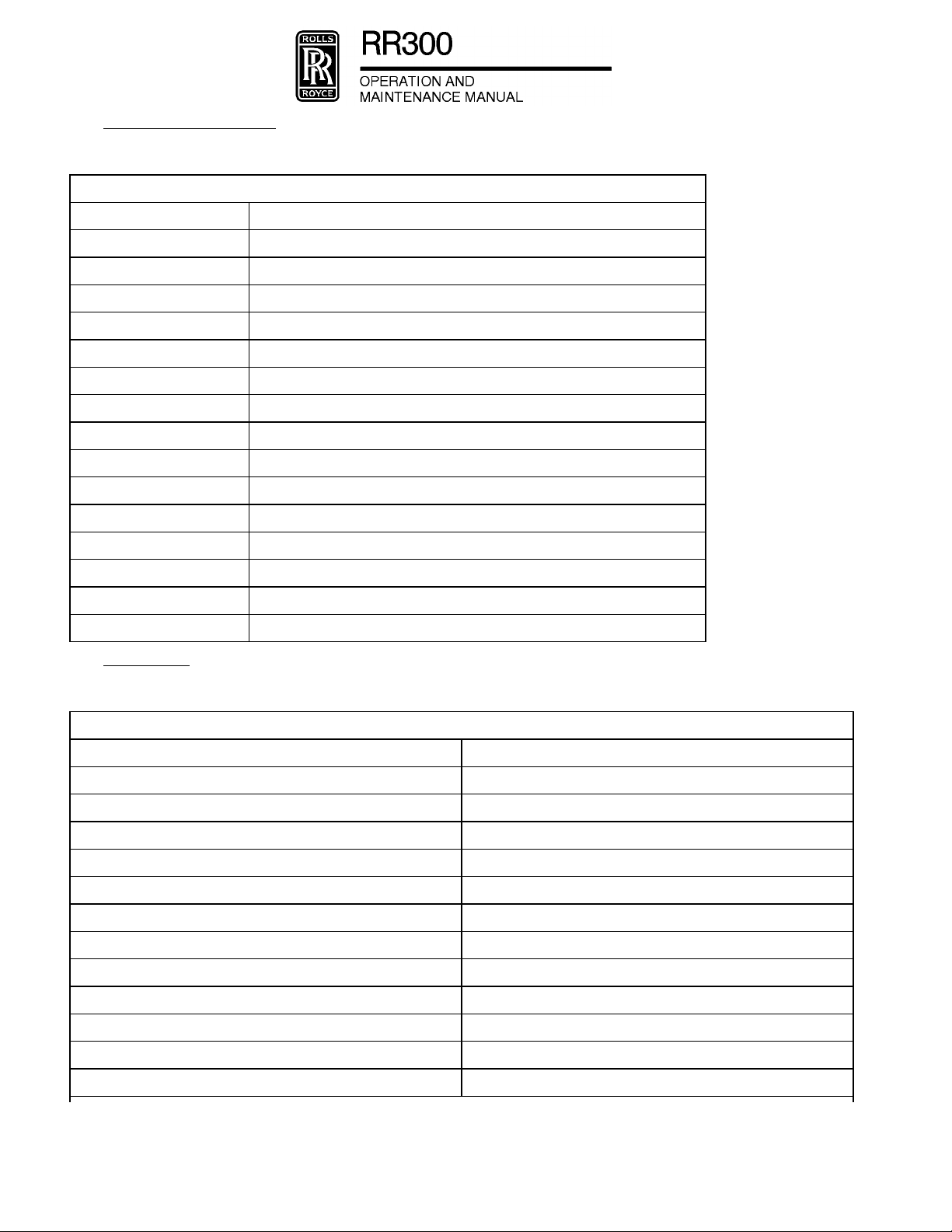
H. Abbreviations and Terms
(1) The following terms and abbreviations will be used in this manual.
ABBREVIATIONS AND TERMS
TERM DEFINITION
AGB Accessory Gearbox
GI Ground Idle
GPT Gas Producer Turbine
ID Inside Diameter
IGN Ignition
ISA International Standard Atmosphere
MGT Measured Gas Temperature
LP Low Pressure
MCT Maximum Continuous
MTO Maximum Takeoff
OD Outside Diameter
PT Power Turbine
RMS Root Mean Square
RPM Revolutions per Minute
Wf Engine Fuel Flow Rate
I. Conversions
(1) The following conversion factors will be used in this manual.
CONVERSIONS
U.S. Metric
1 in. (inch) 25.4 mm (millimeters)
1 in.² (square inch) 6.4516 cm² (square centimeters)
1 ips (inch per second) 2.54 cm/s (centimeters per second)
1 SFM (surface foot per minute) 0.3048 SMM (surface meters per minute)
°F (degrees Fahrenheit) 9/5 (°C) + 32 (°C = degrees Celsius)
1 US gal (US gallon) 3.785 liters
1 US gal (US gallon) 0.8326 Imperial gallons
1 psi (pound per square inch) 6894.757 Pa (Pascals)
1 psi (pound per square inch) 6.894757 kPa (kiloPascals)
1 psi (pound per square inch) 6894.757 N/m² (Newtons per square meter)
1 inHg (inch of mercury at 32 °F (0 °C) 0.03389 bar
1 inHg (inch of mercury at 32 °F (0 °C) 25.40 mmHg (millimeters of mercury)
EFFECTIVITY: ALL
© COPYRIGHT 2008, 2012 Rolls-Royce Corporation (unpublished)
INTRODUCTION
Page 14
Dec 15/11
Page 19

EXPORT CONTROLLED
PROPRIETARY DATA - UNSECURED DATA
PROPRIETARY DATA - UNSECURED COPY
PROPRIETARY DATA - UNSECURED COPY
PROPRIETARY DATA - UNSECURED COPY
CONVERSIONS
U.S. Metric
1 inHg (inch of mercury at 32 °F (0 °C) 0.4912 psi (pounds per square inch)
1 inHg (inch of mercury at 32 °F (0 °C) 3.387 kPa (kiloPascals)
1 ft-lb (pound-foot) 1.35582 Nm (Newton-meters)
1 in-lb (pound-inch) 0.112985 Nm (Newton-meters)
1 lbf (pound force) 4.44822 N (Newtons)
1 tonf (ton force) 8896.44 N (Newtons)
1 lb (pound) 0.45359 kg (kilograms)
1 oz (ounce) 28.3495 g (grams)
1 SCFM (Standard Cubic Foot per Minute) 28.317 SLM (Standard Liters per Minute)
J. Revisions and Service Bulletins
(1) Issue of Revisions.
(a) The manufacturer regularly issues revisions to the maintenance manual to keep it at the correct
standard. The revisions add, remove, and/or change data as necessary. All revisions are by
replacement of pages. You must not use hand-written revisions.
(b) A letter of Transmittal is sent with each revision. The transmittal letter:
- Is the authority to put the revision into the manual
- Gives instructions on how to put the revision into the manual.
(c) You are recommended to keep the transmittal letters at the front of the manual for reference.
(d) Each revision has a specified number and date. Revisions start at No. 1 and continue in
sequence.
(e) A Record of Revisions page is located at the front of the manual. When you put a revision into
the manual, you must write the revision number and its issue date on the Record of Revisions
page.
(f) A vertical block line or an upper case "R" at the left side of a page shows that the data adjacent
to the line has changed. If a black line is aligned with the page number and date, this means
that the data has not changed, but some of the data on the page has moved to or from a
different page.
(2) Temporary Revisions.
(a) When it is necessary to include data in the manual quickly, a Temporary Revision (TR) is
issued. The first page of the TR gives the transmittal instructions. The data/instructions in a TR
replace the equivalent data/instructions in the manual. A TR can also be used to include data
before the subsequent revision.
(b) Each TR is printed on yellow paper. The TR numbers are in sequence and start at - 1 in each
chapter. The chapter number goes in front of the TR number to give each TR an identification
code. For example 72-1, 72-2, 72-3, and so on, 79-1, 79-2, 79-3, and so on.
(c) The data/instructions in a TR are included in a revision (usually, the subsequent revision to the
manual) or a subsequent TR replaces it. When a revision includes the data/instructions of a
TR, the transmittal letter includes an instruction to remove the applicable TR. When a
subsequent TR replaces a TR, the subsequent TR includes an instruction to remove the
applicable TR. You must not remove a TR from the manual unless you get an instruction to do
so in the Transmittal Letter of a revision or on the first page of a subsequent TR.
EFFECTIVITY: ALL
INTRODUCTION
© COPYRIGHT 2008, 2012 Rolls-Royce Corporation (unpublished)
Page 15
Dec 15/11
Page 20

EXPORT CONTROLLED
PROPRIETARY DATA - UNSECURED DATA
PROPRIETARY DATA - UNSECURED COPY
PROPRIETARY DATA - UNSECURED COPY
PROPRIETARY DATA - UNSECURED COPY
(d) In each chapter, immediately after the List of Effective Pages page, is a Record of Temporary
Revisions page. When you put a TR into the manual, you must write the TR number and the
date you put the TR into the manual on the Record of Temporary Revisions. When you remove
a TR from the manual, you must write the date you removed the TR from the manual on the
Record of Temporary Revisions.
(3) Service Bulletins and Service Letters
(a) At the front of this manual, immediately after the Table of Contents, is the Service Bulletin List.
The data given includes the service bulletin (SB) number, title, date, and the date of
incorporation into this manual, if applicable. When applicable, review engine records for
compliance with all mandatory service bulletins, inspections and Airworthiness Directives.
K. Consumable Materials
(1) Non-restricted Consumable Materials. You can use equivalent materials as an alternative to the
materials in these lists. You can get the materials from local suppliers and/or manufacturers.
MATERIALS
Acetone O-A-51
Acid, sulfuric
Alcohol, isobutyl MIL-E-463
Alcohol, isopropyl TT-I-735
Compound, antisieze CP-63
Compound, antisieze NSN-165
Compound, anti-sieze, Lubriplate 130A
Dessicant MIL-D-3464
Dichromate, sodium
Oil, engine AS5780 HPC
Oil, engine MIL-PRF-23699
Oil, lubricating MIL-L-7808
Oil, preservation MIL-L-6081 grade 1010 or
MIL-L-7870A
Perchloroethylene
Sodium bicarbonate O-S-576
SPECIFICATION
Solution, cleaning (Ref. Paragraph K.(2))R
Solvent, dry-cleaning P-D-680
Solvent, Pentatone ECS
Solvent, Stoddard MIL-PRF-680
Spirits, mineral, EMS-6
Trichloroethane MIL-T-81533
Water, distilled
EFFECTIVITY: ALL
© COPYRIGHT 2008, 2012 Rolls-Royce Corporation (unpublished)
INTRODUCTION
Page 16
Dec 15/11
Page 21

EXPORT CONTROLLED
PROPRIETARY DATA - UNSECURED DATA
PROPRIETARY DATA - UNSECURED COPY
PROPRIETARY DATA - UNSECURED COPY
PROPRIETARY DATA - UNSECURED COPY
(2) The Approved Manufacturers column of the table lists a supplier for each item; equivalent products
are permitted. To find if an item is equivalent, the operator and supplier must show proof, not the
manufacture engineer. The consumable materials used to maintain the engine are in the table that
follows:
MATERIAL
Engine Oil Refer to Section
Lubricant Lubriplate 130A Fiske Brothers Refining Co.
Grease ROYCO HF-825 Royal Lubricants Co., Inc.
SPECIFICATION APPROVED MANUFACTURERS USE
12-10-79, Table 1,
Approved Oils.
129 Lockwood
Newark, New Jersey 07105
280 Complex
101 Eisenhower Parkway
Roseland, New Jersey 07068
Sundstrand P/N
718050 or 71850
(recommended)
ASTM No. 5 Oil Sun Oil Co.
Sundstrand Corp.
4751 Harrison Avenue
Rockford, Illinois 61108
1608 Walnut Street
Philadelphia, Pennsylvania 19103
Lubricate bearings, packings, fuel
pump external drive splines and
starter-generator and front spare
accessory drive splines that
require engine oil.
Lubricate accessory splines
(Starter-generator and front spare
accessory drive splines and fuel
pump external drive splines that
require engine oil are not
included).
Seal and bearing installation and
assembly aid.
Fuel pump drive shaft (internal
splines, external splines require
engine oil and are not included).
Lubricate packings in fuel control
air passages.
Alternates to ASTM
No. 5 Oil:
- 45 to 55% fuel
(MIL-C-7024B,
Type II) mixed with
45 to 55% STP oil
treatment.
- MIL-D-6081, Grade
1010 oil.
Lubriplate Aero Fiske Brothers Refining Company
Lubriplate Division
1500 Oakdale Avenue
Toledo, Ohio 43605
Petrolatum Commercial Assembly aid.
Sealer Scot Clad 776 Scotch Clad Coatings Minnesota
Mining and Mfg. Co.
3M Center
St. Paul, Minnesota 55119
Fuel pump and fuel control drive
shafts (Argo Tech/TRW pumps).
Gearbox splitline.
EFFECTIVITY: ALL
INTRODUCTION
© COPYRIGHT 2008, 2012 Rolls-Royce Corporation (unpublished)
Page 17
Dec 15/11
Page 22

EXPORT CONTROLLED
PROPRIETARY DATA - UNSECURED DATA
PROPRIETARY DATA - UNSECURED COPY
PROPRIETARY DATA - UNSECURED COPY
PROPRIETARY DATA - UNSECURED COPY
MATERIAL SPECIFICATION APPROVED MANUFACTURERS USE
Sealer (cont) DC 994 Dow Corning Corp.
South Saginaw Road
Midland, Michigan 48641
RTV 732 or RTV 736 Dow Corning Corp.
South Saginaw Road
Midland, Michigan 48641
RTV 106 General Electric Corp.
Waterford, New York 12188
Devcon F
(aluminum)
Reisweld FE 186 H.B. Fuller Co.
Metal Set A-4 Smooth-on Inc.
Epon 934 Hysol Div. Dexter Corp.
Scotch-Weld 2214 Product of the 3M Company
Devcon Corp.
59 Endicott Street
Danvers, Massachusetts 01923
2400 Kasota Avenue
St. Paul, Minnesota 55102
1000 Valley Road
Gillette, New Jersey 07933
2850 Willow Pass Road
Pittsburgh, California 94565
Adhesives and Sealers Division
2501 Hudson Road
St. Paul, Minnesota 55119
Gearbox splitline.
Compressor case splitline.
Compressor mounting insert
installation.
Hysol EA9432NA,
EA934, EA9394
Epocast 938-A1,
938-A2
Magnobond 6398 Magnolia Plastics Inc.
Loctite 620 or 602 Loctite Corp.
Sealant No. 1372 W Permatex Co. Inc.
Silicone
resin-clear (AMS
3135)
METCOSEAL AP METCO Inc.
Locktite Corp.
705 North Mountain Road
Newington, Connecticut 06111
Huntsman Advanced Materials
10003 Woodloch Forest Drive
The Woodlands, Texas 77380
5547 Peachtree Industrial
Boulevard
Chamblee, Georgia 30341-2296
705 North Mountain Road
Newington, Connecticut 06111
Box 1350
Flagler Court Bldg.
West Palm Beach, Florida 33402
1105 Prospect Avenue
Westbury, Long Island, New York
11590
Installation of labyrinth stationary
seal bearing area.
Assembly-oil bellows seal.
Compressor mount repair.
EFFECTIVITY: ALL
© COPYRIGHT 2008, 2012 Rolls-Royce Corporation (unpublished)
INTRODUCTION
Page 18
Dec 15/11
Page 23

EXPORT CONTROLLED
PROPRIETARY DATA - UNSECURED DATA
PROPRIETARY DATA - UNSECURED COPY
PROPRIETARY DATA - UNSECURED COPY
PROPRIETARY DATA - UNSECURED COPY
MATERIAL SPECIFICATION APPROVED MANUFACTURERS USE
Silicone
resin-clear (AMS
3135) (cont)
Assembly fluid Ultra Chem No. 1 Ultra Chem Inc.
Antiseize
compound
Methylethyl-ketone Commercial General cleaning.
Carbon removal
compound
1-2531 Dow Corning Corp.
South Saginaw Road
Midland, Michigan 48640
1400 N. Walnut Street
Wilmington, Delaware 19899
Never-Seez Nickel
Special (NSN 165)
Bostik
DC 550 FLUID Dow Corning Corp.
CP-63
(MIL-L-25681B)
Gunk Hydroseal
Decarbonizer
(MIL-C-25107)
Emhart Chemical Group
Boston Street
Middleton, Massachusetts 01949
South Saginaw Road
Midland, Michigan 48641
E/M Lubricants Inc.
P.O. Box 2200 Highway 52
N.W. West Lafayette, Indiana
47906
Gunk Laboratories Inc.
630 North Harlem Avenue
Oak Park, Illinois 60302
Compressor mount repair.
Assembly aid.
Hot section external threads (not
used on parts that have contact
with the engine oil system) or
assembly compressor adapter
nut.
External threads protect up to
450°F (232°C).
External threads not exposed to
oil system. Protects to 1400°F
(760°C).
Clean aluminum coated steel
parts.
Cresol base
cleaning
compound
Cleaner Turbine Cleaner No.
Formula No. 3097
(MIL-C-546)
1191 (MIL-C-43616)
20-20 Plus
(MIL-C-43616)
Turbo Clean or
Turbo Clean 2
R-MC ECT, Inc.
Turco Products Inc.
Subsidiary of ELF Autochem
7320 Bolsa Avenue
Westminster, California
94684-3600
The Brulin Corp.
P.O. Box 270
2920 Dr. Andrew J. Brown Avenue
Indianapolis, Indiana 46206
B & B Chemicals Co. Inc.
P.O. Box 796
Miami, Florida 33166
Kent Chemical Co., Ltd.
George House, Bridwell Lane
Tenterton
Kent TN306HS England
771 First Avenue
King of Prussia, Pennsylvania
19422
Clean steel parts.
Clean compressor air flow path;
clean fuel nozzle tip and burner
drain valve.
EFFECTIVITY: ALL
INTRODUCTION
© COPYRIGHT 2008, 2012 Rolls-Royce Corporation (unpublished)
Page 19
Dec 15/11
Page 24

EXPORT CONTROLLED
PROPRIETARY DATA - UNSECURED DATA
PROPRIETARY DATA - UNSECURED COPY
PROPRIETARY DATA - UNSECURED COPY
PROPRIETARY DATA - UNSECURED COPY
MATERIAL SPECIFICATION APPROVED MANUFACTURERS USE
NOTE: Rolls-Royce recommends you obey the mixture ratios identified by each aircraft skin cleaner
manufacturer. The mixture ratios change from manufacturer to manufacturer and can be found on each container
label. You must obey the application procedure described in this manual. This will prevent compressor or engine
and control system damage.
Cleaner (cont) Penair M5704 Penetone Corp.
74 Hudson Avenue
Tenafly, New Jersey 07670
B & B 3100 B & B Chemical Co. Inc.
P.O. Box 796
Miami, Florida 33166
No. 5884 Turco Products, Inc.
Subsidiary of ELF Autochem
7320 Bolsa Avenue
Westminster, California
94684-3600
Racasan 512-M Odex Racasan, Ltd.
Cromwell Road
Elesmere Port South Wirral
L654DP, England
ARDROX 624 Brent Chemicals International
Ardrox Division
Ridgeway, Iver
Buckinghamshire SLO955,
England
AERDROX 6345 Sure Chem Industries Pty., Ltd.
23 Amex Avenue
Girraween, New South Wales,
2145
Compressor wash.
EFFECTIVITY: ALL
Rochem GTE
(krankwash)
ZOK 27 Airworthy Ltd.
Turco 6783-10 and
Turco 6783-50
B & B TC-100N-1 B & B Tritech, Inc.
Ardrox 6367-Turbo
Clean 2
© COPYRIGHT 2008, 2012 Rolls-Royce Corporation (unpublished)
Rochem, Inc.
5619 S. Wayside Drive
Houston, Texas 77087
Wedglen Industrial Estate
Midhurst Sussex G299RE,
England
Turco Products, Inc.
Subsidiary of ELF Autochem
7320 Bolsa Avenue
Westminster, California
94684-3600
Miami, Florida 33266-0766
921 Sherwood Drive
Lake Bluff, Illinois 60044-0215
INTRODUCTION
Page 20
Dec 15/11
Page 25

EXPORT CONTROLLED
PROPRIETARY DATA - UNSECURED DATA
PROPRIETARY DATA - UNSECURED COPY
PROPRIETARY DATA - UNSECURED COPY
PROPRIETARY DATA - UNSECURED COPY
MATERIAL SPECIFICATION APPROVED MANUFACTURERS USE
Perchlorethylene
or Methylene
chloride
Mineral spirits Commercial General cleaning.
Calibration fluid Stoddard solvent,
refine kerosene
(MIL-F-7024, type II)
300 to 400°F (148.9
to 204.4°C) boiling
range.
Carbon solvent Penmul L460 Pentetone Corp.
Brulin No. 815 QR The Brulin Corp.
Turco No. 4181 Turco Products, Inc.
Commercial Cleaning agent.
Commercial Cleaning fuel nozzle tips.
Cleaning fuel nozzle.
74 Hudson Avenue
Tenafly, New Jersey 07670
P.O. Box 270
2920 Dr. Andrew J. Brown Avenue
Indianapolis, Indiana 46206-0270
Subsidiary of ELF Autochem
7320 Bolsa Avenue
Westminster, California
94684-3600
Rust preventative
compound
Preservation oil No. 31100
Anti-corrode 204
(MIL-C-6529, type 1)
Valvoline TECTYL
890
Royco 103 Royal Lubricants Co., Inc.
(MIL-L-6081, Grade
1010)
Gulflite 6
(MIL-L-7870A)
MIL-6081, Grade
1010 or 1005 NATO
Symbol Code 0-132
and 0-133 Bray,
K-80, K-877, K-460
Cities Service Oil Co.
P.O. Box 300
Tulsa, Oklahoma 74102
Ashland Petroleum Co.
Division of Ashland Oil Inc.
P.O. Box 391
Ashland, Kentucky 41101
River Road
East Hanover, New Jersey 07936
Atlantic Richfield Co.
260 South Broad Street
Philadelphia, Pennsylvania 19101
Gulf Oil Corp.
429 7th Avenue
Pittsburgh, Pennsylvania 15230
Bray Oil Co.
1925 North Marina Avenue
Los Angeles, California 94804
Coat steel parts after cleaning.
Shipping container bolts.
Fuel system preservation.
EFFECTIVITY: ALL
INTRODUCTION
© COPYRIGHT 2008, 2012 Rolls-Royce Corporation (unpublished)
Page 21
Dec 15/11
Page 26

EXPORT CONTROLLED
PROPRIETARY DATA - UNSECURED DATA
PROPRIETARY DATA - UNSECURED COPY
PROPRIETARY DATA - UNSECURED COPY
PROPRIETARY DATA - UNSECURED COPY
MATERIAL SPECIFICATION APPROVED MANUFACTURERS USE
Preservation oil
(cont)
Chemical film
treat
Moisture
absorbing rust
preventative
McMillan Jet Oil
1005 or 1010
Royco 460, 481 Royal Lubricants Co., Inc. East
Aeroshell Turbine Oil2Shell International Petroleum Co.,
Chem-Rite A22
(MIL-C-5541)
No. 606 Rust-Lick Inc.
Rocket WD 40
(MIL-C-23411)
WD-40 Dr. Oskar Trost Industrie and Auto
McMillan Ring Free Oil Co., Inc.
200 Petroleum Building
El Dorado, Arizona 71730
River Road
Hanover, New Jersey 07936
Ltd.
Shell Centre
London SE1 7NA, United Kingdom
M and T Chemicals Inc.
Church Street
Matawan, New Jersey 07747
755 Boylston Street
Boston, Massachusetts 02116
WD 40 Co.
San Diego, California
Chemie
2350 Numuenster
West Germany
Fuel system preservation.
Cleaned anodized aluminum alloy
parts.
External engine surfaces only.
Heat resistant
paint
Engine grey
enamel
WD-40 Betriebs and Werkstatt-Zubehoer
GmbH Riedstrasse
257302 Ostfildern 1-Ruit
West Germany
WD-40 Hawker Pacific Pty., Ltd.
4-8 Harley Crescent Condell Park
New South Wales 2200 Australia
Ardrox 3961 Ardrox Limited
Commerce Road
Brentford, Middlesex, England
Ardrox 3961 Ardrox Australia Pty. Ltd.
Birnie Avenue Lidscombe N.S.W.
2141, Australia
CRC 3-36 CRC Chemicals Division
C.J. Webb Inc.
Limekiln Pike Dresher,
Pennsylvania 19025
Actithane WC100 Saran Protective Coatings Co.
17332 Shields
Detroit, Michigan 48212
Actithane WC100
Paint and Lacquer
Reducer H251
Saran Protective Coatings Co.
17332 Shields
Detroit, Michigan 48212
Gearbox paint repair or galvanic
corrosion protection.
Gearbox touch-up.
EFFECTIVITY: ALL
© COPYRIGHT 2008, 2012 Rolls-Royce Corporation (unpublished)
INTRODUCTION
Page 22
Dec 15/11
Page 27

EXPORT CONTROLLED
PROPRIETARY DATA - UNSECURED DATA
PROPRIETARY DATA - UNSECURED COPY
PROPRIETARY DATA - UNSECURED COPY
PROPRIETARY DATA - UNSECURED COPY
MATERIAL SPECIFICATION APPROVED MANUFACTURERS USE
Engine grey
enamel (cont)
Corrosion
resistant
aluminum paint
Weld rod X-40 (EMS 70175) or
Weld rod AISI 349 (29-9 W
Weld rod Hastelloy W (AMS
Marking pencils See Acceptable Marking Pens and
Moisture proof
barrier material
PU Grey Paint, Code
03-GY-401 Color
#16251 Fed. Std.
595B
Sermetel 196 Teleflex Inc.
alternate Haynes 188
(AMS 5801)
Mo) (MIL-R-5031,
Class 6) (AMS 5784)
5786) (MIL-R-5031,
Class 12)
Flexkin 100P
(MIL-B-131)
DEFT Chemical
17451 Von Karmon Avenue
Irvine, California 92714-6205
P.O. Box 218
North Wales, Pennsylvania 19454
Commercial First-stage turbine nozzle.
Commercial Combustion liner and exhaust
Commercial Turbine and exhaust collector,
Pencils Table.
Acme Backing Corp.
P.O. Box 360
Stamford, Connecticut 06904
Gearbox touch-up.
Gas producer and power turbine
support.
collector support.
struts.
Marking hot section parts.
Engine packing.
Dehydrating
Agent 16-unit
bags
Pressure
sensitive masking
tape: 1- or 2- in.
(25- or 51- mm)
width.
Black stencil K-1 (TT-I-559) March Stencil Machine Co.
Methyl alcohol Fed. Spec O-M
Desiccant No. 88 Absorbent
CS-16 (MIL-D-3464) Filtrol Corp.
3250 East Washington
Los Angeles, California 90023
No. 260 Scotch
Brand
232d, Grade A;
Rolls-Royce
EMS-125. British
Standard BS 506
Amend. 1.
Protective
Dehydrating Agent
(MIL-D-3464)
Minnesota Mining and Mfg. Co.
3M Center
St. Paul, Minnesota 55101
707 East B Street
Belleville, Illinois 62222
Commercial Solvents Corp.
245 Park Avenue
New York, New York 10017
or
Union Carbide Corp. Chemicals
and Plastics
270 Park Avenue
New York, New York 10017
Delta Packing Products
4108 North Nashville Avenue
Chicago, Illinois 60634
Storage and shipment.
Storage and shipment.
Storage and shipment.
Compressor water rinse.
Shipping package humidity
control.
EFFECTIVITY: ALL
INTRODUCTION
© COPYRIGHT 2008, 2012 Rolls-Royce Corporation (unpublished)
Page 23
Dec 15/11
Page 28

EXPORT CONTROLLED
PROPRIETARY DATA - UNSECURED DATA
PROPRIETARY DATA - UNSECURED COPY
PROPRIETARY DATA - UNSECURED COPY
PROPRIETARY DATA - UNSECURED COPY
MATERIAL SPECIFICATION APPROVED MANUFACTURERS USE
Liquid leak
detector
Corrosion
compound
Sodium hydroxide
and phosphoric
Sealant removal Loctite “chisel”
Adhesive Loctite 290 Loctite Corp.
SNOOP (meets MIL
Spec
(MIL-L-25567C), type
I, oxygen systems)
Leak-Tec Formula
372E
Non-Rust X-210 Daubert Chemical Co., Inc.
Ardrox 3968 Chemetall Aerospace
solvent
Indiana Valve and Fitting Inc.
P.O. Box 24267
Indianapolis, Indiana 46224
American Gas and Chemical Co.
5 Tefnakil Park
Cresskil, New Jersey 07626
4700 S. Central Avenue
Chicago, Illinois 60038
Technologies
Trakehner Str. 3 D-60487
Frankfurt Main Germany
Commercial Cleaning Pc filter Bendix control
Loctite Corp.
705 North Mountain Road
Newington, Connecticut 06111
705 North Mountain Road
Newington, Connecticut 06111
Checking for pneumatic leaks.
Inhibiting fingerprint corrosion.
system.
Removal of Loctite 620 or 602.
Oil pump gearshaft retention.
Fuel additive Prist (MIL-I-27686E) PPG Industries Inc.
5629 FM 1960
West Houston, Texas 77069
Biobor JF Aviation
Fuel Additive
Torque paint Torque Seal F-900 Organic Products Co.
Torque paint
remover
High temperature
lubricant
F-100 Remover Organic Products Co.
Never-Seez Nickel
Special
Hammonds Technical Services,
Inc.
910 Franklin Road
Houston, Texas 77073
Ph: (281) 999-2900
Fax: (281) 582-4224
Email: info@hammondscos.com
Web: www.hammondscos.com
P.O. Box 428
Irving, Texas 75060-0428
P.O. Box 428
Irving, Texas 75060-0428
Never-Seez Compound Corp.
2910 South 18th Street
Broadview, Illinois 60153
Bearing Supply and Service
448-472 Notre Dame Avenue
Winnipeg 2, Canada
Fuel anti-ice.
Anti-microbial growth
MIL-S-53021A.
Application of marks to pnuematic
and lubrication system “B” nuts to
show movement.
Removal of torque paint.
Where anti-seize is specified in
this manual.
EFFECTIVITY: ALL
© COPYRIGHT 2008, 2012 Rolls-Royce Corporation (unpublished)
INTRODUCTION
Page 24
Dec 15/11
Page 29

EXPORT CONTROLLED
PROPRIETARY DATA - UNSECURED DATA
PROPRIETARY DATA - UNSECURED COPY
PROPRIETARY DATA - UNSECURED COPY
PROPRIETARY DATA - UNSECURED COPY
MATERIAL SPECIFICATION APPROVED MANUFACTURERS USE
High temperature
lubricant (cont)
R.A. Rodriguez (U.K.) Ltd.
Station House-Darkes Lane
Potters Bar
Herts, England
Consolidated Brg, Co. Pty. Ltd.
238 Victoria Road
Drummoyne, N.S.W. Australia
Kyokuto Boeki Kaisha Ltd.
7th Floor, New Otemachi Bldg. 2-1,
2-Chrome
Otemachi Chiyoda-Ku, Tokyo,
100-91 Japan
S.A. Brasileira De Rolamentos
E. Mancais BRM
Av. Senador Queiroa
605 Conj. 1609 Sao Paulo, Brazil
Tekind
Via F. Malzi D'Eril, 3
20154 Milano, Italy
DSL Super HI-Temp Davis-Howland Oil Corp.
200 Anderson Avenue
Rochester, NY. 14607
Where anti-seize is specified in
this manual.
NOTE: Even though Rolls-Royce has approved these consumables for use with Rolls-Royce engines.
Rolls-Royce assumes no liability to personnel or the environment by their use.
NOTE: The following pencils, fine tip and wide markers, ball point markers, and paint sticks are
approved for marking iron, nickel, and cobalt base alloys that get to temperatures above
800°F (427°C) by heat treatment or engine operation. Markings on these alloys do not
have to be removed from the parts before heating above 800°F (427°C).
These pencils, markers, and paint sticks are also approved for marking titanium alloys if the
markings are removed before the parts get to temperatures above 500°F (260°C) by heat
treatment or engine operation.
(3) The acceptable marking pens and pencils used to maintain the engine are in the table that follows:
MANUFACTURER TRADE NAME NUMBER COLOR
Pencils
Venus (1) Unique 1237 Carmine Red
Berol Corp. (2) Eagle Verithin 745 Carmine Red
A.W. Faber (3) The Winner 2383 Dark Green
Berol Corp. (2) Eagle Verithin 751 True Green
Venus (1) Unique 1215 White
A.W. Faber The Winner 2388 White
Berol Corp. (2) Eagle Verithin 734 White
Venus (1) Unique 1206 Blue
EFFECTIVITY: ALL
INTRODUCTION
© COPYRIGHT 2008, 2012 Rolls-Royce Corporation (unpublished)
Page 25
Dec 15/11
Page 30

EXPORT CONTROLLED
PROPRIETARY DATA - UNSECURED DATA
PROPRIETARY DATA - UNSECURED COPY
PROPRIETARY DATA - UNSECURED COPY
PROPRIETARY DATA - UNSECURED COPY
MANUFACTURER TRADE NAME NUMBER COLOR
Koh-1-Noor (4) Flexicolor X1800X25 Blue
Berol Corp. (2) Eagle Verithin 758 True Blue
Berol Corp. (2) Eagle Verithin 737 Orange
A.W. Faber (3) The Winner 2462 Silver
Berol Corp. (2) Eagle Verithin 753 Silver
Eberhard Faber (5) Colorbrite 2101 Silver
Fine Tip Markers
Carters (6) Marks-A-Lot Yellow
Berol Corp. (2) Flash 30 Red
Lindy Green
Berol Corp. (2) Flash 30 Blue
Lindy Blue
Berol Corp. (2) Flash 30 Blue
Sanford Corp. (12) T.E.C. Marker 3201 Black
Wide Tip Markers
Berol Corp. (2) Liquid Tip 1100 Black
Berol Corp. (2) Eagle Marker 8835 Black
Berol Corp. (2) Liquid Tip 1100 Red
Berol Corp. (2) Eagle Marker 8824 Red
Berol Corp. (2) Eagle Marker 8802 Blue
Berol Corp. (2) Eagle Marker 8816 Yellow
Sanford Corp. (12) T.E.C. Marker 1501 Black
Ball Point Marker
Markall (7) Blue
Markall (7) Yellow
Paint Sticks
Markal Company (7) Paintstik Type B Yellow
Markal Company (7) Paintstik Type B White
Markal Company (7) Paintstik Type B Green
Markal Company (7) Paintstik Type B Brown
Markal Company (7) Paintstik Type B Orange
EFFECTIVITY: ALL
© COPYRIGHT 2008, 2012 Rolls-Royce Corporation (unpublished)
INTRODUCTION
Page 26
Dec 15/11
Page 31

EXPORT CONTROLLED
PROPRIETARY DATA - UNSECURED DATA
PROPRIETARY DATA - UNSECURED COPY
PROPRIETARY DATA - UNSECURED COPY
PROPRIETARY DATA - UNSECURED COPY
MANUFACTURER TRADE NAME NUMBER COLOR
Markal Company (7) Paintstik Type B Purple
American Artclay Co. (8) Glass Cellophane 2346 Blue
NOTE: Dri-Marquette Black Ink, a product of the Irwin-Hodson Co. (9), is approved for marking on iron,
nickel, and cobalt alloy parts. The markings do not have to be removed before they get to temperature
above 800°F (427°C).
NOTE: Dri-Marquette Black Ink may be used on titanium alloys but must be removed before they get
to temperatures above 500°F (260°C).
NOTE: LNC-3 Nuclear Grade Electrolyte, a product of the Lectroetch Co. (10), is approved for
electrolytic etching on iron, nickel, cobalt, titanium, aluminum, and magnesium alloys. This process is
for permanent marking of identification on parts.
NOTE: Pyromarker, a product of Ball Point Metal Marker, Tempil Division, Big Three Industries, Inc.
(11), is approved for marking on iron, nickel, and cobalt base alloys and on titanium alloys. Markings
on these alloys do not have to be removed before they get to temperatures above 500°F (260°C).
Manufacturer Addresses
(1) Venus-Esterbrook Corp.; Lewisburg, Tennessee 37091
(2) Berol Corp.; P.O. Box 1000, Danbury, Connecticut 06810
(3) Faber-Castell Corp.; P.O. Box 1708, 41 Dickerson Street, Newark, New Jersey 07103
(4) Koh-1-Noor Rapidograph Inc.; 100 North Street, Bloomsbury, New Jersey 08804
(5) Eberhard Faber Inc.; Crestwood Industrial Park, Wilkes-Barre, Pennsylvania 18703
(6) Carters Ink Co.; 275-T Wyman Street, Waltham, Massachusetts 02154
(7) Markall Co.; 270 North Washtenaw Avenue, Chicago, Illinois 60612
(8) American Art Clay Co. Inc.; 4717 West 16th Street, Indianapolis, Indiana 46224
(9) Irwin-Hodson Co.; Ninth and S.E. Woodward, Portland, Oregon 97202
(10) The Lectroetch Co.; 14925 Elderwood Avenue, Cleveland, Ohio 44112
(11) Tempil Division Big Three Industries Inc.; 2901 Hamilton Boulevard, South Plainfield, New Jersey
07080
(12) Sanford Corp.; Bellwood, Illinois 60104
L. Customer Support Information
(1) If you find it necessary to write to Rolls-Royce about the manual, please write to:
Manager, Publication Services
Rolls-Royce Corporation
P. O. Box 420
Speed Code U-15
or contact
Rolls-Royce Corporation
PO Box 420, Speed Code P-38
Indianapolis, Indiana 46206-0420
USA
Toll Free (North America)+1-(888) 255-4766
Phone: +1 (317) 230-2720R
Fax: +1 (317) 230-3381
EFFECTIVITY: ALL
© COPYRIGHT 2008, 2012 Rolls-Royce Corporation (unpublished)
INTRODUCTION
Page 27
Dec 15/11
Page 32

EXPORT CONTROLLED
PROPRIETARY DATA - UNSECURED DATA
PROPRIETARY DATA - UNSECURED COPY
PROPRIETARY DATA - UNSECURED COPY
PROPRIETARY DATA - UNSECURED COPY
EFFECTIVITY: ALL
© COPYRIGHT 2008, 2012 Rolls-Royce Corporation (unpublished)
Figure 1
INTRODUCTION
Page 28
Dec 15/11
Page 33

EXPORT CONTROLLED
PROPRIETARY DATA - UNSECURED DATA
PROPRIETARY DATA - UNSECURED COPY
PROPRIETARY DATA - UNSECURED COPY
PROPRIETARY DATA - UNSECURED COPY
CHAPTER 05
LIST OF EFFECTIVE PAGES
CHAPTER
SECTION OTHER
SUBJECT PAGE IDENT DATE
05
Contents 1 Dec.15/11
Contents 2 Dec.15/11
00-00 1/ Sep.15/10
2
10-00 1/ Mar.1/10
2
11-00 1 Mar.1/10
11-00 2 Mar.1/10
12-00 1 Dec.15/11
12-00 2 Dec.15/11
13-00 801 Dec.15/11
13-00 802 Dec.15/11
20-00 1/ Sep.15/10
2
21-00 1 Dec.15/11
21-00 2 Dec.15/11
21-00 3 Dec.15/11
21-00 4 Dec.15/11
21-00 5 Dec.15/11
21-00 6 Dec.15/11
50-00 1/ Jan.20/08
2
50-00 601 Mar.1/10
50-00 602 Mar.1/10
50-00 601 Mar.1/10
50-00 602 Mar.1/10
50-00 601 Mar.1/10
50-00 602 Mar.1/10
50-00 601 Mar.1/10
50-00 602 Mar.1/10
50-00 603/ Mar.1/10
604
50-00 601 Jan.20/08
50-00 602 Jan.20/08
50-00 601 Mar.1/10
50-00 602 Mar.1/10
50-00 603/ Mar.1/10
604
50-00 601 Mar.1/10
50-00 602 Mar.1/10
50-00 601/ Mar.1/10
602
50-00 601 Mar.1/10
50-00 602 Mar.1/10
50-00 601 Mar.1/10
50-00 602 Mar.1/10
50-00 603/ Mar.1/10
604
50-00 601 Mar.1/10
50-00 602 Mar.1/10
50-00 601 Jan.20/08
50-00 602 Jan.20/08
50-00 601 Jan.20/08
50-00 602 Jan.20/08
50-00 601 Sep.15/10
50-00 602 Sep.15/10
50-00 603/ Sep.15/10
604
R 50-00 701 Aug.15/12
R 50-00 702 Aug.15/12
CHAPTER
SECTION OTHER
SUBJECT PAGE IDENT DATE
05
--------------- END ---------------
CHAPTER
SECTION OTHER
SUBJECT PAGE IDENT DATE
05
C=CONFIG B=BREAKOUT
LIST OF EFFECTIVE PAGES-05
Page 1/2
Aug 15/12
Page 34

EXPORT CONTROLLED
PROPRIETARY DATA - UNSECURED DATA
PROPRIETARY DATA - UNSECURED COPY
PROPRIETARY DATA - UNSECURED COPY
PROPRIETARY DATA - UNSECURED COPY
CHAPTER 05
TABLE OF CONTENTS
SUBJECT
TASK TITLE CH-SE-SUB PAGE CONFIG
TIME LIMITS/MAINTENANCE CHECKS 05-00-00
Time Limits / Maintenance Checks 1
TIME LIMITS 05-10-00
RR300 SERIES TIME LIMITS 1
AIRWORTHINESS LIMITATIONS 05-11-00
Airworthiness Limitations 1
TIME LIMITS/MAINTENANCE CHECKS 05-12-00
RR300 SERIES LIFE LIMITS 1
TIME BETWEEN OVERHAULS AND ON-CONDITION
R
R
R
R
R
R
R
R
R
R
R
R
R
R
R
R
R
R
R
R
ACCESSORIES AND COMPONENTS 05-13-00
Time Between Overhauls 801
SCHEDULED MAINTENANCE CHECKS 05-20-00
Scheduled Maintenance Checks
SCHEDULED INSPECTIONS 05-21-00
Scheduled Inspections
UNSCHEDULED MAINTENANCE CHECKS 05-50-00
Unscheduled Maintenance Check 1
Do the Inspection for Foreign Object
Damage 601
Do the Inspection for Hard Landing Damage
Do the Inspection for Lightning Strike
Damage
Do the Inspection of theREngine After a
Sudden Stop
Do the Inspection forRthe Damage Caused by
Bird Ingestion
Do the Inspection of anREngine Involved in
an Accident
Do the Inspection after a Fire inRthe
Engine
or Incident 601
1
1
601
601
601
601
601
05−CONTENTS
Page 1
Dec 15/11R
Page 35

EXPORT CONTROLLED
PROPRIETARY DATA - UNSECURED DATA
PROPRIETARY DATA - UNSECURED COPY
PROPRIETARY DATA - UNSECURED COPY
PROPRIETARY DATA - UNSECURED COPY
SUBJECT
TASK TITLE CH-SE-SUB PAGE CONFIG
Do the Inspection ofRthe Engine after a
R
R
R
R
R
R
R
R
R
R
R
Compressor Stall or Surge
Do theRInspection of the Engine after an
Over-torque Condition
ExamineRthe Engine Inlet for Blockage 601
Do the VibrationRInspection of the Engine 601
Do the inspection forREngine Submerged in
Water
DoRthe Inspection for Snow, Ice or Water
Ingestion 601
Do the Inspection of the Engine after
Operation in a Corrosive Environment 601
Clean the Engine after Operation in a
Corrosive Environment 701
601
601
601
05−CONTENTS
Page 2
Dec 15/11R
Page 36

EXPORT CONTROLLED
PROPRIETARY DATA - UNSECURED DATA
PROPRIETARY DATA - UNSECURED COPY
PROPRIETARY DATA - UNSECURED COPY
PROPRIETARY DATA - UNSECURED COPY
TIME LIMITS/MAINTENANCE CHECKS
SYSTEM DESCRIPTION SECTION
TASK 05-00-00-800-801
1. Time Limits / Maintenance Checks
A. General
This chapter gives the time limits and maintenance checks for the RR300 Series turboshaft engine.
It is divided into the sections that follow:
- 05-10-00, Time Limits
- 05-20-00, Scheduled Maintenance Checks
- 05-50-00, Unscheduled Maintenance Checks.
(1) Maintenance Scheduling
The RR300 Series is designed as an engine with a fixed preventative maintenance interval
(PMI) 2000 hours, 3000 cycles, or 12 years, whichever comes first. If, as a result of an
inspection, it is necessary to remove an engine or a component, the owner/operator mustR use
past experience with the engines condition to determine if additional preventative and/or
corrective maintenance is necessary before installation of the engine or the component.
Contact a Rolls-Royce representative, if necessary.
Maintenance scheduling for the RR300 Series engine is determined by:
- Compliance with the Airworthiness Limitations (REF. 05-11-00)
- Rolls-Royce recommended scheduled maintenance checks (REF. 05-20-00)
- Rolls-Royce recommended unscheduled maintenance checks (REF. 05-50-00)
- Rolls-Royce recommended fault isolation instructions
- Rolls-Royce Service Bulletin effectivity and compliance statements
For purposes of this section, "disassembly" is defined as the level of disassembly, for any
reason, of the engine or the components that allows for inspection of the exposed piece parts.
It is not intended to require disassembly beyond the level necessary to do the applicable
scheduled or unscheduled maintenance or inspections.
These maintenance reviews and actions are to be performed in accordance with the provisions
of Federal Aviation Regulations (FAR) Parts 43.13 and 43.15.
These maintenance reviews and actions are to be documented in accordance with the
provisions of FAR parts 43.9 or 43.11, as appropriate.
EFFECTIVITY: ALL
SYSTEM DESCRIPTION SECTION-801
05−00−00
© COPYRIGHT 2008, 2012 Rolls-Royce Corporation (unpublished)
Page 1/2
Sep 15/10
Page 37

EXPORT CONTROLLED
PROPRIETARY DATA - UNSECURED DATA
PROPRIETARY DATA - UNSECURED COPY
PROPRIETARY DATA - UNSECURED COPY
PROPRIETARY DATA - UNSECURED COPY
TASK 05-10-00-800-801
1. RR300 SERIES TIME LIMITS
A. General
This section contains the life limits for the critical engine parts. Refer to section 05-11-00
(Airworthiness Limitations) and section 05-12-00 (Life Limits) for specific information.
R
R
Scheduled inspections for the RR300 Series engine are shown in section 05-21-00. Scheduled
maintenance checks are shown in section 05-20-00.
TIME LIMITS
SYSTEM DESCRIPTION SECTION
EFFECTIVITY: ALL
SYSTEM DESCRIPTION SECTION-801
05−10−00
© COPYRIGHT 2008, 2012 Rolls-Royce Corporation (unpublished)
Page 1/2
Mar 1/10
Page 38

EXPORT CONTROLLED
PROPRIETARY DATA - UNSECURED DATA
PROPRIETARY DATA - UNSECURED COPY
PROPRIETARY DATA - UNSECURED COPY
PROPRIETARY DATA - UNSECURED COPY
TASK 05-11-00-800-801
1. Airworthiness Limitations
A. Airworthiness Limitations
OPERATORS ARE REQUIRED BY THE FAA TO COMPLY WITH THE PARTS LIFE LIMITATIONS
INDICATED HEREIN. THE OPERATOR ALONE MUST MAINTAIN RECORDS OF BOTH HOURS
AND CYCLES. BOTH TOTAL TIME AND ACCUMULATED CYCLES OF APPLICABLE
COMPONENTS MUST BE RECORDED IN PART I SERVICE RECORD AND PART VI CYCLE
RECORD PAGES RESPECTIVELY FOR THE COMPRESSOR ASSEMBLY AND TURBINE
ASSEMBLY. FAILURE TO RECORD HOUR AND CYCLE DATA OF APPLICABLE PARTS IN THE
LOG BOOK WILL RESULT IN THOSE PARTS BEING REPLACED AT THE OPERATOR'S
EXPENSE WHEN ENGINES OR COMPONENTS ARE RETURNED FOR PMI OR SCHEDULED
MAINTENANCE. REFER TO LOG BOOK ENTRIES, PARAGRAPH 1.C. OF THIS TASK,R FOR
EXAMPLES OF LOG BOOK ENTRIES PERTAINING TO CYCLE AND HOUR RECORDS ON LIFE
LIMITED PARTS.
NOTE
: All Life Limited Parts removed from a type certified product must be tagged to identify the
part. The tag or record must include the part number, serial number and current life status
of the part, hours, and cycles. Each time the part is removed, either a new tag or record
must be created, or the existing tag or record must be updated with the current life status of
the part. The tag or record must remain with the part at all times when not installed.
When a life limited part is removed from service due to meeting the published life limits,
vibropeen or etch the words "life expired" next to or under the part number. A life limited
part, other than new (however, proper paper work to provide traceability is still required),
must have a tag or record attached.
THIS AIRWORTHINESS LIMITATIONS SECTION HAS BEEN APPROVED BY THE FEDERAL
AVIATION ADMINISTRATION (FAA). IT SPECIFIES MAINTENANCE REQUIRED UNDER
SECTIONS 43.16 AND 91.403 OF THE FEDERAL AVIATION REGULATIONS UNLESS AN
ALTERNATIVE PROGRAM HAS BEEN APPROVED BY THE FAA.
The parts listed under the compressor rotor, the gas-producer-turbine rotor, the power-turbine rotor
must be replaced when the life-limit is reached (see section 05-12-00, Life LimitsR ). The operator
must record both hours and cycles of engine use. In computing part life, calculations must be based
on cycles or hours accumulated since time of manufacture.
The inspections in section 05-21-00 (Scheduled Inspections) are mandatory and must be performed
at the stated intervals.
B. Life Limited Parts
Chapter 05-12-00 contains FAA approved life limitations for those engine parts that are life limited.
Life limits of parts are based on total hours or total cycles, which ever occurs first.
(1) Definition of an Engine Hour
Operating hours with respect to maintenance records means the time from the moment an
aircraft leaves the surface of the earth until it touches at the next point of landing.
(2) Definition of an Engine Cycle
A cycle is defined as a start or start attempt when fuel ignition occurred. The operator is
required to keep a record of engine cycles.
AIRWORTHINESS LIMITATIONS
SYSTEM DESCRIPTION SECTION
EFFECTIVITY: ALL
SYSTEM DESCRIPTION SECTION-801
05−11−00
© COPYRIGHT 2008, 2012 Rolls-Royce Corporation (unpublished)
Page 1
Mar 1/10
Page 39

EXPORT CONTROLLED
PROPRIETARY DATA - UNSECURED DATA
PROPRIETARY DATA - UNSECURED COPY
PROPRIETARY DATA - UNSECURED COPY
PROPRIETARY DATA - UNSECURED COPY
C. Log Book Entries
CAUTION: WHENEVER AN ENGINE, COMPRESSOR OR TURBINE IS PUT IN SERVICE, THE
CURRENT NUMBER OF CYCLES AND OPERATING HOURS ON THE LIFE LIMITED
PARTS SHOULD BE REVIEWED AND COMPARED WITH THE MAXIMUM LIMITS
SPECIFIED.
(1) Maintenance of the Total Time and Cycle Records is the operator's responsibility. This
information appears in the Part V Assembly Record of the Turbine and Compressor Log Book
pages. The number of cycles remaining on a part can be determined by subtracting current
cycles from the maximum cycles specified. The lowest number of cycles remaining for any part
in the turbine or compressor can now be added to the present cycle count. This figure must be
entered in the appropriate Part VI page in the column headed by "Cycle Reading Not to
Exceed". This figure will provide a projected cycle count at which the component must be
removed from service unless time (maximum operating hours) is the limiting parameter. Other
information such as Cycle Reading at Installation, Date, Engine Serial Number, and Owner
must be entered on the Part VI page at this time. Also make appropriate entries in the
applicable Part I Service Record page.
(2) At time of compressor or turbine removal, the number of cycles must be recorded in the
"Removed Cycle Reading" column of the applicable Cycle Record Page VI page. Also, the
number of cycles acquired on the turbine or compressor in this installation must be recorded in
the "Cycles This Installation" column (subtract cycle counter reading at installation from cycle
counter reading at removal).
(3) Make appropriate entries regarding removal in the applicable Part I Service Record page.
(4) Be sure to return all turbine or compressor pages of respective components with the
components at time of overhaul or repair.
EFFECTIVITY: ALL
© COPYRIGHT 2008, 2012 Rolls-Royce Corporation (unpublished)
SYSTEM DESCRIPTION SECTION-801
05−11−00
Page 2
Mar 1/10
Page 40

EXPORT CONTROLLED
PROPRIETARY DATA - UNSECURED DATA
PROPRIETARY DATA - UNSECURED COPY
PROPRIETARY DATA - UNSECURED COPY
PROPRIETARY DATA - UNSECURED COPY
TIME LIMITS/MAINTENANCE CHECKS
SYSTEM DESCRIPTION SECTION
TASK 05-12-00-800-801
1. RR300 SERIES LIFE LIMITS
A. Compressor Rotor
CAUTION: DO NOT TOUCH TITANIUM PARTS WITH BARE HANDS. WEAR CLEAN, LINT FREE,
WHITE COTTON GLOVES OR USE PROTECTIVE ANTI-PERSPIRANT HAND CREAM.
THE PARTS MUST BE KEPT IN A PROTECTIVE MATERIAL. IF YOU TOUCH TITANIUM
PARTS WITH BARE HANDS CORROSION TO THE PART CAN OCCUR.
Maximum
Operating
Nomenclature Part No. Description
Impeller RR30000332 Original 10000 15000
B. Gas Producer Turbine Rotor Assembly
CAUTION
CAUTION: DO NOT INSTALL FIRST AND SECOND STAGE TURBINE WHEELS WHICH HAVE
: DO NOT INSTALL A TURBINE WHEEL WITH PERMITTED WHEEL RIM CRACKS IN A
PREVENTATIVE MAINTENANCE INTERVAL (PMI) REPAIR. PERMITTED WHEEL RIM
CRACKS IN A TURBINE WHEEL CAN ONLY BE USED DURING A TIME CONTINUED
REPAIR. ENGINE MALFUNCTION CAN OCCUR.
INDICATIONS THAT THE BLADE TIPS HAVE RUBBED OTHER PARTS. IF
COMPRESSOR COMPONENTS FAIL THEY CAN ENTER THE AIRFLOW OF THE
ENGINE AND CAUSE THE TIPS OF THE FIRST AND SECOND STAGE TURBINE
BLADES TO RUB THE SECOND STAGE TURBINE NOZZLE RING. STRESS IN THE
BLADES AND FATIGUE FAILURE CAN OCCUR. FIRST AND SECOND STAGE TURBINE
WHEELS MUST BE REMOVED FROM SERVICE IF THE TIP OF ONE BLADE HAS A RUB
INDICATION.
Hours
Maximum
Cycles
Nomenclature Part No. Description
1st-stage Wheel RR30000235 Original 2025 3000
1st-stage WheelR RR30000465R New Coating (Alt)R 2025R 3000R
1st-stage WheelR RR30000481R New Coating (Alt)R 2025R 3000R
2nd-stage Wheel RR30000237 Original 2025 3000
2nd-stage WheelR RR30000482R Subsequent releaseR 2025R 3000R
Gas Producer Turbine
Tie-Bolt
2nd-stage Turbine
Nozzle
EFFECTIVITY: ALL
Maximum
Operating
Hours
23068265 Original ---- 9000
23084419 Original 2025 3000
SYSTEM DESCRIPTION SECTION-801
05−12−00
© COPYRIGHT 2008, 2012 Rolls-Royce Corporation (unpublished)
Maximum
Cycles
Page 1
Dec 15/11
Page 41

EXPORT CONTROLLED
PROPRIETARY DATA - UNSECURED DATA
PROPRIETARY DATA - UNSECURED COPY
PROPRIETARY DATA - UNSECURED COPY
PROPRIETARY DATA - UNSECURED COPY
C. Power Turbine Rotor Assembly
CAUTION: DO NOT INSTALL A TURBINE WHEEL WITH PERMITTED WHEEL RIM CRACKS IN A
PREVENTATIVE MAINTENANCE INTERVAL (PMI) REPAIR. PERMITTED WHEEL RIM
CRACKS IN A TURBINE WHEEL CAN ONLY BE USED DURING A TIME CONTINUED
REPAIR. ENGINE MALFUNCTION CAN OCCUR.
Maximum
Operating
Nomenclature Part No. Description
3rd-stage Wheel RR30000236 Original 4050 6000
4th-stage Wheel RR30000240 Original 4050 6000
Hours
Maximum
Cycles
EFFECTIVITY: ALL
© COPYRIGHT 2008, 2012 Rolls-Royce Corporation (unpublished)
SYSTEM DESCRIPTION SECTION-801
05−12−00
Page 2
Dec 15/11
Page 42

EXPORT CONTROLLED
PROPRIETARY DATA - UNSECURED DATA
PROPRIETARY DATA - UNSECURED COPY
PROPRIETARY DATA - UNSECURED COPY
PROPRIETARY DATA - UNSECURED COPY
TIME BETWEEN OVERHAULS AND ON-CONDITION ACCESSORIES AND COMPONENTS
TASK 05-13-00-800-801
1. Time Between Overhauls
A. Time Between Overhauls
(1) This section gives information on the RR300 accessories recommended time between
overhauls (TBO).
Component
SYSTEM DESCRIPTION SECTION
P/N
Recommended
TBO Hours
Fuel Pump and Filter
(Goodrich)
Fuel Control
(Honeywell)
Power Turbine Governor
(Honeywell)
Fuel Nozzle RR30000242 2000
Starter-generator RR30000412 1000
(2) RR300 - On-condition accessories and components
- Accumulators (Fuel System Pneumatic)
- Anti-ice Solenoid Valve
- Anti-ice Air Valve
- Anti-ice Switch
- Burner Drain Valve
- Combustion Liner
- Compressor Discharge Air Tubes
- Double Check Valve
- Engine Monitoring Unit
- Fuel System Check Valve
- Generator Control Unit
- Igniter Lead
- Igniter Plug
- Ignition Exciter
- MGT Harness
- N1 Speed Sensor
- N2 Speed Sensor
- Oil Filter Assembly
- Oil Pressure Sensors - TMOP and MOP
- Outer Combustion Case
23074705 3500
RR30000454 2000
23076061
23086749
2000
EFFECTIVITY: ALL
SYSTEM DESCRIPTION SECTION-801
05−13−00
© COPYRIGHT 2008, 2012 Rolls-Royce Corporation (unpublished)
Page 801
Dec 15/11
Page 43

EXPORT CONTROLLED
PROPRIETARY DATA - UNSECURED DATA
PROPRIETARY DATA - UNSECURED COPY
PROPRIETARY DATA - UNSECURED COPY
PROPRIETARY DATA - UNSECURED COPY
- Pc Air Filter
- Temperature Sensor Bulb - MOT
- Thermocouple
- Tubes and Hoses (Fuel, Lube and Air)
- Turbine Oil Check Valve
(a) Accessories and components can stay in service if operation and condition is satisfactory
at the 200-hour and 400-hour scheduled inspections (Ref. TASK 05-20-00-800-801).
EFFECTIVITY: ALL
© COPYRIGHT 2008, 2012 Rolls-Royce Corporation (unpublished)
SYSTEM DESCRIPTION SECTION-801
05−13−00
Page 802
Dec 15/11
Page 44

EXPORT CONTROLLED
PROPRIETARY DATA - UNSECURED DATA
PROPRIETARY DATA - UNSECURED COPY
PROPRIETARY DATA - UNSECURED COPY
PROPRIETARY DATA - UNSECURED COPY
SCHEDULED MAINTENANCE CHECKS
SYSTEM DESCRIPTION SECTION
TASK 05-20-00-800-801
1. Scheduled Maintenance Checks
A. General
This section contains Rolls-Royce's recommendations for a scheduled maintenance program for the
RR300 Series engine. These recommendations MUST be followed by operators who have not
established an airworthiness-authority-approved program based on Maintenance Steering Group - 3
(MSG-3) analysis or other approved methodology.
CAUTION: DO NOT FAIL TO CORRECTLY ASSEMBLE THE COMPONENTS OR PARTS OF THE
ENGINE. ENGINE MALFUNCTION CAN OCCUR.
The RR300 Series is designed as an engine with a fixed Preventative Maintenance Interval (PMI).
If, as a result of an inspection, it is necessary to remove the engine or a component, the
owner/operator mustR use past experience with the engines condition to find if additional preventative
and/or corrective maintenance is necessary before installation of the engine or the component.
Contact a Rolls-Royce representative, if necessary.
These maintenance reviews and actions are to be done in accordance with the provisions of FAR
Parts 43.13 and 43.15.
EFFECTIVITY: ALL
SYSTEM DESCRIPTION SECTION-801
05−20−00
© COPYRIGHT 2008, 2012 Rolls-Royce Corporation (unpublished)
Page 1/2
Sep 15/10
Page 45

EXPORT CONTROLLED
PROPRIETARY DATA - UNSECURED DATA
PROPRIETARY DATA - UNSECURED COPY
PROPRIETARY DATA - UNSECURED COPY
PROPRIETARY DATA - UNSECURED COPY
SCHEDULED INSPECTIONS
SYSTEM DESCRIPTION SECTION
TASK 05-21-00-800-801
1. Scheduled Inspections
A. Engine Systems and Components
This section contains the Rolls-Royce recommended inspection items for the 200 hour inspection
and the 400 hour or 12 month (whichever occurs first) inspection. If the engine operation conditions
are specified for the operator to do the 100 hour inspections, TABLE 601, the 200 Hour Inspection
Checksheet, can be used to do the inspection.
WARNING: DO NOT DO MAINTENANCE ON THE ENGINE WITHOUT READING THE APPLICABLE
TASK IN THE OPERATION AND MAINTENANCE MANUAL. IF YOU DO NOT FOLLOW
THE INSTRUCTIONS IN THE APPLICABLE MAINTENANCE TASK YOU CAN CAUSE
INJURY OR DEATH.
CAUTION: DO NOT DO MAINTENANCE ON THE ENGINE WITHOUT READING THE APPLICABLE
TASK IN THE OPERATION AND MAINTENANCE MANUAL. IF YOU DO NOT FOLLOW
THE INSTRUCTIONS IN THE APPLICABLE MAINTENANCE TASK YOU CAN CAUSE
DAMAGE TO THE ENGINE.
CAUTION
CAUTION: DO NOT FAIL TO COLLECT THE FUEL FROM THE TYGON TUBE ATTACHED TO THE
: DO NOT FAIL TO CORRECTLY EXAMINE AND/OR REPAIR COMPONENTS OR PARTS
OF THE ENGINE. ENGINE MALFUNCTION CAN OCCUR.
AIRCRAFT PRESSURE PORT. THIS CAN CAUSE FUEL TO COLLECT IN THE ENGINE
COMPARTMENT. FIRE OR DAMAGE TO THE EQUIPMENT CAN OCCUR.
TABLE 601 - 200 Hour Inspection
200 Hour Inspection Checksheet
Owner________________________________________________ Date________________
A/C Make/Model_____________________ S/N_________ Reg. No._____ TSN__________
Engine S/N_________________________ TSN____________ TSO___________________
This inspection checksheet is to be used when performing scheduled inspections. This form may be
locally reproduced and/or expanded to reflect the aircraft operating environment. Keep the completed
sheets as a permanent part of the aircraft engine records. Detailed information regarding each
inspection item is contained in the referenced Operation and Maintenance Manual paragraphs.
Item Inspection/Maintenance Action REFERENCE X Initial
EFFECTIVITY: ALL
SYSTEM DESCRIPTION SECTION-801
05−21−00
© COPYRIGHT 2008, 2012 Rolls-Royce Corporation (unpublished)
Page 1
Dec 15/11
Page 46

EXPORT CONTROLLED
PROPRIETARY DATA - UNSECURED DATA
PROPRIETARY DATA - UNSECURED COPY
PROPRIETARY DATA - UNSECURED COPY
PROPRIETARY DATA - UNSECURED COPY
1 Examine the engine for loose or missing bolts, broken
or loose connections, security of mounting accessory
and broken or missing lock wire. Check accessible
areas for obvious damage and indications of fuel or oil
leakage.
NOTE: If excessive cracks, chafing, fretting, loose
connections or other issues are identified,
inspect the engine for possible vibration
causes.
2 Examine all the B-nuts and make sure that the torque
paint is applied and is aligned correctly. If missing,
loosen the B-nut, torque, and apply the torque paint.
3 Examine mounting and support bolts to be sure they
are tight, lockwired and in good condition. Check
security of screws and rivets.
4 Remove all unwanted material that can go into the
compressor inlet.
5 Examine Pc filter for correct clamping. TASK 73-11-20-400-801
6 Examine the fuel system components that you can
access, tubes, and connections for security, damage or
leakage. Remove, examine and clean if necessary.
TASK 72-00-00-200-801
TASK 70-00-00-910-801
TASK 70-00-00-910-808
TASK 73-00-00-400-801
TASK 79-00-00-400-801
OEM AMM
TASK 72-00-00-200-801
and OEM AMM
TASK 72-00-00-200-801
TASK 73-00-00-000-801
TASK 73-00-00-100-801
TASK 73-00-00-200-801
TASK 73-00-00-400-801
7 Examine the fuel control and power turbine governor
linkage for freedom of operation, full travel and proper
rigging. Check security of linkage for loose or worn
linkage and linkage bolts.
7AR Remove, Inspect, Clean, and Install Fuel Nozzle. TASK 73-11-10-100-801R
8 Examine compressor inlet and impeller leading edges
for foreign object damage.
9 Clean the engine gas path. TASK 72-00-00-100-801
10 Examine the electrical harnesses for loose, chafed,
frayed or broken wires. Make sure the connectors are
torqued correctly.
11 Examine the horizontal and vertical fireshields for
damage.
12 Examine the compressor scroll for cracks or breaks at
the anti-ice air valve, Pc fitting, customer bleed port,
and all welds. If cracks or breaks are found, check
engine for possible vibration causes.
TASK 73-23-10-700-801
and OEM AMM
and OEM AMMR
TASK 05-50-00-200-801
TASK 72-00-00-200-801
OEM AMM
TASK 72-00-00-200-801
TASK 72-00-00-200-801
EFFECTIVITY: ALL
© COPYRIGHT 2008, 2012 Rolls-Royce Corporation (unpublished)
SYSTEM DESCRIPTION SECTION-801
05−21−00
Page 2
Dec 15/11
Page 47

EXPORT CONTROLLED
PROPRIETARY DATA - UNSECURED DATA
PROPRIETARY DATA - UNSECURED COPY
PROPRIETARY DATA - UNSECURED COPY
PROPRIETARY DATA - UNSECURED COPY
13 Examine the anti-icing valve, N1 and N2 sensors,
TMOP, MOP, and MOT sensors for loose, chafed,
frayed or broken wires, loose connectors, and security
of attachment.
14 Examine compressor discharge air tubes for damage or
deterioration.
15 Examine the outer combustion case for condition of all
surfaces, welds, and the brazed screen reinforcement
in the armpit area.
16 Without disassembly, examine the turbine assemblies
and engine exhaust collector supports for condition of
welded joints, for cracks and buckling.
17 Examine the starter-generator brushes for wear. TASK 80-11-25-400-801
18 Examine the oil level in the tank. If the engine has been
idle for more than 15 minutes, motor the engine for 30
seconds with the starter before checking tank quantity.
Motoring normally scavenges oil from the gearbox back
to the aircraft oil tank.
19 Examine the oil bypass indicator. Remove and examine
R
R
R
R
R
R
R
R
R
the oil filter. Record the collection of metal particles,
unwanted material, or carbon particles.
NOTE:R If the oil bypass indicator is extended or metal
particles or unwanted material are found, then
do a full inspection of the lubrication system
(drain the oil, do a flow check, examine and
clean the external sump and struts, and install
a new oil filter).
TASK 72-00-00-200-801
TASK 72-00-00-200-801
TASK 72-00-00-200-801
TASK 72-00-00-200-801
OEM AMM
TASK 79-21-10-000-801
TASK 79-21-10-200-801
TASK 79-21-10-400-801
TASK 79-37-00-200-801
20 Examine magnetic chip detector plugs. TASK 79-37-00-200-801
21 Service the engine oil system, if necessary.
NOTE: Maximum interval between oil change is 400
hours or 12 months (whichever occurs first).
NOTE: When you do the 400 Hour or 12 Month
Inspection Check, Step 5 of the 400 Hour or
12 Month Inspection Checksheet must be
done before you drain the oil.
22 Clean the burner drain valve. TASK 72-40-33-100-801
23 Examine the ignition lead for burning, chafing, cracking
of conduit, loose connectors, and broken lockwire.
24 Do the engine functional test. TASK 72-00-00-700-801R
25 Do the engine vibration test. TASK 72-00-00-700-803R
26 Do the engine trend check. TASK 72-00-00-700-802R
27 Download the EMU summary data. TASK 77-51-00-200-801
EFFECTIVITY: ALL
12-10-79
and OEM AMM
TASK 74-21-15-200-801
SYSTEM DESCRIPTION SECTION-801
05−21−00
© COPYRIGHT 2008, 2012 Rolls-Royce Corporation (unpublished)
Page 3
Dec 15/11
Page 48

EXPORT CONTROLLED
PROPRIETARY DATA - UNSECURED DATA
PROPRIETARY DATA - UNSECURED COPY
PROPRIETARY DATA - UNSECURED COPY
PROPRIETARY DATA - UNSECURED COPY
28 Examine the engine records for compliance with all
mandatory bulletins, inspections and airworthiness
directives.
29 Examine the engine records for time limited parts
components, accessories.
30 Record component changes, inspection compliance,
etc., in logbook as necessary.
31 Examine the engine after operation in a corrosive
environment.
TABLE 602 - 400 Hour Inspection
400 Hour or 12 month (whichever occurs first) Inspection Checksheet
This inspection checksheet is to be used when performing scheduled inspections. This form may be
locally reproduced and/or expanded to reflect the aircraft operating environment. Keep the completed
sheets as a permanent part of the aircraft engine records. Detailed information regarding each
inspection item is contained in the referenced Operation and Maintenance Manual paragraphs.
Item Inspection/Maintenance Action REFERENCE X Initial
1 Record component changes, inspection compliance,
etc., in the logbook.
After you do the 200 hour inspection do the steps that follow:
TASK 05-11-00-800-801
TASK 05-11-00-800-801
TASK 05-11-00-800-801
TASK 05-50-00-200-814
TASK 05-11-00-800-801
2R Visually examine the power turbine governor weep hole
R
R
R
R
R
R
R
R
R
R
R
R
R
R
R
R
R
R
R
R
R
R
CAUTION: AIRCRAFT INSTALLED ENGINE FUEL PUMP FILTER DIFFERENTIAL PRESSURE
nearest to the accessory gearbox to make sure it is free
of unwanted material. Remove unwanted material.
3R Visually examine the power turbine governor weep hole
nearest to the accessory gearbox for oil leakage. If you
find oil leakage, remove and replace the power turbine
governor.
4R Visually examine the fuel control unit weep hole
nearest to the accessory gearbox to make sure it is free
of unwanted material. Remove unwanted material.
5R Visually examine the fuel control unit weep hole
nearest to the accessory gearbox for oil leakage. If you
find oil leakage, remove and replace the fuel control
unit.
WARNING SYSTEMS AND/OR OPERATING EXPERIENCE MAY DICTATE
REPLACEMENT AT A LESSER TIME INTERVAL. IN NO INSTANCE SHOULD THE 400
HR REPLACEMENT INTERVAL BE EXCEEDED.
6 Replace the fuel pump filter element. TASK 73-21-10-000-802
TASK 73-29-10-400-801,
SUBTASK
73-29-10-210-001
TASK 73-29-10-000-801
and 73-29-10-400-801
TASK 73-23-10-400-801,
SUBTASK
73-23-10-210-001
TASK 73-23-10-000-801
and 73-23-10-400-801
TASK 73-21-10-400-802
EFFECTIVITY: ALL
© COPYRIGHT 2008, 2012 Rolls-Royce Corporation (unpublished)
SYSTEM DESCRIPTION SECTION-801
05−21−00
Page 4
Dec 15/11
Page 49

EXPORT CONTROLLED
PROPRIETARY DATA - UNSECURED DATA
PROPRIETARY DATA - UNSECURED COPY
PROPRIETARY DATA - UNSECURED COPY
PROPRIETARY DATA - UNSECURED COPY
WARNING: DO NOT GET TURBINE FUEL ON YOUR SKIN, IN YOUR EYES, OR ON YOUR
CLOTHING. DO NOT BREATHE THE FUMES. USE ONLY IN AN AREA WITH
CONTINUOUS AIRFLOW. INJURY TO PERSONNEL CAN OCCUR. WEAR CHEMICAL
RESISTANT CLOTHING, RUBBER GLOVES, RUBBER APRON, BOOTS, GOGGLES
AND A FACESHIELD. IF YOU GET IT ON YOUR SKIN OR IN YOUR EYES, FLUSH
WITH WATER. GET MEDICAL AID.
CAUTION: WHEN THERE IS EVIDENCE THAT THE FUEL PUMP FILTER HAS BEEN BYPASSED,
OR ANY TIME THE FUEL PUMP FILTER IS REPLACED THE FUEL PUMP FILTER MUST
BE EXAMINED. IF ANY CONTAMINATION IS FOUND, THEN EXAMINE AND CLEAN
THE FUEL CONTROL INLET FILTER. IF A LARGE AMOUNT OF CONTAMINATION IS
FOUND, THEN THE FUEL CONTROL AND THE FUEL NOZZLE MUST BE REMOVED
AND REPLACED. REFERENCE MUST ALSO BE MADE TO THE AIRFRAME
MAINTENANCE MANUAL FOR FUEL SYSTEM MAINTENANCE FOLLOWING FUEL
CONTAMINATION.
CAUTION: DO NOT OPERATE THE ENGINE WITH WATER OR CONTAMINATION IN THE FUEL.
POWER LOSS OR ENGINE MALFUNCTION CAN OCCUR.
CAUTION: DO NOT REFUEL AIRCRAFT FROM REMOTE REFUELING SITES (DRUMS, ETC.)
WITHOUT THE USE OF AN EXTERNAL LOW PRESSURE FUEL FILTER. THIS WILL
PREVENT ENGINE FUEL SYSTEM CONTAMINATION. IF YOU FAIL TO USE AN
EXTERNAL LOW PRESSURE FUEL FILTER, ENGINE MALFUNCTION AND DAMAGE
CAN OCCUR.
7 Remove and replace the fuel nozzle. TASK 73-11-10-900-801
8 Purge the air from the fuel system. TASK 73-00-00-700-801
9 Measure the oil flow from the scavenge passage of the
external sump. It is recommended that the external
sump not be removed for this check.
NOTE: This step must be performed before draining
oil.
10 Drain the oil system. OEM AMM
11 Remove and replace the oil filter. Note any
accumulation of metal chips, debris, or carbon
particles. Conduct further inspection of the lube system
and/or engine gear train/bearings if metal chips or
debris are found.
12 Remove, clean, examine, and install the turbine
pressure oil tube screen assembly.
13 Examine the No. 6 and 7 bearing pressure oil nozzle.
Clean internal carbonous deposits from nozzle.
TASK 72-50-00-700-801R
TASK 79-21-10-000-801
TASK 79-21-10-200-801
TASK 79-21-10-400-801
TASK 72-57-10-100-801,
SUBTASK
72-57-10-110-001
TASK 72-57-10-100-801,
SUBTASK
72-57-10-140-002
TASK 72-57-10-100-801
14 Examine the scavenge oil strut in the power turbine
support. Clean carbonous deposits from strut.
15 Examine the external sump. Clean internal carbonous
deposits from the sump or replace if necessary.
EFFECTIVITY: ALL
TASK 72-57-15-000-801
TASK 72-57-15-100-801
TASK 72-57-15-200-801
SYSTEM DESCRIPTION SECTION-801
05−21−00
© COPYRIGHT 2008, 2012 Rolls-Royce Corporation (unpublished)
Page 5
Dec 15/11
Page 50

EXPORT CONTROLLED
PROPRIETARY DATA - UNSECURED DATA
PROPRIETARY DATA - UNSECURED COPY
PROPRIETARY DATA - UNSECURED COPY
PROPRIETARY DATA - UNSECURED COPY
16 Examine and clean the No. 1 bearing oil pressure
reducer. The reducer can be removed for access.
17 Remove, clean, examine, and install the engine Pc
filter.
NOTE: This step can be done earlier if engine
performance is not satisfactory.
18 Test the MGT harness. TASK 77-21-10-700-801
19 Download the EMU diagnostic data. TASK 77-51-00-200-802
20 Do the engine inspection after operation in a corrosive
environment.
TASK 72-30-05-100-801
TASK 72-30-05-200-801
TASK 73-11-20-000-801
TASK 73-11-20-100-801
TASK 73-11-20-200-801
TASK 73-11-20-400-801
TASK 05-50-00-200-814
NTO RR300-014R
EFFECTIVITY: ALL
© COPYRIGHT 2008, 2012 Rolls-Royce Corporation (unpublished)
SYSTEM DESCRIPTION SECTION-801
05−21−00
Page 6
Dec 15/11
Page 51

EXPORT CONTROLLED
PROPRIETARY DATA - UNSECURED DATA
PROPRIETARY DATA - UNSECURED COPY
PROPRIETARY DATA - UNSECURED COPY
PROPRIETARY DATA - UNSECURED COPY
UNSCHEDULED MAINTENANCE CHECKS
TASK 05-50-00-800-801
1. Unscheduled Maintenance Check
A. General
This section contains the maintenance checks and inspections that are necessary in special or
unusual conditions. These maintenance checks and inspections are not related to the items in
section 05-10-00 (Time Limits).
Use the tasks in this section if these unusual events have occurred:
- Unwanted material has entered the engine and/or blocked the air inlet during aircraft operation
(foreign object damage)
- There was a hard landing
- There was a lightning strike
- The engine suddenly stopped
- There was a bird ingestion
- The engine has been involved in an accident or an incident
- There has been a fire in the engine or in the engine compartment
- The engine was operated in an over-torque condition
- The engine inlet was blocked
- The engine was operated with high vibration
- The engine was submerged in water
- The engine had snow, ice or water ingestion
- The engine was operated in a corrosive or erosive environment
Fault isolation data for other conditions (such as engine vibration, overtemperature, overspeed,etc.)
are in the applicable chapter-section-subject.
The RR300 Series is designed as an engine with a fixed preventative maintenance interval (PMI),
2000 hours or 3000 cycles, whichever comes first. If an unscheduled inspection finds that you need
to the remove an engine or component, the owner/operator must use past experience with the
engines condition to find what additional preventive and/or corrective maintenance actions are
required before reinstallation. Consult with Rolls-Royce, if necessary.
SYSTEM DESCRIPTION SECTION
EFFECTIVITY: ALL
SYSTEM DESCRIPTION SECTION-801
05−50−00
© COPYRIGHT 2008, 2012 Rolls-Royce Corporation (unpublished)
Page 1/2
Jan 20/08
Page 52

EXPORT CONTROLLED
PROPRIETARY DATA - UNSECURED DATA
PROPRIETARY DATA - UNSECURED COPY
PROPRIETARY DATA - UNSECURED COPY
PROPRIETARY DATA - UNSECURED COPY
UNSCHEDULED MAINTENANCE CHECKS
INSPECTION/CHECK
TASK 05-50-00-200-801
1. Do the Inspection for Foreign Object Damage
A. General
This task gives you the procedure to examine an engine for foreign object damage (FOD). Do this
task when unwanted material has entered the engine. For example, tools, nuts, bolts, washers,
birds, ice, or hail can go into the engine, and can cause internal damage.
(1) If unwanted material went into the engine:
- The compressor section can have damage
- The combustor section can have damage
- The turbine section can have damage.
(2) If a part of the air inlet or all of the air inlet was blocked by the unwanted material entering the
engine, then do the compressor inlet blockage inspection.R
B. Materials
None
C. Consumable Materials
None
D. Expendable Parts
None
E. Standard Tools and Equipment
(1) Warning signs.
F. Special Tools and Equipment
None
G. References
(1) TASK 05-50-00-200-810, Examine the Compressor Inlet for Blockage.
(2) TASK 72-30-00-200-801, Do the Inspection of the Compressor.
(3) TASK 72-40-50-200-801, Do the Inspection of the Combustion Liner Assembly.R
(4) TASK 72-50-00-200-801, Do the Inspection of the Turbine Assembly.
(5) TASK 79-37-00-200-801, Do the Inspection of the Magnetic Plug.R
H. Job Set-Up
SUBTASK 05-50-00-860-001
(1) Make the aircraft safe
(a) Open the applicable circuit breakers.
(b) Put up the applicable warning signs.
EFFECTIVITY: ALL
05−50−00
© COPYRIGHT 2008, 2012 Rolls-Royce Corporation (unpublished)
INSPECTION/CHECK-801
Page 601
Mar 1/10
Page 53

EXPORT CONTROLLED
PROPRIETARY DATA - UNSECURED DATA
PROPRIETARY DATA - UNSECURED COPY
PROPRIETARY DATA - UNSECURED COPY
PROPRIETARY DATA - UNSECURED COPY
I. Procedure
SUBTASK 05-50-00-220-001
WARNING: DO NOT TOUCH THE COMPONENTS OF THE ENGINE UNTIL THEY ARE COOL.
THE TEMPERATURE STAYS HIGH AFTER THE ENGINE STOPS. THE HIGH
TEMPERATURES CAN CAUSE INJURY TO PERSONS.
(1) Examine the engine for foreign object damage (FOD).
(a) If available, examine the engine data from before and after the possible FOD incident for
compressor vibration and turbine vibration.
(b) Use a bright light to examine the inlet ducting and the compressor front support struts and
the leading edges of the impeller.
(c) Do the inspection of the compressor section (REF. TASK 72-30-00-200-801).
(d) Do the inspection of the combustion liner assembly (REF. TASK 72-40-50-200-801).R
(e) Do the inspection of the turbine assembly (REF. TASK 72-50-00-200-801).
(f) Do the inspection of the magnetic plug (REF. TASK 79-37-00-200-801).R
(g) If engine vibration occurred, do the steps that follow.
1
(h) Examine the compressor air inlet for blockage (REF. TASK 05-50-00-200-810).
Do the fault isolation for excessive vibration.
J. Job Close-Up
SUBTASK 05-50-00-860-002
(1) Return the engine to service.
(a) Close the applicable circuit breakers.
(b) Remove the applicable warning signs.
EFFECTIVITY: ALL
© COPYRIGHT 2008, 2012 Rolls-Royce Corporation (unpublished)
INSPECTION/CHECK-801
05−50−00
Page 602
Mar 1/10
Page 54

EXPORT CONTROLLED
PROPRIETARY DATA - UNSECURED DATA
PROPRIETARY DATA - UNSECURED COPY
PROPRIETARY DATA - UNSECURED COPY
PROPRIETARY DATA - UNSECURED COPY
UNSCHEDULED MAINTENANCE CHECKS
INSPECTION/CHECK
TASK 05-50-00-200-802
1. Do the Inspection for Hard Landing Damage
A. General
This task gives you the procedures to examine the engine after a hard landing.
B. Materials
None
C. Consumable Materials
None
D. Expendable Parts
None
E. Standard Tools and Equipment
(1) Warning signs.
F. Special Tools and Equipment
None
G. References
(1) TASK 72-00-00-000-801, Remove the Engine.
(2) TASK 72-00-00-400-801, Install the Engine.
(3) TASK 72-30-00-200-801, Do the Inspection of the Compressor Section
(4) TASK 72-40-50-200-801, Do the Inspection of the Combustion Liner AssemblyR
(5) TASK 72-50-00-200-801, Do the Inspection of the Turbine Assembly.
(6) TASK 79-37-00-200-801, Do the Inspection of the Magnetic Plug.R
(7) OEM Aircraft Maintenance Manual, AMM.R
H. Job Set-Up
SUBTASK 05-50-00-860-003
(1) Make the aircraft safe.
(a) Open the applicable circuit breakers.R
(b) Put up the applicable warning signs.
EFFECTIVITY: ALL
05−50−00
© COPYRIGHT 2008, 2012 Rolls-Royce Corporation (unpublished)
INSPECTION/CHECK-802
Page 601
Mar 1/10
Page 55

EXPORT CONTROLLED
PROPRIETARY DATA - UNSECURED DATA
PROPRIETARY DATA - UNSECURED COPY
PROPRIETARY DATA - UNSECURED COPY
PROPRIETARY DATA - UNSECURED COPY
I. Procedure
SUBTASK 05-50-00-210-002
WARNING: DO NOT TOUCH THE COMPONENTS OF THE ENGINE UNTIL THEY ARE
(1) Examine the engine for hard landing damage.R
R
R
R
R
R
NOTE: An engine has experienced a hard landing when the landing force is more than 10g's
(a) Examine the exhaust collector for metal particles and other unwanted material.
(b) Examine the engine mounts for damage.
(c) Do the inspection of the compressor section (REF. TASK 72-30-00-200-801).
(d) Do the inspection of the combustion liner (REF. TASK 72-40-50-200-801).R
(e) Do the inspection of the turbine section (REF. TASK 72-50-00-200-801).
(f) If you find damage or see indications of internal damage, do the inspection of the
(g) Examine all tubes and hoses for damage and leaks. Replace the tube/hose, or repair the
(h) Make a visual inspection of the installed engine for external damage from airframe
(i) If there are indications of hard landing damage that cannot be repaired on-wing or a
COOL.THE TEMPERATURE STAYS HIGH AFTER THE ENGINE STOPS. THE
HIGH TEMPERATURES CAN CAUSE INJURY TO PERSONS.
or when the limits for a hard landing condition is more than described in the OEM
Aircraft Maintenance Manual.
magnetic plugs (REF. TASK 79-37-00-200-801).R
leaks as necessary.
components.
landing that is more than 10g's, then do the steps that follow.
1
Remove the engine (REF. TASK 72-00-00-000-801).
2 Install a new engine (REF. TASK 72-00-00-400-801).
3 Put a tag on the engine that tells you that the engine was removed because of hard
landing damage.
4 Send the damaged engine to an approved maintenance facility for repair.
NOTE: Engines that have landing forces exceeding 10g must be sent to an
approved maintenance facility. Airframe conditions that can be used as an
indication that the 10g landing force limit has been exceeded are in the OEM
Aircraft Maintenance Manual.
J. Job Close-Up
SUBTASK 05-50-00-860-004
(1) Return the engine to service.
(a) Close the applicable circuit breakers.
(b) Remove the applicable warning signs.
EFFECTIVITY: ALL
© COPYRIGHT 2008, 2012 Rolls-Royce Corporation (unpublished)
INSPECTION/CHECK-802
05−50−00
Page 602
Mar 1/10
Page 56

EXPORT CONTROLLED
PROPRIETARY DATA - UNSECURED DATA
PROPRIETARY DATA - UNSECURED COPY
PROPRIETARY DATA - UNSECURED COPY
PROPRIETARY DATA - UNSECURED COPY
UNSCHEDULED MAINTENANCE CHECKS
INSPECTION/CHECK
TASK 05-50-00-200-803
1. Do the Inspection for Lightning Strike Damage
A. General
This task gives you the procedure to examine an engine for damage caused by a lightning strike. An
engine lightning strike can cause electrical arcing between parts. If the engine was hit by lightning,
damage can result in the areas that follow:
- Steel parts (the bearings, the gears, and other steel parts) can become magnetized.R
- The seals, the packings and the gaskets, and all rubber materials can have fire or heat damage.R
- The electrical wiring and components can have damage.R
- Arc damage to bearing balls, rollers, and races.R
- Metal transfer on bearings.R
- Metal can be transferred from one part to another.
B. Materials
None
C. Consumable Materials
None
D. Expendable Parts
None
E. Standard Tools and Equipment
(1) Warning signs.
F. Special Tools and Equipment
None
G. References
(1) TASK 72-00-00-000-801, Remove the Engine.
(2) TASK 72-00-00-200-801, Do the General Visual Inspection of the Engine.R
(3) TASK 72-00-00-400-801, Install the Engine.
(4) TASK 79-21-10-200-801, Do the Inspection of the Power and Accessory Gearbox Oil Filter.
(5) TASK 79-37-00-200-801, Do the Inspection of the Magnetic Plug.R
(6) Engine Performance and Operation, 71-00-01.
(7) OEM Aircraft Maintenance Manual, AMM.
H. Job Set-Up
SUBTASK 05-50-00-860-005
(1) Make the aircraft safe.
(a) Open the applicable circuit breakers.
(b) Put up the applicable warning signs.
EFFECTIVITY: ALL
05−50−00
© COPYRIGHT 2008, 2012 Rolls-Royce Corporation (unpublished)
INSPECTION/CHECK-803
Page 601
Mar 1/10
Page 57

EXPORT CONTROLLED
PROPRIETARY DATA - UNSECURED DATA
PROPRIETARY DATA - UNSECURED COPY
PROPRIETARY DATA - UNSECURED COPY
PROPRIETARY DATA - UNSECURED COPY
I. Procedure
SUBTASK 05-50-00-210-003
WARNING: DO NOT TOUCH THE COMPONENTS OF THE ENGINE UNTIL THEY ARE COOL.
THE TEMPERATURE STAYS HIGH AFTER THE ENGINE STOPS. THE HIGH
TEMPERATURES CAN CAUSE INJURY TO PERSONS.
(1) Examine the engine for indications of a lightning strike
(a) If a lightning strike occurs in the area of the engine (as evidenced by charring, burn marks
or pitting associated with electrical arcing on the engine compartment or inlet), then do the
steps that follow:
1 Remove the engine (REF. TASK 72-00-00-000-801).
2 Install a new engine (REF. TASK 72-00-00-400-801).
3 Put a tag on the engine that tells you that the engine was removed because of
damage caused by a lightning strike.
4
Send the damaged engine to an approved maintenance facility for repair.
(b) Where the aircraft is known or suspected of having been involved in a lightning strike, and
entry/exit points either cannot be found or appear to be away from the engine, do the
steps that follow:
1 Examine the engine compartment for indications of lightning strike damage.
2 Examine the starter-generator for damage.
R
R).
R
R
3 Examine the engine harnesses for damage (REF. TASK 72-00-00-200-801 or OEM
AMM
4 Manually rotate N1 and N2 systems and check for binding and unusual noise.
5 Do the inspection of the power and accessory gearbox oil filter (REF. TASK
79-21-10-200-801).
6 Do the inspection of the magnetic plugs (REF. TASK 79-37-00-200-801).R
7 Operate the engine for 30 minutes on the ground (REF. 71-00-01).
8 Examine the magnetic plugs again for metal contamination (REF. TASK
79-37-00-200-801).
9 Listen for unusual noise on coastdown and unusually short coastdown time.
(c) Remove all the tools and equipment from the work area. Make sure the work area is
clean.
J. Job Close-Up
SUBTASK 05-50-00-860-006
(1) Return the engine to service.
(a) Close the applicable circuit breakers.
(b) Remove the applicable warning signs.
EFFECTIVITY: ALL
© COPYRIGHT 2008, 2012 Rolls-Royce Corporation (unpublished)
INSPECTION/CHECK-803
05−50−00
Page 602
Mar 1/10
Page 58

EXPORT CONTROLLED
PROPRIETARY DATA - UNSECURED DATA
PROPRIETARY DATA - UNSECURED COPY
PROPRIETARY DATA - UNSECURED COPY
PROPRIETARY DATA - UNSECURED COPY
UNSCHEDULED MAINTENANCE CHECKS
INSPECTION/CHECK
TASK 05-50-00-200-804
1. Do the Inspection of the Engine After a Sudden Stop
A. General
This task gives you the procedure to examine an engine for damage caused by a sudden stop. A
sudden stop is momentary or full stop that is not commanded, in which the engine does not coast
down normally. This can occur when a physical object stops the helicopter main rotor during normal
operation. When there is a sudden stop, it is possible that the helicopter main rotor has hit the
ground, water, trees, or other obstacles. Damage can result to the items that follow:
- The power-turbine blades.
- The power-turbine vanes.
- The power-turbine bearings.
- The gearbox bearings.
- The gearbox gears.
- The power-turbine coupling.R
- The engine mounts.R
B. Materials
None
C. Consumable Materials
None
D. Expendable Parts
None
E. Standard Tools and Equipment
(1) Warning signs.
F. Special Tools and Equipment
None
G. References
(1) TASK 72-00-00-000-801, Remove the Engine.
(2) TASK 72-00-00-400-801, Install the Engine.
(3) TASK 72-30-00-200-801, Do the Inspection of the Compressor Section.
(4) TASK 79-37-00-200-801, Do the Inspection of the Magnetic Plug.R
(5) Engine Operation, 71-00-01.
H. Job Set-Up
SUBTASK 05-50-00-860-007
(1) Make the aircraft safe.
(a) Open the applicable circuit breakers
(b) Put up the applicable warning signs.
EFFECTIVITY: ALL
05−50−00
© COPYRIGHT 2008, 2012 Rolls-Royce Corporation (unpublished)
INSPECTION/CHECK-804
Page 601
Mar 1/10
Page 59

EXPORT CONTROLLED
PROPRIETARY DATA - UNSECURED DATA
PROPRIETARY DATA - UNSECURED COPY
PROPRIETARY DATA - UNSECURED COPY
PROPRIETARY DATA - UNSECURED COPY
I. Procedure
SUBTASK 05-50-00-210-004
WARNING: DO NOT TOUCH THE COMPONENTS OF THE ENGINE UNTIL THEY ARE COOL.
(1) Examine the engine after a sudden stop.
NOTE: The following specific items and/or functions are the minimum required actions when
NOTE: If the engine must be removed from the airframe as a result of the rotor sudden
(a) If a drive system component malfunctions, or the aircraft main rotor blade(s) hits an object,
R
R
R
R
(b) If a drive system component malfunctions, or if a main rotor blade(s) hits an object during
(c) If a drive system component malfunctions, or a main rotor blade(s) hit an object during
THE TEMPERATURE STAYS HIGH AFTER THE ENGINE STOPS. THE HIGH
TEMPERATURES CAN CAUSE INJURY TO PERSONS.
you do a sudden stoppage inspection. Each incident must be accomplished on an "if
necessary" basis possibly requiring more than these minimum requirements.
Engines that have had sudden stoppage do not require repair automatically. This
must be determined and is the responsibility of the service facility doing the
inspection.
stoppage, then the operator must give all the details about the incident to the
approved maintenance facility. This information must include a description of
damage to the airframe power train and mounts and other applicable information.
and damage occurs which is field repairable in accordance with aircraft manufacturer's
recommendations, do the steps that follow:
1
Examine the magnetic plugs for metal contamination (REF. TASK
79-37-00-200-801).
2 Examine the engine inlet for foreign objects.
3 Examine the compressor for foreign object damage (REF. TASK 72-30-00-200-801).
4 Motor the engine and check for unusual noise (REF. TASK 71-00-01).
5 Operate the engine for 30 minutes on the ground (REF. TASK 71-00-01).
6 Examine the magnetic plugs for metal contamination (REF. TASK
79-37-00-200-801).
operation, and damage occurs that requires removal from service of the main rotor blade
or aircraft main rotor drive system component do the steps that follow:
1 Remove the engine (REF. TASK 72-00-00-000-801).
2 Install a new engine (REF. TASK 72-00-00-400-801).
3 Put a tag on the engine that tells you that the engine was removed because of
damage caused by a sudden stoppage/engagement.
4 Send the damaged engine to an approved maintenance facility for repair.
operation and the engine or transmission mounts are fractured or misaligned, do the steps
that follow:
1 Remove the engine (REF. TASK 72-00-00-000-801).
2 Install a new engine (REF. TASK 72-00-00-400-801).
3 Put a tag on the engine that tells you that the engine was removed because of
damage caused by a sudden stoppage/engagement.
4 Return engine to an approved maintenance facility for overhaul inspection.
EFFECTIVITY: ALL
© COPYRIGHT 2008, 2012 Rolls-Royce Corporation (unpublished)
INSPECTION/CHECK-804
05−50−00
Page 602
Mar 1/10
Page 60

EXPORT CONTROLLED
PROPRIETARY DATA - UNSECURED DATA
PROPRIETARY DATA - UNSECURED COPY
PROPRIETARY DATA - UNSECURED COPY
PROPRIETARY DATA - UNSECURED COPY
J. Job Close-Up
SUBTASK 05-50-00-860-008
(1) Return the engine to service.
(a) Close the applicable circuit breakers.
(b) Remove the applicable warning signs.
EFFECTIVITY: ALL
05−50−00
© COPYRIGHT 2008, 2012 Rolls-Royce Corporation (unpublished)
INSPECTION/CHECK-804
Page 603/604
Mar 1/10
Page 61

EXPORT CONTROLLED
PROPRIETARY DATA - UNSECURED DATA
PROPRIETARY DATA - UNSECURED COPY
PROPRIETARY DATA - UNSECURED COPY
PROPRIETARY DATA - UNSECURED COPY
UNSCHEDULED MAINTENANCE CHECKS
INSPECTION/CHECK
TASK 05-50-00-200-805
1. Do the Inspection for the Damage Caused by Bird Ingestion
A. General
This task gives you the procedure to examine an engine for damage caused by bird ingestion. Do
this task when one or more birds have entered the engine while in operation.
B. Materials
None
C. Consumable Materials
None
D. Expendable Parts
None
E. Standard Tools and Equipment
(1) Warning signs.
F. Special Tools and Equipment
None
G. References
(1) TASK 05-50-00-200-801, Do the Inspection for Foreign Object Damage.
(2) TASK 72-00-00-100-801, Clean the Engine Gas Path.
(3) TASK 73-11-20-200-801, Do the Inspection of the Pc Air Filter Assembly.
H. Job Set-Up
SUBTASK 05-50-00-860-009
(1) Make the aircraft safe.
(a) Open the applicable circuit breakers.
(b) Put up the applicable warning signs.
I. Procedure
SUBTASK 05-50-00-210-005
(1) Do the inspection for the damage caused by bird ingestion.
(a) Do the inspection of the Pc air filter assembly (REF. TASK 73-11-20-200-801).
(b) Do the inspection for foreign object damage (REF. TASK 05-50-00-200-801).
(c) Clean the engine gas path (REF. TASK 72-00-00-100-801).
(d) Remove all the tools and equipment from the work area. Make sure the work area is
clean.
EFFECTIVITY: ALL
05−50−00
© COPYRIGHT 2008, 2012 Rolls-Royce Corporation (unpublished)
INSPECTION/CHECK-805
Page 601
Jan 20/08
Page 62

EXPORT CONTROLLED
PROPRIETARY DATA - UNSECURED DATA
PROPRIETARY DATA - UNSECURED COPY
PROPRIETARY DATA - UNSECURED COPY
PROPRIETARY DATA - UNSECURED COPY
J. Job Close-Up
SUBTASK 05-50-00-860-010
(1) Return the engine to service.
(a) Close the applicable circuit breakers.
(b) Remove the applicable warning signs.
EFFECTIVITY: ALL
© COPYRIGHT 2008, 2012 Rolls-Royce Corporation (unpublished)
INSPECTION/CHECK-805
05−50−00
Page 602
Jan 20/08
Page 63

EXPORT CONTROLLED
PROPRIETARY DATA - UNSECURED DATA
PROPRIETARY DATA - UNSECURED COPY
PROPRIETARY DATA - UNSECURED COPY
PROPRIETARY DATA - UNSECURED COPY
UNSCHEDULED MAINTENANCE CHECKS
INSPECTION/CHECK
TASK 05-50-00-200-806
1. Do the Inspection of an Engine Involved in an Accident or Incident
A. General
This task gives you the procedure to find the damage if the engine was involved in an accident or an
incident. It is possible that the engine has internal damage including visible external damage.
The owner/operator must make sure that an engine that was involved in an accident or incident is
examined and/or repaired before the engine is operated again.
B. Materials
None
C. Consumable Materials
None
D. Expendable Parts
None
E. Standard Tools and Equipment
(1) Warning signs.
F. Special Tools and Equipment
None
G. References
(1) TASK 05-50-00-200-801, Do the Inspection for Foreign Object Damage.
(2) TASK 05-50-00-200-802, Do the Inspection for Hard Landing Damage.
(3) TASK 05-50-00-200-803, Do the Inspection for Lightning Strike.
(4) TASK 05-50-00-200-804, Do the Inspection of the Engine after a Sudden Stop.
(5) TASK 05-50-00-200-805, Do the Inspection of the Engine caused by Bird Ingestion.
(6) TASK 05-50-00-200-807, Do the Inspection after a Fire in the Engine.
(7) TASK 05-50-00-200-809, Do the Inspection of the Engine after an Overtorque Condition.
(8) TASK 05-50-00-200-810, Do the Inspection for Compressor Inlet Blockage.
(9) TASK 05-50-00-200-812, Do the Inspection for Engine Submerged in Water.
(10) TASK 05-50-00-200-813, Do the Inspection for Snow. Ice or Water Ingestion.
(11) TASK 72-00-00-000-801, Remove the Engine.
(12) TASK 72-00-00-400-801, Install the Engine.
(13) TASK 77-51-00-200-802, Do the Engine Monitoring Unit Diagnostic Data Download.R
(14) TASK 79-37-00-200-801, Do the Inspection of the Magnetic Plug.R
EFFECTIVITY: ALL
05−50−00
© COPYRIGHT 2008, 2012 Rolls-Royce Corporation (unpublished)
INSPECTION/CHECK-806
Page 601
Mar 1/10
Page 64

EXPORT CONTROLLED
PROPRIETARY DATA - UNSECURED DATA
PROPRIETARY DATA - UNSECURED COPY
PROPRIETARY DATA - UNSECURED COPY
PROPRIETARY DATA - UNSECURED COPY
H. Job Set-Up
SUBTASK 05-50-00-860-011
(1) Make the aircraft safe.
(a) Open the applicable circuit breakers
(b) Put up the applicable warning signs.
I. Procedure
SUBTASK 05-50-00-210-006
WARNING: DO NOT TOUCH THE COMPONENTS OF THE ENGINE UNTIL THEY ARE COOL.
THE TEMPERATURE STAYS HIGH AFTER THE ENGINE STOPS. THE HIGH
TEMPERATURES CAN CAUSE INJURY TO PERSONS.
(1) Examine the engine for damage.
(a) Download the engine monitoring unit diagnostic data (REF. TASK 77-51-00-200-802).R
(b) If it is possible that there is foreign object damage (FOD) in the engine, or if you do not
know the details of the accident/incident, do the inspection for FOD (REF. TASK
05-50-00-200-801).
(c) If the engine was in a hard landing, or if you do not know the details of the
accident/incident, do the inspection for hard landing damage (REF. TASK
05-50-00-200-802).
(d) If the engine had a lightning strike, or if you do not know the details of the
accident/incident, do the inspection for a lightning strike of the engine (REF. TASK
05-50-00-200-803).
(e) If the engine has suddenly stopped, or if you do not know the details of the
accident/incident, do the inspection for a sudden stop of the engine (REF. TASK
05-50-00-200-804).
(f) If the engine has had a bird ingestion, or if you do not know the details of the
accident/incident, do the inspection of the engine for bird ingestion (REF. TASK
05-50-00-200-805).
(g) If the engine has had a fire, or if you do not know the details of the accident/incident, do
the inspection of the engine for fire damage (REF. TASK 05-50-00-200-807).
(h) If the engine has been overtorqued, or if you do not know the details of the
accident/incident, do the inspection of the engine after an overtorque condition (REF.
TASK 05-50-00-200-809).
(i) If the engine compressor inlet was blocked, or if you do not know the details of the
accident/incident, do the inspection for compressor inlet blockage (REF. TASK
05-50-00-200-810).
(j) If the engine was submerged in water, or if you do not know the details of the
accident/incident, do the inspection for engine submerged (REF. TASK
05-50-00-200-812).
(k) If the engine had snow, ice or water ingestion, or if you do not know the details of the
accident/incident, do the inspection for engine with snow. ice or water ingestion (REF.
TASK 05-50-00-200-813).
(l) Do the inspection of the magnetic plug (REF. TASK 79-37-00-200-801).R
EFFECTIVITY: ALL
© COPYRIGHT 2008, 2012 Rolls-Royce Corporation (unpublished)
INSPECTION/CHECK-806
05−50−00
Page 602
Mar 1/10
Page 65

EXPORT CONTROLLED
PROPRIETARY DATA - UNSECURED DATA
PROPRIETARY DATA - UNSECURED COPY
PROPRIETARY DATA - UNSECURED COPY
PROPRIETARY DATA - UNSECURED COPY
(m) If there are indications of damage caused by an accident/incident that cannot be repaired
while installed in the aircraft, do the steps that follow
1 Remove the engine (REF. TASK 72-00-00-000-801).
2 Install a serviceableR engine (REF. TASK 72-00-00-400-801).
3 Put a tag on the engine that tells you that the engine was removed because of
4 Send the damaged engine to an approved maintenance facility for repair
(n) Remove all the tools and equipment from the work area. Make sure the work area is
clean.
J. Job Close-Up
SUBTASK 05-50-00-860-012
(1) Return the engine to service.
(a) Close the applicable circuit breakers.
(b) Remove the applicable warning signs.
accident/incident damage.
EFFECTIVITY: ALL
05−50−00
© COPYRIGHT 2008, 2012 Rolls-Royce Corporation (unpublished)
INSPECTION/CHECK-806
Page 603/604
Mar 1/10
Page 66

EXPORT CONTROLLED
PROPRIETARY DATA - UNSECURED DATA
PROPRIETARY DATA - UNSECURED COPY
PROPRIETARY DATA - UNSECURED COPY
PROPRIETARY DATA - UNSECURED COPY
UNSCHEDULED MAINTENANCE CHECKS
INSPECTION/CHECK
TASK 05-50-00-200-807
1. Do the Inspection after a Fire in the Engine
A. General
This task gives you the procedure to find the damage if there was a fire in the engine or in the
engine compartment. You must find the cause of the fire and correct it.
B. Materials
None
C. Consumable Materials
None
D. Expendable Parts
None
E. Standard Tools and Equipment
(1) Warning signs.
F. Special Tools and Equipment
None
G. References
(1) TASK 72-00-00-000-801, Remove the Engine.
(2) TASK 72-00-00-200-801, Do the General Visual Inspection of the Engine.R
(3) TASK 72-00-00-400-801, Install the Engine.
(4) OEM Aircraft Maintenance Manual, AMM.
H. Job Set-Up
SUBTASK 05-50-00-860-013
(1) Make the aircraft safe.
(a) Open the applicable circuit breakers.
(b) Put up the applicable warning signs.
I. Procedure
SUBTASK 05-50-00-210-007
WARNING
(1) Do the inspection after a fire in the engine.
(a) Examine the engine components and accessories and airframe installed generator control
unit, main oil temperature probe and other airframe mounted hardware for the conditions
that follow:
EFFECTIVITY: ALL
: DO NOT TOUCH THE COMPONENTS OF THE ENGINE UNTIL THEY ARE COOL.
THE TEMPERATURE STAYS HIGH AFTER THE ENGINE STOPS. THE HIGH
TEMPERATURES CAN CAUSE INJURY TO PERSONS.
INSPECTION/CHECK-807
05−50−00
© COPYRIGHT 2008, 2012 Rolls-Royce Corporation (unpublished)
Page 601
Mar 1/10
Page 67

EXPORT CONTROLLED
PROPRIETARY DATA - UNSECURED DATA
PROPRIETARY DATA - UNSECURED COPY
PROPRIETARY DATA - UNSECURED COPY
PROPRIETARY DATA - UNSECURED COPY
(b) Examine the tubes and the hoses for the conditions that follow:
R
R
(c) Examine the wiring and the electrical harnesses for damage (REF. TASK
(d) Examine the engine inlet, the exhaust duct, the turbine blades, and the turbine vanesR for
(e) If there are indications of damage caused by fire in the engine that cannot be repaired
(f) Remove all the tools and equipment from the work area. Make sure the work area is
- Examine for dirt, grease, or other unwanted materials.
- Examine the electrical connections.
- Examine for signs of overheating and burns.
- Examine for signs of leakage.
- If necessary, do the maintenance action to correct the unsatisfactory condition.
- Examine for dents and chafing.
- Examine for cuts and deterioration.
- Examine for connections that are loose.
- Examine for overheating and burns.
- If necessary, do the maintenance action to correct the unsatisfactory condition.
72-00-00-200-801 or OEM AMM).
the conditions that follow:
- Examine for dirt and other unwanted material.
- Examine for other damage.
while installed in the aircraft, then do the steps that follow:
1
Remove the engine (REF. TASK 72-00-00-000-801).
2 Install a new engine (REF. TASK 72-00-00-400-801).
3 Put a tag on the engine that tells you that the engine was removed because of
damage caused by fire.
4 Send the damaged engine to an approved maintenance facility for repair.
clean.
J. Job Close-Up
SUBTASK 05-50-00-860-014
(1) Return the engine to service.
(a) Close the applicable circuit breakers.
(b) Remove the applicable warning signs.
EFFECTIVITY: ALL
© COPYRIGHT 2008, 2012 Rolls-Royce Corporation (unpublished)
INSPECTION/CHECK-807
05−50−00
Page 602
Mar 1/10
Page 68

EXPORT CONTROLLED
PROPRIETARY DATA - UNSECURED DATA
PROPRIETARY DATA - UNSECURED COPY
PROPRIETARY DATA - UNSECURED COPY
PROPRIETARY DATA - UNSECURED COPY
UNSCHEDULED MAINTENANCE CHECKS
INSPECTION/CHECK
TASK 05-50-00-200-808
1. Do the Inspection of the Engine after a Compressor Stall or Surge
A. General
This task gives you the procedures to examine the engine after a compressor stall or surge.
B. Materials
None
C. Consumable Materials
None
D. Expendable Parts
None
E. Standard Tools and Equipment
(1) Warning signs.
F. Special Tools and Equipment
None
G. References
(1) TASK 72-30-00-200-801, Do the Inspection of the Compressor Section.
H. Job Set-Up
SUBTASK 05-50-00-860-027
(1) Make the aircraft safe.
(a) Open the applicable circuit breakers.
(b) Put up the applicable warning signs.
I. Procedure
SUBTASK 72-50-00-210-015
(1) Do the inspection of the compressor section.
(a) Do the inspection of the compressor section (Ref. TASK 72-30-00-200-801).
J. Job Close-Up
SUBTASK 05-50-00-860-028
(1) Return the engine to service.
(a) Close the applicable circuit breakers.
(b) Remove the applicable warning signs.
EFFECTIVITY: All
05−50−00
© COPYRIGHT 2008, 2012 Rolls-Royce Corporation (unpublished)
INSPECTION/CHECK-808
Page 601/602
Mar 1/10
Page 69

EXPORT CONTROLLED
PROPRIETARY DATA - UNSECURED DATA
PROPRIETARY DATA - UNSECURED COPY
PROPRIETARY DATA - UNSECURED COPY
PROPRIETARY DATA - UNSECURED COPY
UNSCHEDULED MAINTENANCE CHECKS
INSPECTION/CHECK
TASK 05-50-00-200-809
1. Do the Inspection of the Engine after an Over-torque Condition
A. General
This task gives you the procedure to examine an engine after an over-torque condition. The
operator must monitor the torque made by the engine. Damage can result to the items that follow:
- The engine mount.R
- The gas generator blades.
- The gas generator vanes.
- The gearbox mounted accessories.
- The N1 gear train.R
- The N2 gear train.R
- The power turbine blades.
- The power turbine coupling shaft.R
- The power turbine vanes.
B. Materials
None
C. Consumable Materials
None
D. Expendable Parts
None
E. Standard Tools and Equipment
(1) Warning signs.
F. Special Tools and Equipment
None
G. References
(1) TASK 72-00-00-000-801, Remove the Engine.
(2) TASK 72-00-00-400-801, Install the Engine.
H. Job Set-Up
SUBTASK 05-50-00-860-017
(1) Make the aircraft safe.
(a) Open the applicable circuit breakers.
(b) Put up the applicable warning signs.
EFFECTIVITY: ALL
05−50−00
© COPYRIGHT 2008, 2012 Rolls-Royce Corporation (unpublished)
INSPECTION/CHECK-809
Page 601
Mar 1/10
Page 70

EXPORT CONTROLLED
PROPRIETARY DATA - UNSECURED DATA
PROPRIETARY DATA - UNSECURED COPY
PROPRIETARY DATA - UNSECURED COPY
PROPRIETARY DATA - UNSECURED COPY
I. Procedure
SUBTASK 05-50-00-210-008
WARNING: DO NOT TOUCH THE COMPONENTS OF THE ENGINE UNTIL THEY ARE COOL.
THE TEMPERATURE STAYS HIGH AFTER THE ENGINE STOPS. THE HIGH
TEMPERATURES CAN CAUSE INJURY TO PERSONS.
(1) If you overtorque the engine, do the steps that follow.
(a) If the overtorque was more than 244 ft-lbs. for more than five minutes, then remove the
engine (REF. TASK 72-00-00-000-801) and install a replacement engine (REF. TASK
72-00-00-400-801).
(b) If the overtorque was more than 288 ft-lbs. for more than sixteen seconds, then remove
the engine (REF. TASK 72-00-00-000-801) and install a replacement engine (REF. TASK
72-00-00-400-801).
(c) If the overtorque was more than 430 ft-lbs.,R then remove the engine (REF. TASK
72-00-00-000-801) and install a replacement engine (REF. TASK 72-00-00-400-801).
(d) Put a tag on the engine that tells you that the engine was removed because of damage
caused by an engine overtorque condition.
(e) Send the damaged engine to an approved maintenance facility for repair.
(f) Remove all the tools and equipment from the work area. Make sure the work area is
clean.
J. Job Close-Up
SUBTASK 05-50-00-860-018
(1) Return the engine to service.
(a) Close the applicable circuit breakers.
(b) Remove the applicable warning signs.
EFFECTIVITY: ALL
© COPYRIGHT 2008, 2012 Rolls-Royce Corporation (unpublished)
INSPECTION/CHECK-809
05−50−00
Page 602
Mar 1/10
Page 71

EXPORT CONTROLLED
PROPRIETARY DATA - UNSECURED DATA
PROPRIETARY DATA - UNSECURED COPY
PROPRIETARY DATA - UNSECURED COPY
PROPRIETARY DATA - UNSECURED COPY
UNSCHEDULED MAINTENANCE CHECKS
INSPECTION/CHECK
TASK 05-50-00-200-810
1. Examine the Engine Inlet for Blockage
A. General
This task gives you the procedures to examine the compressor assembly if the engine has been
operated with theR inlet air restricted because of foreign objects or materials that are in the
compressor inlet. Conditions in which blockage has occurred are as follows:
- Foreign objects or materials found in the inlet during inspection of the aircraft when not in
operation.R
- Power loss encountered following a restriction at the engine inlet area while the engine is in
R
R before ingestion, or which cause a noticeable increase in measured gas temperature, can be
operation.R Objects or materials which were large enough to have stopped at the front support
struts
considered to have caused engine inlet blockage.
B. Materials
None
C. Consumable Materials
None
D. Expendable Parts
None
E. Standard Tools and Equipment
None
F. Special Tools and Equipment
None
G. References
(1) TASK 05-50-00-200-801, Do the Inspection for Foreign Object Damage (FOD).
(2) TASK 72-00-00-000-801, Remove the Engine.
(3) TASK 72-00-00-400-801, Install the Engine.
H. Job Set-Up
SUBTASK 05-50-00-860-019
(1) Make the aircraft safe.
(a) Open the applicable circuit breakers.
(b) Put up the applicable warning signs.
EFFECTIVITY: ALL
05−50−00
© COPYRIGHT 2008, 2012 Rolls-Royce Corporation (unpublished)
INSPECTION/CHECK-810
Page 601
Mar 1/10
Page 72

EXPORT CONTROLLED
PROPRIETARY DATA - UNSECURED DATA
PROPRIETARY DATA - UNSECURED COPY
PROPRIETARY DATA - UNSECURED COPY
PROPRIETARY DATA - UNSECURED COPY
I. Procedure
SUBTASK 05-50-00-210-009
WARNING: DO NOT TOUCH THE COMPONENTS OF THE ENGINE UNTIL THEY ARE COOL.
THE TEMPERATURE STAYS HIGH AFTER THE ENGINE STOPS. THE HIGH
TEMPERATURES CAN CAUSE INJURY TO PERSONS.
(1) Examine the engine inlet for blockage.
(a) Foreign objects or materials found in the inlet during inspection of the aircraft when not in
operation.
1 If you find that the blockage was not there during the last operation of the engine,
2 If you find that the blockage was there during the last operation of the engine, remove
(b) Power loss encountered following a restriction at the compressor inlet area while the
engine is in operation.
1 Remove the engine (REF. TASK 72-00-00-000-801).
2 Install a new engine (REF. TASK 72-00-00-400-801).
3 Put a tag on the engine that tells you that the engine was removed because of an
4 Send the damaged engine to an approved maintenance facility for repair.
(c) Objects or materials which were large enough to have stopped at the front support strutsR
before ingestion, or which cause a large rise in measured gas temperature.
NOTE: Blockage in flight can usually be found by the inspection after landing (blockage
1 Remove the engine (REF. TASK 72-00-00-000-801).
2 Install a new engine (REF. TASK 72-00-00-400-801).
3 Put a tag on the engine that tells you that the engine was removed because of an
(d) Do the inspection for foreign object damage (FOD) (REF. TASK 05-50-00-200-801).
(e) Remove all the tools and equipment from the work area. Make sure the work area is
clean.
remove the foreign object or material and leave the engine in service.
the foreign object or material, if necessary.
a Remove the engine (REF. TASK 72-00-00-000-801).
b
Install a new engine (REF. TASK 72-00-00-400-801).
c Put a tag on the engine that tells you that the engine was removed because of
an engine inlet blockage.
d Send the damaged engine to an approved maintenance facility for repair.
engine inlet blockage.
still exists). Some blockage can be followed by ingestion before an inspection
can be done.
engine inlet blockage.
EFFECTIVITY: ALL
© COPYRIGHT 2008, 2012 Rolls-Royce Corporation (unpublished)
INSPECTION/CHECK-810
05−50−00
Page 602
Mar 1/10
Page 73

EXPORT CONTROLLED
PROPRIETARY DATA - UNSECURED DATA
PROPRIETARY DATA - UNSECURED COPY
PROPRIETARY DATA - UNSECURED COPY
PROPRIETARY DATA - UNSECURED COPY
J. Job Close-Up
SUBTASK 05-50-00-860-020
(1) Return the engine to service.
(a) Close the applicable circuit breakers.
(b) Remove the applicable warning signs.
EFFECTIVITY: ALL
05−50−00
© COPYRIGHT 2008, 2012 Rolls-Royce Corporation (unpublished)
INSPECTION/CHECK-810
Page 603/604
Mar 1/10
Page 74

EXPORT CONTROLLED
PROPRIETARY DATA - UNSECURED DATA
PROPRIETARY DATA - UNSECURED COPY
PROPRIETARY DATA - UNSECURED COPY
PROPRIETARY DATA - UNSECURED COPY
UNSCHEDULED MAINTENANCE CHECKS
INSPECTION/CHECK
TASK 05-50-00-200-811
1. Do the Vibration Inspection of the Engine
A. General
This task gives you the procedures to do an inspection for vibration indications.
B. Materials
None
C. Consumable Materials
None
D. Expendable Parts
None
E. Standard Tools and Equipment
(1) Warning signs.
F. Special Tools and Equipment
None
G. References
(1) TASK 72-00-00-000-801, Remove the Engine.
(2) TASK 72-00-00-400-801, Install the Engine.
(3) TASK 72-00-00-700-801, Do the Test of the Engine.
(4) TASK 72-30-00-200-801, Do the Inspection of the Compressor Assembly.
(5) TASK 72-40-50-200-801, Do the Inspection of the Combustion Liner Assembly.R
(6) TASK 72-50-00-200-801, Do the Inspection of the Turbine Assembly.
H. Job Set-Up
SUBTASK 05-50-00-860-021
(1) Make the aircraft safe.
(a) Open the applicable circuit breakers.
(b) Put up the applicable warning signs.
I. Procedure
SUBTASK 05-50-00-210-010
WARNING
(1) Do the vibration inspection.
EFFECTIVITY: ALL
: DO NOT TOUCH THE COMPONENTS OF THE ENGINE UNTIL THEY ARE COOL.
THE TEMPERATURE STAYS HIGH AFTER THE ENGINE STOPS. THE HIGH
TEMPERATURES CAN CAUSE INJURY TO PERSONS.
NOTE: Procedures are provided for evaluating vibration, identifying vibration sources, and
analyzing vibration levels.
(a) Do a test of the engine (REF. TASK 72-00-00-700-801).
05−50−00
© COPYRIGHT 2008, 2012 Rolls-Royce Corporation (unpublished)
INSPECTION/CHECK-811
Page 601
Mar 1/10
Page 75

EXPORT CONTROLLED
PROPRIETARY DATA - UNSECURED DATA
PROPRIETARY DATA - UNSECURED COPY
PROPRIETARY DATA - UNSECURED COPY
PROPRIETARY DATA - UNSECURED COPY
CAUTION: DO NOT CONTINUE TO OPERATE THE ENGINE WITH HIGH VIBRATION
(b) If the engine vibration is found after you did the test of the engine, or if you have the
vibration symptoms found in the 200-hourR inspection, do the steps that follow:
1 Do the inspection of the compressor assembly, (REF. TASK 72-30-00-200-801).
2 Do the inspection of the combustion liner assembly, (REF. TASK 72-40-50-200-801).R
3 Do the inspection of the turbine assembly, (REF. TASK 72-50-00-200-801).
4 If the inspections listed above did not find a cause for the engine vibration, then do
5 Remove all the tools and equipment from the work area. Make sure the work area is
LEVELS. THIS WILL CAUSE EXCESSIVE ENGINE AND COMPONENT WEAR
AND CAN CAUSE ENGINE FAILURE AND ENGINE REMOVAL.
the steps that follow:
a Remove the engine (REF. TASK 72-00-00-000-801).
b Install a new engine (REF. TASK 72-00-00-400-801).
c Put a tag on the engine that tells you that the engine was removed because of
vibrations.
d
Send the damaged engine to an approved maintenance facility for repair.
clean.
J. Job Close-Up
SUBTASK 05-50-00-860-022
(1) Return the engine to service.
(a) Close the applicable circuit breakers.
(b) Remove the applicable warning signs.
EFFECTIVITY: ALL
© COPYRIGHT 2008, 2012 Rolls-Royce Corporation (unpublished)
INSPECTION/CHECK-811
05−50−00
Page 602
Mar 1/10
Page 76

EXPORT CONTROLLED
PROPRIETARY DATA - UNSECURED DATA
PROPRIETARY DATA - UNSECURED COPY
PROPRIETARY DATA - UNSECURED COPY
PROPRIETARY DATA - UNSECURED COPY
UNSCHEDULED MAINTENANCE CHECKS
INSPECTION/CHECK
TASK 05-50-00-200-812
1. Do the inspection for Engine Submerged in Water
A. General
This task gives you the procedures to do if the engine has been completely or not fully submerged
in water.
B. Materials
None
C. Consumable Materials
None
D. Expendable Parts
None
E. Standard Tools and Equipment
(1) Warning signs
F. Special Tools and Equipment
None
G. References
(1) TASK 72-00-00-000-801, Remove the Engine.
(2) TASK 72-00-00-400-801, Install the Engine.
H. Job Set-Up
SUBTASK 05-50-00-860-023
(1) Make the aircraft safe
(a) Open the applicable circuit breakers.
(b) Put up the applicable warning signs.
I. Procedure
SUBTASK 05-50-00-210-011
WARNING
(1) Do the inspection of the engine submerged.
: DO NOT TOUCH THE COMPONENTS OF THE ENGINE UNTIL THEY ARE COOL.
THE TEMPERATURE STAYS HIGH AFTER THE ENGINE STOPS. THE HIGH
TEMPERATURES CAN CAUSE INJURY TO PERSONS.
(a) If the engine has been completely or not fully submerged in water, do the steps that follow:
1 Remove the engine (REF. TASK 72-00-00-000-801).
2 Install a new engine (REF. TASK 72-00-00-400-801).
3 Put a tag on the engine that shows that it was submersed. Give details of the
submersion. Record the amount of time that the engine was in operation, or how
much time had passed after engine shutdown, and how long the engine was
submerged, and the condition of the water.
EFFECTIVITY: ALL
05−50−00
© COPYRIGHT 2008, 2012 Rolls-Royce Corporation (unpublished)
INSPECTION/CHECK-812
Page 601
Jan 20/08
Page 77

EXPORT CONTROLLED
PROPRIETARY DATA - UNSECURED DATA
PROPRIETARY DATA - UNSECURED COPY
PROPRIETARY DATA - UNSECURED COPY
PROPRIETARY DATA - UNSECURED COPY
4 Return the engine to a approved maintenance facility as soon as possible.
5 Remove all the tools and equipment from the work area. Make sure the work area is
J. Job Close-Up
SUBTASK 05-50-00-860-024
(1) Return the engine to service.
(a) Close the applicable circuit breakers.
(b) Remove the applicable warning signs.
clean.
EFFECTIVITY: ALL
© COPYRIGHT 2008, 2012 Rolls-Royce Corporation (unpublished)
INSPECTION/CHECK-812
05−50−00
Page 602
Jan 20/08
Page 78

EXPORT CONTROLLED
PROPRIETARY DATA - UNSECURED DATA
PROPRIETARY DATA - UNSECURED COPY
PROPRIETARY DATA - UNSECURED COPY
PROPRIETARY DATA - UNSECURED COPY
UNSCHEDULED MAINTENANCE CHECKS
INSPECTION/CHECK
TASK 05-50-00-200-813
1. Do the Inspection for Snow, Ice or Water Ingestion
A. General
This task gives you procedures to examine the engine if you have ingested heavy amounts of snow,
ice or water when the engine is in operation.
B. Materials
None
C. Consumable Materials
None
D. Expendable Parts
None
E. Standard Tools and Equipment
(1) Warning signs
F. Special Tools and Equipment
None
G. References
(1) TASK 05-50-00-200-801, Do the Inspection for Foreign Object Damage.
(2) TASK 05-50-00-200-810, Do the Inspection for Compressor Inlet Blockage.
H. Job Set-Up
SUBTASK 05-50-00-860-025
(1) Make the aircraft safe.
(a) Open the applicable circuit breakers.
(b) Put up the applicable warning signs.
I. Procedure
SUBTASK 05-50-00-210-012
WARNING
(1) Examine the engine if large amounts of snow, ice, or water have been ingested.
: DO NOT TOUCH THE COMPONENTS OF THE ENGINE UNTIL THEY ARE COOL.
THE TEMPERATURE STAYS HIGH AFTER THE ENGINE STOPS. THE HIGH
TEMPERATURES CAN CAUSE INJURY TO PERSONS.
(a) Do the inspection for foreign object damage (REF. TASK 05-50-00-200-801).
(b) Do the inspection for compressor inlet blockage (REF. TASK 05-50-00-200-810).
EFFECTIVITY: ALL
05−50−00
© COPYRIGHT 2008, 2012 Rolls-Royce Corporation (unpublished)
INSPECTION/CHECK-813
Page 601
Jan 20/08
Page 79

EXPORT CONTROLLED
PROPRIETARY DATA - UNSECURED DATA
PROPRIETARY DATA - UNSECURED COPY
PROPRIETARY DATA - UNSECURED COPY
PROPRIETARY DATA - UNSECURED COPY
J. Job Close-Up
SUBTASK 05-50-00-860-026
(1) Return the engine to service.
(a) Close the applicable circuit breakers.
(b) Remove the applicable warning signs.
EFFECTIVITY: ALL
© COPYRIGHT 2008, 2012 Rolls-Royce Corporation (unpublished)
INSPECTION/CHECK-813
05−50−00
Page 602
Jan 20/08
Page 80

EXPORT CONTROLLED
PROPRIETARY DATA - UNSECURED DATA
PROPRIETARY DATA - UNSECURED COPY
PROPRIETARY DATA - UNSECURED COPY
PROPRIETARY DATA - UNSECURED COPY
UNSCHEDULED MAINTENANCE CHECKS
INSPECTION/CHECK
TASK 05-50-00-200-814
1. Do the Inspection of the Engine after Operation in a Corrosive Environment
A. General
This task gives you procedures to examine the first-stage turbine blade airfoils in an engine that was
operated in a corrosive environment, near a seashore, or in an area of heavy airborne industrial
contamination.
B. Materials
None
C. Consumable Materials
None
D. Expendable Parts
None
E. Standard Tools and Equipment
(1) Signs, warning
F. Special Tools and Equipment
(1) Fiberscope (borescope), Olympus 4 mm direct view, IF4D5-15, or equivalent.
G. References
(1) TASK 72-00-00-000-801, Remove the Engine.
(2) TASK 72-00-00-400-801, Install the Engine.
(3) TASK 72-40-30-000-801, Remove the Outer Combustion Case Assembly.
(4) TASK 72-40-30-400-801, Install the Outer Combustion Case Assembly.
(5) TASK 72-40-50-000-801, Remove the Combustion Liner Assembly.
(6) TASK 72-40-50-400-801, Install the Combustion Liner Assembly.
(7) TASK 73-11-10-000-801, Remove the Fuel Nozzle.
(8) TASK 73-11-10-400-801, Install the Fuel Nozzle.
H. Job Set-Up
SUBTASK 05-50-00-860-029
(1) Make the aircraft safe.
(a) Open the applicable circuit breakers.
(b) Put up the applicable warning signs.
I. Procedure
SUBTASK 05-50-00-280-002
(1) Do the visual or the borescope inspection of the first-stage turbine wheel airfoils.
(a) If you are to do the visual inspection without the borescope, then do step 1.I.(2).
(b) If you are to do the visual inspection with the borescope, then do step 1.I.(3).
EFFECTIVITY: ALL
05−50−00
© COPYRIGHT 2008, 2012 Rolls-Royce Corporation (unpublished)
INSPECTION/CHECK-814
Page 601
Sep 15/10
Page 81

EXPORT CONTROLLED
PROPRIETARY DATA - UNSECURED DATA
PROPRIETARY DATA - UNSECURED COPY
PROPRIETARY DATA - UNSECURED COPY
PROPRIETARY DATA - UNSECURED COPY
SUBTASK 05-50-00-210-010
WARNING: DO NOT TOUCH THE COMPONENTS OF THE ENGINE UNTIL THEY ARE COOL.
THE TEMPERATURE STAYS HIGH AFTER THE ENGINE STOPS. THE HIGH
TEMPERATURES CAN CAUSE INJURY TO PERSONNEL.
(2) Visually examine the first-stage turbine wheel airfoils (airfoils).
(a) Remove the outer combustion case (Ref. TASK 72-40-30-000-801).
(b) Remove the combustion liner (Ref. TASK 72-40-50-000-801).
(c) Examine the airfoils to the limits that follow:
1 Turn the compressor impeller with your hand to turn the turbine wheel to examine the
airfoils.
ITEM
Airfoils
- Light corrosion (equal
on all blades)
- Extended corrosion
(not equal damage to
blade tips)
(d) Install the combustion liner (Ref. TASK 72-40-50-400-801).
(e) Install the outer combustion case (Ref. TASK 72-40-30-400-801).
SUBTASK 05-50-00-290-001
WARNING: DO NOT TOUCH THE COMPONENTS OF THE ENGINE UNTIL THEY ARE COOL.
(3) Do the borescope inspection of the first-stage turbine wheel airfoils (airfoils).
(a) Remove the fuel nozzle (Ref. TASK 73-11-10-000-801).
WARNING: DO NOT EXTEND THE BORESCOPE TOO FAR INTO THE ENGINE. DAMAGE
(b) Put the borescope in the outer combustion case.
(c) Examine the airfoils to the limits that follow:
1 Turn the compressor impeller with your hand to turn the turbine wheel to examine the
SERVICEABLE LIMITS REPAIR LIMITS ACTION NECESSARY
Permitted. There is no limit to the
quantity.
None permitted. Not repairable. Remove the engine (Ref.
THE TEMPERATURE STAYS HIGH AFTER THE ENGINE STOPS. THE HIGH
TEMPERATURES CAN CAUSE INJURY TO PERSONS.
TO THE BORESCOPE AND ENGINE DISASSEMBLY CAN RESULT.
airfoils.
Examine again at each 200
hours to make sure that more
damage has not occurred.
TASK 72-00-00-000-801).
Install a replacement engine
(Ref. TASK
72-00-00-400-801).
ITEM SERVICEABLE LIMITS REPAIR LIMITS ACTION NECESSARY
Airfoils
- Light corrosion (equal
on all blades)
EFFECTIVITY: ALL
Permitted. There is no limit to the
© COPYRIGHT 2008, 2012 Rolls-Royce Corporation (unpublished)
quantity.
Examine again at each 200
hours to make sure that more
damage has not occurred.
INSPECTION/CHECK-814
05−50−00
Page 602
Sep 15/10
Page 82

EXPORT CONTROLLED
PROPRIETARY DATA - UNSECURED DATA
PROPRIETARY DATA - UNSECURED COPY
PROPRIETARY DATA - UNSECURED COPY
PROPRIETARY DATA - UNSECURED COPY
ITEM SERVICEABLE LIMITS REPAIR LIMITS ACTION NECESSARY
- Extended corrosion
(not equal damage to
blade tips)
(d) Remove the borescope from the outer combustion case.
(e) Install the fuel nozzle (Ref. TASK 73-11-10-400-801).
J. Job Close-Up
SUBTASK 05-50-00-860-030
(1) Put the engine back in service.
(a) Close the applicable circuit breakers.
(b) Remove the applicable warning signs.
None permitted. Not repairable. Remove the engine (Ref.
TASK 72-00-00-000-801).
Install a replacement engine
(Ref. TASK
72-00-00-400-801).
EFFECTIVITY: ALL
05−50−00
© COPYRIGHT 2008, 2012 Rolls-Royce Corporation (unpublished)
INSPECTION/CHECK-814
Page 603/604
Sep 15/10
Page 83

EXPORT CONTROLLED
PROPRIETARY DATA - UNSECURED DATA
PROPRIETARY DATA - UNSECURED COPY
PROPRIETARY DATA - UNSECURED COPY
PROPRIETARY DATA - UNSECURED COPY
UNSCHEDULED MAINTENANCE CHECKS
CLEANING/PAINTING
TASK 05-50-00-100-801
1. Clean the Engine after Operation in a Corrosive Environment
A. General
This task gives you the procedure to water rinse an engine that was operated in a corrosive
atmosphere, near a seashore, or in an area of heavy airborne industrial waste. Frequent inspections
for signs of salt material and corrosion are necessary to find the corrosive environment in which the
engine was operated. If corrosive material stays on the engine components, permanent damage
can occur.
An engine which has been operated in a corrosive environment must be water rinsed to remove the
water soluble corrosive material from the internal surfaces of the engine.
Corrosive environments can be found up to 150 miles inland, near metropolitan areas, and around
other areas where industrial pollutants, sulfur laden atmosphere, pesticides, herbicides, salt water
can be found. These conditions will change with the climate, wind direction and wind velocity.
An engine that has been operated in a corrosive environment must have the water rinse procedure
done after the last flight of the day.
Additionally, an engine operated in a corrosive environment must have the external rinse procedure
done every 15 days, unless inspection shows a more frequent requirement.
B. Materials
None
C. Consumable Materials
None
D. Expendable Parts
None
E. Standard Tools and Equipment
(1) Signs, warning.
F. Special Tools and Equipment
None
G. References
(1) TASK 72-00-00-100-803, Rinse the Gas Path.R
(2) TASK 72-00-00-100-804, General External Cleaning of the Engine.R
H. Job Set-Up
SUBTASK 05-50-00-860-027
(1) Make the aircraft safe.
(a) Open the applicable circuit breakers.
(b) Put up the applicable warning signs.
EFFECTIVITY: ALL
05−50−00
© COPYRIGHT 2008, 2012 Rolls-Royce Corporation (unpublished)
CLEANING/PAINTING-801
Page 701
Aug 15/12R
Page 84

EXPORT CONTROLLED
PROPRIETARY DATA - UNSECURED DATA
PROPRIETARY DATA - UNSECURED COPY
PROPRIETARY DATA - UNSECURED COPY
PROPRIETARY DATA - UNSECURED COPY
I. Procedure
SUBTASK 05-50-00-170-001
WARNING: DO NOT TOUCH THE COMPONENTS OF THE ENGINE UNTIL THEY ARE COOL.
THE TEMPERATURE STAYS HIGH AFTER THE ENGINE STOPS. THE HIGH
TEMPERATURES CAN CAUSE INJURY TO PERSONS.
(1) Clean the engine after operation in a corrosive environment.
(a) Flush the internal surfaces of the engine with water after the last flight of the day (Ref.
TASK 72-00-00-100-803R).
(b) Clean the external surfaces of the engine once every fifteen days (Ref. TASK
72-00-00-100-804R).
(c) Remove all the tools and equipment from the work area. Make sure the work area is
clean.
J. Job Close-Up
SUBTASK 05-50-00-860-028
(1) Return the engine to service.
(a) Close the applicable circuit breakers.
(b) Remove the applicable warning signs.
EFFECTIVITY: ALL
© COPYRIGHT 2008, 2012 Rolls-Royce Corporation (unpublished)
CLEANING/PAINTING-801
05−50−00
Page 702
Aug 15/12R
Page 85

EXPORT CONTROLLED
PROPRIETARY DATA - UNSECURED DATA
PROPRIETARY DATA - UNSECURED COPY
PROPRIETARY DATA - UNSECURED COPY
PROPRIETARY DATA - UNSECURED COPY
CHAPTER 12
LIST OF EFFECTIVE PAGES
CHAPTER
SECTION OTHER
SUBJECT PAGE IDENT DATE
12
R Contents 1/ Mar.1/10
2
R 10-73 1 Mar.1/10
R 10-73 2 Mar.1/10
R 10-79 1 Mar.1/10
R 10-79 2 Mar.1/10
R 10-79 301 Mar.1/10
R 10-79 302 Mar.1/10
R 10-79 303/ Mar.1/10
304
--------------- END ---------------
CHAPTER
SECTION OTHER
SUBJECT PAGE IDENT DATE
12
CHAPTER
SECTION OTHER
SUBJECT PAGE IDENT DATE
12
C=CONFIG B=BREAKOUT
LIST OF EFFECTIVE PAGES-12
Page 1/2
Aug 15/12
Page 86

EXPORT CONTROLLED
PROPRIETARY DATA - UNSECURED DATA
PROPRIETARY DATA - UNSECURED COPY
PROPRIETARY DATA - UNSECURED COPY
PROPRIETARY DATA - UNSECURED COPY
CHAPTER 12
TABLE OF CONTENTS
SUBJECT
TASK TITLE CH-SE-SUB PAGE CONFIG
ENGINE FUEL SYSTEM 12-10-73
ENGINE OIL SYSTEM 12-10-79
Service the Oil System of the Engine 301
12−CONTENTS
Page 1/2
Oct 15/11
Page 87

EXPORT CONTROLLED
PROPRIETARY DATA - UNSECURED DATA
PROPRIETARY DATA - UNSECURED COPY
PROPRIETARY DATA - UNSECURED COPY
PROPRIETARY DATA - UNSECURED COPY
ENGINE FUEL SYSTEM
SYSTEMS DESCRIPTION SECTION
Engine Fuel System
A. Fuel. Use the fuels that follow.
CAUTION: FAILURE TO KEEP ALL AIRCRAFT AND ENGINE FUEL SYSTEM COMPONENTS
CLEAN AND FREE FROM CONTAMINATION CAN RESULT IN A DECREASE IN ENGINE
PERFORMANCE OR CAN CAUSE ENGINE MALFUNCTION. ROLLS-ROYCE TEST OF
JELLY TYPE CONTAMINATION SHOWS IT CAN GET THROUGH AIRCRAFT AND
ENGINE FILTERS WITHOUT INDICATION FROM THE IMPENDING BYPASS
INDICATOR. THIS CAN CAUSE BLOCKAGE OF THE FUEL NOZZLE SCREEN. IF JELLY
TYPE CONTAMINATION, OR ANY OTHER FUEL SYSTEM CONTAMINATION IS FOUND
IN THE AIRCRAFT OR ENGINE FUEL SYSTEM, ALL OF THE AIRCRAFT AND ENGINE
FUEL SYSTEMS MUST BE EXAMINED.
(1) If you find gel-like material in the aircraft or engine fuel system, examine the complete aircraft and
engine fuel system.
NOTE
: It is very important that you keep the highest standards of cleanliness when you do
maintenance on the aircraft and engine fuel system.
(2) Primary. Fuels conforming to the following military and commercial specifications are approved for
unrestricted use in RR300 Series engines.
(a) MIL-DTL-5624, Grade JP-4 and JP-5
(b) MIL-DTL-83133, Grade JP-8
(c) ASTM D-6615, Jet B
(d) ASTM D-1655, Jet A or A1
(e) GOST 10227-86 (Russia), Grades TS-1 and RTR
(f) GSTU 320.00149943.007-97 (Ukraine), Grade RTR
(g) GSTU 320.00149943.011-99 (Ukraine), Grade TS-1R
(h) STAS 5639-88 (Romania), Grade THR
(3) Emergency
(a) There are no approved emergency fuels for the RR300/A1 engine.
(4) Cold Weather
(a) MIL-DTL-5624, Grade JP-4
(b) ASTM-D-6615, Jet B
(c) AVGAS-jet fuel mixture
EFFECTIVITY:
SYSTEMS DESCRIPTION SECTION
12−10−73
© COPYRIGHT 2008, 2012 Rolls-Royce Corporation (unpublished)
Page 1
Dec 15/11
Page 88

EXPORT CONTROLLED
PROPRIETARY DATA - UNSECURED DATA
PROPRIETARY DATA - UNSECURED COPY
PROPRIETARY DATA - UNSECURED COPY
PROPRIETARY DATA - UNSECURED COPY
WARNING: AT AMBIENT TEMPERATURES BELOW +40°F (4.44°C) SOME TYPE OF FUEL
CAUTION: AVGAS-JET FUEL MIXTURES USING GRADE 91 OR GRADE 100LL AVGAS MUST
CAUTION: GRADE 100 AVGAS IS NOT APPROVED FOR USE IN AVGAS-JET FUEL
(d) The AVGAS-jet fuel mixture is an alternative fuel which can be used if cold start problems
occur when JP-4 or commercial Jet B cannot be obtained. The mixture must be one part by
volume AVGAS to two parts by volume jet fuel. The AVGAS must meet ASTM D 910, grade
80, 91, or 100LL (low lead). The jet fuel can be MIL-DTL-5624 (Grade JP-5), MIL-DTL-83133
(Grade JP-8), ASTM-D-1655 (Jet A or A1).
R
R
R
R
R
R
R
R
(e) Fuel additives (Russia) Fluid I (Ethylene glycol monoethyl ether - GOST 8313) and Fluid IM (a
mix of 50% Liquid I and 50% methyl alcohol-TU-6-10-1458) with a concentration of 0.1-0.3% by
volume are approved for anti-icing with GOST 10227, Grades TS-1 and RT (Russia). No other
fuel additives are Rolls-Royce approved.
(f) STAS 5639-88, Romanian TH fuel is comparable to ASTM D-1655 except the TH fuel could
have lower lubricity which can lead to increased wear in pumping elements of the fuel pump
and fuel control. Rolls-Royce recommends the first fuel pump elements and fuel controls that
reach TBO be sent to an AMC for analysis of possible gear wear.
ICING PROTECTION IS REQUIRED, SUCH AS AN ANTI-ICING ADDITIVE OR A
MEANS OF AIRCRAFT FUEL ICE ELIMINATION. ENGINE FLAMEOUT COULD
RESULT FROM FAILURE TO USE FUEL ICING PROTECTION.
BE RESTRICTED TO 300 HOURS PER OVERHAUL PERIOD DUE TO THE HIGHER
LEAD CONTENT OF THE FUEL. THERE IS NO LIMIT FOR ENGINE OPERATION
USING THE AVGAS-JET FUEL MIXTURE AS LONG AS GRADE 80 AVGAS IS USED
AND THE 1:2 VOLUME RATIO IS OBSERVED. FAILURE TO OBEY THE STATED
TIME LIMITS WILL RESULT IN DAMAGE TO THE ENGINE.
MIXTURES. GRADE 100 AVGAS HAS A HIGHER LEAD CONTENT THAN
APPROVED FUELS. USE OF GRADE 100 AVGAS WILL RESULT IN DAMAGE TO
THE ENGINE.
EFFECTIVITY:
© COPYRIGHT 2008, 2012 Rolls-Royce Corporation (unpublished)
SYSTEMS DESCRIPTION SECTION
12−10−73
Page 2
Dec 15/11
Page 89

EXPORT CONTROLLED
PROPRIETARY DATA - UNSECURED DATA
PROPRIETARY DATA - UNSECURED COPY
PROPRIETARY DATA - UNSECURED COPY
PROPRIETARY DATA - UNSECURED COPY
ENGINE OIL SYSTEM
SYSTEMS DESCRIPTION SECTION
General
A. The engine oil system is serviced as necessary. The oil that is used to service the engine must be in the
table that follows.
R
R
R
R
R
R
R
R
R
R
R
CAUTION: DO NOT OPERATE THE ENGINE WITH OILS FROM A DIFFERENT CLASS OR
SPECIFICATION MIXED TOGETHER FOR MORE THAN THE FIVE HOUR LIMIT. ONLY
SPECIFIED OILS IN AN OIL CLASS CAN BE MIXED WITHOUT A TIME LIMIT.
MAINTENANCE RECORDS MUST BE KEPT TO MAKE SURE YOU DO NOT OPERATE
FOR MORE THAN THE FIVE HOUR LIMIT. ENGINE MALFUNCTION CAN OCCUR.
CAUTION:R DO NOT FAIL TO USE THE ENGINE AND AIRCRAFT MANUALS TO KEEP THE
COMPLETE OIL SYSTEM IN A SATISFACTORY CONDITION. ENGINE MALFUNCTION
CAN OCCUR.
CAUTION: IF HEAVY CARBON OR COKE DEPOSITS ARE FOUND ON THE ENGINE FILTER
DURING REGULAR INSPECTIONS, IT IS RECOMMENDED THE FILTERS BE
REPLACED; CONTINUE TO MONITOR BYPASS INDICATORS.
CAUTION
CAUTION: FAILURE TO COMPLY WITH OIL MIXING RESTRICTIONS CAN RESULT IN ENGINE
CAUTION: REMOVE AND INSPECT THE OIL FILTER AFTER 25 HOURS OF ENGINE OPERATION
CAUTION: THE FILTER INSPECTION IS TO DETERMINE IF COKE, WHICH WAS FORMED DURING
CAUTION: IF HEAVY CARBON DEPOSITS ARE OBSERVED ON THE ENGINE FILTER, IT IS
CAUTION: USE OF OILS WHICH ARE NOT INCLUDED IN THE APPROVED OILS LISTING, OR
CAUTION:R DO NOT FAIL TO MAKE SURE THAT THE OIL FLOWS FROM THE GAS PRODUCER (#8
Oil Specification
: DO NOT USE AN OIL THAT IS NOT INCLUDED IN THE APPROVED OILS TABLE.
DAMAGE TO THE ENGINE OR ENGINE FAILURE CAN OCCUR. IF YOU USE AN OIL
THAT IS NOT LISTED, IT WILL BE CONSIDERED MISUSE UNDER THE PROVISIONS
OF THE ENGINE WARRANTY.
FAILURE.
IF THE TYPE OF OIL (NON AS5780 HPC) WAS MIXED IN AN EMERGENCY. (THERE IS
A 5-HOUR LIMIT FOR THE USE OF MIXED OILS).
PREVIOUS OPERATION, IS BEING DISLODGED DURING THE FIRST OPERATION
FOLLOWING THE OIL CHANGE.
SUGGESTED THAT THE ENGINE OIL BE CHANGED AGAIN. THE OIL IS TO BE
DRAINED WHEN THE OIL IS HOT TO OBTAIN THE MAXIMUM BENEFIT. THE 25 HOUR
OIL MONITORING IS TO CONTINUE UNTIL THE NEXT OIL CHANGE PERIOD.
FAILURE TO DRAIN OIL WITHIN THE PRESCRIBED INTERVAL GIVEN IN TASK
05-21-00-200-801, WILL BE CONSIDERED AS MISUSE UNDER THE PROVISIONS OF
THE WARRANTY POLICY.
BEARING SCAVENGE) WHEN THE ENGINE OIL SYSTEM IS DRAINED AND SERVICED.
ENGINE MALFUNCTION CAN OCCUR.
NOTE: WHILE CONSIDERABLE LABORATORY DATA IS AVAILABLE TO DEMONSTRATE THE
COMPATIBILITY OF ONE SYNTHETIC TURBINE OIL WITH OTHER TURBINE OILS
MEETING THE SAME SPECIFICATION (AIRLINE EXPERIENCE DOES DEMONSTRATE
THIS PROPERTY), THE INDISCRIMINATE MIXING OF APPROVED OILS DURING THE
OPERATIONAL USE OF THE OIL IS NOT RECOMMENDED. HOWEVER, THERE MAY
BE CIRCUMSTANCES WHERE EMERGENCY TOP--OFF, INADVERTENT MIXING, OR
CHANGE-OVER BY "TOP--OFF" TO ANOTHER BRAND CAN OCCUR. THESE ARE
ACCEPTED PRACTICES.
EFFECTIVITY:
SYSTEMS DESCRIPTION SECTION
12−10−79
© COPYRIGHT 2008, 2012 Rolls-Royce Corporation (unpublished)
Page 1
Mar 1/10
Page 90

EXPORT CONTROLLED
PROPRIETARY DATA - UNSECURED DATA
PROPRIETARY DATA - UNSECURED COPY
PROPRIETARY DATA - UNSECURED COPY
PROPRIETARY DATA - UNSECURED COPY
(1) The RR300 series engines are qualified and certified for use with AS5780 High Performance
Capability Class (HPC) lubrication oils. The vendor brands of AS5780 HPC lubricating oils which
have been engine tested and approved for use in the RR300 series engine are given in TABLE 1.
Approved Oil
(2) This table shows the approved oil for the RR300 Series Engines.
TABLE 1 Approved Oils
APPROVED OIL
MJO 254 AS5780 High
BPTO 2197 AS5780 HPC Air BP Lubricants
Lubrication
(3) The types of oil recommended at specific ambient temperatures are as follows:
-40°F (-40°C) and above............................AS5780 High Performance Capability Class (HPC).
NOTE: Because of availability, reduced coking and better lubricating qualities at higher
temperatures, AS5780 HPC oils are to be used in the RR300 series engines.
NOTE: Check the engine oil quantity within 15 minutes of engine shutdown to avoid a false
indication of excessive oil consumption. If the 15 minutes has been exceeded, motor the
engine for 30 seconds with the starter before checking tank quantity. Motoring normally
scavenges oil from the gearbox back to the aircraft oil tank. Check the airframe flight
manual; some installations can require an engine to be operated for at least a minute at
ground idle to make sure that scavenging of the engine gearbox is satisfactory.
NOTE: Always refer to the airframe flight manual for proper oil servicing instructions; specific
requirements can be different for different models.
SPECIFICATION MANUFACTURERS USE
Exxon Mobil Lubricants
Performance Capability
Class (HPC)
and Petroleum Spec.
234 Daniels Way,
Swedesboro, NJ.
08085-1820
Six Campus Drive, Maple
Plaza II, Parsipanny, NJ.
07054, USA
Lubrication and operation
in temperatures from
-40.0°F (-40°C) and
above
Lubrication and operation
in temperatures from
-40.0°F (-40°C) and
above
EFFECTIVITY:
© COPYRIGHT 2008, 2012 Rolls-Royce Corporation (unpublished)
SYSTEMS DESCRIPTION SECTION
12−10−79
Page 2
Mar 1/10
Page 91

EXPORT CONTROLLED
PROPRIETARY DATA - UNSECURED DATA
PROPRIETARY DATA - UNSECURED COPY
PROPRIETARY DATA - UNSECURED COPY
PROPRIETARY DATA - UNSECURED COPY
ENGINE OIL SYSTEM
SERVICING
TASK 12-10-79-600-801
1. Service the Oil System of the Engine
CAUTION: DO NOT USE OIL THAT IS NOT INCLUDED IN THE APPROVED OILS TABLE. THIS WILL
VOID THE WARRANTY AND ENGINE DAMAGE CAN OCCUR.
CAUTION: THE OIL MUST BE DRAINED IN THE APPROVED INTERVAL. IF IT IS NOT, THIS WILL VOID
THE WARRANTY AND ENGINE DAMAGE CAN OCCUR.
A. General
This task gives you the procedure to service the oil system of the engine.
B. Materials
None
C. Consumable Materials
None
D. Expendable Parts
None
E. Standard Tools and Equipment
(1) Signs, warning.
F. Special Tools and Equipment
None
G. References
None
(1) 12-10-79, Engine Oil System, Systems Description.
(2) TASK 79-23-10-000-801, Remove the Power-and-accessory Gearbox Oil Filter.
(3) TASK 79-23-10-200-801, Do the Inspection of the Power-and-accessory Gearbox Oil Filter.
(4) TASK 79-23-10-400-801, Install the Power-and-accessory Gearbox Oil Filter.
(5) TASK 79-37-00-000-801, Remove the Magnetic Plug.
(6) TASK 79-37-00-200-801, Do the Inspection of the Magnetic Plug.
(7) TASK 79-37-00-400-801, Install the Magnetic Plug.
(8) OEM Aircraft Maintenance Manual, AMM.
H. Job Set-Up
SUBTASK 12-10-79-940-001
(1) Make the aircraft safe.
(a) Open the applicable circuit breakers.
(b) Put up the applicable warning signs.
EFFECTIVITY: ALL
12−10−79
© COPYRIGHT 2008, 2012 Rolls-Royce Corporation (unpublished)
SERVICING-801
Page 301
Mar 1/10
Page 92

EXPORT CONTROLLED
PROPRIETARY DATA - UNSECURED DATA
PROPRIETARY DATA - UNSECURED COPY
PROPRIETARY DATA - UNSECURED COPY
PROPRIETARY DATA - UNSECURED COPY
I. Procedure
SUBTASK 12-10-79-680-001
(1) Drain the oil from the airframe oil tank.
(a) Drain the oil from the airframe oil tank (REF. OEM AMM).
SUBTASK 12-10-79-020-001
(2) Remove the magnetic plugs from the power-and-accessory gearbox.
(a) Remove the magnetic plugs from the power-and-accessory gearbox (REF. TASK
79-37-00-000-801).
SUBTASK 12-10-79-280-001
(3) Do the inspection of the magnetic plugs.
(a) Do the inspection of the magnetic plugs (REF. TASK 79-37-00-200-801).
SUBTASK 12-10-79-020-002
(4) Remove the power-and-accessory gearbox oil filter.
(a) Remove the power-and-accessory gearbox oil filter (REF. TASK 79-23-10-000-801).
SUBTASK 12-10-79-420-001
(5) Install the magnetic plugs in the power-and-accessory gearbox.
(a) Install the magnetic plugs in the power-and-accessory gearbox (REF. TASK
79-37-00-400-801).
SUBTASK 12-10-79-610-001
CAUTION
(6) Fill the airframe oil tank.
SUBTASK 12-10-79-210-001
(7) Do the inspection of the power-and-accessory gearbox oil filter.
SUBTASK 12-10-79-420-002
(8) Install the power-and-accessory gearbox oil filter.
: DO NOT OPERATE THE ENGINE WITH OIL FROM A DIFFERENT CLASS OR
SPECIFICATION MIXED TOGETHER FOR MORE THAN THE FIVE HOUR LIMIT.
ENGINE MALFUNCTION CAN OCCUR.
(a) Fill the airframe oil tank (REF. 12-10-79 and OEM AMM).
(a) Do the inspection of the power-and-accessory gearbox oil filter (REF. TASK
79-23-10-200-801).
(a) Install the power-and-accessory gearbox oil filter (REF. TASK 79-23-10-400-801).
SUBTASK 12-10-79-710-001
(9) Do the test of the engine.
(a) Use the starter to motor the engine until an indication of oil pressure is shown (REF. OEM
AMM).
EFFECTIVITY: ALL
© COPYRIGHT 2008, 2012 Rolls-Royce Corporation (unpublished)
12−10−79
SERVICING-801
Page 302
Mar 1/10
Page 93

EXPORT CONTROLLED
PROPRIETARY DATA - UNSECURED DATA
PROPRIETARY DATA - UNSECURED COPY
PROPRIETARY DATA - UNSECURED COPY
PROPRIETARY DATA - UNSECURED COPY
(b) Start the engine and operate at idle for five minutes. Make sure to monitor the oil
pressure.
(c) Record the oil change in the maintenance records.
J. Job Close-Up
SUBTASK 12-10-79-940-002
(1) Put the aircraft back in service.
(a) Close the applicable circuit breakers.
(b) Remove the applicable warning signs.
EFFECTIVITY: ALL
12−10−79
© COPYRIGHT 2008, 2012 Rolls-Royce Corporation (unpublished)
SERVICING-801
Page 303/304
Mar 1/10
Page 94

EXPORT CONTROLLED
PROPRIETARY DATA - UNSECURED DATA
PROPRIETARY DATA - UNSECURED COPY
PROPRIETARY DATA - UNSECURED COPY
PROPRIETARY DATA - UNSECURED COPY
CHAPTER 70
LIST OF EFFECTIVE PAGES
CHAPTER
SECTION OTHER
SUBJECT PAGE IDENT DATE
70
Contents 1/ Oct.15/11
2
00-00 201 Sep.15/10
00-00 202 Sep.15/10
00-00 203 Sep.15/10
00-00 204 Sep.15/10
00-00 205 Sep.15/10
00-00 206 Sep.15/10
00-00 207 Sep.15/10
00-00 208 Sep.15/10
00-00 209 Sep.15/10
00-00 210 Sep.15/10
00-00 211 Sep.15/10
00-00 212 Sep.15/10
00-00 213 Sep.15/10
00-00 214 Sep.15/10
00-00 215 Sep.15/10
00-00 216 Sep.15/10
00-00 201 Mar.1/10
00-00 202 Mar.1/10
00-00 203 Mar.1/10
00-00 204 Mar.1/10
00-00 205/ Mar.1/10
206
R 00-00 201 Dec.15/11
R 00-00 202 Dec.15/11
00-00 201 Jun.15/11
00-00 202 Jun.15/11
R 00-00 201 Dec.15/11
R 00-00 202 Dec.15/11
00-00 201 Mar.1/10
00-00 202 Mar.1/10
00-00 201/ Mar.1/10
202
00-00 601 Sep.15/10
00-00 602 Sep.15/10
00-00 603 Sep.15/10
00-00 604 Sep.15/10
00-00 605 Sep.15/10
00-00 606 Sep.15/10
00-00 607 Sep.15/10
00-00 608 Sep.15/10
00-00 601 Mar.1/10
00-00 602 Mar.1/10
00-00 603 Mar.1/10
00-00 604 Mar.1/10
00-00 601 Jan.20/08
00-00 602 Jan.20/08
00-00 603/ Jan.20/08
604
00-00 701 Mar.1/10
00-00 702 Mar.1/10
00-00 801 Mar.1/10
00-00 802 Mar.1/10
00-00 803/ Mar.1/10
804
--------------- END ---------------
CHAPTER
SECTION OTHER
SUBJECT PAGE IDENT DATE
70
CHAPTER
SECTION OTHER
SUBJECT PAGE IDENT DATE
70
C=CONFIG B=BREAKOUT
LIST OF EFFECTIVE PAGES-70
Page 1/2
Aug 15/12
Page 95

EXPORT CONTROLLED
PROPRIETARY DATA - UNSECURED DATA
PROPRIETARY DATA - UNSECURED COPY
PROPRIETARY DATA - UNSECURED COPY
PROPRIETARY DATA - UNSECURED COPY
CHAPTER 70
TABLE OF CONTENTS
SUBJECT
TASK TITLE CH-SE-SUB PAGE CONFIG
STANDARD PRACTICES - ENGINE 70-00-00
Standard Torque Procedures 201
Install the Lockwire 201
Temporarily Mark the Assembly or the
Component 201
Install the O-ring, the Gasket, or the
Packing 201
Install the V-band Clamp 201
Apply the Torque Paint 201
Install the Conical Seal on a Flared Tube 201
Visual Inspection Definitions 601
Do the Inspection of the Part with the
Spot Fluorescent Penetrant Inspection,
Method C 601
Do the Inspection of the Self-locking Nut 601
Dry Blast the Part 701
Blend the Part 801
70−CONTENTS
Page 1/2
Oct 15/11
Page 96

EXPORT CONTROLLED
PROPRIETARY DATA - UNSECURED DATA
PROPRIETARY DATA - UNSECURED COPY
PROPRIETARY DATA - UNSECURED COPY
PROPRIETARY DATA - UNSECURED COPY
TASK 70-00-00-910-801
1. Standard Torque Procedures
A. General
This task gives you the standard torque procedures for threaded assemblies. Use a torque wrench
that has been calibrated to apply the torque. Use the standard torque values in this section for all
torque procedures in this manual unless specified differently.
B. Materials
None
C. Consumable Materials
(1) Oil, engine, AS5780 HPC.
D. Expendable Parts
None
E. Special Tools and Equipment
None
F. References
None
STANDARD PRACTICES - ENGINE
MAINTENANCE PRACTICES
EFFECTIVITY: ALL
MAINTENANCE PRACTICES-801
70−00−00
© COPYRIGHT 2008, 2012 Rolls-Royce Corporation (unpublished)
Page 201
Sep 15/10
Page 97

EXPORT CONTROLLED
PROPRIETARY DATA - UNSECURED DATA
PROPRIETARY DATA - UNSECURED COPY
PROPRIETARY DATA - UNSECURED COPY
PROPRIETARY DATA - UNSECURED COPY
G. Procedure
SUBTASK 70-00-00-910-001
REF. FIG. 201/TASK 70-00-00-990-801
REF. FIG. 202/TASK 70-00-00-990-802
REF. FIG. 203/TASK 70-00-00-990-803
REF. TABLE 201
REF. TABLE 202
REF. TABLE 203
REF. TABLE 204
REF. TABLE 205
REF. TABLE 206
REF. TABLE 207
REF. TABLE 208
REF. TABLE 209
WARNING: DO NOT BREATHE THE FUMES FROM SYNTHETIC LUBRICATING OIL. IT CAN
CONTAIN TRICRESYL PHOSPHATE. USE IN AN AREA WITH CONTINUOUS
AIRFLOW. KEEP AWAY FROM HEAT, SPARKS, AND OPEN FLAMES. DO NOT
GET IT ON YOUR SKIN OR IN YOUR EYES. WEAR GOGGLES,
CHEMICAL-RESISTANT GLOVES, AND SAFETY CLOTHING. IF YOU GET IT ON
YOUR SKIN, CLEAN WITH SOAP AND WATER. IF YOU GET IT IN YOUR EYES,
FLUSH WITH WATER. GET MEDICAL AID.
CAUTION
(1) Use the values and procedures that follow to torque the bolts, the nuts, or the screws, unless
: DO NOT APPLY LUBRICANT TO THE ELECTRICAL CONNECTOR UNLESS
SPECIFIED DIFFERENTLY. DAMAGE TO THE ELECTRICAL HARNESS CAN
OCCUR.
specified differently.
(a) Make sure you reference the appropriate table to determine the correct torque value for
the fastener you are about to torque.
(b) Lubricate all engine fasteners as specified in installation task.
(c) Use a smooth and continuous motion when you use the torque wrench.
(d) If a nut is installed on a bolt, apply the torque to the nut.
(e) If a screw is installed with a nut, apply the torque to the nut.
(f) In most installations, if a fastener is removed with a wrench, it is a bolt. If a fastener is
removed with a screwdriver, it is a screw.
(g) Torque all the internal wrenching (Allen) bolts the same as you would torque the bolts.
(h) If a set screw (any head type) is installed, torque to the screw torque limit.
(i) When you torque double-ended bolts with more than one thread size, torque to the limit
for the smallest thread size.
(j) Torque all sizes of pal nuts to 60 degrees or one flat more than finger tight.
(k) If the bolts, the nuts, or the screws are in a circle that contains metal O-ring gaskets,
tighten in a circular pattern until the bolts, the nuts, or the screws are tightened to the
specified torque.
1 Do step (k) again, as necessary, to make sure the bolt, the nut or the screw keeps its
torque.
EFFECTIVITY: ALL
© COPYRIGHT 2008, 2012 Rolls-Royce Corporation (unpublished)
MAINTENANCE PRACTICES-801
70−00−00
Page 202
Sep 15/10
Page 98

EXPORT CONTROLLED
PROPRIETARY DATA - UNSECURED DATA
PROPRIETARY DATA - UNSECURED COPY
PROPRIETARY DATA - UNSECURED COPY
PROPRIETARY DATA - UNSECURED COPY
(l) If the bolts, the nuts, or the screws are in a circle, tighten the bolts, the nut, or the screws
180 degrees apart (crossing pattern) that follows:
1 Tighten the bolts, the nuts, or the screws in a crossing pattern to half of the minimum
2 Torque the bolts, the nut, or the screws in the crossing pattern again to the specified
3 Do step 2 again, as necessary, to make sure the bolt, the nut, or the screw keeps its
(m) If the bolts, the nuts, or the screws are on a splitline (not a circle), do the procedure that
follows:
1 Tighten the mid-section bolts, the mid-section nuts, or the mid-section screws first to
2 Torque the bolts, the nuts, or the screws to the specified torque value. Tighten the
3
(n) If you install a spanner nut with a thread size larger than 1.00 in. (25.4 mm), do the
procedure that follows:
1 Tighten the spanner nut with your fingers.
2 Tighten the spanner nut to the maximum specified torque.
3 Loosen the spanner nut and tighten again to the specified torque.
(o) If the slot in a castle nut or the lockwire hole in a bolt or screw is not aligned when you get
to the minimum torque limit do the procedure that follows:
1 Tighten to the next aligned position. Do not torque more than the maximum torque
2 If you cannot get the correct alignment, loosen the nut one-half turn and then tighten
CAUTION: TABLE 202 CONTAINS TORQUE VALUES FOR SELF-LOCKING FASTENERS.
(p) If you are required to torque the self-locking fastener above the drag torque, do the
procedure that follows:
1 Use a swing scale or a dial-type torque wrench to measure the drag torque of the
2 Record the drag torque of the self-locking fastener.
3 Add the torque from the applicable maintenance manual to the drag torque of the
4 Torque the self-locking fastener to the value you calculated in step 3.
torque.
torque.
torque.
half of the minimum torque. Tighten all the remaining bolts, nuts, or screws to half the
minimum torque.
mid-section bolts, the nuts, or the screws first, then tighten theremaining bolts, the
nuts or the screws.
Do step 2 again, as necessary, to make sure the bolts, the nuts, or the screws keep
their torque.
limit.
again.
THE DRAG TORQUE IS INCLUDED IN THE VALUES IN TABLE 202. TORQUE
THE SELF-LOCKING FASTENERS ABOVE THE DRAG TORQUE ONLY WHEN
REQUIRED BY THE APPLICABLE MAINTENANCE MANUAL. SELF-LOCKING
FASTENER AND ENGINE DAMAGE CAN OCCUR.
self-locking fastener. Measure the drag torque while you turn the self-locking
fastener.
NOTE: The drag torque is the torque required to make the self-locking fastener
continue to turn.
self-locking fastener.
EFFECTIVITY: ALL
MAINTENANCE PRACTICES-801
70−00−00
© COPYRIGHT 2008, 2012 Rolls-Royce Corporation (unpublished)
Page 203
Sep 15/10
Page 99

EXPORT CONTROLLED
PROPRIETARY DATA - UNSECURED DATA
PROPRIETARY DATA - UNSECURED COPY
PROPRIETARY DATA - UNSECURED COPY
PROPRIETARY DATA - UNSECURED COPY
CAUTION: DO NOT MIX UNITS WHEN YOU CALCULATE THE TORQUE. IF THE TORQUE
(q) If an extension is used with the torque wrench, calculate the torque as follows:
NOTE: If you use the torque wrench at 90 degrees to the extension, the torque value is
1 If the torque wrench is the swing scale or dial indicator type (length that cannot be
REQUIREMENT IS IN-LB, YOU MUST MAKE ALL OF THE MEASUREMENTS
AND CALCULATIONS IN INCHES AND POUNDS. IF THE TORQUE
REQUIREMENT IS FT-LB, YOU MUST MAKE ALL OF THE MEASUREMENTS
AND CALCULATIONS IN FEET AND POUNDS. IF THE TORQUE
REQUIREMENT IS NM, YOU MUST MAKE ALL OF THE MEASUREMENTS AND
CALCULATIONS IN NEWTONS AND METERS.
the same as on the torque wrench.
changed) calculate the correct torque with the formula below:
(T x L)
S =
(L + E)
S = The corrected torque wrench reading
T = The torque that is specified for the fastener
L = The length of the torque wrench
E = The length of the extension.
NOTE: The length of the wrench (L) is the distance between the center of the
square drive and the center of the hand grip. The length of the extension (E)
is the distance between the center of the openings.
a If it is necessary to attach the extension at an angle that is not a 180 degree
angle, the corrected length of the assembly will be L + E(1). The E(1) length
must be used for length E in the formula.
TABLE 201 - Standard Torque Values for Bolts Installed with Steel Tension-Type Nuts, Steel Tapped Holes,
and Steel Inserts (Without Self-Locking Features)
Without Self-Locking Features
Thread Size Torque (in-lb) Torque (ft-lb)
4 - 40 6.0-8.0 in-lb (0.7-0.9 Nm)
4 - 48 6.0-8.0 in-lb (0.7-0.9 Nm)
6 - 32 7.0-9.0 in-lb (0.8-1.0 Nm)
6 - 40 9.0-11.0 in-lb (1.0-1.2 Nm)
8 - 32 12.0-15.0 in-lb (1.4-1.6 Nm)
8 - 36 17.0-20.0 in-lb (2.0-2.2 Nm)
10 - 24 25.0-30.0 in-lb (2.9-3.9 Nm)
10 - 32 35.0-40.0 in-lb (4.0-4.5 Nm)
1/4 - 20 60.0-65.0 in-lb (6.8-7.3 Nm)
1/4 - 28 70.0-85.0 in-lb (8.0-9.6 Nm)
5/16 - 18 105.0-115.0 in-lb (11.9-12.9 Nm)
EFFECTIVITY: ALL
MAINTENANCE PRACTICES-801
© COPYRIGHT 2008, 2012 Rolls-Royce Corporation (unpublished)
70−00−00
Page 204
Sep 15/10
Page 100

EXPORT CONTROLLED
PROPRIETARY DATA - UNSECURED DATA
PROPRIETARY DATA - UNSECURED COPY
PROPRIETARY DATA - UNSECURED COPY
PROPRIETARY DATA - UNSECURED COPY
Without Self-Locking Features
Thread Size Torque (in-lb) Torque (ft-lb)
5/16 - 24 120.0-150.0 in-lb (13.6-16.9 Nm)
3/8 - 16 18.0-20.0 ft-lb (23.2-27.6 Nm)
3/8 - 24 20.0-23.0 ft-lb (27.2-31.6 Nm)
7/16 - 14 30.0-32.0 ft-lb (39.6-44.0 Nm)
7/16 - 20 34.0-38.0 ft-lb (45.2-52.5 Nm)
1/2 - 20 47.0-54.0 ft-lb (65.0-73.4 Nm)
9/16 - 12 60.0-65.0 ft-lb (81.4-88.1 Nm)
9/16 - 18 65.0-75.0 ft-lb (88.2-101.0 Nm)
5/8 - 18 90.0-100.0 ft-lb (122.0-135.6 Nm)
TABLE 202 - Standard Torque Values for Bolts Installed with Steel Tension-Type Nuts, Steel Tapped Holes,
and Steel Inserts (With Self-Locking Features)
With Self-Locking Features
Thread Size Torque (in-lb) Torque ft-lb
4 - 40 6.0-8.0 in-lb (0.7-0.9 Nm)
4 - 48 6.0-8.0 in-lb (0.7-0.9 Nm)
6 - 32 8.0-10.0 in-lb (0.9-1.1 Nm)
6 - 40 10.0-12.0 in-lb (1.1-1.3 Nm)
8 - 32 13.0-17.0 in-lb (1.5-1.9 Nm)
8 - 36 19.0-22.0 in-lb (2.2-2.4 Nm)
10 - 24 27.0-32.0 in-lb (3.1-3.6 Nm)
10 - 32 37.0-42.0 in-lb (4.2-4.7 Nm)
1/4 - 20 65.0-70.0 in-lb (7.4-7.9 Nm)
1/4 - 28 74.0-89.0 in-lb (8.4-10.0 Nm)
5/16 - 18 113.0-123.0 in-lb (12.8-13.9 Nm)
5/16 - 24 140.0-170.0 in-lb (15.9-19.2 Nm)
3/8 - 16 19.0-21.0 ft-lb (24.6-29.0 Nm)
3/8 - 24 23.0-25.0 ft-lb (30.0-33.9 Nm)
7/16 - 14 31.0-33.0 ft-lb (41.5-45.9 Nm)
7/16 - 20 35.0-38.0 ft-lb (46.8-54.1 Nm)
1/2 - 20 49.0-55.0 ft-lb (67.1-74.5 Nm)
9/16 - 12 63.0-68.0 ft-lb (84.8-91.5 Nm)
9/16 - 18 67.0-77.0 ft-lb (90.9-104.4 Nm)
5/8 - 18 93.0-103.0 ft-lb (125.6-139.2 Nm)
EFFECTIVITY: ALL
MAINTENANCE PRACTICES-801
70−00−00
© COPYRIGHT 2008, 2012 Rolls-Royce Corporation (unpublished)
Page 205
Sep 15/10
 Loading...