

Page 1

1 Introduction
2Safety
User Manual
Rolls-Royce Helicon X3
P&T Control System
PRODUCT INFORMATION
Yard:
Alianca
NB/Hull No.:
AL 021
3 System Description
4 Delivery Specification
5 Technical Data
6 Operating Instructions
7 Maintenance Instructions
8 Trouble Shooting
Project No.:
13S000411
Installation Id.:
BOW1 / BOW2
PORT_MP / STBD_MP
Vessel type:
Offshore
Owner:
Asgaard Navegac„o
Date:
03/07/2014
Revision:
A
9 Contact List
10 Spare Parts
11 Tools
12 Design Drawings
13 Revision
Copyright © 2010 Rolls-Royce plc
The information in this document is the property of Rolls-Royc e plc and may not be copied or communicated to a third party, or used for any purpose other than that for which it
is supplied without the express written consen t of Rolls-Royce Marine plc.
This information is given in good faith based u pon the latest information available to
Rolls-Royce plc, no warranty or representation is gi ven concerning such information,
which must not be taken as establishing any contractual or other commitment binding
upon Rolls-Royce plc or any of its subsidiary or associated companies.
14 Subsuppliers Manuals
Page 2

Page 3

1
Introduction
1 Purpose ........................................................................................................3
2 Warranty .......................................................................................................3
3 Contents .......................................................................................................3
4 Target Groups .............................................................................................. 4
5 Terms and Abbreviations ...........................................................................4
Copyright © 2010 Rolls-Royce plc
The content of this document is the property of Ro lls-Royce plc and may not be redistributed in whole or in part thereof without
express written consent of Rolls-Royce plc.
Doc. No.: 13S000411
Revision: A
Page 4

Doc. No.: 13S000411
Revision: A
Copyright © 2010 Rolls-Royce plc
Page 5

Introduction
1
1Purpose
The purpose of the Helicon X3 User Manual is to provide the necessary information to
plan and perform a safe and correct operation of the installed delivered system, as well
as under-standing the basic functionality of the equipment. The User Manual covers
both operational and technical aspects of the system.
The personnel involved in using the system must have relevant experience and training
with regards to the use of such systems.
2 Warranty
The product has a limited warranty. Please note that the warranty will be void if the
equipment is misused or not handled in accordance to prescribed standards, for example
dismantling the equipment to a level greater than described.
3 Contents
This manual contains the following chapters:
Chapter Contents
1. Introduction This chapter specifies the purpose and target groups for the
manual. It also contains list of used abbreviations and a
specification of the document conventions.
2. Safety This chapter specifies safety instructions to follow when
operating and maintaining system.
3. System Description This chapter briefly describes the system components, the
system design and the functionality.
4. Delivery Specification This chapter specifies the delivered equipment.
5. Technical Data This chapter contains technical specifications and
performance data.
6. Operating Instructions This chapter describes how to use the Helicon X3 system.
7. Maintenance Instructions This chapter describes how to maintain the Helicon X3
system, including both preventive and corrective actions.
8. Trouble Shooting This chapter describes how to act when a malfunction occur
in the Helicon X3 system.
9. Contact Information This chapter contains contact information for Rolls-Royce
Marine, Dept. Propulsion Ulsteinvik and Rolls-Royce World
Wide Support Organization.
10. Spare Parts This chapter specifies recommended spare parts for the
Helicon X3 system.
11. Tools This chapter describes required and recommended tools for
the maintenance of the system to use during the installation.
12. Design Drawings This chapter consists of design drawings that serve as an
information source about the installed system for the
installation.
13. Revision This chapter contains the revision history for the total binder.
14. Subsuppliers Manuals This chapter contains documentation from other suppliers
than Rolls-Royce, if such has been delivered by RRM.
Revision: A
Copyright © 2010 Rolls-Royce plc
Page 3 of 6Doc. No.: 13S000411
Page 6

4 Target Groups
The User Manual is primarily intended for the user of the system. The user must be
properly trained in using and maintaining the system.
The installation of the system components must be made by yard mechanics with
experience in fitting marine electronic equipment. Cabling into the units, wire
termination and screen/shield termination should be made by yard electricians that have
a certificate of apprenticeship or equal qualification on ship electrical installation.
Commissioning and testing must be carried out by field service personnel from RollsRoyce Marine, Dept. Propulsion Ulsteinvik or qualified service engineers from RollsRoyce Marine Global Support Network (GSN).
5 Terms and Abbreviations
Abbreviation or term Description
AC/DC Alternating Current/ Direct Current
AQM Aquamaster
AZP Azipull Thruster
BC Backup Control
CAN Controller Area Network
CCW Counter Clock Wise
CW Clock Wise
DC/DC Direct Current/ Direct Current
ESD Electrostatic Discharge
EU European Union
GSN Global Support Network
GUI Graphical User Interface
I/O Input/Output
LCD Liquid Crystal Display
LED Light Emitting Diode
MP Main Propulsion
NC Normally Closed
PMS Power Management System
PTI Power Take In
PTO Power Take Out
RC Remote Control
RPM Revolutions Per Minute
RR Rolls-Royce
RRM Rolls-Royce Marine
RUP Running Up/Down Program
SAT Sea Trial Acceptance Test
STBD Starboard
TCNS Thruster Compass Nozzle Swing-Up
TT Tunnel Thruster
VVolt
Introduction
Page 4 of 6 Doc. No.: 13S000411
Copyright © 2010 Rolls-Royce plc
Revision: A
Page 7

Introduction
1
Abbreviation or term Description
VAC Volts Alternating Current
VDC Volts Direct Current
Revision: A
Copyright © 2010 Rolls-Royce plc
Page 5 of 6Doc. No.: 13S000411
Page 8

Introduction
Page 6 of 6 Doc. No.: 13S000411
Copyright © 2010 Rolls-Royce plc
Revision: A
Page 9

2
Safety
1 Introduction ..................................................................................................3
2 Disclaimer ....................................................................................................3
3 Safety Instructions ......................................................................................4
3.1 Safety Functions ............................................................................................4
3.1.1 Pitch Control .......................................................................................4
3.1.2 RPM Control Electric Engine ..............................................................4
3.1.3 Azimuth Control ..................................................................................5
3.1.4 Dynpos and Joystick ..........................................................................5
3.1.5 Autopilot .............................................................................................5
4 Safety Messages ..........................................................................................6
Copyright © 2010 Rolls-Royce plc
The content of this document is the property of Ro lls-Royce plc and may not be redistributed in whole or in part thereof without
express written consent of Rolls-Royce plc.
Doc. No.: 13S000411
Revision: A
Page 10

Doc. No.: 13S000411
Revision: A
Copyright © 2010 Rolls-Royce plc
Page 11

Safety
2
1Introduction
This chapter provides information regarding safety precautions that must be taken to
prevent injury to people and damage to equipment.
Whoever is responsible for the installation, operation or maintenance of this RollsRoyce system, is obliged to read this chapter and fully understand its content before any
installation, operation or maintenance of the system may take place.
2 Disclaimer
Undertaking any work envisaged by this document may either directly or indirectly
create risks to the safety and health of the person undertaking the work or the product
and/or its components while the work is being performed.
It is the responsibility of the user to protect the health and safety of the persons
undertaking the work as well as risk to the product and/or its components. Therefore the
user must ensure that appropriate controls and precautions are identified and taken in
relation to the work envisaged by this document in accordance with the relevant
statutory and legal and industrial requirements.
Neither this document, nor its use, in any way absolves the user from the responsibility
to ensure that the controls and precautions referred to above are implemented.
If any Rolls-Royce product design related features which could create risks to persons,
the product and/or its components are identified, Rolls-Royce should be contacted
immediately.
It is the user's responsibility to make all relevant hazard identifications and risk
assessments of all the activities associated with the use of this document.
It is the user's responsibility to design and implement safe systems of work and to supply
safe equipment (including, without limitation, safety equipment) and training
(including, without limitation, health and safety training) to anyone using this document
to work on products to which it relates.
A user without relevant experience of working in accordance with this document, or
with products to which it relates, should seek appropriate advice to identify the health
and safety controls and precautions that need to be taken while working.
Technical assistance can be sought from Rolls-Royce and will be subject to RollsRoyce's terms and conditions.
Revision: A
Copyright © 2010 Rolls-Royce plc
Page 3 of 6Doc. No.: 13S000411
Page 12

Safety
3 Safety Instructions
This Rolls-Royce system is a remote control system that is controlling propulsion units
on the vessel. By operating the system, the thrusts direction and pitch/speed
performance can be controlled.
The operator must at all times be aware of:
• Consequences of operating the system to prevent injury to people, damage of
equipment, damage to the vessel operated and damage to the surroundings.
3.1 Safety Functions
A number of safety functions are included in the system. These functions will become
operative if a failure should occur in the propeller control system itself, or in external
systems connected to the propeller control system.
Note: The backup control system has only interface to the control levers. The
backup control system does not have interface to external control
systems like Dynpos, Joystick or Autopilot
Note: No azimuth restrictions or load control functions are included in the
backup system. When operating using the backup system, the operator
must be careful not to overload the engine or the propeller system. If a
load control system is included in the Rpm Drive, this will still be in
operation.
Note: The safety functions described underneath will only be available if the
thruster(s)/gear(s) have got the described function in the first place.
3.1.1 Pitch Control
The pitch control is one of the redundant functions in the control system. The backup
control system will automatically be engaged if a serious failure occurs in the normal
control system. This includes loss of power supply to the normal control system, halt in
the normal control cpu, failure on the normal control order potentiometer in the lever on
the manoeuvre station currently in command, failure on the normal control field bus and
failure on the normal control feedback potentiometer. Alarm will be given in the control
system and in the ship's alarm system.
3.1.2 RPM Control Electric Engine
The RPM control is a redundant function in the control system. The backup control
system will automatically be engaged if a serious failure occurs in the normal control
system. This includes loss of power supply to the normal control system, halt in the
Page 4 of 6 Doc. No.: 13S000411
Copyright © 2010 Rolls-Royce plc
Revision: A
Page 13

Safety
2
normal control cpu, failure on the normal control order potentiometer in the lever on the
manoeuvre station currently in command and failure on the normal control field bus.
Alarm will be given in the control system and in the ship's alarm system.
3.1.3 Azimuth Control
The azimuth control is a redundant function in the control system. The backup control
system will automatically be engaged if a serious failure occurs in the normal control
system. This includes loss of power supply to the normal control system, halt in the
normal control cpu, failure on the normal control order potentiometer in the lever on the
manoeuvre station currently in command, failure on the normal control field bus and
failure on the normal control feedback potentiometer. Alarm will be given in the control
system and in the ship's alarm system.
3.1.4 Dynpos and Joystick
If operating using an external Dynpos or Joystick system and a failure occurs either on
the pitch order, the rpm order or the azimuth order signal from the external system, the
external system is disengaged and the propeller responds to the control lever order on
the manoeuvre station in command. Alarm will be given in the control system and in the
ship's alarm system.
3.1.5 Autopilot
If operating using an external autopilot system and the azimuth lever order on the
manoeuvre station in command is changed more than the adjustable limit, normally 20
degrees, the autopilot is disengaged and the thruster will respond to the control lever.
This is indicated by blinking the Autopilot button, and the buzzer will sound until the
Autopilot button is pressed to acknowledge the mode change back to lever control.
Revision: A
Copyright © 2010 Rolls-Royce plc
Page 5 of 6Doc. No.: 13S000411
Page 14

Safety
4 Safety Messages
Safety messages in this manual are always accompanied by a safety alert symbol and a
signal word. The safety alert symbol is used to alert the reader about a potential risk of
personal injury or damage to the equipment.
The following types of safety messages are used within this manual:
Warning: Risk of... Indicates the presence of a hazard which could result in death or
personal injury.
Caution: Indicates the presence of a hazard which could result in damage to
equipment or property and seriously impact the function of the equipment.
Note: Alerts the reader to relevant factors and conditions which may impact the
function of the equipment.
Page 6 of 6 Doc. No.: 13S000411
Copyright © 2010 Rolls-Royce plc
Revision: A
Page 15

3
System Description
1 General .........................................................................................................3
2 System Overview ......................................................................................... 3
3 Design ..........................................................................................................4
3.1 Lever .............................................................................................................4
3.2 Control Panel .................................................................................................5
3.3 Emergency stop and dimmer panel (optional) ...............................................7
3.4 Indicators .......................................................................................................8
3.5 Viewcon .........................................................................................................8
3.6 Controller cabinet ..........................................................................................9
3.7 I/O Cabinet ....................................................................................................9
4 Functions ...................................................................................................10
4.1 Pitch Control ................................................................................................10
4.1.1 Normal Control .................................................................................11
4.1.2 Backup Control .................................................................................11
4.1.3 Backup Control Operation ................................................................11
4.1.4 Backup Control Limitations ...............................................................11
4.1.5 Local Control ....................................................................................11
4.1.6 Pitch Indication .................................................................................12
4.1.7 Pitch Order Scaling ..........................................................................12
4.2 Thruster Azimuth Control .............................................................................12
4.2.1 Normal Control .................................................................................12
4.2.2 Backup Control .................................................................................12
4.2.3 Backup Control Operation ................................................................13
4.2.4 Backup Control Limitations ...............................................................13
4.2.5 Local Control ....................................................................................13
4.2.6 Azimuth Indication ............................................................................13
4.3 RPM Control ................................................................................................14
4.3.1 RPM Control Electric Drive Motor ....................................................14
4.3.2 External RPM Control .......................................................................14
4.3.3 RPM Order Output ........................................................................... 14
4.3.4 Propeller/Shaft RPM Indication ........................................................14
4.4 Command Transfer ......................................................................................14
5 Location of Manufacturing Number ......................................................... 14
5.1 Marking Locations .......................................................................................14
5.1.1 Company Identification .....................................................................15
Copyright © 2010 Rolls-Royce plc
The content of this document is the property of Ro lls-Royce plc and may not be redistributed in whole or in part thereof without
express written consent of Rolls-Royce plc.
Doc. No.: 13S000411
Revision: A
Page 16

Doc. No.: 13S000411
Revision: A
Copyright © 2010 Rolls-Royce plc
Page 17

System Description
3
1 General
This chapter provides an overview of the Helicon X3 system and a technical description
of the main components that give the required knowledge about the system.The figures,
drawings and text in this chapter are general and may not comply to the actual
installation on the vessel. For details on the delivered equipment, see chapter 4 Delivery
Specification.
2 System Overview
The Helicon X3 remote control system is a micro-processor-based system, controlling
the propulsion units on the vessel. The following main functions are included:
• Combinator control, allowing accurate and reliable control of the propeller pitch and
motor speed (RPM). The combinator curve optimises the pitch/speed performance to
give the best operational conditions and fuel economy.
• Pitch control, allowing accurate and reliable control of the thruster pitch.
• Speed control, allowing accurate and reliable control of the motor speed (RPM).
• Direction control, allowing accurate and reliable control of the thrust direction.
• Follow-up backup control from control levers.
Helicon X3 consists of the following main components:
• Instruments, screens, levers and Viewcon on the bridge (1).
• Electrical cabinets in the instrument room (2) and thruster room (4).
• Instruments, screens and levers in the engine control room (3).
Helicon X3 may interface several external systems (5), like Dynamic positioning
systems and Autopilots.
Revision: A
Copyright © 2010 Rolls-Royce plc
Page 3 of 16Doc. No.: 13S000411
Page 18

System Description
Bridge
Instrument room ECR
Fore bridge
Dynpos
Joystick
Autopilot
GPS
Automation
LOG
VDR
El.unit
El.unit El.unit
I/0 I/0 I/0I/0I/0
El.unit El.unit
Aft bridge
Slave Chair
Viewcon
Main Chair
Port Wing
Stbd Wing
1
2
3
4
5
3 Design
3.1 Lever
Each thruster has its own lever. Their main functions are:
• Control of pitch, RPM and azimuth direction (dependant of application)
• In operation
• Command transfer
• Lever in command
• Back-up control
• Alarm
The control lever has integrated buttons and indication lamps for command transfer,
backup system on/off, alarm indication/buzzer and push button for reset of buzzer. The
display in the base shows set command (pitch and direction) from the lever.
The lever contains two redundant electronic circuits, one for the normal control system
and one for the backup system.
Page 4 of 16 Doc. No.: 13S000411
Copyright © 2010 Rolls-Royce plc
Revision: A
Page 19

System Description
3
Figure 1 Lever
Symbol Command Description
In operation/running Thruster is started and ready to use.
Control transfer Transfer command between bridge and ECR.
Command transfer Take command. If light is lit, the lever is in command.
Backup control Independent controller that takes over if the main
controller stops. Redundant system.
Alarm Alarm indicator, see alarm screen for details.
3.2 Control Panel
The control panel (touch screen) is the main user interface for the operator and gives an
overview of all the thrusters on the vessel. It shows the status of the system, indicates
thruster forces, displays alarms, and shows selected modes. The flat button on the top of
the screen is for dimming the illumination of the LCD display.
The screen is divided in two areas: a menu area in the left part of the screen, and a bigger
command area to the right. The menu buttons to the left selects the content of the
command area.
Revision: A
Copyright © 2010 Rolls-Royce plc
Page 5 of 16Doc. No.: 13S000411
Page 20

System Description
There is one command page for each thruster, in addition to one system overview page
and one alarm page. The overview page shows the most essential information for all
thrusters, but to activate functions or to view all available information for a thruster, the
particular thrusters' page must be selected.
The graphical design is based on the following principles:
• All functions pages are only one click away
• Large and simple buttons which are easy to read.
• Same design theme for all clickable objects.
• To avoid unintentional activation of functions, all function activation buttons require
press on the accept button to proceed.
Figure 2 Menu area
Page 6 of 16 Doc. No.: 13S000411
Copyright © 2010 Rolls-Royce plc
Revision: A
Page 21

System Description
3
Figure 3 Command area
Colour on button Function
A ring around the button The button is push able
Blue Indicates current status
Green Start
Red Stop
2 buttons flashing Select function
1 button flashing The button has been activated and will flash until the function
has started/stopped
3.3 Emergency stop and dimmer panel (optional)
The emergency stop is used to shut down the thrusters immediately.
There is one button per thruster unit.
The wheel (1) is used for dimming the background light on the indicators situated on the
same control station.
The dimmer may be delivered in a separate panel, if the emergency stop buttons are not
part of the delivery scope.
1 2
Revision: A
Copyright © 2010 Rolls-Royce plc
Page 7 of 16Doc. No.: 13S000411
Page 22
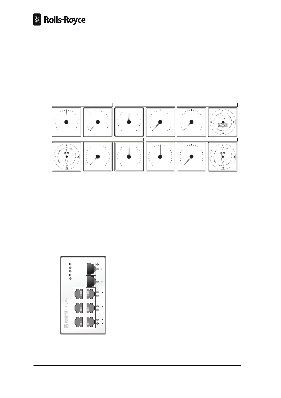
3.4 Indicators
BOW AZIMUTH THRUSTER 1BOW THRUSTER 2
STBD MAIN PROPULSIONPORT MAIN PROPULSION
MIN MAX
RPM
MIN MAX
RPM
ASTERN AHEAD
PITCH
ASTERN AHEAD
PITCH
PORT STBD
PITCH
MIN MAX
RPM
BOW THRUSTER 1
PORT STBD
PITCH
MIN MAX
RPM
MIN MAX
RPM
DC 1
DC 2
FRNT
ST 1
ST 2
1
2
3
4
5
6
7
8
ON
The indicators give feedback on various data and can be found on the bridge and in the
engine control room.
There are three main types of indicators:
• Azimuth indicator
• RPM indicator
• Pitch indicator
In addition a bridge order indicator may be delivered on some vessels.
System Description
3.5 Viewcon
Network cabinet
The network cabinet(s) contains several switches. The network cabinet(s) connects the
panel PCs and the controller cabinets.
Network
Operator stations and electronic units are linked together in an Ethernet network. The
network is single and may contain several separate switches.
(CAN bus is the internal communication between levers, I/O modules and Marine
Controller.)
Page 8 of 16 Doc. No.: 13S000411
Copyright © 2010 Rolls-Royce plc
Revision: A
Page 23

System Description
3
3.6 Controller cabinet
Usually located on bridge or in instrument room. This cabinet distributes signals to and
from the bridge and ECR. It controls all the signals from the Helicon X3 and send them
to the I/O cabinet. There is one controller cabinet per propeller/thruster.
Communicates with the I/O cabinet located in the thruster room.
1 2
Marine Controller Marine Controller
3
7
8
1. Rolls-Royce Marine Controller (Normal)
2. Rolls-Royce Marine Controller (Backup)
3. I/O modules
4. Power distribution
5. Network switches and terminals
6. Signal isolation amplifiers (optional)
7. Power Distribution
8. Main power supply (AC) / fuses
9. Backup power supply (DC) / fuses
4
5
6
9
3.7 I/O Cabinet
The I/O cabinet is often located in the thruster room near sensors and actuators. This
cabinet distributes signals to the different propulsion/thruster units. There is one I/O unit
per propeller/thruster.
The I/O cabinet sends signals to the actuators on the propellers/thrusters and receives
signals from the sensors. There is CAN bus communication between each I/O and
controller cabinet.
Revision: A
Copyright © 2010 Rolls-Royce plc
Page 9 of 16Doc. No.: 13S000411
Page 24

System Description
6
1
7
2
3
4
5
1. I/O modules
2. Capacitors (optional)
3. Power distribution
4. Power distribution
5. Power / network / CANBus terminals
6. Local panel connection
7. Actuator interface card(s) (optional)
8. Relays (optional)
9. Signal isolation amplifiers (optional)
10. I/O terminals
8
9
10
4Functions
Tunnel Thruster Control Functions
The control functions included in the Tunnel Thruster Control system:
• Pitch control
• Command transfer
Main Propulsion Azimuth Control Functions
The control functions included in the Main Propulsion Azimuth Control system:
• RPM control
• Azimuth control
• Command transfer
4.1 Pitch Control
The function of the pitch controller is to move the propeller blades in accordance to the
control lever order. The actuator unit represents the interface between the remote control
and the main servo system, which performs the actual positioning of the blades.
Page 10 of 16 Doc. No.: 13S000411
Copyright © 2010 Rolls-Royce plc
Revision: A
Page 25

System Description
3
4.1.1 Normal Control
The output from the pitch controller is computed on the basis of the input signals from
pitch lever and the actuator position feedback.
Lever and feedback signals are scaled and checked against adjustable limits, with
corresponding alarm for exceeding the normal range. The levers have one set of
adjustments (minimum, zero and maximum) for each manoeuvre station. Multiple sets
of feedback adjustments (minimum, zero and maximum) are available for various
engine power take-outs.
In combined mode the lever signal is modified in a Combinator program, see chapter
Pitch and RPM Combinatory (combined Control).
4.1.2 Backup Control
The Backup Control system consists of closed loop control identical to the Normal
Control system. The Backup Control is a separate system, and is independent of the
Normal Control system. A system failure in the Normal Control system will
automatically switch to and engage the Backup Control.
Lever order signals and feedback are monitored and verified against adjustable alarm
limits. If the signals exceed the limits this will release an alarm to the alarm plant and
both visual and audible system failure alarm will be actuated at the manoeuvre stations.
4.1.3 Backup Control Operation
If a failure occurs on important parts of the Normal Control for the Pitch, Azimuth or
RPM Control function, the control will automatically be switched over to the Backup
Control system. A system failure audible and visible alarm will be activated on each of
the control panels.
The thruster control will continue to follow the lever in command and transfer is done
by using the common in command buttons. The command can be transferred between
all bridge position and the bridge control levers will continue to work as in normal
control.
A failure that occurs on important parts of the Backup Control for the Pitch, Azimuth or
RPM Control function will not affect the Normal Control system. If a system failure
occurs on the Backup Control an audible and visible alarm will be activated on each of
the control panels.
4.1.4 Backup Control Limitations
The Backup Control system has only interface to the control levers. The Backup Control
system does not have interface to External Control systems like Dynamic positioning
systems, Joysticks or Autopilots.
Note: No pitch reduction or load function are included in the Backup system.
When operating using the backup system, the operator must be careful not to overload
the engine or the propeller system.
4.1.5 Local Control
If both the Remote Control system and the Backup Control should fail it is possible to
Revision: A
Copyright © 2010 Rolls-Royce plc
Page 11 of 16Doc. No.: 13S000411
Page 26

operate the propeller pitch locally from the pitch control valve.
4.1.6 Pitch Indication
The Pitch Indication system is independent of the Normal Pitch Control system by
means of separate transmitters and electronic circuits. The pitch indicators are connected
in series and are driven from the Backup Control system.
4.1.7 Pitch Order Scaling
The system may need to reduce the pitch order for different reasons. The pitch reduction
can either be activated from a digital or anlogue input signal.
To reserve engine power to heavy consumers as alternators, fire pumps, etc., it may be
necessary to reduce the available propeller output power. This is normally done by
means of a fixed propeller pitch reduction.
If the drive motor is a diesel engine the system is prepared to handle a fuel limiter
contact, from the RPM governor (i.e. high scavange air pressure). If the contact is closed
the pitch order will stop increasing to a higher value, only decrease of pitch order against
zero is possible.
For azimuth thrusters, a pitch reduction will be activated if the azimuth order is changed
faster then the thruster azimuth servo can follow.
System Description
4.2 Thruster Azimuth Control
The azimuth control function is to obtain the correct thruster azimuth position in
accordance to the control lever order. Valve controlled hydraulic motors or frequency
controlled electro motors perform the positioning of the thruster azimuth.
Detailed information regarding the hydraulic system or motor data is available in the
Thruster Instruction manual.
Note: Test point angle signals are ranged +/- 100%, representing +/- 180 degrees.
Some test points are named with degrees, displaying the angle in degrees
(+/- 180 degrees).
4.2.1 Normal Control
The azimuth controller computes the thruster position and order on the basis of signals
from the thruster feedback and control levers. A two-wiper linear potentiometer
provides two outputs with 90 degrees of phase shift named cosine and sine phase
respectively.
The lever order signals and feedback signals are monitored and verified against alarm
limits. If the signals exceed the limits this will release an alarm to the alarm plant with
a visual and audible system failure alarm on the manoeuvre stations.
4.2.2 Backup Control
The Backup Control system consists of closed loop control identical to the normal
control system. The Backup Control is a separate system, and is independent of the
Normal Control system. A system failure in the Normal Control system will
Page 12 of 16 Doc. No.: 13S000411
Copyright © 2010 Rolls-Royce plc
Revision: A
Page 27

System Description
3
automatically switch to and engage the Backup Control.
Lever order signals and feedback are monitored and verified against adjustable alarm
limits. If the signals exceed the limits this will release an alarm to the alarm plant with
a visual and audible system failure alarm on the manoeuvre stations.
4.2.3 Backup Control Operation
If a failure occurs on important parts of the Normal control for the Pitch/Azimuth/RPM
control function, the control will automatically be switched over to the backup control
system. A system failure audible and visible alarm will be activated on each of the
control panels.
The thruster control will continue to follow the lever in command, and command
transfer is done by using the common in command buttons. The command can be
transferred between all bridge position and the bridge control levers will continue to
work as in Normal Control.
A failure that occurs on important parts of the Backup control for the Pitch/Azimuth/
RPM control function, will not affect the Normal control system. If a system failure
occurs on the Backup Control an audible and visible alarm will be activated on each of
the control panels.
4.2.4 Backup Control Limitations
The backup control system has only interface to the control levers. The backup control
system does not have interface to external control systems like Dynpos, Joystick or
Autopilot.
Note: No azimuth restrictions or load control functions are included in the
backup system.
When operating using the backup system, the operator must be careful not to overload
the engine or the propeller system.
4.2.5 Local Control
Local control is used if both the normal control and the backup control fail to operate the
thruster azimuth. The thruster azimuth can be operated locally on the actuator unit. The
Control System must first be disconnected from the actuator unit. This can be done by
means of the Local Control switch mounted in front of the Actuator Interface Unit, or
by disconnecting the plug from the actuator unit. If frequency converter used, operate
service switch inside converter cabinet.
The Thruster Instruction Manual will give more details for Local Control operation.
4.2.6 Azimuth Indication
The azimuth indication system independent of the normal control system by means of
separate transmitters and electronic circuits. The Azimuth indicators are connected in
series, and are driven from the Backup Control system.
Copyright © 2010 Rolls-Royce plc
Revision: A
Page 13 of 16Doc. No.: 13S000411
Page 28

4.3 RPM Control
The RPM Control function system controls the speed signal to the frequency converter
for electrical drives or the engine governor for diesel or gas engines.
4.3.1 RPM Control Electric Drive Motor
The RPM Control system includes selection of different operational modes:
• Separate Mode
• Combined Mode
Selection between modes is possible by means of push buttons. RPM Control can be
managed from engine control room only or from additional control panels.
4.3.2 External RPM Control
External RPM order signals from system as DP/Joystick/Auxiliary systems can be
connected to the rpm controller.
The external rpm signal are checked against adjustable preset limits. Any error
conditions on the rpm input signal will initiate a warning to the alarm plant and an error
message will be displayed on the control panel.
System Description
4.3.3 RPM Order Output
The output signal from the controller is scaled to meet the actuator signal range from idle
to full rpm, and then fed to external governor, IP converter or frequency converter. The
output will follow a linear curve between idle and full rpm order.
The RPM output rate of change is adjustable and can be adapted to the engine/frequency
converter reversing speed from idle to full rpm (increasing order) and vice versa
(decreasing order).
4.3.4 Propeller/Shaft RPM Indication
The propeller/shaft RPM indicators are connected in series and are driven from the
Backup Control system.
4.4 Command Transfer
The term Command transfer is used to describe the procedure performed when the
control is transferred between manoeuvre stations without acceptance on either of the
stations. This is normally the procedure between wheelhouse (bridge) stations.
5 Location of Manufacturing Number
5.1 Marking Locations
Electrical cabinets and junction boxes are physically marked with a unique tag, and also
on all applicable drawings. The I/O cabinets are marked with the Rolls-Royce logotype
in the upper left corner.
Page 14 of 16 Doc. No.: 13S000411
Copyright © 2010 Rolls-Royce plc
Revision: A
Page 29
System Description
3
The Rolls-Royce logotype is imprinted in remote control panels, alarm panels and cabin
panels.
Cables are marked with a cable tag at both ends.
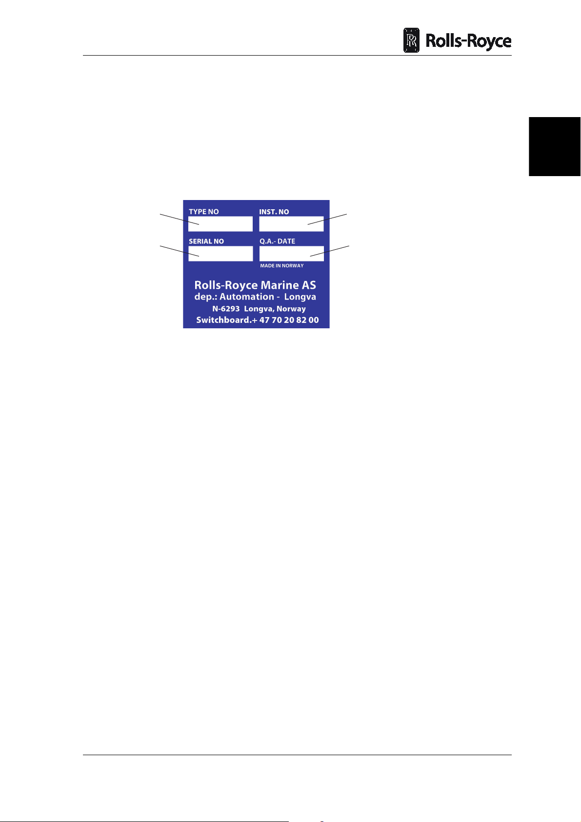
5.1.1 Company Identification
The Rolls-Royce Company Identification sticker shows where the product has been
produced and is found on discrete places on all delivered items, e.g. on the inside of the
cabinet doors.
1
2
Figure 4 Company Identification Sticker
Pos Denomination Meaning
1 TYPE NO Corresponding drawing number with the revision letter in
closed brackets
2 SERIAL NO Production order number
3 INST. NO Installation number
4 Q.A. DATE Date and signature by test responsible
3
4
Revision: A
Copyright © 2010 Rolls-Royce plc
Page 15 of 16Doc. No.: 13S000411
Page 30

System Description
Page 16 of 16 Doc. No.: 13S000411
Copyright © 2010 Rolls-Royce plc
Revision: A
Page 31

4
Delivery Specification
1 General .........................................................................................................3
Copyright © 2010 Rolls-Royce plc
The content of this document is the property of Ro lls-Royce plc and may not be redistributed in whole or in part thereof without
express written consent of Rolls-Royce plc.
Doc. No.: 13S000411
Revision: A
Page 32

Doc. No.: 13S000411
Revision: A
Copyright © 2010 Rolls-Royce plc
Page 33

Delivery Specification
4
1 General
For Delivery specification see the Technical specification.
Note: Upon reception of the Rolls-Royce equipment, the receiver must compare
the shipping documents with the physical items received. If any
discrepancy is found, Rolls-Royce must be informed immediately.
Revision: A
Copyright © 2010 Rolls-Royce plc
Page 3 of 4Doc. No.: 13S000411
Page 34

Delivery Specification
Page 4 of 4 Doc. No.: 13S000411
Copyright © 2010 Rolls-Royce plc
Revision: A
Page 35

Rev.
Date:
Sign.
Changed
pages:
Description:
-
17.01.2012
TR
-
New specification
15.01.2013
OHV
New project number
Technical Specification
Propulsion & Thruster Control System
Project no. : 20-12-00136
Version : Vessel type (design) : UT535E
Customer Project no. : RRM STO – P12/7210
Shipowner :
Shipyard :
Yard no. :
Rolls-Royce Marine
Propulsion Ulstein Unit nos : 2xTT CP (bow), 2xUS FP (main)
Author(s): Trude Rånes
This document is the property of Rolls-Royce and may not be redistributed or reproduced in any way, without the written permission of Rolls-Royce.
Failure to do so is a violation of copyright laws.
P&T Control_20-12-00136_UT535E_Brasil _V2
Page 1 of 14
Page 36

Table of contents
00.01 GENERAL .................................................................................................................... 3
01.00 SCOPE OF SUPPLY/ TECHNICAL DESC RIP TI ON .................................................... 5
01.01 System Ove r vie w ......................................................................................................... 5
01.02 Description of equipment common for all propulsion units ........................................... 6
Control Stations .......................................................................................................................... 6
Control panel functions ............................................................................................................... 7
Control lever functions ................................................................................................................ 8
01.03 Description of equipment for main thruster units (diesel-electric systems). ................. 9
Cabinets ..................................................................................................................................... 9
Interface to external systems ..................................................................................................... 10
01.04 Description of equipment for bow tunnel thrusters ....................................................... 12
Cabinets ..................................................................................................................................... 12
Interface to external systems ..................................................................................................... 13
01.05 Spare Parts and Tools .................................................................................................. 14
This document is the property of Rolls-Royce and may not be redistributed or reproduced in any way, without the written permission of Rolls-Royce.
Failure to do so is a violation of copyright laws.
P&T Control_20-12-00136_UT535E_Brasil _V2
Page 2 of 14
Page 37

00.01 General
Remote control
Type of remote control : Propulsion and Thruster
Power supply to remote control (main supply) : 230V AC 50/60 Hz
Power supply to remote control (backup supply) : 24V DC from ships battery
Classification requirements
Survey : DNV +1A1, SF, E0, OILREC, Fire
Fighter 1, DYNPOS AUT (DP1),
CLEAN
The equipment is dimensioned in accordance with the above classification society rules valid on
the date of this specification.
Equipment not supplied
Scope of supply is defined in the technical specification.
Not included in scope of supply are:
- External cabling
- Cable glands.
- 24 V DC power supply
Technical information - Drawings
Dimension drawings, wiring diagrams, technical data and installation instruction for the propulsion
remote control system will be delivered. All accordi ng to documentation list issued for each order.
Workshop testing
The propulsion remote control system is workshop tested according to the class requirement and
RRM standard.
Shipment
Depending on transport methods and delivery time’s components may be shipped separately.
Installation into the ship and mounting of components are client's responsibility if not otherwise is
stated.
Safe storage
All equipment is prepared for storage in dry and dust free environments up to 6 months from
delivery.
This document is the property of Rolls-Royce and may not be redistributed or reproduced in any way, without the written permission of Rolls-Royce.
Failure to do so is a violation of copyright laws.
P&T Control_20-12-00136_UT535E_Brasil _V2
Page 3 of 14
Page 38

Cabling
Connections between components supplied by RRM are the client's responsibility. However, cable
type recommendations are given in the diagrams and mounting instructions.
Installation, inspection, starting up and seatrial
Installation of the propulsion remote control system in the ship and mounting of components are
the client's responsibility if not otherwise stated.
Instruction manuals - Language
Users Manuals and Installation Manuals in English language containing all technical data, are
included.
All drawings, documents and sign plates on the equipment will also be delivered in English
language.
This document is the property of Rolls-Royce and may not be redistributed or reproduced in any way, without the written permission of Rolls-Royce.
Failure to do so is a violation of copyright laws.
P&T Control_20-12-00136_UT535E_Brasil _V2
Page 4 of 14
Page 39

Example only, project dependent
01.00 Scope of supply/ technical description
01.01 System Overview
The Propulsion & Thruster control system is a mic roprocessor based system. Following main functions
are included:
- Speed control, allowing accurate and reliable cont rol of the motor speed (RPM).
- Pitch control, allowing accurate and reliable control of the t hruster pitch.
- Direction control, allowing accurate and reliable contr ol of the thrust direction.
- Follow-up backup control from control lever.
This document is the property of Rolls-Royce and may not be redistributed or reproduced in any way, without the written permission of Rolls-Royce.
Failure to do so is a violation of copyright laws.
P&T Control_20-12-00136_UT535E_Brasil _V2
Page 5 of 14
Page 40

01.02 Description of equipment common for all propulsion units
Control Stations
The purpose of the control stations is:
- Selection and indication of panel In Command
- Selection and indication of operational modes, settings and functions
- Selection and indication of thruster status and thruster settings.
- System and operational alarm indication
- Monitoring of signals
Main Bridge control station (Aft)
2 pc. Main propulsion (azimuth ) - Combined Speed and Steering control lever
1 pc. Bow 1/ 2 Tunnel thrusters - Pitch control lever (double)
1 pc. 10.4” LCD - high-resolution colour dis pl ay with touch-screen interface and built-in display
computer.
Indicator panel in overhead console:
2 pcs. Pitch indicator.
2 pcs. Propeller RP M i ndi cat or.
2 pcs. Steering indicator.
Emergency stop panel for thrusters:
4 pcs. Emergency Stop push buttons, hardwired to the variable speed drive (alternati vely to the main
switchboard).
Slave Bridge control station (Fore)
2 pc. Main propulsion (azimuth ) - Combined Speed and Steering control lever
1 pc. Bow 1/ 2 Tunnel thrusters - Pitch contr ol l ever (double)
1 pc. 10.4” LCD - high-resolution colour displa y with touch-screen interface and built-in display
computer.
Indicator panel in overhead console:
2 pcs. Pitch indicator.
2 pcs. Propeller RP M i ndi cat or.
2 pcs. Steering indicator.
Emergency stop panel for thrusters:
4 pcs. Emergency Stop push buttons, hardwired to the variable speed drive (alternatively to the main
switchboard).
ECR station
1 pc. 10.4” LCD - high-resolution colour displa y with touch-screen interface and built-in display
computer.
This document is the property of Rolls-Royce and may not be redistributed or reproduced in any way, without the written permission of Rolls-Royce.
Failure to do so is a violation of copyright laws.
P&T Control_20-12-00136_UT535E_Brasil _V2
Page 6 of 14
Page 41

Control panel functions
Any operation of the system can be performed through the graphical interface. The most vital operations
can in addition be performed by using dedicat ed pushbuttons in the control lever base (see next section).
Summary of features on the screen:
- LAN contact
- Dimmer
- Speaker (not used)
- 24V power input
Display pages
The Main View Page includes the following:
- A shortcut area where the detail-level pages can be r eached.
- An area for COMMON IN COMMAND for all the thrusters.
- A vessel overview area with graphical and numeric information of all thrusters:
- Indication thruster pitch command and actual pitc h feedback
- Indication thruster steering command and actual steering feedback.
- Indication thruster speed command and actual propeller speed.
When selecting one of the detail pages these will replace the overview area. The short-cut area will
remain available from all pages.
Thruster page information is project depende nt. Below are typical examples of each propeller/ thruster
type:
Main Thruster (diesel-electric system) p ages includes the following functions:
- Indication thruster steering command and act ual steering feedback.
- Indication thruster speed command and actual propeller speed.
- Selection and indication of IN COMMAND.
- Indication of STEERING LOCAL CONTROL.
- Indication of SPEED LOCAL CONTROL.
- Indication of ZERO LEVER.
- Selection and indication of START/ STOP OF SYSTEM.
- Selection and indication of START/ STOP O F THRUSTER.
- Selection and indication of COMMON PORT CO NTRO L.
(Common control of both thrusters from port lever).
- Selection and indication of AUTOPILOT ON/OFF .
- Indication of DP/JOYSTICK CONTROL.
- Indication of POWER REDUCED.
- Dimming of lever.
Tunnel Thruster page includes the following funct i ons:
- Indication thruster pitch command and actual pi tch feedback.
- Selection and indication of IN COMMAND.
- Indication of SPEED LOCAL CONTROL.
- Selection and indication of START/ STOP OF SYSTEM.
- Selection and indication of START/ STOP O F THRUSTER.
- Indication of DP/JOYSTICK CONTROL.
- Indication of POWER REDUCED.
- Dimming of lever.
This document is the property of Rolls-Royce and may not be redistributed or reproduced in any way, without the written permission of Rolls-Royce.
Failure to do so is a violation of copyright laws.
P&T Control_20-12-00136_UT535E_Brasil _V2
Page 7 of 14
Page 42

The Alarm Page is common for all thrusters and includes the following:
- Listing of all alarms relevant for the contr ol sy st em (alarm buzzer in control lever base)
- Acknowledge of all alarms (alarm buzzer may also be silenced from button in control lever base)
- Acknowledged alarms remains until error condition disappears.
Viewcon (1 pc.)
The unit is designed for bulkhead mounting and should be located on the bridge. Cable access is through
a cover plate that can be removed for fitting of cable glands. Location of the unit should be selected with
due to emphasis on service access.
The Viewcon cabinet includes a switch for routin g of Ethernet signals to the bridge control panels.
Control lever functions
Potentiometers and electronics for I/Os and control, both for normal and backup system, are included
inside the lever. The display in the base shows set c ommand (pitch and direction) from the lever.
Symbol Command Description
In operation/running Thruster is started and rea dy to use.
Control transfer
Command transfer
Backup control
Alarm
Transfer command between bridge and
ECR
Take command. If light is lit, the lever is
in command
Independent controller that takes over if
the main controller stops. Redundant
system.
Alarm indicator, see alarm screen for
details.
This document is the property of Rolls-Royce and may not be redistributed or reproduced in any way, without the written permission of Rolls-Royce.
Failure to do so is a violation of copyright laws.
P&T Control_20-12-00136_UT535E_Brasil _V2
Page 8 of 14
Page 43

01.03 Description of equipment for main thruster units (diesel-electric
systems).
Cabinets
Electronic unit (one per unit)
The electronic unit is designed for bulkhead mou nting and should be mounted in the instrument room or
nearby the bridge. (Note! Electronic unit must not under any ci rcumstance s be rem oved from the
electronic cabinet and mounted into any console separately). Cable access i s t hrough a coverplate
that can be removed for fitting of cable gl ands. Location of the unit should be selected due emphasis on
service access.
The electronic unit contains the following:
- Power supply
- Application CPUs (Main and backup) including flash memory
- CAN fieldbus
- Ethernet communication with control panels
- I/O cards (DI, DO, AI, AO, serial line interfaces)
- Circuitry monitoring w/alarm output
- Indication circuitry
- Cable termination
Power Supply requirement:
Main supply : 230 VAC (+/- 15%) 50/60 Hz
Back-up supply : 24 VDC (+20% - 17%) (Battery back-up)
Power consumption: : Typical 100 - 200 watt
The Remote Control System is designed to acc om plish prevailing rules of DNV, ABS, LRS, BV, GL and
RINA.
Distributed IO cabinet (one per unit)
The unit is designed for bulkhead mounting and should be located in the thruster room. Cable access is
through a cover plate that can be removed for f itting of cable glands. Location of the unit should be
selected with due to emphasis on service access.
The IO cabinet contains the following:
- I/O to/from external connections.
- Power supply
- CAN field bus
- Cable termination
- Local indicator/Control panel
Lub pump control unit (one per main thruster)
The unit selects duty and stand-by pump and is desi gned for bulkhead mounting and should be located
close to the lub. pumps. Cable access is through cable glands. Location of the unit should be selected
with due to emphasis on service access.
This document is the property of Rolls-Royce and may not be redistributed or reproduced in any way, without the written permission of Rolls-Royce.
Failure to do so is a violation of copyright laws.
P&T Control_20-12-00136_UT535E_Brasil _V2
Page 9 of 14
Page 44

Interface to external systems
Interface to drive motor starter. (Project dependent. To be settled at interface meeting)
- Drive motor RPM order signal, 4 - 20 mA.
The signal has to be galvanic isolated at the governor side.
- RPM feedback signal
4-20mA signal from the frequency converter. Closed when frequency converter fault.
- Common Alarm Drive RPM (Reduce load)
Potential free contact from the frequency converter. Closed = frequency converter alarm
- Frequency Converter fault/ trip (autostop).
Potential free contact from the frequency conv ert er. Closed = frequency converter fault.
- Frequency Converter reset.
Potential free contact to the frequency conv ert er. Closed = reset (pulse)
- Start Frequency Converter
Potential free contact to the frequency converter. Closed = start (pulse)
- Stop/ Autostop Frequency Converter
Potential free contact to the frequency converter. Closed = stop (pulse)
- Emergency Stop Frequency Converter
Potential free contact to the frequency converter. Closed = stop (pulse)
Loop monitored in Frequency Converter (resist ors in each control panel)
- Interlock start/Auto stop Motor
In case of too low gear lub. oil pressure, a potent i al free relay contact is given to the engine control
system for immediately stop of the engine.
Open = stop.
- Frequency Converter ready to run if handle out of zero.
Potential free contact from the frequency conv ert er.
Closed = frequency converter started.
- Power limitation.
Potential free contact from the frequency conv ert er. Closed = power limited in drive.
- Local/ emerg. control
Potential free contact from the frequency conv ert er. Closed = local
DP Interface
The remote control is provided with interface for an ICON DP system.
Communication is via Ethernet.
(Other DP system will be interfaced through hardwired signals)
Signals required from the DP system:
- Closing contact (potential free) to engage the DP m ode. (From selector switch).
- Request for control.
- Speed control signal
- Steering control signal
Signals available to the DP system:
- Remote control is ready for DP
- Remote control acknowledge of DP mode.
- Propeller RPM feedback signal
- Steering feedback signal
- Power reduced signal
This document is the property of Rolls-Royce and may not be redistributed or reproduced in any way, without the written permission of Rolls-Royce.
Failure to do so is a violation of copyright laws.
P&T Control_20-12-00136_UT535E_Brasil _V2
Page 10 of 14
Page 45

Joystick Interface
The remote control is provided with interf ace f or a P OSCON Joystick system.
Communication is via Ethernet.
(Other joystick system will be interfaced through hardwired signals)
Signals required from the JOYSTICK system:
- Closing contact (potential free) to engage the JOYSTICK mode. (From selector switch).
- Request for control.
- Speed control signal
- Steering control signal
Signals available to the JOYSTICK system:
- Remote control is ready for JOYSTICK
- Remote control acknowledge of JOYSTICK mode.
- Propeller RPM feedback signal
- Steering feedback signal
- Power reduced signal
Autopilot interface
The remote control is provided with interface for an Autopilot system.
Signal required from the Autopilot:
- Steering control signal
-10VDC for 30 degrees, turning clock wi se
0VDC for straight ahead 0 degrees.
+10VDC for 30 degrees, turning counter clo ck wise
The signal to be galvanic isolated at the AP system
Signal available to the AP system:
- Closing contact (potential free) when the remote control is ready for AP.
ACON Interface
The remote control is provided with interf ace f or an ACON Automation system.
Communication is via Ethernet.
(Other automation system will be interfaced through serial line or hardwired signals)
Signal available to the ACON system:
- Thruster alarms.
- Thruster running.
- Steering feedback signal
- Propeller RPM feedback signal
This document is the property of Rolls-Royce and may not be redistributed or reproduced in any way, without the written permission of Rolls-Royce.
Failure to do so is a violation of copyright laws.
P&T Control_20-12-00136_UT535E_Brasil _V2
Page 11 of 14
Page 46

01.04 Description of equipment for bow tunnel thrusters
Cabinets
Electronic unit (one per unit)
The electronic unit is designed for bulkhead mount i ng and should be mounted in the instrument room or
nearby the bridge. (Note! Electronic unit must not under any ci rcumstance s be rem oved from the
electronic cabinet and mounted into any console separately). Cable access i s t hrough a coverplate
that can be removed for fitting of cable glands. Location of the unit should be selected due emphasis on
service access.
The electronic unit contains the following:
- Power supply
- Application CPUs (Main and backup) including flash memory
- CAN fieldbus
- Ethernet communication with control panels
- I/O cards (DI, DO, AI, AO, serial line interfaces)
- Circuitry monitoring w/alarm output
- Indication circuitry
- Cable termination
Power Supply requirement:
Main supply : 230 VAC (+/- 15%) 50/60 Hz
Back-up supply : 24 VDC (+20% - 17% ) (Battery back-up)
Power consumption: : Typical 100 - 200 watt
The Remote Control System is designed to acc om plish prevailing rules of DNV, ABS, LRS, BV, GL and
RINA.
Distributed IO cabinet (one per unit)
The unit is designed for bulkhead mounting and should be located in the thruster room. Cable access is
through a cover plate that can be removed for f itting of cable glands. Location of the unit should be
selected with due to emphasis on service access.
The IO cabinet contains the following:
- I/O to/from external connections.
- Power supply
- CAN field bus
- Cable termination
- Actuator interface Pitch
This document is the property of Rolls-Royce and may not be redistributed or reproduced in any way, without the written permission of Rolls-Royce.
Failure to do so is a violation of copyright laws.
P&T Control_20-12-00136_UT535E_Brasil _V2
Page 12 of 14
Page 47

Interface to external systems
Interface to drive motor starter
The following signals are given to the drive motor starter:
- Zero Pitch Signal.
A potential free relay contact for interlock st art of thruster motor.
The contact is closed at zero pitch position.
- Start motor.
Impulse push button for start of motor (normal ly open - closes for start)
- Stop motor.
Impulse push button for stop of motor (normally closed - opens for stop)
- Emergency stop motor.
Impulse push button for emergency stop of motor.( normally closed – opens for stop)
- Servo pump running.
Potential free relay contact from servo p um p st arter, opens when servo pump stops.
The following signals are required from the driv e m otor starter to the control system:
- Running signal
A potential free relay closing contact when the motor is running and ready for thruster operation.
Indication light on the START push button on Mai n Bridge Panel.
- Overload signal (high temp. in windings). A potential free relay contact from the thermal relay for
overload indication in control panels.
- Drive motor current signal.
4-20mA signal from the drive motor starter.
The load control continuously monitors the power output from the drive motor and the propeller pitch
is automatically adjusted in response to the load changes detected.
DP Interface
The remote control is provided with interf ace f or an ICON DP system.
Communication is via Ethernet.
(Other DP system will be interfaced through hardwired signals)
Signals required from the DP system:
- Closing contact (potential free) to engage the DP m ode. (From selector switch).
- Request for control.
- Pitch control signal
Signals available to the DP system:
- Remote control is ready for DP
- Remote control acknowledge of DP mode.
- Pitch feedback signal
- Power reduced signal
This document is the property of Rolls-Royce and may not be redistributed or reproduced in any way, without the written permission of Rolls-Royce.
Failure to do so is a violation of copyright laws.
P&T Control_20-12-00136_UT535E_Brasil _V2
Page 13 of 14
Page 48

Joystick Interface
The remote control is provided with interf ace f or a P OSCON Joystick system.
Communication is via Ethernet.
(Other joystick system will be interfaced through hardwired signals)
Signals required from the JOYSTICK system:
- Closing contact (potential free) to engage the JOY S T ICK mode. (From selector switch).
- Request for control.
- Pitch control signal
-
Signals available to the JOYSTICK system:
- Remote control is ready for JOYSTICK
- Remote control acknowledge of JOYSTICK mode.
- Pitch feedback signal
- Power reduced signal
ACON Interface
The remote control is provided with interf ace for an ACON Automation system.
Communication is via Ethernet.
(Other automation system will be interfaced thr ough serial line or hardwired signals)
Signal available to the ACON system:
- Thruster alarms
- Pitch feedback signal
01.05 Spare Parts and Tools
One set RRM standard spare parts for two years operation, consisting of:
- Fuses for remote control.
- Bulbs for remote control.
This document is the property of Rolls-Royce and may not be redistributed or reproduced in any way, without the written permission of Rolls-Royce.
Failure to do so is a violation of copyright laws.
P&T Control_20-12-00136_UT535E_Brasil _V2
Page 14 of 14
Page 49

5
Technical Data
1 General .........................................................................................................3
2 Environmental Data ..................................................................................... 4
3 Electrical Data .............................................................................................. 4
3.1 Power Supply ................................................................................................4
3.2 I/O Modules ...................................................................................................4
3.3 Levers ............................................................................................................ 4
3.4 10.4 inches LCD ............................................................................................4
Copyright © 2010 Rolls-Royce plc
The content of this document is the property of Ro lls-Royce plc and may not be redistributed in whole or in part thereof without
express written consent of Rolls-Royce plc.
Doc. No.: 13S000411
Revision: A
Page 50

Doc. No.: 13S000411
Revision: A
Copyright © 2010 Rolls-Royce plc
Page 51

Technical Data
5
1 General
This section provides the technical data of the Helicon X3 system, with focus on the
main hardware components. Detailed drawings and interface descriptions are found in
the delivery specific drawings, see chapter 12 Design Drawings.
The Helicon X3 system is designed to meet the type approval requirements stated by EU
standards and the following classification societies:
• American Bureau of Shipping (ABS)
• Bureau Veritas (BV)
• China Classification Society (CCS)
• Det Norske Veritas (DNV)
• Germanischer Lloyds (GL)
• Korean Register of Shipping (KR)
• Lloyd’s Register (LR)
• Nippon Kaiji Kyokai (NK)
• Registro Italiano Navale (RINA)
• Russian Maritime Register of Shipping (RS)
• Croatian Register of Shipping (Hrvatski Register Brodova) (CRS)
• Indian Register of Shipping (IRS).
Revision: A
Copyright © 2010 Rolls-Royce plc
Page 3 of 4Doc. No.: 13S000411
Page 52

2 Environmental Data
Temperature: 0–70 °C ambient
Humidity: 97 %
Vibration: 3–100 Hz, frequency ranges
3-13.2 Hz, displacement limited to 1 +/- 1.0 mm
13.2-100 Hz, acceleration limited to 0.7G
EMC: According to the rules of the Classification Societies, and the
IEC945 standard for Electromagnetic Compatibility
Enclosure: IP22 (Control room, Accommodation and Bridge)
IP44 (Engine room)
3 Electrical Data
3.1 Power Supply
Technical Data
Main supply 230 VAC (85-264VAC) 50/60 Hz
Backup supply 24 VDC (18-32 VDC) (Battery backup)
Power consumption Typical 100-200 Watt
3.2 I/O Modules
Analogue inputs 12 bit +/-0.5% absolute accuracy
Analogue outputs 12 bit +/-0.5% absolute accuracy
3.3 Levers
Analogue inputs 10 bit +/- 0.4% linear error, and +/- 1% absolute accuracy
3.4 10.4 inches LCD
Power supply 24VDC +20%, -17%
Power consumption 50 Watt max
Page 4 of 4 Doc. No.: 13S000411
Copyright © 2010 Rolls-Royce plc
Revision: A
Page 53

6
Operating Instructions
1 General .........................................................................................................3
2 Controlling the thrusters ............................................................................3
2.1 System Overview ...........................................................................................3
3 Standard Operations ...................................................................................8
3.1 Port/Stbd Main Propulsion .............................................................................8
3.2 Bow/Stern Tunnel Thruster ............................................................................8
3.3 In Command ..................................................................................................8
3.4 RPM / Power Mode .......................................................................................9
3.5 Start/Stop pump ............................................................................................9
3.6 Start/Stop thruster .......................................................................................10
3.6.1 Start Thruster ...................................................................................10
3.6.2 Stop Thruster ....................................................................................11
3.7 Reset Drive ..................................................................................................11
3.8 Separate/Common Lever ............................................................................12
3.9 Autopilot ......................................................................................................12
3.9.1 Enabling / Disabling Autopilot ...........................................................12
3.9.2 Automatic Autopilot Disengage ........................................................13
4 Alarm ..........................................................................................................13
4.1 Silence .........................................................................................................14
4.1.1 Alternative 1 .....................................................................................14
4.1.2 Alternative 2 .....................................................................................14
4.2 Acknowledge All ..........................................................................................15
4.2.1 Alternative 1 .....................................................................................15
4.2.2 Alternative 2 .....................................................................................15
4.3 Wash screen ................................................................................................15
4.4 Lever Light ...................................................................................................15
4.5 Day/Night .....................................................................................................16
5 Steering the Ship with Azimuth Thrusters ..............................................16
5.1 Position Keeping .........................................................................................16
5.2 Ahead ..........................................................................................................17
5.3 Astern ..........................................................................................................18
6 Crash Stop .................................................................................................18
6.1 Crash Stop Procedure .................................................................................18
7 Backup Operation ......................................................................................19
7.1 Steering Backup Control at Bridge or Engine Control Room .......................19
7.2 Steering (direction) Local Control ................................................................20
7.3 Steering (direction) Emergency Operation, Local ........................................20
8 Emergency Operation ...............................................................................20
8.1 Emergency Control/Local Control ................................................................20
8.1.1 From Bridge ......................................................................................21
8.1.2 From Thruster Room ........................................................................21
Copyright © 2010 Rolls-Royce plc
The content of this document is the property of Ro lls-Royce plc and may not be redistributed in whole or in part thereof without
express written consent of Rolls-Royce plc.
Doc. No.: 13S000411
Revision: A
Page 54

Doc. No.: 13S000411
Revision: A
Copyright © 2010 Rolls-Royce plc
Page 55

Operating Instructions
6
1 General
This chapter gives a brief overview on how to operate the Helicon X3 system. For
practical reasons, it is not possible to go into particulars about all available functions.
Instead, the graphical user interface (GUI) is designed to be as self-explanatory as
possible. In the following sections, the most common functions are described in detail.
Caution: Before operating the equipment, please refer to chapter 2, Safety for the
general statement, safety and warnings instructions.
2 Controlling the thrusters
There are three ways of controlling the thrusters with Helicon X3:
• Control lever
• Control panel
• Emergency operation
2.1 System Overview
The system overview page on the control panel gives an overview of the most essential
information for all propulsion units. The system overview page is the normal view if not
activation of functions or alarms require attention to other pages.
The common command change buttons are located on this page. Using these buttons
makes it possible to take command for all thrusters by pressing only one button +
Accept.
Revision: A
Copyright © 2010 Rolls-Royce plc
Page 3 of 22Doc. No.: 13S000411
Page 56

Operating Instructions
1
5
2
6
2
1
3
5
6
3
7
4
7
4
8
8
Figure 1 Example on an Overview of propulsion unit functions
Pos Marking Symbol Thruster (Function)
1 STBD MP Main propulsion (Pitch, RPM, rudder feedback)
2 STERN Tunnel Thruster FP (RPM, power feedback)
3 STERNAZ 1 Azimuth (Pitch, RPM, direction, power feedback)
Page 4 of 22 Doc. No.: 13S000411
Copyright © 2010 Rolls-Royce plc
Revision: A
Page 57

Operating Instructions
6
Pos Marking Symbol Thruster (Function)
4 BOWAZ 1 Azimuth (Pitch, RPM, direction, Power feedback)
5 PORT MP Main propulsion (Pitch, RPM, rudder feedback)
6 STERN 2 Tunnel Thruster FP (RPM, power feedback)
7 BOWAZ 2 Azimuth (Pitch, RPM, direction, power feedback)
8 BOW 1 Tunnel Thruster CP (Pitch, RPM, power feedback)
Revision: A
Copyright © 2010 Rolls-Royce plc
Page 5 of 22Doc. No.: 13S000411
Page 58

Operating Instructions
Figure 2 Screenshot of a typical Azimuth thruster page
Figure 3 Screenshot of a typical Tunnel thruster page
Page 6 of 22 Doc. No.: 13S000411
Copyright © 2010 Rolls-Royce plc
Revision: A
Page 59

Operating Instructions
6
Figure 4 Screenshot of a typical Shaft line as main propulsion page
Revision: A
Figure 5 Screenshot of a typical Azipull as main propulsion page
Copyright © 2010 Rolls-Royce plc
Page 7 of 22Doc. No.: 13S000411
Page 60

Operating Instructions
3 Standard Operations
In this section all available control functions and buttons available in the Helicon X3
user interface is described.
Note: Depending on thruster type and configuration, all functions and buttons
may not be applicable for your installation, or somehow differ from what
is presented here.
3.1 Port/Stbd Main Propulsion
The Port/Stbd Main propulsion page contains all information and functions available for
Main Propulsion systems/thrusters.
3.2 Bow/Stern Tunnel Thruster
The Bow/Stern Tunnel Thruster pages contain all information and functions available
for the tunnel thruster.
3.3 In Command
To operate the lever or activate a function it is necessary to first be In Command.
It is not possible to transfer the control to an unmanned manoeuvre station.
This is how you change responsibility between bridge stations:
1. Set the control levers at the new station in accordance to the position of the levers
at the present station in command.
2. Press the In Command button.
3. To confirm press the Accept button within 10 seconds when it starts to flash.
4. The command is transferred when the In Command button turns blue.
Note: There is normally no command transfer interlock because of discrepancy
between the lever position at the present station in command and the lever
position at the new station to be in command.
Page 8 of 22 Doc. No.: 13S000411
Copyright © 2010 Rolls-Royce plc
Revision: A
Page 61

Operating Instructions
6
3.4 RPM / Power Mode
Rpm Mode
This is the default mode for main propulsion. The drive is set to regard the order as a set
point for a specific rpm, and continuously hold that rpm. There is no limit for conditions
to use this mode.
Power Mode
This is a mode where drive is set to regard the order as a power set point. The drive will
regulate rpm to continuously hold a specific load on the main switchboard. This mode
is mainly meant for transit. This mode will automatically be disabled if DP or Joystick
is enabled. Power mode will also be disabled if the order is less than 20% due to limited
manoeuvrability in low speed.
3.5 Start/Stop pump
Revision: A
Before it is possible to start/stop the pump the manoeuvre station must be In Command.
1. Press the Start or Stop button.
2. To confirm press the Accept button within 10 seconds when it starts to flash.
3. The pump is running when the Start button turns steady green or is stopped when
the Stop button turns steady red.
Copyright © 2010 Rolls-Royce plc
Page 9 of 22Doc. No.: 13S000411
Page 62

3.6 Start/Stop thruster
Operating Instructions
3.6.1 Start Thruster
Before it is possible to start the thruster the following must be fulfilled:
• The manoeuvre station must be In Command.
• The pump must be running.
• The pitch must be below 10%.
1. Press the thruster Start button.
2. To confirm press the Accept button within 10 seconds when it starts to flash.
3. The thruster is running when the Start button turns steady green.
Page 10 of 22 Doc. No.: 13S000411
Copyright © 2010 Rolls-Royce plc
Revision: A
Page 63

Operating Instructions
6
3.6.2 Stop Thruster
Before it is possible to stop the thruster the manoeuvre station must be In Command.
1. Press the thruster Stop button.
2. To confirm press the Accept button within 10 seconds when it starts to flash.
3. The thruster is stopped when the Stop button turns steady red.
3.7 Reset Drive
Reset drive can be performed either form a manoeuvre station In Command or from the
ECR panel-PC.
1. Press the Reset Drive RPM button to reset the drive.
2. To confirm press the Accept button within 10 seconds when it starts to flash.
3. The Reset drive signal is given to the drive. The signal resets the alarm status in
drive.
It is also possible to output Reset signals to the Steering Gear Drives, see the Steering
Gear Manual for details.
Revision: A
Copyright © 2010 Rolls-Royce plc
Page 11 of 22Doc. No.: 13S000411
Page 64

3.8 Separate/Common Lever
It is possible to use Port or Stbd azimuth lever as common lever for the both main
propulsion thrusters, before this can be done the manoeuvre station must be In
Command.
1. Press the Common Stbd button.
2. To confirm press the Accept button within 10 seconds when it starts to flash.
3. Pitch/RPM and azimuth order for Port thruster will now be taken from the Stbd
Lever.
To go back to separate mode the manoeuvre station must be In Command.
1. Press the Separate Lever button.
2. To confirm press the Accept button within 10 seconds when it starts to flash.
3. The main propulsion thrusters will now have separate levers.
Operating Instructions
3.9 Autopilot
3.9.1 Enabling / Disabling Autopilot
It is possible to enable signal from an external Autopilot but the fore bridge must be In
Command before this can be done.
1. Press the Autopilot button.
2. To confirm press the Accept button within 10 seconds when it starts to flash.
3. Azimuth order from the external Autopilot will now control the thrusters.
To enable the lever mode again:
1. Press the Autopilot button.
2. To confirm press the Accept button within 10 seconds when it starts to flash.
3. Lever mode is enabled.
Page 12 of 22 Doc. No.: 13S000411
Copyright © 2010 Rolls-Royce plc
Revision: A
Page 65

Operating Instructions
6
3.9.2 Automatic Autopilot Disengage
The function for automatic disengage of autopilot are trigged by manually operating the
lever while the autopilot mode is selected.
Exceeding an angle of +\- 20 degrees from lever zero position will cause automatic
disengage from the autopilot mode and the system will return to manual mode. This
value is not adjustable. Re-engage of autopilot mode must be manually selected from
operator.
4Alarm
The alarm page contains a list of any active alarms in the control system. Alarms for all
the thrusters connected to the system are presented in this list. The most recent alarm
will be on top of the list.
Alarm monitoring can be set up for analogue or digital signals in the remote control.
Normally alarm monitoring is activated for all essential input signals and sensors.
Revision: A
Copyright © 2010 Rolls-Royce plc
Page 13 of 22Doc. No.: 13S000411
Page 66

Operating Instructions
Figure 6 Alarm page
4.1 Silence
The alarm buzzers can be switched off in two ways:
4.1.1 Alternative 1
1. Press the Buzzer off button on one of the levers on the control system where the
alarm belongs.
4.1.2 Alternative 2
1. Press the Silence button on the alarm page on the control panel.
Note: The Silence button switches off alarm in all propeller control systems.
Page 14 of 22 Doc. No.: 13S000411
Copyright © 2010 Rolls-Royce plc
Revision: A
Page 67

Operating Instructions
6
4.2 Acknowledge All
The alarms can be acknowledged in two ways:
4.2.1 Alternative 1
1. Press the Ack button beside the alarm text.
2. The alarm text changes from flashing red to fixed red and the Ack button colour
changes to grey.
4.2.2 Alternative 2
1. Press the Ack All button in the bottom of the page.
2. All alarms that are visible on the screen are now acknowledge
3. The alarm text changes from flashing red to fixed red and the Ack button colour
changes to grey.
If an alarm is acknowledged and later changes status back to normal, the alarm is
removed from the list.
If an alarm is unacknowledged and changes status back to normal, the alarm changes
colour to blue. If ack is pressed on a blue alarm, the alarm is removed from the list.
4.3 Wash screen
The wash screen is intended for safe clean of the screen without any risk for changing
status or activating functions.
1. Press the Wash screen button.
2. A counter will count down from 30 to 0, and after that the screen will go back to
normal function.
4.4 Lever Light
The illumination of the lever display and buttons of all levers on the particular
manoeuvre station can be dimmed by using the Lever Light slider bar.
Revision: A
Copyright © 2010 Rolls-Royce plc
Page 15 of 22Doc. No.: 13S000411
Page 68

Operating Instructions
4.5 Day/Night
The Day/Night button switches the screen between dark and light background. This
function is implemented to improve visibility in different light conditions.
5 Steering the Ship with Azimuth Thrusters
The symbol of steering diagrams
Azimuth thruster
5.1 Position Keeping
Combilever (thrust/RPM and direction)
Basic starting and position keeping
With any power, but both prime movers
running with equal power.
Thrust should have the low thrust adjusted
equal to keep the ship from turning when
powers set to minimum. Turning in spot by
adding power to one thruster.
Page 16 of 22 Doc. No.: 13S000411
Copyright © 2010 Rolls-Royce plc
Revision: A
Page 69

Operating Instructions
6
5.2 Ahead
Straight ahead
With any power, but both prime movers
running with equal power.
If both propellers turn to same direction
small counter angle might be required to
steer straight ahead.
Turn port side using one thruster
It's recommended to use the port side
thruster, since the starboard thruster then
helps the turn by pushing from outside
corner.
Turn port side using both thrusters
It's normally not required to rotate both
thrusters to turn the ship, but this will give the
ship a faster turn rate.
Turn starboard
It's recommended to use the starboard
thruster since the port side thruster then
helps the turn by pushing from outside
corner.
Revision: A
Copyright © 2010 Rolls-Royce plc
Page 17 of 22Doc. No.: 13S000411
Page 70

5.3 Astern
Operating Instructions
Turn stbd side using both thrusters
Straight astern
With any power, but both prime movers
running with equal power.
Depending of the hull form it is
recommended to use both thrusters for
steering. If both propellers turn to same
direction this might cause some yaw at high
speeds.
6 Crash Stop
In this section the recommended practice with regards to the crash stop manoeuvre is
described.
6.1 Crash Stop Procedure
1. Reduce power/rpm order to approx. 10% and turn both thruster levers in outward
direction softly and simultaneously until the azimuth order is 90 degrees. The
correct rotational direction for each thruster is shown in the figure below.
2. When thruster is turned 90 degrees outward, increase the power/rpm order to
maximum and continue to turn the thruster levers softly and simultaneously to 180
degrees.
3. When ship speed reaches 0, reduce the power/rpm to 0.
Page 18 of 22 Doc. No.: 13S000411
Copyright © 2010 Rolls-Royce plc
Revision: A
Page 71

Operating Instructions
6
1 2
Figure 7 Crash Stop Procedure Fixed pitch Azimuth thruster
1. Normal ahead condition
2. Thruster athwart ship during crash stop
3. Astern position (braking mode)
Note: Full power/rpm is not allowed to be used in stopping test.
7 Backup Operation
3
Note: No pitch reduction or Helicon X3 Load control functions are included in
the Backup system. The Operator must be careful not to overload the
engine or propeller system.
Note: Load control system handled by the frequency converter drive system
shall not be affected by changes in operation mode for the remote control
system.
7.1 Steering Backup Control at Bridge or Engine Control
Room
The Backup Control system consists of a closed loop control of the azimuth position by
means of a lever. The Backup Control is a separate system, and is independent of the
Normal Control system. Any major system failure in the Normal Control system will
automatically switch to and engage the Backup Control.
AZIMUTH (steering) can now be controlled by using the lever as in normal operation.
Revision: A
Copyright © 2010 Rolls-Royce plc
Page 19 of 22Doc. No.: 13S000411
Page 72

The backup system can additionally be turned ON/OFF without any failure in the
system.
The maximum steering angle is limited to +/- 100% and the maximum steering speed is
limited to approx. 1 rpm, about 50% of normal steering speed.
Steering gear alarms can be observed in bridge panels (LCD) and reset from
manoeuvring station.
7.2 Steering (direction) Local Control
Local control is used if both the normal control and the backup control fail to operate the
thruster steering. The thruster steering can be operated locally on the local control
cabinet.
This can be done by means of the Local Control Switch mounted in front of UN10 in
thruster room.
If electrical steering gear with frequency converters are installed:
1. Select LOCAL on the STEERING LOCAL/REMOTE switch.
2. Press STEERING TURN CW or STEERING TURN CCW to change steering
(direction) angle.
Observe the gyro repeater or direction indicator at UNIT 10, or mechanical indicator and
establish communication with bridge.
The maximum steering angle is limited to +/- 100% and the maximum steering speed is
limited to approx. 1 rpm, about 50% of normal steering speed
Operating Instructions
Note: Rpm control must be done locally from Frequency Converter Cabinet, ref.
to drive supplier procedures.
7.3 Steering (direction) Emergency Operation, Local
No emergency steering operation is possible because the steering gear can not be
operated manually without a electrical interface/power supply present to the ESU.
Local control will be the lowest operational level and must be considered as the
emergency operation function for the steering gear.
8 Emergency Operation
8.1 Emergency Control/Local Control
If both the normal remote control system and the backup control should fail, it is
possible to operate the propeller pitch locally from the pitch control valve.
The REMOTE/LOCAL switch on the UN10 Cabinet must be turned to position
LOCAL and the pitch control valve can then be operated manually.
Page 20 of 22 Doc. No.: 13S000411
Copyright © 2010 Rolls-Royce plc
Revision: A
Page 73

Operating Instructions
6
8.1.1 From Bridge
The bridge control stations are supplied with Follow-Up Backup Control.
1. If a failure occurs on important parts of the Normal Control, the control will
automatically be switched over to the Backup Control system.
2. A system failure audible and visible alarm will be activated on each of the control
stations. Silence the alarm buzzer by pressing the Backup control button.
3. Operate the steering gear by using the lever in command. Command transfer is
done by using the In Command buttons.
When Operating in Backup Control, actual feedback should be read from the separate
indicators (normally mounted in overhead console, NOT from the touch screen panels.
The Backup Control system does not have interface to external control systems like DP,
Joystick or Autopilot.
8.1.2 From Thruster Room
To activate the Pitch or Steering local Non Follow-up control, do as follow:
1. Establish communication between bridge and thruster room.
2. Turn the Pitch and Steering Local/Remote switch to Local.
The thruster steering angle and pitch can now be changed by operating the pushbuttons on the local panel.
3. Manoeuvre according to orders from bridge, and keep the heading according to the
gyro-repeater located in the thruster room. The azimuth indicator in the local panel,
or locally on the thruster (mechanical), shows the direction of the thruster.
Revision: A
Copyright © 2010 Rolls-Royce plc
Page 21 of 22Doc. No.: 13S000411
Page 74

Operating Instructions
Page 22 of 22 Doc. No.: 13S000411
Copyright © 2010 Rolls-Royce plc
Revision: A
Page 75

7
Maintenance Instructions
1 Safety and Precautions ............................................................................... 3
2 Electrostatic Discharge (ESD) .................................................................... 3
3 Routine Maintenance ..................................................................................4
4 Corrective Maintenance ..............................................................................4
4.1 General .......................................................................................................... 4
4.2 Replacing a Lever ..........................................................................................5
4.3 Pitch/Rpm Lever Friction Adjustment ............................................................6
4.4 Azimuth Lever Friction Adjustment ................................................................6
4.5 Replacing the Display .................................................................................... 7
4.6 Fuses .............................................................................................................9
4.7 Replacing the Power Supplies .......................................................................9
4.8 Replacing a Viewcon Switch .......................................................................10
4.9 Replacing the Marine Controller ..................................................................10
4.10 Replacing a CAN I/O Module ......................................................................11
4.11 Replacing a Local Ethernet Switch ..............................................................12
4.12 Replacing the Signal Isolation Amplifier ......................................................13
5 Adjusting the parameters .........................................................................13
5.1 Enter parameter settings .............................................................................14
5.2 Scaling analog inputs ..................................................................................14
5.3 Scaling analog outputs ................................................................................16
5.4 Adjusting parameters ...................................................................................17
5.5 Log out ........................................................................................................18
6 Functions ...................................................................................................19
6.1 Levers .......................................................................................................... 19
6.1.1 Pitch Control Lever ...........................................................................19
6.1.2 Azimuth Control Lever ......................................................................20
6.1.3 RPM Control Lever ...........................................................................21
Copyright © 2010 Rolls-Royce plc
The content of this document is the property of Ro lls-Royce plc and may not be redistributed in whole or in part thereof without
express written consent of Rolls-Royce plc.
Doc. No.: 13S000411
Revision: A
Page 76

Doc. No.: 13S000411
Revision: A
Copyright © 2010 Rolls-Royce plc
Page 77

Maintenance Instructions
7
1 Safety and Precautions
Warning: Risk of personal injury.
Changes or modifications to the system not expressly approved by the
Rolls-Royce department responsible for compliance, could void the
warranty or the user's ability to operate the equipment.
The following warnings and cautions are for your safety, for the prevention of injury
from electric shock and for a safe operation of the equipment. Also see chapter 2Safety.
• While performing maintenance tasks, always position the equipment (and yourself) on
a stable and safe surface.
• Ensure that all accessible cables cannot be walked on, tripped over or damaged by
transportable items.
• If a device is damaged or fails to function correctly, disconnect it from the power
source. Refer to the system drawings to locate the nearest fuse/circuit breaker, see
chapter 12 Design Drawings.
• Do not attempt to repair any sub-component yourself – consult a qualified Rolls-Royce
service technician.
• A serious electrical shock hazard exists within the covers of some components (i.e.
displays) and on marked locations inside the cabinets (marked with 220 VAC or
24 VDC).
2 Electrostatic Discharge (ESD)
Caution: It is very important that you are connected to ground before touching any
electronic components or printed circuit boards.
The life span of electronics can be affected by damage caused by electrostatic discharge.
This can happen if a charged tool or person touches a component. Therefore it is very
important that all tools and personnel are discharged by touching a grounded point
before the printed circuit board or any of the components are touched. It is equally
important to discharge the package with the new component before opening it. A person
walking on a carpet can be charged with up to fifteen thousand volt (15000 V). In worst
case, some sensitive components can be destroyed when discharged with about 100 V.
Revision: A
Copyright © 2010 Rolls-Royce plc
Page 3 of 22Doc. No.: 13S000411
Page 78

Maintenance Instructions
3 Routine Maintenance
The following table lists the maintenance procedures.
Activity: How often:
Daily Weekly Monthly Yearly
1 Check connectors on installed connection points, carefully
clean as necessary.
2 Check for any loose terminals due to vibration, fasten as
necessary.
3 Ensure that the cabinet is properly fastened. - - X - 4 Keep the exterior of the cabinet clean. If needed, carefully
clean with a soft anti static cloth and a non-abrasive
cleaning agent.
5 Keep the interior of the cabinet clean. - - X - 6 If needed, carefully clean the inside the cabinet using a soft
anti static cloth and a non abrasive cleaning agent. Do not
use vacuum cleaners nearby electronic components due to
the risk of electrostatic discharge (ESD). Use compressed
air to remove dust from electronic components.
8 Some cabinets may be equipped with a fan. When
necessary, loosen the filter and carefully vacuum-clean the
fan filter.
9 Ensure that the cabinet doors are closed. - - X - 10 Ensure that the operator station is properly fastened.
Movable operator stations should be properly secured.
11 Check connectors on installed connection points, carefully
clean as necessary.
12 Keep the exterior of the operator station clean. If needed,
carefully clean with a soft cloth and a non-abrasive cleaning
agent.
13 Some types of displays are equipped with a fan. In these
cases, the displays fan filters should be cleaned regularly.
To avoid excessive load for the fan bearings, the filter
should be pulled off during this operation. The filter is fitted
with velcro. To release the filter, carefully rip it off.
- - X - -
- - X - -
- - X - -
- - X - -
- - X - -
- - X - -
- - X - -
- - X - -
- - X - -
4 Corrective Maintenance
4.1 General
The main tasks of corrective maintenance to be covered in this manual, are replacing
parts/units inside cabinets or on operator stations and, if applicable, tuning and set-up of
a new unit.
Page 4 of 22 Doc. No.: 13S000411
Copyright © 2010 Rolls-Royce plc
Revision: A
Page 79

Maintenance Instructions
7
4.2 Replacing a Lever
1 1
2
3
Pos Component
1 Screws
2 Address switches
3 CAN and power connector
To replace a lever, proceed as following:
1. Loosen the screws (1).
2. Carefully pull the lever straight up from the top of where it is mounted.
3. Unplug the CAN and power connector (3) from the bottom of the operator device.
4. Set the addresses on the node address switches (2) on the new operator device
identical to the device, being replaced.
5. Mount the new operator device in reverse order.
6. Calibrate all operator devices on the operator station where the operator device has
been replaced, see chapter 7.6 Functions.
Revision: A
Copyright © 2010 Rolls-Royce plc
Page 5 of 22Doc. No.: 13S000411
Page 80

Maintenance Instructions
4.3 Pitch/Rpm Lever Friction Adjustment
1 2
To adjust the pitch/rpm lever friction, proceed as following:
1. Remove the cover on the side of the lever.
2. Adjust the pitch/rpm lever friction with the screw (2).
3. Adjust the zero detent force with the screw (1)
4. Put the cover back again.
4.4 Azimuth Lever Friction Adjustment
1 2
To adjust the azimuth lever friction, proceed as following:
1. Adjust the pitch friction with the screw (2).
2. Adjust the detent force with the screw (1).
Page 6 of 22 Doc. No.: 13S000411
Copyright © 2010 Rolls-Royce plc
Revision: A
Page 81

Maintenance Instructions
7
4.5 Replacing the Display
4
24V
DC
0V
LAN 2
LAN 1
USB
Ext Out
CAN1 Hi
CAN1 Lo
CAN1 Gnd
CAN2 Hi
CAN2 Gnd
CAN2 Lo
3
Pos Component
1 USB ports
2 Ethernet ports
3 Power supply connector
4 Screws
2 1
To replace a display, proceed as following:
1. Locate the USB pen drive marked Helicon X3 located inside the Rolls-Royce
Helicon X3 Viewcon Cabinet (lower right corner). If Viewcon Cabinet is not
supplied for this spesific vessel, the USB pen drive will be found in the Helicon X3
UN1 Cabinet of the foremost thruster. This USB pen drive contains the necessary
software and configuration files to set up the new display.
2. Unplug the following:
• Ethernet cable(s) (2)
• 24 VDC power supply connector (3)
3. Loosen the four screws (4) on the bracket, and remove the display.
4. Fit the new display and connect the Ethernet cable(s) (2).
Revision: A
5. Insert the USB pen drive into one of the USB ports (1).
6. Connect the power supply cables (3). The display will now power on and run the
boot sequence.
7. When the boot sequence is finished, the display will prompt for the device location.
Copyright © 2010 Rolls-Royce plc
Page 7 of 22Doc. No.: 13S000411
Page 82

Maintenance Instructions
Figure 1 Rolls-Royce Marine Boot tool application.
8. Select the position where the new display is placed by pressing on the actual item
on the display. If you are not sure which item to choose, please refer to the Helicon
X3 system drawings.
9. Confirm your choice by pressing OK.
Figure 2 Rolls-Royce Marine Boot tool application.
10. The software and configuration will now be loaded into the display’s memory.
When finished, a confirmation message will appear. Press OK and then Shut down.
Caution: Do not switch off display, unplug power cable or remove the USB pen
drive while software and configuration is loading into memory.
11. When the display is powered off, unplug the USB pen drive and power up the
display again by pressing the on/off switch in front. The display’s original
functionality should now have been restored.
12. Place the USB pen drive back to the storage location so it can be found next time
you need it.
Page 8 of 22 Doc. No.: 13S000411
Copyright © 2010 Rolls-Royce plc
Revision: A
Page 83

Maintenance Instructions
7
4.6 Fuses
There are two general types of fuses, automatic and glass cartridge fuses.
• Automatic fuses will switch to off position when tripped. Pull the switch back to on
position to re-power the circuit.
• A glass cartridge fuse is blown if the cord inside the glass has been broken. Notice the
technical data written on the old fuse and replace it with a new with matching data.
Output DC 24V 10A
32.5-28.5V
Input
AC 100-240V
LN
DC OK
1
Adjust
Please refer to chapter 12 Design Drawings and the part list for details. Never replace a
fuse with higher ampere or lower voltage characteristics than it should be.
4.7 Replacing the Power Supplies
If the AC/DC power supply in the main control cabinet is replaced, the output voltage
must be adjusted to +26 VDC. This is to ensure that the power supply is adjusted to
deliver a higher voltage than the DC/DC supply.
If the DC/DC power supply is replaced, adjust the output voltage to +25 VDC.
1
Output DC 24V 10A
DC OK
Adjust
32.5-28.5V
Input
AC 100-240V
LN
Revision: A
Copyright © 2010 Rolls-Royce plc
Page 9 of 22Doc. No.: 13S000411
Page 84

4.8 Replacing a Viewcon Switch
Maintenance Instructions
DC 1
DC 2
FRNT
ST 1
ST 2
ON
8
7
6
5
4
3
2
1
To change the switch, proceed as following:
1. Disconnect the power by removing the corresponding fuse.
2. Remove the power supply connector (top).
3. Remove the Ethernet cables and optical fibre cables (if applicable).
4. Remove the switch from the rail.
5. Fit and connect a new switch in reverse order.
4.9 Replacing the Marine Controller
5 6
Marine Controller
USB
A
B
C
AB ABCD
STATUS
RUNNING SUPPLY
CAN
Pos Component
1 Power supply cable
2 Compact Flash memory
3 Alarm connector
4CAN
LAN
RS422
BA
A
CD
COM3
B
RS422 D OUT
COM1CAN1 CAN2 CAN3 CAN4 COM2
RS232 VIDEO
COM4 COM5
CRT
1
2345678910
34
DVI
BACKLIGHT PWM
1
2
MB
64
Page 10 of 22 Doc. No.: 13S000411
Copyright © 2010 Rolls-Royce plc
Revision: A
Page 85

Maintenance Instructions
7
1
4
5
5
5
32
1
Pos Component
5 Ethernet
6RS 422
To replace the controller (Rolls-Royce Marine Controller), proceed as following:
1. Disconnect the power supply cable (1).
2. Remove the Compact Flash memory (2).
3. Disconnect the alarm connector (3).
4. Disconnect the following connectors:
• CAN (4)
• Ethernet (5)
• RS 422 (6)
5. Loosen the 6 screws that hold the controller in place, and remove the controller.
6. Insert the Compact Flash memory in the new controller unit.
7. Fit and connect the new controller in reverse order.
4.10 Replacing a CAN I/O Module
Pos Component
1 Screws
2 Power and CAN connector
3 I/O connector
4 Address node wheels
5 Jumpers
6 Software ID-tag
The CAN I/O module is located in the Control Cabinet. To change the internal circuit
board, proceed as following:
1. Disconnect the power and CAN connector (2), which is located in the front.
2. Disconnect the I/O connector (3).
Revision: A
Copyright © 2010 Rolls-Royce plc
Page 11 of 22Doc. No.: 13S000411
Page 86

3. Loosen the three screws (1) that hold the top cover of the CAN I/O module in place
and remove the top cover.
4. Remove the circuit board from the CAN I/O module by pulling it straight out from
the housing.
5. Check the identity of the CAN I/O module (6) to get the correct new card.
6. Set the address node wheels (4) and jumpers (5) on the new CAN I/O module
circuit board identical to the one being replaced.
7. Fit and connect the CAN I/O module in reverse order.
4.11 Replacing a Local Ethernet Switch
Marine Controller Marine Controller
Maintenance Instructions
1
In the UN1 Electronic Control unit there is a local ethernet switch for communication
between the controllers and the Viewcon system.
To replace the controller, proceed as following:
1. Disconnect the power by removing the corresponding fuse.
2. Remove the power supply connector (top).
3. Remove the Ethernet cables.
4. Remove the switch from the rail.
5. Fit and connect a new switch in reverse order.
Page 12 of 22 Doc. No.: 13S000411
Copyright © 2010 Rolls-Royce plc
Revision: A
Page 87

Maintenance Instructions
7
4.12 Replacing the Signal Isolation Amplifier
2
Pos Component
1 Signal isolation amplifier
2 Latches
3 Top part
4 DIP switch
5 DIP switch
6 DIP switch
4
5
1
6
2
3
When replacing a galvanic insulated, the DIP-switch must be correctly set. Compare
with the DIP-switch on the replaced amplifier and adjust as necessary. All I/O-modules
can be replaced as is and do not need further measures.
1. Disconnect the plugs.
2. Disengage the top part of the housing by carefully pressing the latches on both
sides (2).
3. Pull out the top part of the housing and the electronics section until the lock (3).
4. Set the input and output ranges, offset and bandwidth using DIP switches (4,5,6)
5 Adjusting the parameters
This chapter describes how to access and adjust parameters using the control panel
display.
Copyright © 2010 Rolls-Royce plc
Revision: A
Page 13 of 22Doc. No.: 13S000411
Page 88

5.1 Enter parameter settings
1. Click on the hidden icon.
2. Select CDP tab.
3. Choose the controller you want to enter in DP host.
4. Enter username = ecr.
5. Enter password = hcx.
6. Click login button.
Figure 3 Hidden icon
Maintenance Instructions
Note: After 15 minutes of inactivity, a new login is necessary.
If it's less than 15 minutes since entered password, you can use Connect
as default user.
5.2 Scaling analog inputs
1. Select relevant function (e.g. PitchM).
2. Choose Signals.
Page 14 of 22 Doc. No.: 13S000411
Copyright © 2010 Rolls-Royce plc
Revision: A
Page 89

Maintenance Instructions
7
3. Choose Inputs.
4. Choose the desired signal from the list (e.g. Pitch_Feedback_Clutch_1_2).
5. Click the Goto button.
The scaling adjustments can be set manually or automatically. Which method to use
depends on the application. In our example we will use automatic adjustment to go to
the most accurate setting. Set the pitch tom minimum/zero/maximum by means of the
pitch lever or local control, and press Set min/zero/max button to store the value in the
memory. For other applications it might be more useful to use the manual setting. To
enter the manual adjustments press the Edit min/zero/max button. Use the + and buttons to increase and decrease the value in small steps until the desired value is
reached.
Revision: A
Copyright © 2010 Rolls-Royce plc
Page 15 of 22Doc. No.: 13S000411
Page 90

Maintenance Instructions
5.3 Scaling analog outputs
1. Select relevant function (e.g. PitchM).
2. Choose Signals.
3. Choose Outputs.
4. Choose the desired signal from the list (e.g. Pitch_Feedback).
5. Press the Goto button.
The scaling adjustments can be set manually or automatically. Which method to use
depends on the application. In our example we have to use manual setting. Enter the
manual method by pressing the Edit min/zero/max button and use the + and - buttons to
increase and decrease the value in small steps until the desired output current is obtained.
Page 16 of 22 Doc. No.: 13S000411
Copyright © 2010 Rolls-Royce plc
Revision: A
Page 91

Maintenance Instructions
7
5.4 Adjusting parameters
1. Select relevant function (e.g. PitchM).
2. Choose Parameter.
Copyright © 2010 Rolls-Royce plc
Revision: A
Page 17 of 22Doc. No.: 13S000411
Page 92

Maintenance Instructions
1
2
3
4
3. Choose the desired parameter from the list (e.g. Pitch_PID_ Proportional_Gain).
4. Type in new value by using the keyboard and the Set button.
In our example you should set the pitch controller gain to ensure fast and accurate
control with a minimum of position overshoot. Please be aware that some parameters
can change function behaviour completely. Always consult a Rolls-Royce Service
Engineer before changing parameters.
(1) = Previous value
(2) = Enter new value
(3) = Set button
(4) = Current value in use
5.5 Log out
• Press open to continue adjusting the current system.
• Press Logout to go back to login-screen.
• Press X to close the CDP tool and go back to normal panel operation.
Page 18 of 22 Doc. No.: 13S000411
Copyright © 2010 Rolls-Royce plc
Revision: A
Page 93

Maintenance Instructions
7
6Functions
This chapter describes how to adjust parameter settings for some of the functions of the
remote control system.
Please be aware of that the described adjustments are already carried out by qualified
Rolls-Royce personnel at the commissioning and the sea trial period, and normally not
need to be changed. However, if transmitters or other devices are replaced it may be
necessary to re-adjust the current device.
6.1 Levers
When a lever has been replaced the operator device has to be re-calibrated. When
calibrating a lever the current thruster should not be running. All calibration is done
using the CDP tool described in the previous chapter. Calibration must be done for both
the Normal controller and the corresponding Backup controller.
There are at the most three lever functions available for calibration, depending on the
functions available for the current thruster. This is Pitch control, Rpm control and
Azimuth control. If the thruster have both Pitch and Rpm control but is operated only
through a common Pitch/Rpm lever, calibration of the Rpm control lever will not be
necessary. The thruster is then operating through combinator curves and the only
calibration necessary is calibration of the Pitch control lever.
6.1.1 Pitch Control Lever
A Pitch control lever has three adjustments available; Astern, Neutral and Ahead
position, with respective range adjustments.
Copyright © 2010 Rolls-Royce plc
Revision: A
Page 19 of 22Doc. No.: 13S000411
Page 94

1. Enter the CDP tool and log into the relevant Normal Controller.
2. Select the PitchO function, signals and then Analog in.
3. Select one of the following analogue point
• Pitch_Lever_ECR
• Pitch_Lever_Bridge_X
(where X represents the bridge number, 1 to 5)
based on which lever to calibrate.
4. Set the control lever to full astern position and press the Set Min auto setting key.
The display should then respond with the updated value.
5. Set the control lever to neutral position and press the Set Zero auto-setting key.
6. Set the control lever to full ahead position and press the Set Max auto-setting key.
7. Close the window and log out of the Normal Controller.
8. Repeat the procedure for the corresponding Backup Controller.
6.1.2 Azimuth Control Lever
Maintenance Instructions
An azimuth control lever must be calibrated in three steps. First the analog sine input
signal is calibrated, then the analog cosine input signal is calibrated and at last the zero
lever position is set.
1. Enter the CDP tool and log in to the relevant Normal Controller.
2. Select the AzimuthOrder function, signals and then Analog in.
3. Select one of the following analogue points.
• Azimuth_Lever_Sin_Wiper_ECR
• Azimuth_Lever_Sin_Wiper_Bridge_X
(where X represents the bridge number 1 to 5)
based on which lever to calibrate.
4. Monitor the uncalibrated analogue value (Raw Value) from the AD-converter.
5. Turn the azimuth control lever slowly until minimum Raw Value is obtained.
Press the Set Min auto setting key.
6. Turn the azimuth control lever slowly until maximum Raw Value is obtained.
Press the Set Max auto setting key.
7. Repeat step 4 to 6 for the relevant analogue point:
• Azimuth_Lever_Cos_Wiper_ECR
• Azimuth_Lever_Cos_Wiper_Bridge_X
(where X represents the bridge number 1 to 5)
8. Set the azimuth control lever to zero position (neutral) and select the parameter tab
and the relevant parameter.
• Azimuth_Lever_Zero_ECR
• Azimuth_lever_Zero_Bridge_X
(where X represents the bridge number 1 to 5).
9. Enter value 0 using the keyboard and press the Set key.
Page 20 of 22 Doc. No.: 13S000411
Copyright © 2010 Rolls-Royce plc
Revision: A
Page 95

Maintenance Instructions
7
10. Go back to the signal tab, select analog out and then read the value of the relevant
lever order signal:
• Azimuth_Lever_ECR
• Azimuth_Lever_Bridge_X
(where X represents the bridge number 1 to 5).
11. Select the parameter tab once again and select the relevant parameter:
• Azimuth_Lever_Zero_ECR
• Azimuth_Lever_Zero_Bridge_X
(where X represents the bridge number 1 to 5).
12. Enter the value found in step 10 and press the Set key.
13. It is possible to change the succession of the sine and cosine phase by means of a
software switch. Engage this switch if the displayed angle is moving in the opposite
direction with respect to the physical lever scale (due to external exchange of
signals). Select parameter for the relevant control station. Invert the current value
(If current value is 0 change to 1. If current value is 1 change to 0) using the
keyboard, and press the Set key.
• Azimuth_Lever_Invert_ECR
• Azimuth_Lever_Invert_Bridge_X
(where X represents the bridge number 1 to 5).
14. Close the window and log out of the Normal controller.
15. Repeat the procedure for the corresponding Backup controller.
6.1.3 RPM Control Lever
An Rpm control lever has normally two adjustments available; idle and maximum. The
respective range will be 0 to 100%. If the thruster can operate with negative, there will
be a minimum setting available as well. Respective range will then be -100% to 100%.
1. Enter the CDP tool and log in to the relevant Normal Controller.
2. Select the RpmOrder function, signals and then Analog in
3. Select one of the following analog points.
• RPM_Lever_ECR
• RPM_Lever_Bridge_X
(where X represents the bridge number 1 to 5)
based on which lever to calibrate.
4. Set the control lever to idle position and press the Set Zero auto setting key. The
display should respond with the updated value.
Revision: A
5. Set the control lever to maximum position and press the Set Max auto-setting key.
6. If applicable, set the control lever to negative maximum position and press the Set
Min auto setting key.
7. Close the window and log out of the Normal Controller.
8. Repeat the procedure for the corresponding Backup Controller.
Copyright © 2010 Rolls-Royce plc
Page 21 of 22Doc. No.: 13S000411
Page 96

Maintenance Instructions
Page 22 of 22 Doc. No.: 13S000411
Copyright © 2010 Rolls-Royce plc
Revision: A
Page 97

8
Trouble Shooting
1 General .........................................................................................................3
2 Alarms ..........................................................................................................4
2.1 General .......................................................................................................... 4
2.2 Lever Alarms .................................................................................................5
2.3 Steering Gear ................................................................................................7
2.4 Feedback Signal Alarms ................................................................................8
2.5 Deviation Surveillance Alarms .......................................................................9
2.6 Voltage Surveillance Alarms ........................................................................10
2.7 External Orders Alarms ...............................................................................11
2.8 Input Signals Alarms ....................................................................................12
2.9 I/O Modules Alarms .....................................................................................14
2.10 Lever Display Error Information ...................................................................15
2.11 LED Indicators .............................................................................................15
Copyright © 2010 Rolls-Royce plc
The content of this document is the property of Ro lls-Royce plc and may not be redistributed in whole or in part thereof without
express written consent of Rolls-Royce plc.
Doc. No.: 13S000411
Revision: A
Page 98

Doc. No.: 13S000411
Revision: A
Copyright © 2010 Rolls-Royce plc
Page 99

Trouble Shooting
8
1 General
The aim for the troubleshooting chapter is to be of assistance to the operator during fault
tracing of the Helicon X3 system. The main part of the chapter is:
• Alarms - this section contains a list with all typical alarms including alarm text, and
possible cause, effect and proposed action for each alarm.
Revision: A
Copyright © 2010 Rolls-Royce plc
Page 3 of 16Doc. No.: 13S000411
Page 100

2Alarms
1
2
3
2.1 General
The diagnostics of errors are given by the issued alarms. The troubleshooting is based
on the proposed fault tracing and corrective actions given in the alarm descriptions.
The first part of the alarm describes which thruster it concerns, example PORT MP NC
(port main propeller normal control).
Equally it exists alarms for STBD MP NC, BOW1 NC, STERN1 NC etc.
All these alarms will be shown on the alarm page on the touch screens.
Alarms from the mechanical part of the thruster and the optional frequency converter
also appears on the the alarm page. For more information about these alarms see the
manual for the trusters mechanical parts or the manual for the frequency converter.
Every alarm in the alarm list (1) appears with red text. These alarms will flash red until
the Ack button (3) is pressed or the problem ceases to exist. An alarm that has been
acknowledged will remain red until problem ceases to exist and then disappear. An
unacknowledged alarm will turn blue when the problem ceases to exist, remain blue
until it has been acknowledged and then disappear.
Trouble Shooting
Pos Component
1 Alarm list
2 Silence
3 Acknowledge all button
See chapter 12 Design Drawings for wiring diagrams for the Helicon X3 system and
applicable cabinets.
Page 4 of 16 Doc. No.: 13S000411
Copyright © 2010 Rolls-Royce plc
Revision: A
 Loading...