

Page 1
LIMITED W ARRANTY
E
This product is warranted to the original consumer purchaser to be free
from defects in materials and workmanship under normal installation, use and
service for a period of one (1) year from the date of purchase as shown on the
purchaser’s receipt.
The obligation of Rolls Corporation under this warranty shall be limited
to repair or replacement (at our option), during the warranty period of any part
which proves defective in material or workmanship under normal installation,
use and service, provided the product is returned to Rolls Corporation, TRANSPORTATION CHARGES PREPAID. Products returned to us or to an authorized
Service Center must be accompanied by a copy of the purchase receipt. In the
absence of such purchase receipt, the warranty period shall be one (1) year from
the date of manufacture.
This warranty shall be invalid if the product is damaged as a result of
defacement, misuse, abuse, neglect, accident, destruction or alteration of the
serial number, improper electrical voltages or currents, repair, alteration or
maintenance by any person or party other than our own service facility or an
authorized Service Center, or any use violative of instructions furnished by us.
This one-year warranty is in lieu of all expressed warranties, obligations
or liabilities. ANY IMPLIED WARRANTIES, OBLIGATIONS, OR LIABILITIES, INCLUDING BUT NOT LIMITED TO THE IMPLIED WARRANTIES
OF MERCHANTABILITY AND FITNESS FOR A PARTICULAR PURPOSE,
SHALL BE LIMITED IN DURATION TO THE ONE YEAR DURATION OF
THIS WRITTEN LIMITED WARRANTY. Some states do not allow limitations
on how long an implied warranty lasts, so the above limitation may not apply to
you.
IN NO EVENT SHALL WE BE LIABLE FOR ANY SPECIAL, INCIDENTAL OR CONSEQUENTIAL DAMAGES FOR BREACH OF THIS OR
ANY OTHER WARRANTY, EXPRESSED OR IMPLIED, WHATSOEVER.
Some states do not allow the exclusion or limitation of special, incidental or
consequential damages so the above limitation or exclusion may not apply to
you. This warranty gives you specific legal rights, and you may also have other
rights which vary from state to state.
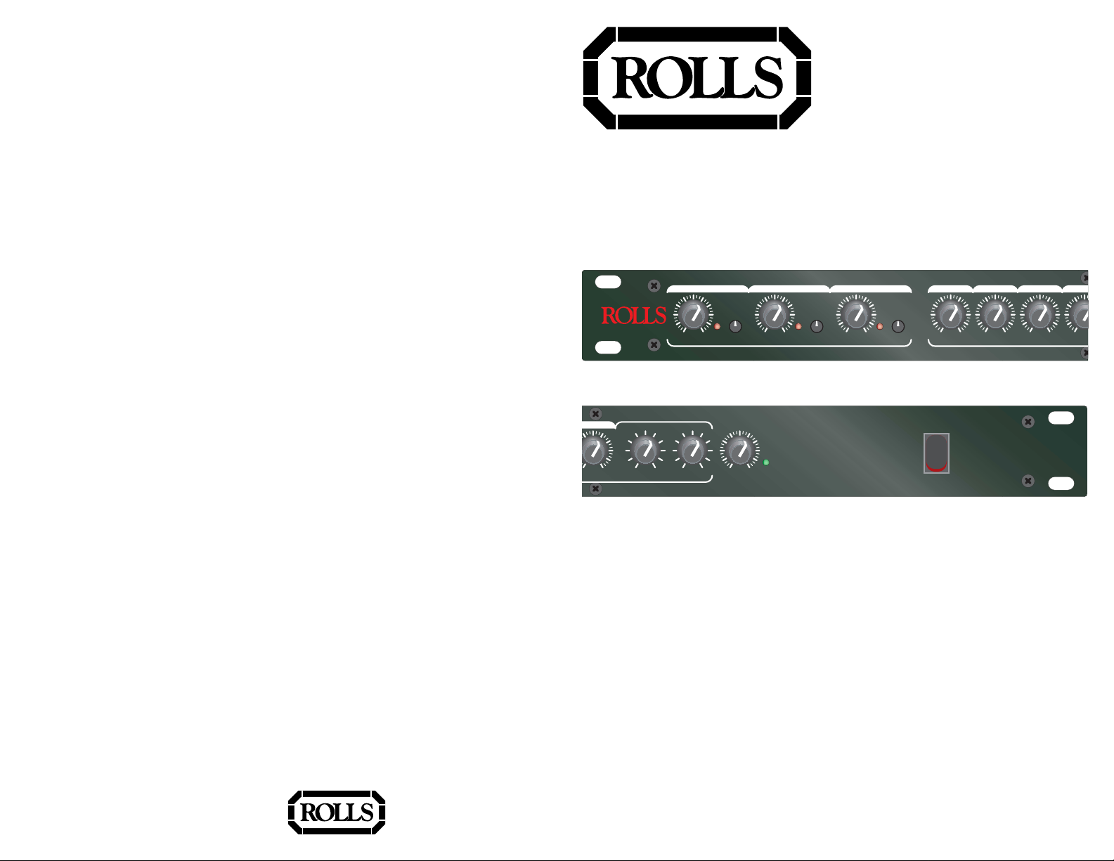
RM67
Mic/Source Mixer
MIC ONE MIC TWO MIC THREE 1 2 3 4
TONE TONE TONE
0 10
LEVEL
RM67
4
10
LEVEL
0 10
LEVEL
- + - +
BASS TREBLE
clip clip clip
0 10
LEVEL
MICROPHONE INPUTS SOURCE INPUTS
MASTER
LEVEL
0 10
MICROPHONE/SOURCE
MIXER
pwr
FEATURES
• Three XLR balanced inputs with phantom pow er
• Four stereo Source inputs
• Tone controls for each Microphone input
• Clip indicators for each Microphone input
• Bass and Treble controls for the Source inputs
• 1/4” input f or remote volume control
• RCA Record Out
• Master Output Level control
• 1/4” TRS balanced outputs
0 10
LEVEL
0 10
LEVEL
0 10
LEVEL
0
LEV
ROLLS CORPORATION
SALT LAKE CITY, UTAH
11/03
OWNERS MANUAL
Page 2
INTRODUCTION
Thank your for y our purchase of the Rolls RM67 Microphone/Source Mix er. The
RM67 is a single rack space audio mixer with three XLR inputs and f our stereo
RCA source inputs. Talkover features hav e been included on Mic 1 and Source 4
for paging and music priority functions.
NOTE: THIS MANUAL ASSUMES THE USER HAS A WORKING KNOWLEDGE
OF AUDIO ELECTRONICS, BALANCED AND UNBALANCED CONNECTIONS,
AND PROPER SIGNAL LEVEL SETTING.
INSPECTION
1. Unpac k and inspect the RM67 bo x and pac kage .
If obvious physical damage is noticed, contact the carrier immediately to make a
damage claim. We suggest saving the shipping carton and packing materials for
safely transporting the unit in the future.
2. Please visit our w ebsite at www.rolls.com and click on the Register Y our
Warranty Here b utton, or complete the Warranty Registration Card and return it to
the factory.
APPLICATIONS
Applications for the RM67 include aerobics studios, karoak e lounges, clubs and
restaurants, or audio visual applications. Its v ersatile inputs and outputs mak e it
an important problem solver in many audio situations.
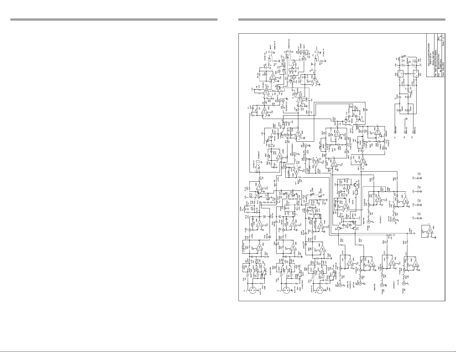
SCHEMATIC
TABLE OF CONTENTS
Introduction 1
Inspection 1
Applications 1
Table of Contents 1
Description 2
Connection 3
Operation 4
Specifications 5
Schematic 6
Warranty Back Cover
1 6
Page 3

SPECIFICATIONS
DESCRIPTION
Input Impedance: Mic: 600 Ohms XLR balanced
Line: 22K Ohms
22K
Ohms
Source:
gold plated RCA
Mic Insert: 22K Ohms 1/4" TS unbal.
Max Input Level: Mic: -14 dBV Mic level
+20 dB Line levl
Source: 24 dBV
Connectors: 3: XLR, 6: Stereo RCA, 3: 1/4" TRS, 1: 1/4” TS
Phantom Power: +12 VDC
Output Level: +17 dBV max
Output Impedance: 51 Ohms
Max Gain: Mic: 60 dB
Source: 26 dB
Tone Controls: +/-12 dB 100 Hz Bass
+/-12 dB 11kHz Treble
Nose Floor: - 80 dB, THD: <.025%, S/N Ratio: 96 dB
Size: 19" x 1.75" x 6" (48.3 x 4.5 x 15 cm)
Weight: 5 lbs. (2.3 kg)
FRONT PANEL
MASTER
MIC ONE MIC TWO MIC THREE 1 2 3 4
TONE TONE TONE
0 10
clip clip clip
LEVEL
MICROPHONE INPUTS SOURCE INPUTS
0 10
0 10
LEVEL
LEVEL
0 10
0 10
LEVEL
0 10
LEVEL
LEVEL
0 10
LEVEL
- + - +
BASS TREBLE
LEVEL
MICROPHONE/SOURCE
MIXER
pwr
0 10
RM67
Mic 1 - 3: Adjust the le v el of signal from the corresponding Mic Input.
clip 1 - 3: LED indicating overload in the channel. The LED lights 3dB below
clipping.
TONE 1 - 3: Adjusts the frequency content of the signal in the channel. When the
control is turned counter-clockwise, the high frequencies are cut, when the control
is turned clockwise, the low frequencies are cut.
Source 1 - 4: Adjust the v olume of input from the RCA Source Inputs.
Bass: Adjusts the low frequencies of the Source signals only.
Treble: Adjusts the high frequencies of the Source signals only.
Master Level: Adjusts the over all v olume of the RM67 Main Outputs.
pwr: LED indicating power is applied to the RM67 and the unit is on.
REAR PANEL
MIC
MIC
MIC
2
1
WARNING:
DO NOT EXPOSE THIS EQUIPMENT TO RAIN OR MOISTURE
NO USER SERVICABLE PARTS INSIDE.
RISQUE DE CHOC - NE PAS ENLEVER
PRIORITY
SPARE
L
R
RECORD
MUTE
SOURCE INPUTS
OUT
L
MIC
INSERT
R
3
mic/line mic/line mic/line
Mic 1 - 3: XLR inputs f or dynamic or condenser microphones, or balanced linelevel signals.
Mic/Line Switch: P ads the XLR Mic input by 30 dB when pressed in.
DIP SWITCH: Contains the small s witches for engaging Mic 1 - 3 phantom power ,
the priority (T alk Ov er) functions, and the Mono/Stereo select.
MIC INSERT: 1/4” TRS insert jack for adding external processing to the Mic
signals. Tip = send, ring = return.
SOURCE INPUTS: Stereo RCA jacks , Channels 1 - 4, for connection to stereo
sources such as AM/FM tuners, cassette players , cd players, or video players.
RECORD OUT: Stereo RCA jack s, contains all mix ed signals bef ore the Remote
V olume jack, and Master Le v el control.
SPARE: This RCA jack is not connected.
MUTE: RCA jac k for connection to a tip-to-g round muting circuit.
REMOTE VOLUME: 1/4” TS jack for connection to a remote potentiometer f or
master volume control. 20K Ohm audio taper potentiometer is recommended.
MAIN OUTPUTS: 1/4” TRS balanced Right and Left Outputs.
25
Page 4

CONNECTION
OPERATION
Connect low impedance microphones to the Mic inputs. If a paging microphone is
being used, connect it to Mic Input 1 so it may be used with the Talk Over function.
Connect source signals such as CD players , cassette pla yers or video players to
the RCA Source Inputs. If a juk ebox is being connected, and you want its signal to
mute the other source signals, connect it to Source input 4.
Remote V olume Control
To control the overall volume of the RM67 in a remote location, wire a 100K ohm
Linear Taper potentiometer to a 1/4” Tip-Ring-Sleev e plug as sho wn in Fig. 1.
Mic Insert
To connect a signal processor to the RM67 microphone signal(s), use an insert
plug, or cable wired as shown in Fig. 2.
Connect the Main Right and Left outputs to your power amplifiers. The RM67
output jacks will accommodate balanced or unbalanced connections. F or unbalanced operation use 1/4” Tip Sleeve jac ks , f or balanced operation use 1/4” Tip
Ring Sleeve jac ks. If a 1/4” TRS to XLR cable is needed, wire the Tip of the 1/4”
jack to pin 2 of the XLR, the Ring to pin 3, and the Sleev e to pin 1 or the shield.
Mute
To mute all audio, connect an RCA plug to your muting circuitry . When the tip is
shorted to the ground - all audio is muted.
DIP SWITCH SETTINGS
• If a microphone requires phantom power , mov e the Mic channel’s corresponding
PHAN DIP switch to the down position. This applies 12 v olts dc phantom po wer to
the indicated microphone.
• Talkover switch 1 (T.O. 1), when in the down position, all program material on all
inputs will be “duck ed” or muted when a signal is present at Mic 1.
This function is used for paging.
• Talkover s witch 2 (T.O. 2), when in the down position, Source 1,2, and 3 will be
“ducked” or muted b y the signals at Source 4.
This function is for jukebo x priority. With a jukebo x connected to Source input 4,
and the Talkover switch 2 on (do wn), the other Source input signals such as
background music, will be m uted and only the jukebox will be heard.
• The Mono/Stereo s witch selects the output mode . When the s witch is up , the unit
is in stereo mode. When the switch is down, the stereo signals are mixed to mono
and sent to both the Right and Left Main output jacks. Either jack can be used as
a mono output.
Adjust the Microphone levels f or maxim um input signal without clipping, and f or a
comfortable listening level. Adjust each Source level for a desired listening lev el.
Connect the RM67 to a properly grounded AC outlet.
100 K Ohm
Linear Taper
Potentiometer
Ring
Sleeve
Tip
Fig. 1
To Mic Insert
3 4
Fig. 2
 Loading...