

Page 1
LIMITED W ARRANTY
0
0 100 100 100 100 100 100 10
BALBAL
AUX
BAL
AUX
BAL
AUX
BAL
AUX
BAL
AUX
BAL
AUX
BAL
AUX
LEVELLEVELLEVELLEVEL
LEVEL
LEVELLEVEL
R L
10 0
CLIP
CLIP CLIP CLIP CLIP CLIP CLIP
R L
10 0
R L
10 0
R L
10 0
R L
10 0
R L
10 0
R L
10 0
R
1
2
3
45
6
7
This product is warranted to the original consumer purchaser to be free
from defects in materials and workmanship under normal installation, use and
service for a period of one (1) year from the date of purchase as shown on the
purchaser’s receipt.
The obligation of Rolls Corporation under this warranty shall be limited
to repair or replacement (at our option), during the warranty period of any part
which proves defective in material or workmanship under normal installation,
use and service, provided the product is returned to Rolls Corporation, TRANSPORTATION CHARGES PREPAID. Products returned to us or to an authorized
Service Center must be accompanied by a copy of the purchase receipt. In the
absence of such purchase receipt, the warranty period shall be one (1) year from
the date of manufacture.
This warranty shall be invalid if the product is damaged as a result of
defacement, misuse, abuse, neglect, accident, destruction or alteration of the
serial number, improper electrical voltages or currents, repair, alteration or
maintenance by any person or party other than our own service facility or an
authorized Service Center, or any use violative of instructions furnished by us.
This one-year warranty is in lieu of all expressed warranties, obligations
or liabilities. ANY IMPLIED WARRANTIES, OBLIGA TIONS, OR LIABILITIES, INCLUDING BUT NOT LIMITED TO THE IMPLIED WARRANTIES
OF MERCHANT ABILITY AND FITNESS FOR A PARTICULAR PURPOSE,
SHALL BE LIMITED IN DURATION TO THE ONE YEAR DURATION OF
THIS WRITTEN LIMITED WARRANTY. Some states do not allow limitations
on how long an implied warranty lasts, so the above limitation may not apply to
you.
IN NO EVENT SHALL WE BE LIABLE FOR ANY SPECIAL, INCIDENTAL OR CONSEQUENTIAL DAMAGES FOR BREACH OF THIS OR
ANY OTHER WARRANTY , EXPRESSED OR IMPLIED, WHATSOEVER.
Some states do not allow the exclusion or limitation of special, incidental or
consequential damages so the above limitation or exclusion may not apply to
you. This warranty gives you specific legal rights, and you may also have other
rights which vary from state to state.
ROLLS CORPORATION
SAL T LAKE CITY, UTAH
3/00
0 10
10 0
L
L
AUX
8
0 10
LEVELLEVEL
CLIP CLIP
R L
BAL
10 0
AUX
RM203
Stereo Line Mixer
910
0 10
R L
BAL
LEVEL
10 0
AUX
CLIP
0 10
TAPE IN
AUX RETURN
MASTER LEVEL
CLIP
0 100 10
HEADPHONE/
AUX OUT
RM203
OWNERS MANUAL
PWR
Page 2
INTRODUCTION
Thank your for your purchase of the Rolls RM203 Stereo Line Mixer. The RM203
is a line-level mix er f eaturing ten channels of stereo inputs , a Tape input and
output, and a mono auxiliary send and stereo return. Each channel has a signal
level control, a right/left balance control, an auxiliary lev el control, and a clip LED.
INSPECTION
1. Unpac k and inspect the RM203 bo x and pac kage .
Your RM203 was carefully packed at the factory in a protective carton. Nonetheless, be sure to examine the unit and the carton for any signs of damage that ma y
have occurred during shipping. If ob vious physical damage is noticed, contact the
carrier immediately to make a damage claim. We suggest saving the shipping
carton and packing materials for safely transporting the unit in the future.
2. Please complete the Warranty Registration Card and return it to the f actory.
FEA TURES
• 10 Stereo Inputs
• RCA Tape Inputs and Outputs
• Balanced 1/4” TRS Outputs
• Mono Auxiliary Send - Stereo Returns
• Clip Indication of each channel
RCAX4
R3
R2
J21A
C1
1K
10K
REC OUT
1
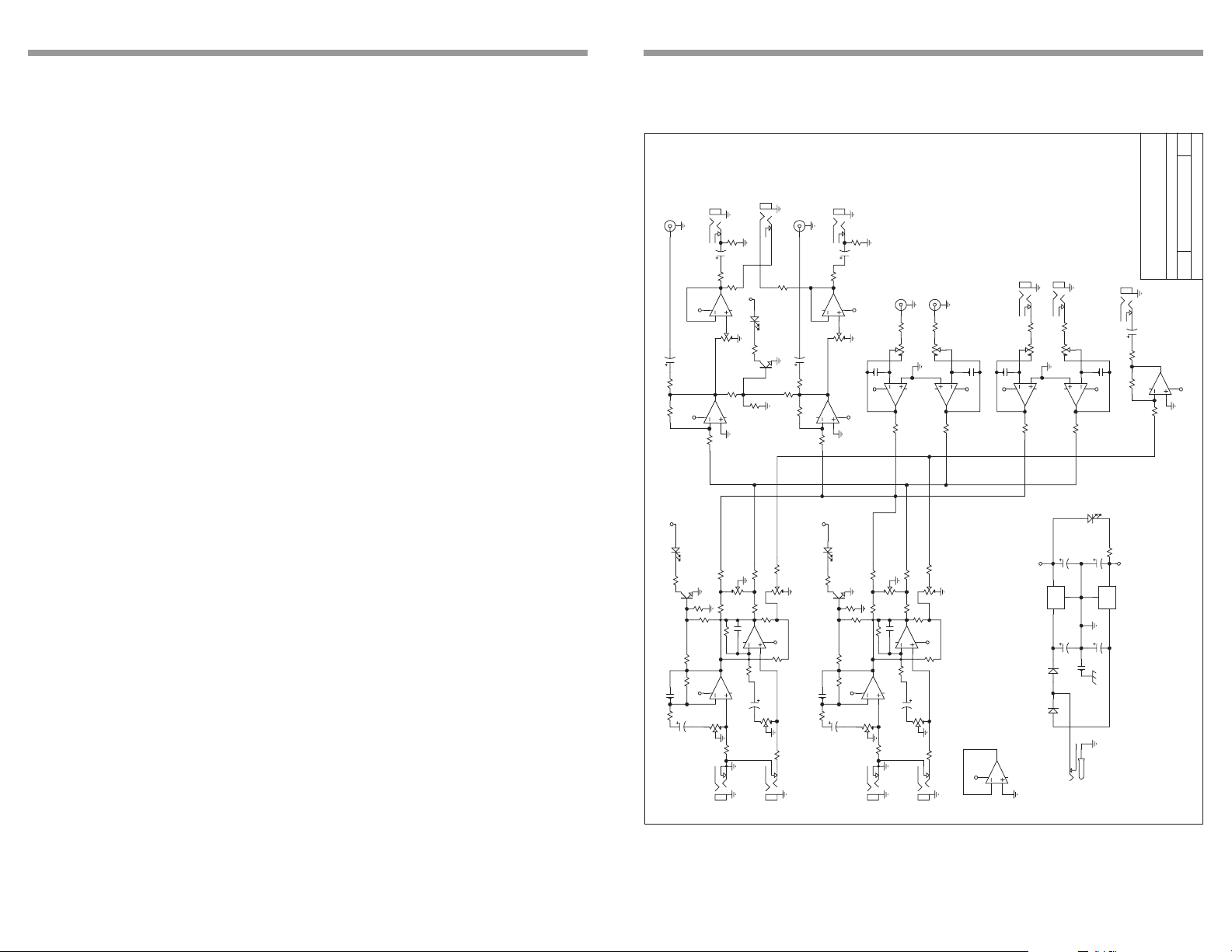
SCHEMATIC
126-Mar-2000
D
Rev:
1
Sheet of
REC OUT
J21B
RCAX4
J23
3
PHONE 1/4
C2
8
1U
8
VCC
R1
100
PHONE 1/4
R8
100K
J22
10U
R6
51
R7
100
7
VCC
OVLOAD
2
6
5
D1
LDRR
4560
U2B
1 3
R23
4.7K
P31A
P100K X2
7
R4
100K
R5
6
10K
5
4560
U1B
7
R15
100K
J24
PHONE 1/4
2
C4
10U
R14
51
R13
Q1
2N3904
C3
100K
R11
R10
10K
100
1
RCAX4
4
VEE
5
4560
2
3
U2A
P31B
1U
1K
R12
1
4560
2
3
R9
U1A
100
P100K X2
4
VEE
R16
4 6
2
C5
120PF
6
8
VCC
R30
REC IN
REC IN
J21D
RCAX4
J21C
4
10K
1 3
5
7
10K
P33A
P100K X2
4560
6
P100K X2
4560
P33B
8
5
R17
10K
5
C6
4 6
3
2
4
1
U3A
U3B
R27
10K
VEE
120PF
J25
PHONE 1/4
R18
AUX RETURN
2
C7
120PF
6
8
VCC
R29
J26
PHONE 1/4
R19
10K
1 3
5
7
4560
10K
P34A
P100K X2
P34B
P100K X2
5
C8
120PF
4 6
3
2
4
VEE
1
U4B
10K
U4A
R28
10K
4560
5143 South Main Street
Salt Lake City, UT 84107
ROLLS CORPORATION
J27
PHONE 1/4
C9
1U
AUX SEND
1K
R22
1
R21
10K
2
3
4560
U5A
R20
100
Document Number: RM203
KEYBOARD MIXER RM203
Rb
Date:
Title
Size:
4
VEE
• Balance control on each channel
• Headphone / Auxiliary Output
• External Power Supply included f or quieter operation
TABLE OF CONTENTS
Introduction 1
Inspection 1
Features 1
Table of Contents 1
Description
Front P anel 2
Rear Panel 2
Connection/Operation 3 - 4
Specifications 5
Schematic 6
Warranty Back cover
1
D101
C102
R102
R107
120PF
2K
VCC
LDRR
4.7K
R104
1U
C101
OVLOAD
Q101
2N3904
100K
47K
R103
8
VCC VCC
P1B
MONO/RIGHT
CHANNEL 1 OF 10
R109
10K
R106
100K
R105
P100K X2
PHONE 1/4
D4
LDSG
VCC
1
JAPDC
C13
10U
1000UF 16V
C11
4.7K
R24
VEE
3
O
G
U7
I
7912
2
C12
D201
OVLOAD
LDRR
P2
P100K
R117 10K
R116
4.7K
R113
7
6
5
J2
4.7K
BAL
P3
AUX
4.7K
4.7K
R115
R108
R114
1
10K
4
47K
C104
4560
5
4 6
VEE
120PF
2
3
2K
U101A
10K
R112
R111
4560
1U
C103
U101B
1 3
2
P1A
10K
R101
P100K X2
10K
R110
J1
PHONE 1/4
Q201
4.7K
R207
P100K
R204
100K
47K
R203
120PF
C202
2K
R202
1U
C201
LEFT
2N3904
R206
R205
8
VCC
P4B
P100K X2
MONO/RIGHT
R209
4.7K
10K
100K
R213
7
6
5
J4
PHONE 1/4
P5
P100K
R217 10K
R216 4.7K
BAL
P6
AUX
4.7K
4.7K
R215
R208
47K
C204
120PF
2
4560
R211
2K
4560
1U
5
C203
4 6
10K
R201
1
3
U201A
U201B
PHONE 1/4
P100K
R214
10K
4
VEE
10K
R212
P4A
P100K X2
1 3
2
10K
R210
LEFT
J3
VCC
7
8
6
5
4560
1UF
POWER
VCC
3
O
G
2
U6
I
7812
1
C10
1000UF 16V
503
D3
1N4001
C14
D2
1N4001
231
J28
U5B
6
Page 3

SPECIFICA TIONS
DESCRIPTION
Input Impedance: 10 k Ω unbal.
Output Impedance: 50 Ω bal
Max Input Level: +18 dBV
Phase Shift: < 10 deg. 20 Hz - 20 kHz
Connectors: 1/4" and RCA
Max Gain: 26 dB Line
26 dB Aux
S/N Ratio: >90 dB
THD < .003%
IMD (SMPTE) < .003%
Po wer 120 VAC 50-60 Hz, 15 W
Weight: 7 lbs (3kg)
Size: 19" x 1.75" x 6.5"
(48cm x 4.5cm x 17cm)
FRONT PANEL
2
1
CLIP CLIP CLIP CLIP CLIP CLIP
LEVELLEVEL
CLIP
10 0
R L
BAL
AUX
LEVEL
10 0
R L
R L
BAL
BAL
AUX
10 0
AUX
3
10 0
R L
BAL
45
R L
BAL
AUX
6
7
0 100 100 100 100 100 100 10
10 0
10 0
R L
BAL
AUX
AUX
0 10
R L
10 0
R L
BAL
BAL
AUX
8
CLIP CLIP
10 0
R L
AUX
BAL
0 10
LEVELLEVELLEVELLEVELLEVELLEVEL
10 0
AUX
910
0 10
0 10
CLIP
TAPE IN
LEVEL
10 0
R L
BAL
AUX
AUX RETURN
0 100 10
MASTER LEVEL
CLIP
HEADPHONE/
AUX OUT
PWR
RM203
Note: Channels One through Ten are identical.
Channel Section
Bal: Adjusts the relativ e le v el of the channel signal to the Right and Left outputs .
Aux: Adjusts the amount of signal sent to the Auxiliary Output
Level: Adjusts the ov erall signal le v el of the channel.
Clip: When lit, indicates clipping of e xcessiv e le v el into the channel.
Master Section
Tape In: Adjusts the amount of input signal from the rear panel Tape In jacks.
Aux Return: Controls the amount of signal receiv ed at the stereo A ux Return
jacks.
Master Level : Controls the overall output level of the RM203.
Headphone/Aux out: 1/4” TRS stereo jacks for monitoring the master right and left
signals, also may be used as an alternative stereo output f or connecting to
another stereo amplifier.
PWR: Indicates that the RM203 is connected to an A C outlet and is on.
REAR PANEL
MODEL RM203
POWER
12 VAC
MADE IN THE U.S.A.
S/N
203-
LEFT
RIGHT/MON
AUX
RIGHT
OUT
OUT
AUX RTN
SEND
LEFT
AUX RTN
TAPE
IN
OUT
MONO
R
RIGHT LEFT
L
10
MONO
RIGHT LEFT
9
MONO
RIGHT LEFT
8
MONO MONO
RIGHT LEFT
7
MONO
MONO
RIGHT LEFT6RIGHT LEFT5RIGHT LEFT4RIGHT LEFT3RIGHT LEFT
MONO MONO
MONO
2
RIGHT LEFT
1
Master Outputs
Right and Left Out: 1/4” TRS balanced main output jacks . For connection to an
amplifier, recording de vice or signal processor.
Right and Left Aux Return: 1/4” unbalanced jack, f or connection to the right and
left outputs of a signal processor, or the y ma y be used as auxiliary inputs.
Aux Send: 1/4” unbalanced jack, f or connection to a signal processor input such
as a multi-effects processor . This output may also be used as a monitor send for
connection to an amplifier and speakers for monitoring.
Tape Out: Stereo RCA jacks for connection to a stereo input de vice such as a
cassette player or CAT machine, for recording program material. Lev el is controlled by individual channel volumes.
Tape Inputs: Stereo RCA jacks for connection to a source such as a cassette
player or CD player .
Channel Inputs
Note: Channels One through Ten are identical.
Right / Left: 1/4” TS unbalanced jacks for connection to the right and left outputs of
a stereo instrument, or if nothing is plugged into the Left input, the signal connected to the Right input feeds both sides.
5
2
Page 4

CONNECTION / OPERA TION
The following three sections show e xamples for:
1. Connecting the inputs
2. Connecting the auxiliary section to a signal processor
3. Connecting the outputs.
INPUT CONNECTION EXAMPLE
RIGHT AND LEFT
OUTPUTS
MODEL RM203
POWER
12 VAC
MADE IN THE U.S.A.
203-
S/N
LEFT
AUX
RIGHT
OUT
OUT
SEND
RIGHT/MON
LEFT
AUX RTN
AUX RTN
MIDI CONTROL
TAPE
IN
OUT
MONO
R
RIGHT LEFT
L
MONO
MONO
RIGHT LEFT
10
MONO MONO
RIGHT LEFT8RIGHT LEFT7RIGHT LEFT6RIGHT LEFT5RIGHT LEFT4RIGHT LEFT3RIGHT LEFT2RIGHT LEFT
9
UP TO 9 TOTAL
SOUND MODULES
MONO
RIGHT AND LEFT OUTPUTS
FROM EACH SOUND MODULE
MONO
MONO MONO MONO
1
The RM203 is designed to receive line-lev el signals , thus a microphone or other
low input signal will be insufficient to drive the RM203 inputs. Connect the outputs
of each instrument or module via a 1/4” cable.
AUXILIARY SEND/STEREO RETURN CONNECTION EXAMPLE
CONNECTING THE OUTPUTS
MODEL RM203
S/N
RIGHT
POWER
OUT
12 VAC
MADE IN THE U.S.A.
4A 120V - 2A 230 V
MAINS POWER
WARNING
For continued prootection against
risk of fire, replace only with
same type and rating of fuse.
RISQUE DE CHOC - NE PAS ENLEVER
203-
LEFT
AUX
OUT
SEND
OUTPUT 2 OUTPUT 1
RIGHT/MON
AUX RTN
AUX RTN
TAPE
OUT
R
LEFT
L
-
OUTPUT 1
+
+
OUTPUT 2
-
IN
MONO
RIGHT LEFT
10
MONO
MONO
RIGHT LEFT9RIGHT LEFT8RIGHT LEFT7RIGHT LEFT6RIGHT LEFT5RIGHT LEFT4RIGHT LEFT3RIGHT LEFT2RIGHT LEFT
MONO MONO
MONO
SERIAL NUMBER
MADE IN U.S.A.
CHANNEL 2 INPUT CHANNEL 1 INPUT
MONO
MONO MONO MONO
BRIDGE NORMAL
CORPORATION
CAUTION
TO REDUCE THE RISK OF ELECTRIC
SHOCK DO NOT NOT REMOVE LID. NO
USER SERVICABLE PARTS INSIDE.
REFER SERVICING TO QUALIFIED
SERVICE PERSONNEL
WARNING:
To reduce the risk of electric
shock or fire do not expose
this device to rain or moisture.
1
MODEL RM203
203-
S/N
LEFT
POWER
12 VAC
MADE IN THE U.S.A.
RIGHT
OUT
RIGHT
AUX
OUT
AUX RTN
SEND
MULTI-EFFECTS PROCESSOR
LEFT
AUX RTN
TAPE
IN
OUT
MONO
R
RIGHT LEFT
L
10
MONO
MONO
RIGHT LEFT9RIGHT LEFT8RIGHT LEFT7RIGHT LEFT6RIGHT LEFT5RIGHT LEFT4RIGHT LEFT3RIGHT LEFT2RIGHT LEFT
MONO MONO
MONO
MONO
MONO MONO MONO
INPUT RIGHT
OUTPUTS
1
LEFT
Connect 1/4” unbalanced cables to the A ux Send to the Input of the signal processor, and connect each signal processor output to its corresponding A ux Return
jack. Set the “Mix” control on y our signal processor to 100% eff ect since the dry
portion of the signal is mixed in the RM203.
NOTE: The RM203 A ux Send jac k may also be connected to an amplifier, then to
speakers and used as a Monitor Send.
3
Connect the RM203 Right and Left Outputs to an amplifier via two balanced TRS
1/4” jacks (tw o TS unbalanced jacks will work as well).
4
 Loading...