

Page 1
LIMITED WARRANTY
T
T
This product is warranted to the original consumer purchaser to be free from
defects in materials and workmanship under normal installation, use and service for a
period of one (1) year from the date of purchase as shown on the purchaser’s receipt.
The obligation of Rolls Corporation under this warranty shall be limited to repair
or replacement (at our option), during the warranty period of any part which proves
defective in material or workmanship under normal installation, use and service, provided
the product is returned to Rolls Corporation, TRANSPORTA TION CHARGES PREPAID. Products returned to us or to an authorized Service Center must be accompanied by
a copy of the purchase receipt. In the absence of such purchase receipt, the warranty
period shall be one (1) year from the date of manufacture.
This warranty shall be invalid if the product is damaged as a result of defacement, misuse, abuse, neglect, accident, destruction or alteration of the serial number,
improper electrical voltages or currents, repair, alteration or maintenance by any person or
party other than our own service facility or an authorized Service Center, or any use
RA62
Stereo Headphone Amplifier
OUT
VOLUME
OUT
VOLUME
OUT
VOLUME
OUT
VOLUME
OUT
OU
VOLUME
violative of instructions furnished by us.
This one-year warranty is in lieu of all expressed warranties, obligations or
liabilities. ANY IMPLIED WARRANTIES, OBLIGATIONS, OR LIABILITIES,
INCLUDING BUT NOT LIMITED TO THE IMPLIED WARRANTIES OF MERCHANT ABILITY AND FITNESS FOR A PARTICULAR PURPOSE, SHALL BE
LIMITED IN DURATION TO THE ONE YEAR DURATION OF THIS WRITTEN
LIMITED WARRANTY. Some states do not allow limitations on how long an implied
warranty lasts, so the above limitation may not apply to you.
IN NO EVENT SHALL WE BE LIABLE FOR ANY SPECIAL, INCIDENTAL
OR CONSEQUENTIAL DAMAGES FOR BREACH OF THIS OR ANY OTHER
WARRANTY, EXPRESSED OR IMPLIED, WHATSOEVER. Some states do not allow
the exclusion or limitation of special, incidental or consequential damages so the above
limitation or exclusion may not apply to you. This warranty gives you specific legal
rights, and you may also have other rights which vary from state to state.
T
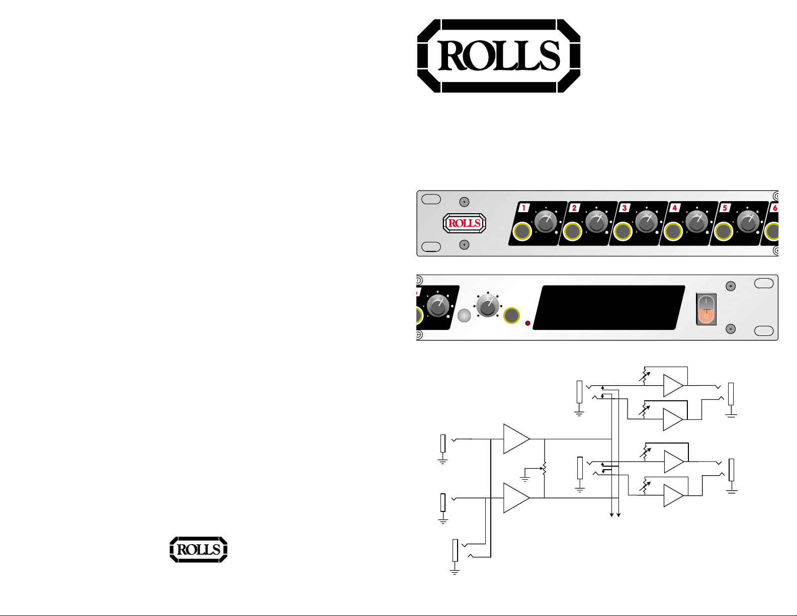
VOLUME
RIGHT
INPUT
LEFT
INPUT
FRONT PANEL
STEREO INPUT
MONO
STEREO
PAN
STEREO
INPUT
R
L
HEADPHONE
AMPLIFIER
PWR
INSERT
PAN
INSERT
TO CHANNELS
3 THROUGH 6
RA62
L
R
L
R
CHANNEL ONE
HEADPHONE OUT
CHANNEL TWO
HEADPHONE OU
ROLLS CORPORATION
SAL T LAKE CITY, UT AH
5/00
OWNERS MANUAL
Page 2

TABLE OF CONTENTS
SPECIFICATIONS
Table of Contents 1
Introduction 2
Features 2
Inspection 2
Description
Front P anel 3
Rear Panel 3
Connection 4
Schematic 5
Specifications 6
Warranty Back Cover
Input Impedance: 100K Ω unbalanced
Max Input Level: +18 dBV
Input Connectors: 1/4" TRS stereo , R & L 1/4" unbalanced
R & L 1/4" unbalanced Aux. inputs
6: 1/4" TRS insert jacks.
Outputs: 6: 1/4" TRS Stereo jacks
Max Gain: 20 dB/Channel
Max Output Power: up to 300 mWatt/Channel
Frequency Response: DC - 30 kHz
S/N Ratio: 90 dB
THD: <.008%
IMD: <.008%
Po we r 120 VAC 50-60 Hz, 15 VA
Weight: 7 lbs (3KG)
Size: 19" x 1.75" x 6.5" (48cm x 4.5cm x 17cm)
1
6
Page 3

SCHEMATIC
J 1 7
PHONE 1/4
PHONE 1/4
R 7 1 4 1 0 K
J 1 2
P C 1 / 4
1 0 K
R 4 0 7
2
P 4 A
P 1 0 0 K X 2
1 3
C 7
1 2 0 P F
6
5
8
VCC
U 4 B
4 5 6 0
7
3 0
R 4 0 4
Q 1 4
VCC
2 N 2 9 0 7
VDD
Q 1 3
M P S A 0 6
5 1
R 4 0 1
J 4
P H O N E 1 / 4
J 8
P C 1 / 4
INTRODUCTION
129-Mar-1999
D 9
L D S G
P O W E R
R57
4.7K
VCC
J 1 6
R 7 1 1
J 1 5
RIGHT IN
PHONE 1/4
1 0 K
R 7 0 1
R 7 1 3 1 0 K
2
3
U 7 A
4 5 6 0
1
1 0 K
R 7 0 5
1 0 K
R 7 0 6
6
5
8
VCC
U 8 B
4 7 K
4 5 6 0
7
C 1 3
1 0 U
J 1 0
L E F T I N
PHONE 1/4
1 0 0 K
R 7 1 6
4
VDD
P 7
P 1 0 0 K
P A N
R 7 1 0
1 0 K
D P D T
S W 1 B
3
6
5
1
4
M O N O / S T E R E O
J 1 3
P C 1 / 4
J 7
F R O N T I N
P H O N E 1 / 4
1 0 K
R 7 0 2
6
5
R 7 1 5
1 0 0 K
8
VCC
U 7 B
4 5 6 0
7
1 0 K
R 7 0 8
1 0 K
R 7 0 7
R 7 0 9
1 0 K
S W 1 A
D P D T
2
3
2
4
VDD
U 8 A
4 5 6 0
1
C 1 6
1 0 U
2200UF
C 1 5
C 1 8
D 2
D 1
1 N 4 0 0 1
D 3
1 N 4 0 0 1
D 4
T 1
M C I 4 0 7 5 0 2 4
4 7 K
R 7 1 2
VDD
2200UF
C 1 4
5 0 3
1 N 4 0 0 1
1 N 4 0 0 1
S W ?
2
S P S T A C M
1 2
J 1 4
P C 1 / 4
1 3
A C 1
A C P L U G
C
Rev:
1
Sheet of
RA62.SCH
5143 South Main Street
Salt Lake City, UT 84107
ROLLS CORPORATION
HEADPHONE AMPLIFIER RA62
Rb
Date:
Title
Size: Document Number:
Thank you for y our purchase of the Rolls RA62 Stereo Headphone Amplifier .The
RA62HA is a six-channel headphone amplifier for high quality audio monitoring. It
is intended for sound reinforcement, studio, choir, and other applications where
high channel to size ratio is desirable . Since the MONO/STEREO switch is after
the pan control, it will mix 2 MONO signals and their balance can be adjusted with
the Pan control. Up to six individual monitor mixes may be listened to via the rear
panel TRS stereo insert jacks. The RA62HA has an FR4 double sided circuit
board and painted steel chassis. It has six 1/4" stereo headphone outputs, one 1/
4" TRS stereo input located on the front panel. Right and Left 1/4" Input jacks, and
six 1/4" Insert jacks are located on the rear panel. There are two Auxiliary Inputs
(right and left) located on the rear panel. Each channel has a Volume control,
panning and balance is controlled via the Pan control located on the front panel,
and the unit features a MONO/STEREO switch.
FEATURES
• 6 Headphone Outputs with Level Controls
1 0 K
1 0 K
1 0 K
R 4 0 8
5
P 4 B
P 1 0 0 K X 2
4 6
C 8
1 2 0 P F
3
2
4
VDD
U 4 A
4 5 6 0
1
3 0
R 4 0 3
Q 1 5
M P S A 0 6
VCC
5 1
R 4 0 2
VDD
Q 1 6
2 N 2 9 0 7
C H A N N E L 4
1 0 K
R 5 0 7
2
1 3
C 9
1 2 0 P F
6
5
8
U 5 B
VCC
4 5 6 0
7
3 0
R 5 0 4
Q 1 8
VCC
2 N 2 9 0 7
Q 1 7
M P S A 0 6
5 1
R 5 0 1
P 5 0 8
P 5 A
5
P 1 0 0 K X 2
P 5 B
P 1 0 0 K X 2
4 6
C 1 0
1 2 0 P F
3
2
4
VDD
U 5 A
4 5 6 0
1
3 0
R 5 0 3
2 N 2 9 0 7
Q 2 0
Q 1 9
M P S A 0 6
VCC
VDD
J 5
P H O N E 1 / 4
J 9
P C 1 / 4
VDD
5 1
R 5 0 2
C H A N N E L 5
1 0 K
R 6 0 7
2
P 6 A
1 3
C 1 1
1 2 0 P F
6
5
8
VCC
U 6 B
4 5 6 0
7
3 0
R 6 0 4
Q 2 2
VCC
2 N 2 9 0 7
Q 2 1
M P S A 0 6
5 1
R 6 0 1
J 1 1
P C 1 / 4
R 6 0 8
P 1 0 0 K X 2
VDD
J 6
5
P 6 B
P 1 0 0 K X 2
4 6
C 1 2
1 2 0 P F
3
2
4
VDD
U 6 A
4 5 6 0
1
3 0
R 6 0 3
Q 2 3
Q 2 4
2 N 2 9 0 7
M P S A 0 6
VCC
R 6 0 2
P H O N E 1 / 4
VDD
5 1
C H A N N E L 6
• 6 TRS Stereo Insert jacks for separate use of each channel
• Up to 500 mW output per jack - it's loud
• Stereo/Mono Switch - allows mixing 2 mono signals
• Front and rear panel input jac ks
• DC to 30 kHz response for accurate sound reproduction
INSPECTION
1. Unpac k and inspect the RA62 bo x and pac kage .
If obvious physical damage is noticed, contact the carrier immediately to make a
damage claim. W e suggest sa ving the shipping carton and packing materials for
safely transporting the unit in the future.
2. Please complete the Warranty Registration Card and return it to the factory.
1 0 K
1 0 K
R 1 0 7
2
1 3
C 1
1 2 0 P F
6
5
8
VCC
U 1 B
4 5 6 0
7
3 0
R 1 0 4
Q 2
VCC
2 N 2 9 0 7
Q 1
M P S A 0 6
5 1
R 1 0 1
5
R 1 0 8
P 1 A
5
P 1 0 0 K X 2
P 1 B
P 1 0 0 K X 2
4 6
C 2
1 2 0 P F
3
2
4
VDD
U 1 A
4 5 6 0
1
3 0
R 1 0 3
Q 4
2 N 2 9 0 7
Q 3
M P S A 0 6
VCC
VDD
5 1
R 1 0 2
J 1
P H O N E 1 / 4
C H A N N E L 1
1 0 K
R 2 0 7
2
P 2 A
1 3
C 3
1 2 0 P F
6
5
8
VCC
U 2 B
4 5 6 0
7
3 0
R 2 0 4
2 N 2 9 0 7
VDD
Q 6
VCC
Q 5
M P S A 0 6
5 1
R 2 0 1
1 0 K
R 2 0 8
5
P 1 0 0 K X 2
P 2 B
P 1 0 0 K X 2
4 6
C 4
1 2 0 P F
3
2
4
VDD
U 2 A
4 5 6 0
1
3 0
R 2 0 3
Q 8
Q 7
M P S A 0 6
VCC
VDD
5 1
R 2 0 2
J 2
P H O N E 1 / 4
C H A N N E L 2
1 0 K
R 3 0 7
2
P 3 A
1 3
C 5
1 2 0 P F
6
5
8
VCC
U 3 B
4 5 6 0
7
3 0
R 3 0 4
2 N 2 9 0 7
VDD
VCC
Q 1 0
Q 9
M P S A 0 6
R 3 0 1
1 0 K
R 3 0 8
5
P 1 0 0 K X 2
P 3 B
P 1 0 0 K X 2
4 6
C 6
1 2 0 P F
3
2
4
VDD
U 3 A
4 5 6 0
1
3 0
R 3 0 3
Q 1 1
2 N 2 9 0 7
VDD
5 1
J 3
Q 1 2
M P S A 0 6
VCC
P H O N E 1 / 4
2 N 2 9 0 7
VDD
5 1
R 3 0 2
C H A N N E L 3
2
Page 4

DESCRIPTION
CONNECTION
FRONT PANEL
PAN
STEREO
OUT
OUT
OUT
OUT
VOLUME
VOLUME
VOLUME
OUT
OUT
VOLUME
VOLUME
VOLUME
MONO
STEREO
INPUT
PWR
HEADPHONE
AMPLIFIER
RA62
Note: Descriptions for Channel One through Channel Six are identical.
OUT 1 - 6 : 1/4” Tip-Ring-Slee v e jac k for connection to a standard pair of head-
phones.
VOLUME 1 - 6: Controls the amount of output signal from the indicated channel.
MONO/STEREO SWITCH: When this switch is pressed in, the Right and Left
channels are summed together providing a mono output signal.
PAN: Controls the relative amount of signal sent to the Right and Left output
channels.
STEREO IN: 1/4” TRS input jack which paralells the rear panel Right and Left
input jacks.
POWER LED: Indicates that the RA62 is connected to the po wer supply and is
on.
REAR PANEL
62-
120 VAC
50/60 Hz 15 VA
SERIAL NUMBER
MODEL RA62
WARNING:
DO NOT EXPOSE THIS EQUIPMENT TO RAIN OR MOISTURE.
TO REDUCE THE RISK OF ELECTRIC SHOCK DO NOT NOT REMOVE BACK.
MADE IN U.S.A.
NO USER SERVICABLE PARTS INSIDE. REFER SERVICING TO QUALIFIED SERVICE PERSONNEL
CAUTION
RISK OF ELECTRIC SHOCK
DO NOT OPEN
MAIN INPUT
LEFT
RIGHT
RISQUE DE CHOC - NE PAS ENLEVER
AUX INPUT
LEFT
INSERT 2
INSERT 5
INSERT 4
INSERT 3
INSERT 6
RIGHT
INSERT 1
NRTL /C
120 VAC INPUT: Connects to a properly grounded AC outlet.
MAIN INPUT: 1/4” TRS jacks f or connecting to the desired Right and Left prog ram
material.
AUX INPUT: Additional 1/4” unbalanced inputs - for use in the event
Note: The description for the Channel Inserts pertains to all six channels.
CHANNEL INSERTS:
Connect the AC cord to a properly grounded ac outlet.
Determine which input configuration you will use; either discreet right/left, TRS
stereo, or mono .
For a discreet right/left input configuration, connect a 1/4” TS plug containing the
“Right” portion of the stereo signal to the Right Main Input. Connect a 1/4” TS plug
containing the “Left” portion of the stereo signal to the Left Input.
For a TRS stereo input configur ation, connect a Tip-Ring-Slee v e stereo plug into
the front panel STEREO IN input. This cable may come from a mix er’s headphone
output for example.
To send a mono signal to the RA62, connect a 1/4” Tip-Sleeve plug into either the
Right or Left input and press in the front panel MONO/STEREO switch. This mono
signal will be fed to both the right and left sides of the headphone outputs.
The Aux Inputs are connected in the same manner as the discreet right/left input
configuration listed above .
INSERTS
The inserts have been provided so you can directly access each headphone
output with its own program material.
The inserts
require
Tip-Ring-Slee v e connectors, with right and left signals on the
tip and ring respectively. If you use a TS mono plug - you will only hear sound out
of one side.
When these insert jacks are used, the main Right/Stereo and Left/Mono, as well
as the Aux Inputs - are disconnected. Only the stereo signals sent to the Insert
jacks go to that corresponding output.
CAUTION: Plugging a mono 1/4” TS plug into the Headphone
Outputs may cause permanent damage to the unit because
one side would be shorted to ground.
Nev er plug a mono plug
into any of the Headphone Outputs.
Tip
Ring
Sleeve
(ground)
3
4
 Loading...