

Page 1
PT102
PHASE TESTER
Transmitter and Receiver
MIC
LINE
-
PHASE
OUT OF
+
IN
PHASE
IN
RECEIVER
PHASE TESTER
PT102r
BATTERY
INPUT
ON
LEVEL
PWR
Owners Manual
PT102 Phase Tester
• Check the phase integrity of any micro
phone or audio system.
• Transmitter features a speaker and line
level 1/4" output
• Receiver features a microphone and line
level 1/4" input.
• Battery operation
Rolls Corporation
Salt Lake City, UT
2/04
Page 2

INTRODUCTION
Thank you for y our purchase of the PT102 Phase Tester. The PT102 consists
of two units, a transmitter and receiv er. The PT102 transmitter creates a pulse
that is sent through an audio system. The receiver then picks up the signal at
various intervals in the system, and indicates whether or not the system is in
or out of phase.
The PT102t transmits a positive-going pulse via a speaker, or a 1/4" unbalanced jack. The PT102t speaker is placed near a microphone which ma y be
connected to the PT102r receiver or to an audio system.
Plugging into the 1/4" LINE IN jack on the receiver disables the mic.
When testing a microphone it is
speaker
INSPECTION
1. Unpac k and inspect the PT102 box and package.
If obvious physical damage is noticed, contact the carrier immediately to
make a damage claim. W e suggest sa ving the shipping carton and packing
materials for safely transporting the unit in the future.
2. Please complete the Warranty Registration Card and return it to the f actory.
TABLE OF CONTENTS
Introduction: 1
Inspection: 1
Table of Contents: 1
Description: 2
Operation: 3, 4
Schematic: 5
Warranty: 6
directly
at at 90 degree angle.
very important
that the mic face the PT102t
LIMITED WARRANTY
This product is warranted to the original consumer purchaser to be free from
defects in materials and workmanship under normal installation, use and service for a
period of one (1) year from the date of purchase as shown on the purchaser’s receipt.
The obligation of Rolls Corporation under this warranty shall be limited to
repair or replacement (at our option), during the warranty period of any part which
proves defective in material or workmanship under normal installation, use and
service, provided the product is returned to Rolls Corporation, TRANSPORT ATION
CHARGES PREPAID. Products returned to us or to an authorized Service Center
must be accompanied by a copy of the purchase receipt. In the absence of such
purchase receipt, the warranty period shall be one (1) year from the date of manufacture.
This warranty shall be invalid if the product is damaged as a result of
defacement, misuse, abuse, neglect, accident, destruction or alteration of the serial
number, improper electrical voltages or currents, repair , alteration or maintenance by
any person or party other than our own service facility or an authorized Service
Center, or any use violative of instructions furnished by us.
This one-year warranty is in lieu of all expressed warranties, obligations or
liabilities. ANY IMPLIED W ARRANTIES, OBLIGATIONS, OR LIABILITIES,
INCLUDING BUT NOT LIMITED TO THE IMPLIED WARRANTIES OF
MERCHANTABILITY AND FITNESS FOR A PARTICULAR PURPOSE, SHALL
BE LIMITED IN DURATION TO THE ONE YEAR DURATION OF THIS
WRITTEN LIMITED WARRANTY. Some states do not allow limitations on how
long an implied warranty lasts, so the above limitation may not apply to you.
IN NO EVENT SHALL WE BE LIABLE FOR ANY SPECIAL, INCIDENTAL OR CONSEQUENTIAL DAMAGES FOR BREACH OF THIS OR ANY
OTHER WARRANTY, EXPRESSED OR IMPLIED, WHATSOEVER. Some states
do not allow the exclusion or limitation of special, incidental or consequential
damages so the above limitation or exclusion may not apply to you. This warranty
gives you specific legal rights, and you may also have other rights which vary from
state to state.
1 6
Page 3

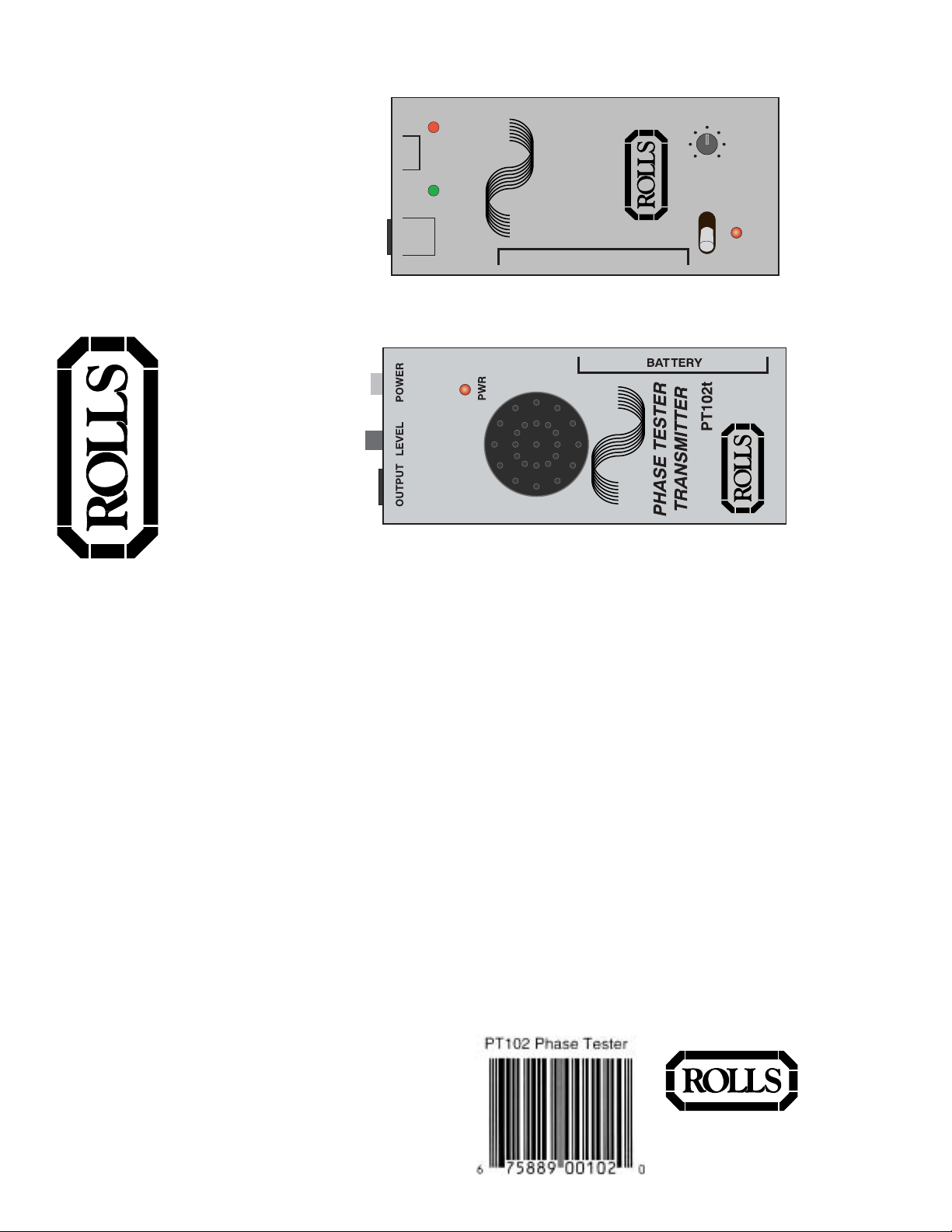
SCHEMATIC
Transmitter
POWER: Push switch - turns the PT102t on and off.
LEVEL: Adjusts the amount of test pulse le v el sent out the
OUTPUT jack.
OUTPUT: 1/4" unbalanced jack for connection to the input of
the device to be tested.
PWR: LED indicating pow er is properly connected to the
PT102t and the POWER switch is in the on position.
Speaker: (Not labeled) Creates an audible pulse . To be
placed in front of a microphone which may then be tested,
or connected to a system being tested. NOTE: The speaker
is always ticking when the tr ansmitter is on.
BATTERY: Remova ble door , 9 Volt battery clip.
Receiver
LINE IN:1/4" unbalanced jack for connection to line le v el
devices carrying the pulse signal from the transmitter and
system being tested.
MIC: Small condenser microphone on the top of the
PT102r. Picks up the audio pulse from a speaker.
IN PHASE: Green LED indicating positiv e-going or inphase signals.
OUT OF PHASE: Red LED indicating negativ e-going or
out of phase signals.
BATTERY: Remova ble door , 9 Volt battery clip.
POWER SWITCH: When s witched to the ON position, turns
on the PT102r.
PWR: LED indicating that the PT102r is on.
DESCRIPTION
+
IN
PHASE
RECEIVER
PT102r
ON
MIC
OUT OF
PHASE
INPUT
LEVEL
-
LINE
IN
PHASE TESTER
BATTERY
PWR
25
Page 4

OPERATION
The PT102 will check the phase of any audio signal source. There are ,
howev er, some considerations that
must
be observed. F or balanced applications we use pin 2 as the "hot" or positive connection. So an XLR connector is
Pin 1 ground, pin 2 hot, pin 3 neutral or negative.
Because of the nature of audio signals, the reciever microphone m ust be held
as close to 90 degrees to the sound source to get an accurate reading. See
the example below.
MICROPHONE PHASE
OUTPUT LEVEL POWER
PWR
o
90
PHASE TESTER
TRANSMITTER
Pin 1
BATTERY
PT102t
Pin 2
Pin 3
There are a couple of options to check the phase of a microphone. If the mic
is dynamic, it may be connected directly to the receiv er via an XLR f emale to
1/4" TS unbalanced male cable . The tip of the 1/4" plug must be wired to pin 2
of the XLR plug, and pin 1 and 3 should be wired together and connected to
ground. Switch the Power switch on the PT102r ON. The mic may then be
held close to the transmitter to check the phase of the microphone.
If the microphone is a condenser type, the mic must first be powered by either
its own internal battery, or b y a phantom pow er adapter. Rolls PB23, PB223,
or PB224 are all correctly phased phantom power adapters, and may be used
to power condenser microphones. The output of the condenser mic or phantom power adapter may be plugged into the PT102r receiv er using the
unbalanced cable mentioned above , and the mic is tested the same wa y.
AUDIO SYSTEM PHASE
To check the phase integrity of your audio system, connect the 1/4" OUTPUT
of the PT102t to the input of the system to be checked. Or, as in the example
above, hold the tr ansmitter up to a microphone that is connected to the
system.
The PT102r receiver may then be connected in v arious places throughout
3
your audio system to check the phase integrity.
You may wish to begin at either the microphone, or line input source. Then
check each connection before it enters the ne xt de vice . An example connection is shown below. Note that the PT102r receiv er may also be placed in front
of the speakers to check the final phase. Just ensure the PT102r is directly
facing the speaker .
Signal Processor
Signal Processor
Auxiliary Send
Auxiliary Return
Audio system
Line
Input
OUTPUT LEVEL POWER
PHASE TESTER
TRANSMITTER
PT102t
PWR
Mic
Input
BATTERY
Output
= insertion points
LINE
IN
PHASE
PHASE TESTER
RECEIVER
PT102r
BATTERY
ON
PWR
MIC
-
+
OUT OF
IN
PHASE
INPUT
LEVEL
4
 Loading...