

Page 1
MX902
Professional Compact Mixer
MIC 1
TRIM
+6
dB
LINE 1
-6 dB
12.5 k
-15 +15
HIGH
60
-15 +15
LOW
+50
MIC 2
TRIM
+6
dB
LINE 2
-6 dB
12.5 k
-15 +15
HIGH
60
-15 +15
LOW
+50
MIC 3
TRIM
+6
dB
LINE 3
-6 dB
12.5 k
-15 +15
HIGH
60
-15 +15
LOW
+50
PHANTOM
PWR
4/LEFT/MONO
-15 +15
-15 +15
AUX 1
SEND
5/RIGHT
12.5 k
HIGH
60
LOW
AUX 2
SEND
6/LEFT/MONO 8/LEFT/MONO
7/RIGHT 9/RIGHT
12.5 k
-15 +15
HIGH
60
-15 +15
LOW
LEFT OUT
12.5 k
-15 +15
HIGH
60
-15 +15
LOW
RIGHT OUT
AUX 1
RET LEFT/MONO
AUX 1
RET RIGHT
CLIP
R
L
R
AUX 2 RET
L
MX902
PWR
12 - 18 VDC
POWER
+
-
0 10
AUX 2
0 10
AUX 1
L R
PAN
-OO +1 5
LEVEL
1
0 10
AUX 2
0 10
AUX 1
L R
PAN
-OO +1 5
LEVEL
2
0 10
AUX 2
AUX 1
L R
PAN
-OO +1 5
LEVEL
3 4/5
0 10
AUX 2
AUX 1
L R
BAL
-OO +1 5
LEVEL
0 10
AUX 2
0 100 100 10
AUX 1
L R
BAL
-OO +1 5
LEVEL
6/7
0 10
AUX 2
0 10
AUX 1
L R
BAL
-OO +1 5
LEVEL
8/9
0 10
AUX 2
RETURN
AUX 1
0 10
RETURN
-OO +15
LEVEL
HDPHN
-OO +1 5
LEVEL
MAIN
HDPHN
OUT
OWNERS MANUAL
Page 2

Thank you for purchasing the ROLLS MX902 Prof essional Mixer. This unit is designed and manufactured to provide
years of useful service. Please read the following manual carefully .
The MX902 is a compact mixer for small mixing applications . It has an external power supply adding to it's already
quiet and transparent operation. An important feature of the MX902 is it's ability to operate on +12 to +16 Volts DC .
This means that the unit is perfect for mobile sound reinf orcement where a car or camer a battery may be the only
source of power . The MX902 is in a durable steel chassis, and ma y be optionally r ac kmounted.
FEATURES
• Runs on +12 Volts DC - perfect for mobile operation
• 3 XLR Mic Inputs each with trim control
• 9 Total 1/4" unbalanced inputs, RCA Tape Inputs
• +24 Volt Phantom Power
• 2-band EQ
• 2 Auxiliary Sends; 1 pre-fade, 1 post-fade
• 2 Stereo Auxiliary Returns
• Balanced 1/4" Outputs
• Tape Outputs are pre-Master fader
• Tape Inputs share the Aux 1 bus
• Headphone Output w/level control
INSPECTION
1. Unpac k and inspect the MX902 bo x and pac kage .
If obvious physical damage is noticed, contact the carrier immediately to make a damage claim. We suggest saving the
shipping carton and packing materials for safely transporting the unit in the future.
2. Please complete the Warranty Registration Card and return it to the factory .
TABLE OF CONTENTS
Introduction ................................................................................................................................ 1
Features ................................................................................................................................
Inspection ................................................................................................................................
Front P anel Description ................................................................................................................... 2
Channel Descriptions ...................................................................................................................
The EQ Section...................................................................................................................
The Auxiliary Section .........................................................................................................
Pan/Bal Controls .................................................................................................................
Level Control ...................................................................................................................
Master Section ...................................................................................................................
Auxiliary Return Controls ....................................................................................................
Headphone ...................................................................................................................
Master Level ...................................................................................................................
Jack P anel Description ................................................................................................................... 3
Channel Inputs ...................................................................................................................
Trim Controls ...................................................................................................................
Main Right and Left Outputs ...............................................................................................
Auxiliary Outputs and Inputs ...............................................................................................
Phantom Po wering ..............................................................................................................
Operation ................................................................................................................... 4
Signal Processor Connection ........................................................................................................... 5
Live Example ...................................................................................................................
Schematic ................................................................................................................... 6
Specifications and W arranty ............................................................................................................. Rear Cover
1
Page 3
Front Panel
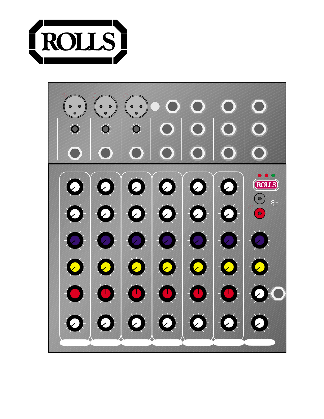
CHANNEL DESCRIPTIONS
HIGH: Boosts or cuts the 12.5 kHz or high frequency portion of the signal.
LOW: Boosts or cuts the 60 Hz or low frequency portion of the signal.
AUX 2: Controls the amount of post-fader signal that is sent to the Aux 2 bus
and output.
AUX 1: Controls the amount of pre-fader signal that is sent to the Aux 1 bus
and output.
12.5 k
-15 +15
HIGH
60
-15 +15
LOW
12.5 k
-15 +15
HIGH
60
-15 +15
LOW
PAN: Varies the amount of relative signal sent from Channels’ 1 through 3 to
the Main Level control.
BAL: Varies the amount of stereo signal from channels 5/6 through 8/9 to the
Main Level control.
LEVEL: Controls the overall output signal level of the channel.
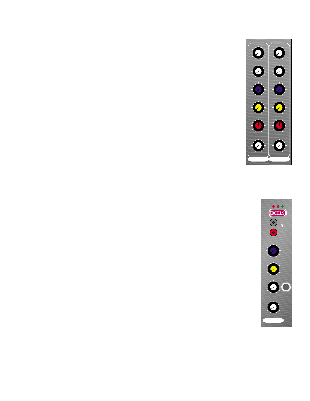
MASTER DESCRIPTIONS
AUX 2 RETURN: Controls the amount of input signal from the RCA Aux 2 Return
jacks.
AUX 1 RETURN: Controls the amount of input signal from the Aux 1 Right and Left
Return jacks.
HEADPHONE LEVEL: Controls the amount of level of signal from the Headphone
Output.
HEADPHONE OUTPUT: 1/4” TRS stereo jack for connection to stereo headphones.
NOTE: Do not use a mono 1/4” TS plug in this jack. Doing so may result
in serious damage to the MX902.
MAIN LEVEL: Controls the amount of signal sent to the Right/Left output jacks.
0 10
AUX 2
AUX 1
L R
PAN
-OO +15
LEVEL
3 4/5
0 10
0 100 10
L R
-OO +15
CLIP
L
L
AUX 2 RET
R
MX902
0 10
AUX 2
RETURN
AUX 1
0 10
RETURN
-OO +15
LEVEL
HDPHN
AUX 2
AUX 1
BAL
LEVEL
R
PWR
12 - 18 VDC
POWER
HDPHN
OUT
+
-
-OO +15
LEVEL
MAIN
2
Page 4

Jack Panel Description
TRIM
+6
LINE 1
-6 dB
MIC 1
dB
+50
TRIM
LINE 2
-6 dB
+6
MIC 2
dB
+50
TRIM
+6
LINE 3
-6 dB
MIC 3
dB
+50
PHANTOM
PWR
AUX 1
SEND
4/LEFT/MONO 6/LEFT/MONO 8/LEFT/MONO
5/RIGHT
AUX 2
SEND
7/RIGHT 9/RIGHT
LEFT OUT
RIGHT OUT
AUX 1
RET LEFT/MONO
AUX 1
RET RIGHT
Channels 1 through 3
MIC INPUT: XLR input jack for microphone level or balanced signals.
TRIM: Controls the amount of input gain from +6 to +50 dB.
LINE: 1/4” unbalanced input for instrument of line level signals.
PHANTOM POWER SWITCH: Engages the +24 volts of phantom power, used to power condenser microphones.
Channels 4/5 through 8/9
LEFT: 1/4” unbalanced input for instrument or line level signals.
RIGHT: 1/4” unbalanced input for instrument or line level signals.
Master
AUX 1 and 2 SEND: 1/4” unbalanced jacks for sending out the signals present on the Aux 1 and 2
buses.
RIGHT OUT: 1/4” TRS balanced main right output.
LEFT OUT: 1/4” TRS balanced main left output.
AUX 1 RET. RIGHT and LEFT: 1/4” unbalanced jacks for receiving stereo signals sent from the
Aux 1 bus (usually through an effects processor).
AUX 2 RET. Stereo RCA jacks for receiving stereo signals send from the Aux 2 bus, or may be
used as an auxiliary stereo source input such as a CD or cassette player.
Side Panel
12 - 18 VDC: For connection to a sleeve positive, DC power adapter.
POWER Switch: Applies power to the MX902 when connected to a proper power source.
3
Page 5

MIC 1
MIC 2
MIC 3
PHANTOM
PWR
AUX 1
SEND
AUX 2
SEND
LEFT OUT
RIGHT OUT
+6
LINE 1
-6 dB
4/LEFT/MONO 6/LEFT/MONO 8/LEFT/MONO
+50
+50
dB
LINE 2
-6 dB
+50
+6
dB
+6
LINE 3
-6 dB
dB
5/RIGHT
7/RIGHT 9/RIGHT
from
to Effects Input
Left Output
AUX 1
RET LEFT/MONO
AUX 1
RET RIGHT
from
Right Output
STEREO EFFECTS DEVICE
SIGNAL PROCESSOR CONNECTION
Use Aux 1 Output to connect to the Input of your signal processor which may be an echo unit, a
reverb, or multi effects unit. Aux 1 is used because the signal is taken after the channel fader
which is a typical setup for a signal processor. The right and left outputs of the processor are then
connected to the Aux 1 Right and Left Return jacks. The level of signal going into the signal processor is controlled by the Aux 1 control on each individual MX902 channel, and the signal
processor’s input level control. The level of signal going back into the MX902 is controlled by Aux 1
Return Level control on the MX902 front panel, and by the signal processor’s output level control.
4
Page 6

LIVE CONNECTION EXAMPLE
The diagram shown below is a possible connection scheme for a live application. Connect instruments and microphones to the appropriate input jacks. If condenser microphones requir ing phantom power are being used, press the Phantom Power switch in. Aux 2 is used as a monitor output
because the signal is taken before the channel fader - this is typically a monitor send. Aux 1 may
be connected to a signal processor as shown on page 4.
Connect the Right and Left main outputs to the main amplification system. If the system being
used is mono, either MX902 Right or Left output may be used.
LINE 1
-6 dB
LINE 2
-6 dB
MIC 2
+50
+6
dB
LINE 3
-6 dB
MIC 3
PHANTOM
+50
+6
dB
AUX 1
SEND
PWR
4/LEFT/MONO 6/LEFT/MONO 8/LEFT/MONO
5/RIGHT
AUX 2
SEND LEFT OUT
7/RIGHT 9/RIGHT
RIGHT OUT
AUX 1
RET LEFT/MONO
AUX 1
RET RIGHT
MIC 1
+50
+6
dB
MONITOR AMPLIFIER
MAINS AMPLIFIER
VOLUME 2
VOLUME 1
P
OWER AMPLIFIER RA2100B
5
Page 7

SCHEMATIC
Sheet: 1 of 1
ROLLS CORPORATION
5968 South 350 West
Salt Lake City, UT 84107
Title: MX902 12v Mic/Line Mixer
Size:
Date: 2-Aug-2000
Rb
+12V
+12V
R I G H T
L E F T
A U X 1
V O L U M E
P A N
V O L U M E
C H A N N E L S 1 T O 3
A U X 2
A U X 1 O U T
+12V
6 O H z
1 2 K H z
+12V
+12V
+12V
-12V
C H 1
+12V
A U X 1 O U T
A U X 2 O U T
T A P E I N
R I G H T
R I G H T
+12V
+24V
A U X 2 I N
1 O F 3
O V L D
+12V
+12V
L E F T
V O L U M E C H A N N E L S 1 T O 3
+12V
1 O F 3
+12V
B A L
+12V
A U X 1
V O L U M E
L E F T I N
R I G H T I N
A U X 2
C H A N N E L S 4 T O 6
-12V
+12V
R I G H T
+12V
H E A D P H O N E
VCC
BIAS
BIAS
BIAS
BIAS
BIAS
BIAS
BIAS
BIAS
BIAS
BIAS
BIAS
BIAS
BIAS
BIAS
BIAS
BIAS
BIAS
BIAS
BIAS
BIAS
BIAS
+12v
+12V
+24V
R 1 1 6
3 3 K
R 1 2 7
1 M
R 1 2 8
4 . 7 K
R 1 2 9
4 . 7 K
R 1 3 0
4 . 7 K
R 1 3 1
4 . 7 K
C 1 1 1
1 0 U
C 1 1 3
. 0 4 7
R 1 1 8 3 3 K
P 1 0 6
P 1 0 0 K
R 1 3 2
1 0 K
R 1
1 0 0
R 2
1 0 K
R 1 2 1 0 K
R 1 5
3 3 K
R 1 8
5 1
R 5 7
1 K
R 5 8
1 0 0 K
1 K
R 6 2
1 0 0 K
1 K
C 2
1 U
C 7
1 U
C 9
1 0 U
13
2
P 1 A
C 1 3
2 5 P F
C 1 7
2 7 P F
4 6
5
P 4 B
1 3
2
R 1 1 2
1 0 K
C 1 0 3
4 7 0 P F
C 1 0 4
4 7 0 P F
C 1 0 5
1 U
C 1 0 6
4 7 0 U
C 1 0 7
2 7 P F
C 1 0 9
2 7 P F
1 2
3
J 1 0 1
R 1 0 1
6 . 8 K
R 1 0 7
3 0
R 1 1 0
2 K
R 1 1 1
2 K
R 1 0 8
1 0 0
R 1 1 3
1 0 K
R 1 0 9
4 . 7 K
R 2 0
5 1
1 0 K
R 4 7
1 0 K
1 K
Q 1 0 1
2 N 5 0 8 7
Q 1 0 2
2 N 5 0 8 7
C 6
2 7 P F
R 1 7
3 3 K
R 1 1 9 1 0 K
R 5 5
1 0 K
R 5 3
1 0 K
C 1 8
1 U
R 6 0
1 0 0 K
C 2 0
1 U
R 6 4
1 0 0 K
R 5
3 3 K
J 5
P H O N E 1 / 4
R 2 0
5 1
R 8
5 1
C 1 2 7 P F
R 1 6
4 . 7 K
R 6 4 . 7 K
R 1 1 7
3 . 3 K
J 1 0 2
P H O N E 1 / 4
P 1 0 7
C 1 0 K
P 1 0 5
P 1 0 0 K
1 3
2
P 1 0 1 A
P 1 0 4
P 1 0 0 K
P 1 0 3
P 1 0 0 K
P 1 0 2
P 1 0 0 K
46
5
P 1 B
4 6
5
P 3 B
1 3
2
P 3 A
J 3
J 1
P H O N E 1 / 4
J 2
P H O N E 1 / 4
1
2
3
S W 1 A
D P D T
R 6 7
4 . 7 K
R 7 4
1 0 0 K
R 7 5
4 . 7 K
C 1 9
2 7 P F
C 2 5
1 K U F
C 2 7
1 U
D 1
L D S G
231
J 9
J A P D C
J 6 0 2
P H O N E 1 / 4
J 6 0 1
P H O N E 1 / 4
R 6 3 2
3 3 K
R 6 3 3
2 2 K
R 6 3 4
2 2 K
R 6 3 5
2 2 K
4 6
5
P 6 0 1 B
C 6 1 6
1 0 U
R 6 3 6
3 . 3 K
R 6 3 7
3 3 K
46
5
P 6 0 6 B
C 6 2 1
. 0 0 1
R 6 4 6
1 M
R 6 4 12 2 K
46
5
P 6 0 5 B
C 6 1 8
. 0 4 7
R 6 4 7
4 . 7 K
R 6 4 9
4 . 7 K
R 6 5 0
1 0 K
P 6 0 4
P 1 0 0 K
R 6 4 8
4 . 7 K
R 6 5 1
1 0 K
P 6 0 3
P 1 0 0 K
R 6 2 6
4 . 7 K
R 6 2 7
4 . 7 K
P 6 0 2
P 1 0 0 K
C 6 1 2
. 0 4 7
13
2
P 6 0 5 A
1 3
2
P 6 0 1 A
13
2
P 6 0 6 A
R 6 1 4
3 3 K
R 1 1 4
1 0 K
R 3 7
3 3 K
R 4 2 2 K
13
2
46
5
3
2
1
4
4 5 6 0
5
6
7
8
4 5 6 0
R 4 0
1 0
C 6 2 3
4 7 U
1 0
D 2
L D R R
R 7 0
1 0 K
D 3
L D R R
R 6 8
4 . 7 K
C 5
1 0 U
6
5
7
8
U 6 0 2 B
4 5 6 0
2
3
1
4
U 6 0 2 A
4 5 6 0
2
3
1
4
U 6 0 3 A
4 5 6 0
6
5
7
8
U 4 0 1 B
4 5 6 0
5
6
7
8
U 1 0 1 B
4 5 6 0
2
3
1
4
U 1 0 2 A
4 5 6 0
2
3
1
4
4 5 6 0
6
5
7
8
U 2 B
4 5 6 0
2
3
1
4
U 2 A
4 5 6 0
6
5
7
8
U 3 B
4 5 6 0
2
3
1
4
4 5 6 0
6
5
7
8
4 5 6 0
3
2
1
4
U 3 A
4 5 6 0
6
5
7
8
U 5 B
4 5 6 0
3
2
1
4
4 5 6 0
6
5
7
8
U 4 B
4 5 6 0
C 6 2 8
1 0 U
C R 3
1 N 4 1 4 8
C 2 1
1 U
C 2 4
1 U
C R 7
C 6 2 5
1 U
C 2 3
1 U
123
S W 2 A
D P D T
R 6 5 8
1 0 0 K
R 3
1 0 0 K
C R 4
1 N 4 1 4 8
R 6 5 7
1 0 0 K
2
3
1
4
U 2 0 1 A
4 5 6 0
C 6 3 5
1 U
C 6 3 6
1 U
C 6 3 7
1 U
C 4
1 0 U
R 7 3 3 K
R 6 2 4
1 M
C 6 3 3
1 U
C 6 3 4
1 U
2
3
1
4
U 4 0 1 A
4 5 6 0
R 7 1
4 7 K
C 2 9
1 2 0 P F
R 1 2 0
1 0 K
R 1 2 4
1 0 K
R 6 4 4
1 0 K
R 6 4 5
1 0 K
R 6 3 8
1 0 K
R 6 4 0
1 0 K
R 6 1 7
1 0 K
R 6 1 8
1 0 K
R 6 2 2
1 0 K
R 6 2 3
1 0 K
R 1 0 6
4 . 7 K
R 6 5 6
1 0 0 K
R 6 5 2
1 0 0 K
R 6 9
4 7 K
C 6 1 0
1 0 U
R 6 1 5
3 . 3 K
R 6 1 6
3 3 K
6
5
7
8
U 6 0 3 B
4 5 6 0
R 6 2 5
4 . 7 K
R 1 0 3
1 0 K
R 1 0 4
1 0 K
C 1 0 2
1 U
C R 5
1 N 4 0 0 1
Q 1 0 7
M P S A 0 5
J 6
P H O N E 1 / 4
C 6 3 8
1 U
R 3 8
2 K
6
5
7
8
U 1 0 2 B
4 5 6 0
C 1 1 0
1 0 U
C 1 0 8
1 0 2
C 1 1 2
2 7 P F
C 6 1 1
2 7 P F
C 6 1 7
2 7 P F
2 7 P F
C 1 6
2 7 P F
C 1 5
2 7 P F
C 3
5 0 3
C 1 1 8
1 U
R 1 0 2
6 . 8 K
C 1 1 7
1 U
C 1 0 1
1 U
R 1 2 6
1 0 K
R 1 2 2
1 0 K
R 1 2 3 2 2 K
C 1 1 6 . 0 0 1
C 6 1 5 . 0 0 1
R 6 1 9 2 2 K
Q 1 0 8
2 N 3 9 0 4
C 2 6
4 7 U
Q 1 0 3
2 N 3 9 0 4
Q 1 0 4
2 N 3 9 0 4
J 7
P H O N E 1 / 4
C 6 2 4
J 8 A
R C A P C
J 8 B
R C A P C
D o c u m e n t N u m b e r :
M X 9 0 2 .s c h
R e v : A
U 6 A
R 4 3
3 3 K
C 1 2
1 0 U
R 4 4
R 3 9
3 3 K
R 4 1
3 3 K
P 2 B
U 6 B
P 2 A
R 6 1
R 1 1
1 0 0
U 4 A
P H O N E 1 / 4
U 5 A
C 1 0
1 0 U
P H O N E 1 / 4
L E F T
R 5 2
1 0 K
L E F T
U 1 B
P 4 A
R 5 1
1 0 K
C 1 4
U 1 A
R 5 4
1 0 K
R 5 6
1 0 K
C R 8
1 N 4 1 4 8
1 N 4 1 4 8
6
Page 8

SPECIFICATIONS
Input Impedance: 10kW bal./unbal.
Output Impedance: 50W
Max Input Level: +4 dBm XLR, +10 dBV 1/4”
Output Level: +12 dBV max
Max Gain: 80 dB XLR, 74 dB 1/4”
Phantom Power: +24 Volts DC
EQ Centers: High: 12.5kHz
Low: 60Hz
S/N Ratio: 128 dB
THD: <.003%
IMD (SMPTE): <.003%
CMRR: 52 dB (typ.) Mic
Size: 9” x 10” x 1.64”
Weight: 3 lbs.
Power: +12 VDC, 150 mA
LIMITED WARRANTY
This product is warranted to the original consumer purchaser to be free from defects in materials and
workmanship under normal installation, use and service for a period of one (1) year from the date of purchase as shown on the purchaser’s receipt.
The obligation of Rolls Corporation under this warranty shall be limited to repair or replacement (at
our option), during the warranty period of any part which proves defective in material or workmanship under
normal installation, use and service, provided the product is returned to Rolls Corporation, TRANSPORTATION CHARGES PREPAID. Products returned to us or to an authorized Service Center must be accompanied by a copy of the purchase receipt. In the absence of such purchase receipt, the warranty period shall be
one (1) year from the date of manufacture.
This warranty shall be invalid if the product is damaged as a result of defacement, misuse, abuse,
neglect, accident, destruction or alteration of the serial number, improper electrical voltages or currents,
repair, alteration or maintenance by any person or party other than our own service facility or an authorized
Service Center, or any use violative of instructions furnished by us.
This one-year warranty is in lieu of all expressed warranties, obligations or liabilities. ANY IMPLIED WARRANTIES, OBLIGATIONS, OR LIABILITIES, INCLUDING BUT NOT LIMITED TO THE
IMPLIED WARRANTIES OF MERCHANT ABILITY AND FITNESS FOR A PARTICULAR PURPOSE,
SHALL BE LIMITED IN DURATION TO THE ONE YEAR DURATION OF THIS WRITTEN LIMITED
WARRANTY. Some states do not allow limitations on how long an implied warranty lasts, so the above
limitation may not apply to you.
IN NO EVENT SHALL WE BE LIABLE FOR ANY SPECIAL, INCIDENTAL OR CONSEQUENTIAL DAMAGES FOR BREACH OF THIS OR ANY OTHER WARRANTY, EXPRESSED OR IMPLIED, WHATSOEVER. Some states do not allow the exclusion or limitation of special, incidental or
consequential damages so the above limitation or exclusion may not apply to you. This warranty gives you
specific legal rights, and you may also have other rights which vary from state to state.
ROLLS CORPORATION
SALT LAKE CITY , UTAH
4/96
 Loading...