

Page 1
For warranty registration please visit the rolls web site at www.rolls.com.
MX34c LiveMix
HEADSET
MIC
1/8”
c
ROLLS CORPORATION
SALT LAKE CITY, UTAH
04/10
CHANNEL 1 CHANNEL 2
INPUTS
PHANTOM POWER
ON=DOWN
OFF=UP
AUX
IN
STEREO
OUT
OUTPUT LEVEL
MIC
LINE
POWER
12 VDC
+
-
MADE IN USA
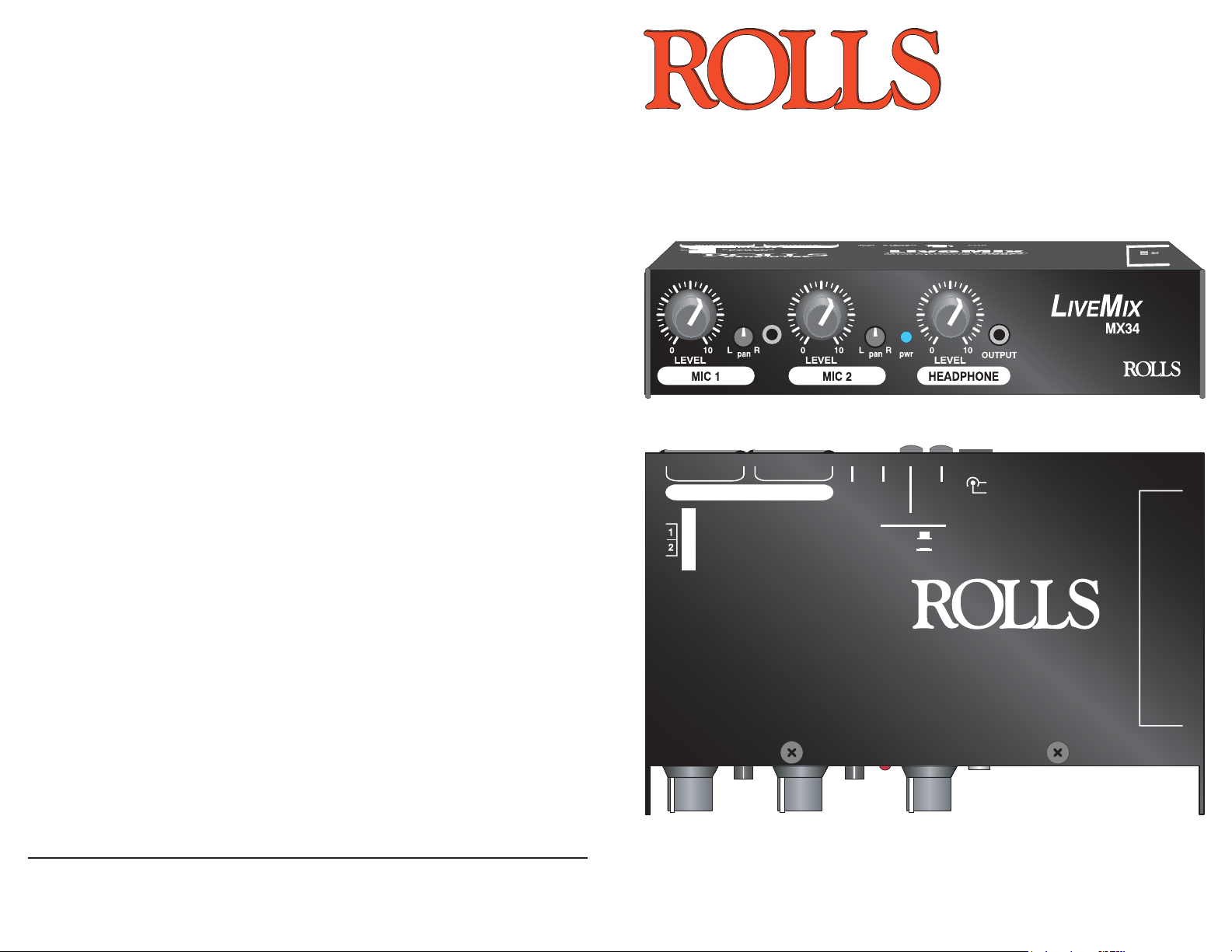
LiveMix
Two Channel Stereo
Microphone Mixer/
Headset Mixer
MX34c
www.rolls.com
QUICK START
OPERATION GUIDE
9V x 2
BATTERIES
Page 2

INTRODUCTION
SPECIFICATIONS
Thank you for purchasing the new MX34c LiveMix - two channel microphone mixer.
Although having many uses, this little mixer was originally designed with the video camera
operator in mind. It’s handy shoulder strap, easy-access microphone Level and Pan
controls, and smart Input/Output jack placement make the MX34c ideal for the live recording enthusiast. Two 9 volt alkaline batteries ensure adequate signal strength as well as
phantom power for your favorite condenser microphone.
Please review this manual carefully as it contains important information regarding the
proper use of this product.
INSPECTION
1. Unpack and Inspect the MX34c package
Your MX34c was carefully packed at the factory in a protective carton. Nonetheless, be
sure to examine the unit and the carton for any signs of damage that may have occurred
during shipping. If obvious physical damage is noticed, contact the carrier immediately to
make a damage claim. We suggest saving the shipping carton and packing materials for
safely transporting the unit in the future.
2. Please visit our web site at www.rolls.com, click on the Register Your Warranty Here
text and follow the instructions to register your MX34c.
TABLE OF CONTENTS
INTRODUCTION 1
INSPECTION 1
TABLE OF CONTENTS 1
Input Impedance: mic - 600 Ohms or greater XLR
aux - 47K stereo 3.5mm
Output Impedance: 50 Ohms
THD + Noise: .02%
S/N Ratio: 110 dB
Frequency Response: 20 Hz - 30 kHz (+0 / -1 dB)
Max Output Level: + 14 dB
Max Input Level: +20 dB
Max Gain: +70 dB
Batteries: 2 X 9V Alkaline
Current Draw: 30 mA
Phantom Power: +18 VDC
Input Connectors: 2 Female XLR, 1/8” (3.5mm)
DC Power Jack: (5.5 X 2.1 mm tip negative)
Output connectors: 3.5mm stereo main out
3.5mm Headphone
Size: 6.3”w x 3.7”d x 1.4” h
Weight: 1 lbs.
DESCRIPTION 2
Front Panel
Rear Panel
Battery Installation
Phantom Power
CONNECTION 3
A note on wiring a mono signal to the stereo AUX IN
OPERATION 4
SCHEMATIC 5
SPECIFICATIONS 6
WARRANTY BACK COVER
1
6
Page 3

SCHEMATIC
DESCRIPTION
FRONT PANEL
HEADSET
MIC
1/8”
c
MIC1 and MIC2
LEVEL: Adjusts the amount of signal of the indicated Microphone channel.
PAN: Adjusts the relative level of signal from the channel to the Right/Left Output.
pwr: When lit, indicates that the MX34c is on. A dim light indicates low battery
voltage.
HEADPHONE
LEVEL: Adjusts the amount of signal from the Headphone Output.
OUTPUT: 1/8” (3.5mm) jack containing the Headphone Output signal.
REAR PANEL
OUTPUT LEVEL
MIC
LINE
STEREO
12 VDC
POWER
+
AUX
OUT
IN
INPUTS: 1 - 2: XLR balanced inputs for connection to any standard dynamic or condenser
microphone. The input circuitry has a very wide input range and can accommodate almost
any (mic to line) level signal.
AUX IN: Tip-Ring-Sleeve stereo 1/8” (3.5mm) jack for connecting to another line-level
stereo signal source.
STEREO OUT: Tip-Ring-Sleeve stereo 1/8” (3.5mm) jack for connection to a camera or
other stereo input.
MIC/LINE OUTPUT LEVEL: Button for switching the stereo output level to MIC or LINE.
Follow the silk screening of the unit for switch
orientation.
POWER: Button applies power to the MX34c.
12 VDC jack: For connection to the Rolls PS27
12VDC power supply.
BATTERY INSTALLATION: To replace the 9 V alkaline batteries, fi rst carefully press in
and up on the door to release the battery compartment. It then slides out and you can
replace the battery. Remember to replace both batteries at the same time.
CHANNEL
2
INPUTS
CHANNEL
1
PHANTOM POWER: Follow the silk screening of the MX34c to activate phantom power to
the input XLR’s.
5
2
Page 4

CONNECTION
T
OPERATION
Connect microphones to the MX34c via balanced XLR cables.
Stereo auxiliary sources such as the output from another mixer, AM/FM tuners,
CD Players, and MP3 players may be connected to the AUX IN via a stereo 1/8”
(3.5mm) Tip-Ring-Sleeve plug.
Connect the STEREO OUT to the Input of your recording device also using a
stereo 1/8” (3.5mm) Tip-Ring-Sleeve plug.
If you wish to use AC power for the MX34c, connect the Rolls PS27 12VDC
power supply.
OUTPUT LEVEL
MIC
To camera input
or other mic or
line level stereo
input
12 VDC
+
POWER
LINE
STEREO
AUX
OUT
IN
CHANNEL
2
INPUTS
CHANNEL
1
Once your MX34c is properly connected, apply power by pressing in the POWER
button on the rear panel. The blue pwr LED on the front panel should light.
If you are using condenser type microphones, apply the phantom power to the
desired channels. Test the microphone levels by speaking into the microphones
at a normal operating volume, and adjust the Mic Level controls until you achieve
desired levels. Adjust each Pan control to place the signal in the stereo fi eld.
Adjust the Headphone Level control for a comfortable listening volume.
For best results, we recommend recording a couple of test runs to ensure you
have proper levels set.
HEADSET
MIC
1/8”
c
When the signal becomes weak and distorted, or the pwr LED dims, the batteries will need replacing. See page 2; Battery Installation for details.
Connect STEREO headphones
or earphones to the 1/8” (3.5mm)
HEADPHONE OUTPUT located
on the MX34c front panel.
NOTE: ON CONNECTING A WIRELESS MIC TO THE AUX INPUT
DO NOT CONNECT A MONO PLUG TO
THE AUX IN OR STEREO OUTPUT. DOING SO WILL RESULT IN SIGNAL LOSS
IP RING SLEEVE
STEREO PLUG
OR DAMAGE TO THE MX34c.
If you need to connect a MONO signal (like
the output of a wireless microphone) to the
AUX IN of the MX34c, you will need to make or
purchase a MONO TO STEREO cable.Shown
here is a diagram of this cable’s wiring.
3 4
Tip and Ring are wired together,
then connected to the Tip of the
Mono Plug.
MONO PLUG
 Loading...