

Page 1
LIMITED WARRANTY
This product is warranted to the original consumer purchaser to be free
from defects in materials and workmanship under normal installation, use and
service for a period of one (1) year from the date of purchase as shown on the
purchaserís receipt.
The obligation of Rolls Corporation under this warranty shall be limited
to repair or replacement (at our option), during the warranty period of any part
which proves defective in material or workmanship under normal installation,
use and service, provided the product is returned to Rolls Corporation, TRANS-
PORTATION CHARGES PREPAID. Products returned to us or to an authorized
Service Center must be accompanied by a copy of the purchase receipt. In the
absence of such purchase receipt, the warranty period shall be one (1) year from
the date of manufacture.
This warranty shall be invalid if the product is damaged as a result of
defacement, misuse, abuse, neglect, accident, destruction or alteration of the
serial number, improper electrical voltages or currents, repair, alteration or
maintenance by any person or party other than our own service facility or an
authorized Service Center, or any use violative of instructions furnished by us.
This one-year warranty is in lieu of all expressed warranties, obligations
or liabilities. ANY IMPLIED WARRANTIES, OBLIGATIONS, OR LIABILI-
TIES, INCLUDING BUT NOT LIMITED TO THE IMPLIED WARRANTIES
OF MERCHANTABILITY AND FITNESS FOR A PARTICULAR PURPOSE,
SHALL BE LIMITED IN DURATION TO THE ONE YEAR DURATION OF
THIS WRITTEN LIMITED WARRANTY. Some states do not allow limitations
on how long an implied warranty lasts, so the above limitation may not apply to
you.
IN NO EVENT SHALL WE BE LIABLE FOR ANY SPECIAL, INCI-
DENTAL OR CONSEQUENTIAL DAMAGES FOR BREACH OF THIS OR
ANY OTHER WARRANTY, EXPRESSED OR IMPLIED, WHATSOEVER.
Some states do not allow the exclusion or limitation of special, incidental or
consequential damages so the above limitation or exclusion may not apply to
you. This warranty gives you specific legal rights, and you may also have other
rights which vary from state to state.
MX34 LiveMix
ROLLS CORPORATION
SALT LAKE CITY, UTAH
11/04
OWNERS MANUAL
Page 2

INTRODUCTION
SPECIFICATIONS
Thank you for purchasing the new MX34 LiveMix - two channel microphone mixer.
Although having many uses, this little mixer was originally designed with the video
camera operator in mind. Itís handy shoulder strap, easy-access microphone Level and
Pan controls, and smart Input/Output jack placement make the MX34 ideal for the live
recording enthusiast. Two 9 volt alkaline batteries ensure adequate signal strength as well
as phantom power for your favorite condenser microphone.
Please review this manual carefully as it contains important information regarding the
proper use of this product.
INSPECTION
1. Unpack and Inspect the MX34 package
Your MX34 was carefully packed at the factory in a protective carton. Nonetheless, be
sure to examine the unit and the carton for any signs of damage that may have occurred
during shipping. If obvious physical damage is noticed, contact the carrier immediately to
make a damage claim. We suggest saving the shipping carton and packing materials for
safely transporting the unit in the future.
2. Please visit our website at www.rolls.com, click on the Register Your Warranty Here
text and follow the instructions to register your MX34.
TABLE OF CONTENTS
INTRODUCTION 1
INSPECTION 1
TABLE OF CONTENTS 1
Input Impedance: mic - 600 Ohms or greater XLR
aux - 47K stereo 3.5mm
Output Impedance: 50 Ohms
THD + Noise: .02%
S/N Ratio: 110 dB
Frequency Response: 20 Hz - 30 kHz (+0 / -1 dB)
Max Output Level: + 14 dB
Max Input Level: +20 dB
Max Gain: +70 dB
Batteries: 2 X 9V Alkaline
Current Draw: 30 mA
Phantom Power: +18 VDC
Input Connectors: 2 Female XLR, 1/8î (3.5mm)
DC Power Jack: (5.5 X 2.1 mm tip negative)
Output connectors: 3.5mm stereo main out
3.5mm Headphone
Size: 6.3îw x 3.7îd x 1.4î h
Weight: 1 lbs.
DESCRIPTION 2
Front Panel
Rear Panel
Battery Installation
Phantom Power
CONNECTION 3
A note on wiring a mono signal to the stereo AUX IN
OPERATION 4
SCHEMATIC 5
SPECIFICATIONS 6
WARRANTY BACK COVER
1
6
Page 3

SCHEMATIC
DESCRIPTION
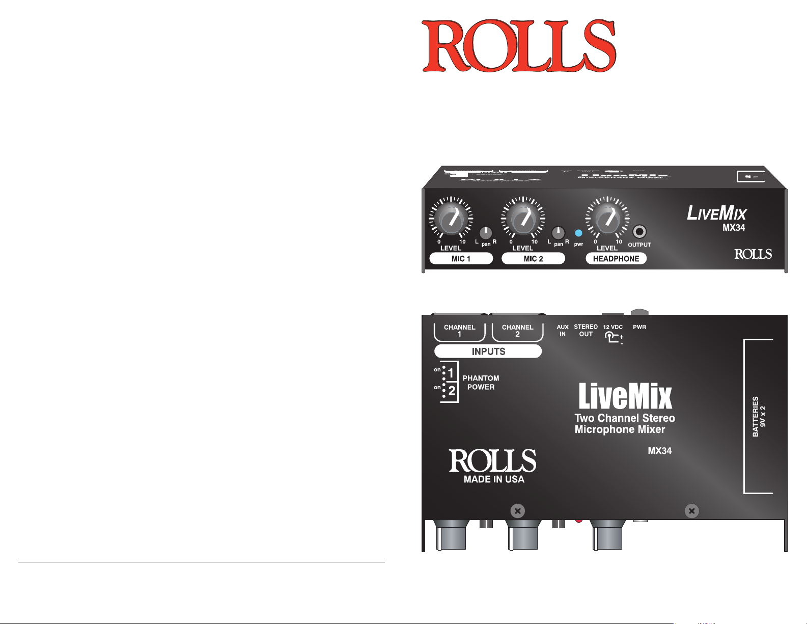
FRONT PANEL
L
IVEMIX
0 10 L R L R
LEVEL
MIC 1 MIC 2 HEADPHONE
0 10
pan
LEVEL
pan pwr
0 10
LEVEL
OUTPUT
MX34
MIC1 and MIC2
LEVEL: Adjusts the amount of signal of the indicated Microphone channel.
PAN: Adjusts the relative level of signal from the channel to the Right/Left Output.
pwr: When lit, indicates that the MX34 is on. A dim light indicates low battery
voltage.
HEADPHONE
LEVEL: Adjusts the amount of signal from the Headphone Output.
OUTPUT: 1/8î (3.5mm) jack containing the Headphone Output signal.
REAR PANEL
12 VDC
PWR
+
-
STEREO
OUT
AUX
IN
CHANNEL
2
INPUTS
CHANNEL
1
INPUTS: 1 - 2: XLR balanced inputs for connection to any standard dynamic or condenser microphone. The input circuitry has a very wide input range and can accomodate
almost any (mic to line) level signal.
AUX IN: Tip-Ring-Sleeve stereo 1/8î (3.5mm) jack for connecting to another line-level
stereo signal source.
STEREO OUT: Tip-Ring-Sleeve stereo 1/8î (3.5mm) jack for connection to a camera or
other stereo input (Line-level only).
12 VDC jack: For connection to the Rolls PS27 12VDC power supply.
POWER: Button applies power to the MX34.
BATTERY INSTALLATION: To replace the 9 V
alkaline batteries, first carefully press in and up on
the door to release the battery compartment. It
then slides out and you can replace the battery.
BATTERY
LIFT TO WITHDRAW
BATTERY
LIFT TO WITHDRAW
Remember to replace both batteries at the same
time.
PHANTOM POWER: The Phantom Power jumpers
are set to the off position from the factory. To engage
the phantom power, first make sure the MX34 is
powered off, use a pair of needle-nose pliers or
tweezers and carefully pull out the jumper corre-
2
CHANNEL
1
CHANNEL
INPUTS
on
POWER
PHANTOM
on
MADE IN USA
sponding to the channel you wish to power. Replace
the jumper - connecting the two pins labeled on.
25
Page 4

CONNECTION
T
OPERATION
Connect microphones to the MX34 via balanced XLR cables.
Stereo auxiliary sources such as the output from another mixer, AM/FM tuners,
CD Players, and MP3 players may be connected to the AUX IN via a stereo 1/8î
(3.5mm) Tip-Ring-Sleeve plug.
Connect the STEREO OUT to the Input of your recording device also using a
stereo 1/8î (3.5mm) Tip-Ring-Sleeve plug.
If you wish to use AC power for the MX34, connect the Rolls PS27 12VDC power
supply.
Once your MX34 is properly connected, apply power by pressing in the POWER
button on the rear panel. The blue pwr LED on the front panel should light.
If you are using condenser type microphones, apply the phantom power by
moving the jumper(s) to the proper setting (see page 2). Test the microphone
levels by speaking into the microphones at a normal operating volume, and adjust
the Mic Level controls until you achieve desired levels. Adjust each Pan control to
place the signal in the stereo field.
Adjust the Headphone Level control for a comfortable listening volume.
For best results, we recommend recording a couple of test runs to ensure you
have proper levels set.
When the signal becomes weak and distorted, and the pwr LED dims, the
batteries will need replacing. See page 2; Battery Installation for details.
Connect STEREO headphones or
earphones to the 1/8î (3.5mm)
HEADPHONE OUTPUT located
on the MX34 front panel.
NOTE: ON CONNECTING A WIRELESS MIC TO THE AUX INPUT
DO NOT CONNECT A MONO PLUG TO
THE AUX IN OR STEREO OUTPUT.
DOING SO WILL RESULT IN SIGNAL
IP RING SLEEVE
STEREO PLUG
LOSS OR DAMAGE TO THE MX34.
If you need to connect a MONO signal (like the
output of a wireless microphone) to the AUX IN
of the MX34, you will need to make or purchase
a MONO TO STEREO cable.Shown here is a
diagram of this cableís wiring.
3 4
Tip and Ring are wired together,
then connected to the Tip of the
Mono Plug.
MONO PLUG
 Loading...