

LIMITED WARRANTY
This product is warranted to the original consumer purchaser to be
free from defects in materials and workmanship under normal installation,
use and service for a period of one (1) year from the date of purchase as
shown on the purchaser’s receipt.
The obligation of Rolls Corporation under this warranty shall be
limited to repair or replacement (at our option), during the warranty period
of any part which proves defective in material or workmanship under
normal installation, use and service, provided the product is returned to
Rolls Corporation, TRANSPORTATION CHARGES PREPAID. Products
returned to us or to an authorized Service Center must be accompanied by
a copy of the purchase receipt. In the absence of such purchase receipt, the
warranty period shall be one (1) year from the date of manufacture.
This warranty shall be invalid if the product is damaged as a result
of defacement, misuse, abuse, neglect, accident, destruction or alteration
of the serial number, improper electrical voltages or currents, repair,
alteration or maintenance by any person or party other than our own
service facility or an authorized Service Center, or any use violative of
instructions furnished by us.
This one-year warranty is in lieu of all expressed warranties,
obligations or liabilities. ANY IMPLIED WARRANTIES, OBLIGATIONS, OR LIABILITIES, INCLUDING BUT NOT LIMITED TO THE
IMPLIED WARRANTIES OF MERCHANTABILITY AND FITNESS
FOR A PAR TICULAR PURPOSE, SHALL BE LIMITED IN DURATION
TO THE ONE YEAR DURATION OF THIS WRITTEN LIMITED
WARRANTY. Some states do not allow limitations on how long an
implied warranty lasts, so the above limitation may not apply to you.
MP1288
MIDIWIZARD
MIDI CONTROLLER
IN NO EVENT SHALL WE BE LIABLE FOR ANY SPECIAL,
INCIDENTAL OR CONSEQUENTIAL DAMAGES FOR BREACH OF
THIS OR ANY OTHER WARRANTY, EXPRESSED OR IMPLIED,
WHATSOEVER. Some states do not allow the exclusion or limitation of
special, incidental or consequential damages so the above limitation or
exclusion may not apply to you. This warranty gives you specific legal
rights, and you may also have other rights which vary from state to state.
RFX
Salt Lake City, UT
5/98
OWNERS MANUAL
INTRODUCTION
2
4
1
5
3
MIDI SIGNALMIDI SIGNAL
PHANTOM PWR
+9 TO +15V
GROUND
MIDI IN
MIDI OUT
POWER
CONTROLLER #
MAP #
MPC#
CHANNEL #
LEARN
SEND
RUN
MP1288
MADE IN USA
PROGRAM
CHANNEL
MAP #
MPC #
CONTROLLER # STORE
0
ID IW IZ A R D
1 2 3 4 5 6 7 8
CONTINUOUS CONTROLLERS
1234
98765
CONTROLLER #
MPC #
MAP #
CHANNEL
MODE
0 - 127
1 - 128
PROGRAM
PWR
0 10
0 10 0 10
FX
RETURN
MASTER VOLUME
LEFT
RIGHT
+17
+8
0
-4
-13
SM 1
PWR
0 10
0 10 0 10
FX
RETURN
MASTER VOLUME
LEFT
RIGHT
+17
+8
0
-4
-13
SM 2
PWR
0 10 0 10
MASTER VOLUME
LEFT
RIGHT
+17
+8
0
-4
-13
DSP1
To SM1 MIDI Input
From SM1 MIDI Through
To SM2 MIDI Input
From SM2 MIDI Through
To DSP1 MIDI Input
12
06
18
Thank you for purchasing the MP1288 MIDIWIZARD. The MP1288 was designed
to give you control of a whole universe of MIDI-compatible processors, keyboards,
sequencers, MIDI-linked PC terminals or anything else than can receive MIDI on
any of the 16 standard MIDI channels.
The MIDI WIZARDS's compact, durable chassis and low profile make it easily
integrated into the sometimes crowded studio or stage environment. And, if you
choose not to use it as a foot controller, the Wizard is designed to fit into an extra
rack space in any 19 inch audio rack. As with ev ery RFX MIDI unit, it is Phantom
powerab le, which eliminates the need f or a separate pow er cord. The 1288 has
RFX MIDI PHANTOM POWER
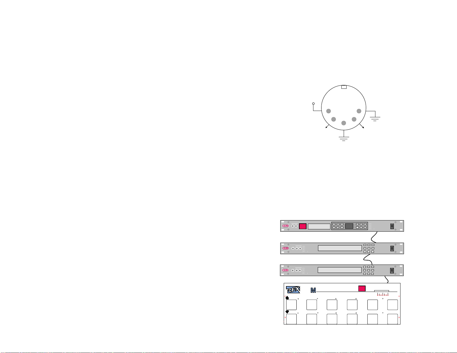
Inspired by an article in the December 1989 issue of Electronic Musician (by
Craig Anderton), we decided to emulate their MIDI phantom pow er model for RFX
equipment. MIDI receivers supply 12 VDC on pins 1 and 3, and transmitters
receive power on those same pins. Many MIDI devices can be modified to supply
power down the cable, but of course RFX makes no warranty to any one as to the
applicability of this modification or any damage that might be done as a result
thereof. We supply this note for those adventurous people who may w ant to give it
a try.
Connect pin 1 to circuit ground, and pin 3 to +9 - +15 VDC of the receiving unit.
the power and memory capabilities to become the nerve center of an entire MIDI
recording studio as well as live situation. The Wizard can send up to 8 program
changes to 8 different MIDI-linked units for each program number assigned to the
pedal. Also up to 8 continuous controllers can be used to very parameters directly
on the receiving unit in real-time.
TABLE OF CONTENTS
INTRODUCTION 1
TABLE OF CONTENTS 1
POWER-UP 1
DESCRIPTION 2
OPERATION 2
Definition of Terms 2
MIDI Channel 3
Standard SEND Mode 3
LEARN (Programming) Mode 3
Changing Display Count and MIDI Channel 3
MAPS 4
Using Continuous Controllers 5
SPECIFICATIONS
Data Sent: MIDI Program Change and MIDI Contin uous Control
Size: 17" X 6" X 1.5" (381 x 153 x 38 mm)
Weight: 4 lbs. (1.4 kg)
P ow er: 7 - 15 VAC/VDC 120 mA
Phantom Power: 7 - 25 VDC 120 mA, pin 1 neg, pin 3 pos.
Display: 2 digit red, .56" high efficiency
Output: Standard MIDI Program Change, Continuous Control
Output Jacks: 2 5-pin DIN jacks (MIDI OUT, MIDI SHARE)
Chassis: Black painted steel
Clearing the Memory 5
MIDI T est Mode 5
RFX MIDI Phantom Power 6
SPECIFICATIONS 6
MAPPING Example Diagram 6
WARRANTY Back Cover
POWER-UP
P ow er-up of the MP1288 is accomplished by using the supplied AC pow er
adapter, or by connecting the MIDI OUT jack to any MIDI unit with Phantom
power capabilities using an y standard MIDI cable.
The MIDI IN links other MIDI devices into the MIDI line and merges them to avoid
data collisions. (For example, 2 MP1288s operating on different MIDI channels
could be used together and use the same MIDI cord.)
1 6
(Mapping Example from page 4.)
USING CONTINUOUS CONTROLLERS
The CONTINUOUS CONTROLLER jacks on the top of the MP1288 are input
jacks f or separate controlling devices. These controllers can be 0 - 5 volt voltage
control pedals, or a unit that uses a variab le resistance to ground, such as the
RFX 402p volume pedal.
If you have a pedal with 0 - 5 v oltage control range, just plug it in and start programming. Howev er, if a variable resistance controller is used, the actual control
range may vary depending on the potentiometer in the pedal. Check the manual of
the receiving unit(s) for the controller numbers of the parameters you wish to
control. The 1288 can accommodate controller numbers 0 - 122.
Connect the pedal to the jack you wish to use, (Several different pedals can be
used depending of the functions of the unit(s) being controlled).
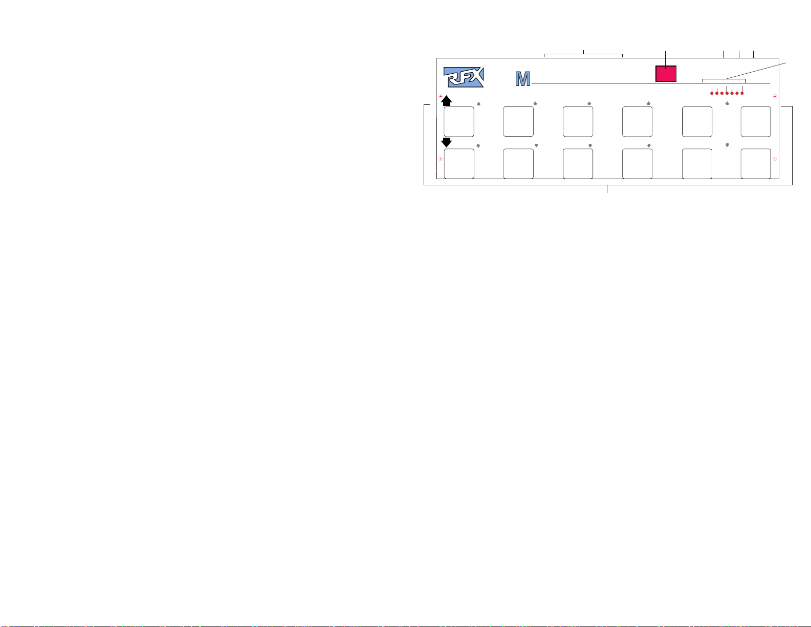
DESCRIPTION
PROGRAM
PROGRAM
1 2 3 4 5 6 7 8
ID IW IZ A R D
0
CHANNEL
CHANNEL
5
A B CDE
MIDI IN
POWER
CONTINUOUS CONTROLLERS
CONTROLLER #
1234
MAP #
MAP #
MPC #
MPC #
CONTROLLER # STORE
CONTROLLER #
MIDI OUT
CHANNEL #
MAP #
MPC#
MP1288
RUN
MADE IN USA
LEARN
SEND
MODE
9876
0 - 127
1 - 128
F
While still in LEARN mode, click down to A PROGRAM button until [C1] to [C8]
G
shows in the number display. Now select the channel of the unit to receiv e the
controller signal and press STORE.
A: Continuous Controller input jacks. 1/4" jacks (tip-sleeve only) for receiving 0-5
volt continuous controller voltages, or standard resistive volume pedal outputs.
Example - Your wah/v olume pedal comes equipped with an output jack that makes
it double as a voltage controller. Y our guitar signal processor lets you remotely
adjust the Chorus speed, master volume or hi-mid-lo settings. Since the guitar
signal processor is set for MIDI channel 2, plug the controller into CONTINUOUS
CONTROLLER jack number 1 and assign jack number 1 to MIDI channel 2. This
is done by selecting the Program button while the CONTINUOUS CONTR OLLER
# LED is lit and then selecting MIDI channel 2 - since the receiving unit is set for
MIDI channel 2.
B: 3-digit high-efficiency number display for:
• Displaying the program number being accessed while in normal SEND
mode.
• Displaying MAP numbers, MIDI channel numbers, and CONTINUOUS
CONTROLLER numbers being assigned while in LEARN mode.
C: MIDI IN jack. 5-pin jack f or connection to the MIDI device to be controlled.
E: POWER jack. For connection to the 12 VAC or DC supply.
F: Function LED indicators . Indicate the following:
• The SEND LED indicates that a MIDI signal being sent to the unit(s)
CLEARING THE MEMORY - FACTORY PRESET
The MP1288 can be reset as it came from the factory by simply holding down
both CHANNEL buttons while in the LEARN mode.
• The display will show [FP] (meaning factory preset) for about 60
seconds then clear. This clears all previously progr ammed information.
being controlled.
• The RUN LED indicates the unit is in "send" mode.
• The LEARN LED indicates the unit is in "learn" mode.
• As you assign each MAP #, CHANNEL #, MIDI PROGRAM CHANGE
(MPC) #, or CONTROLLER #, the corresponding LED will stay lit.
G: Function Footpads. For performing the following functions:
MIDI TEST MODE
The 1288 comes with a bonus testing mode for testing other MIDI transmitters.
To access the TEST Mode, hold the tw o PROGRAM buttons down on power-up .
Connect the unit to be tested to the MIDI IN jack of the 1288, and send a signal
• Incrementing, decrementing, and programming Program #s, MIDI
Channel #s, MIDI Map #s, MPC #s, Continuous Controller #s, and
MODEs.
• STOREs and directly accesses program #s.
from the test unit. The MIDI WIZARD will display the channel and the program
change number (MPC#) coming in from the unit being tested.
If a controller is being tested, the display will show the channel number, then the
controller number while lighting the CONTROLLER # LED.
In this mode, all the buttons on the MP1288 are inactive because the 1288 is only
an input testing device. This features makes the MP1288 a very useful tool when
troubleshooting any MIDI transmitting de vice.
TO EXIT MIDI TEST MODE YOU MUST UNPLUG THE POWER FROM THE
MP1288.
OPERATION
DEFINITION OF TERMS
In order for you to clearly understand progr amming and operating your MP1288,
you must u
nderstand the following terms:
Program - Refers to the MP1288 Program Number , the number displayed on the
1288.
Preset (or Program Change Number), refers to the MIDI number sent by the
MP1288.
5 2
MAP or PATC H refers to Program Changes (up to 8 total) sent b y one Program of

MIDI Channel - Refers to the specific channel the MIDI data is being transmitted
and received upon. Much like radio operation, both the radio station and your radio
must be tuned to the same channel in order to communicate. There are 16 MIDI
channels in which to send and receive upon.
Standard SEND mode
Upon power-up , the MP1288 is in SEND or standard operating mode.
The MP1288 may be switched to accommodate units that count from 0 to 127, or
from 1 to 128. (see LEARN mode).
Program number changes are sent to the unit(s) being controlled by simply sing
the leftmost PROGRAM UP or PROGRAM DOWN buttons. This selects the 10's
digit.
The buttons labeled in white and marked 0 through 9 select the 1's digit. MIDI data
is sent out when a 1's digit is pressed, and the SEND LED will flash.
Example: If y ou want to access program number 47 on a MIDI controlled unit upon power-up , the display shows [0-]. Push the PROGRAM UP button 4 times,
the display n ow reads [4-]. Now, press the 7 button and the display will read [47],
and program change n umber 47 will be sent to the receiving unit (it should also
read 47). You may also select multiple presets (up to 8) on multiple units using the
MIDI MAPS (see MAPS) section.
LEARN (Programming) Mode
In order to change MIDI Channels, program MIDI MAPs , change the Display
Count, and program the Continuous Controller function, you
LEARN Mode. To access the LEARN mode, simply hold down both PROGRAM
buttons for about 5 - 7 seconds.
• The LEARN LED will light and the display will be [00]].
To exit the LEARN mode, and return to SEND or standard mode, hold down both
PROGRAM buttons again for 5 - 7 seconds.
Changing display count (0-127 or 1-128)
To select the display count mode, press the MODE button.
• Access LEARN Mode.
• The display will flash [01 to 128] or [0 to 127], the last one you see is the
one selected. To select the other one, press ?.
Changing the MIDI Channel
To change the MP1288's send MIDI Channel, press a CHANNEL button while [00]
is displayed at the start of LEARN Mode, then press STORE.
• Access LEARN Mode
• The display now counts through all the program numbers, changing
them to the new channel.
Remember, the MP1288's channel numbers can be programmed on an individual
or group basis (see MAPS).
• When the display reads [00] for the program number , the MIDI channel
number will be for ALL program change numbers. CAUTION: This will erase all
MAP numbers so the main MIDI channel number should be selected first.
** Remember, all PROGRAMMING functions are marked on the chassis in BLUE,
and all SEND functions are in WHITE. **
must
first be in
3 4
MAPS
An example is the best way to explain this procedure, a graphic representation is
shown on P age 6.
For our example, we want Preset #1 (that’s the number that will be displayed on
the MP1288) to change the SM1 (Sound Module) to program number 12, the SM2
to program number 6, and the DSP1 (Digital Signal Processor) to program
number 18. Then, we’ll hav e the MP1288 Preset #2 change the SM1 to program
number 7 and the SM2 to program number 14, leaving the DSP1 alone .
Since the MP1288 always sends out a program change number that’s the same
as the preset number, set the MP1288 main MIDI channel to a number that is
NOT being used by any of the devices that's being controlled. Let's use channel
13. This procedure is explained on page 3.
1. Press and hold the Program up and down buttons to enter LEARN mode.
2. Press the Program Up button to tell the MP1288 that we’re programming
Preset number one. (I realize this is confusing because it says “Program Up and
Down” on the MP1288 and I call them Presets - but there must be a distinction
made between the numbers displayed on the MP1288, and the program numbers
displayed on your MIDI devices being controlled.) 01 should be displayed.
3. Press the Map # Up button - 01 should be displayed. This is the first Map.
4. Press the MPC (MIDI Program Change) # Up button. It should display a 00.
Press the MPC # Up button twelve times to change the display to 12.
5. Press the MIDI Channel Up button. Change it to 01.
6. Press the Map # Up button again - change it to 02. This is the second Map.
7. Press the MPC # Up button - change it to 06 by pressing it 6 more times.
8. Press the MIDI Channel Up button - change it to 02.
9. Press the Map # Up button again - change it to 03. This is the third Map.
10. Press the MPC# Up button again and change it to 18.
11. Press the MIDI Channel Up button again and change it to 03.
12. Press STORE.
13. Press the Program Up button again - we’re going to prog ram Preset #2.
14. Press the Map # Up button and change it to 01
15. Press the MPC# Up button and change it to 07.
16. Press the Channel Up button and change it to 01 - the proper MIDI channel for
the SM1.
17. Press the Map # Up button and change it to 02.
18. Press the MPC # Up button and change it to 14.
19. Press the Channel button and change it to 02.
20. Press STORE.
21. Now press and hold the Program Up and Do wn buttons until the MP1288
returns to Run Mode.
In order for all of this to work, your first device (the SM1) must be on MIDI Channel 01, the second device (the SM2) must be on channel 02, and the third device
(the DSP1) must be on MIDI channel 03. Refer to their respective owner’s manuals to learn how to do that.
Remember that the MP1288 must be on an overall MIDI channel of something
other than 01, 02 or 03. Go to bank number 0, so the display shows a 0-, and
press the #1 button. Hopefully, if everything was done right, your three devices
went to the correct program numbers. Press the #2 button and the SM1 should
change to program number 7 and the SM2 to prog ram number 14, the DSP1
should remain unchanged.
 Loading...