

Page 1
LIMITED WARRANTY
This product is warranted to the original consumer purchaser to be free from
defects in materials and workmanship under normal installation, use and service for a
period of one (1) year from the date of purchase as shown on the purchaser’s receipt.
The obligation of Rolls Corporation under this warranty shall be limited to repair
or replacement (at our option), during the warranty period of any part which proves
defective in material or workmanship under normal installation, use and service, provided
the product is returned to Rolls Corporation, TRANSPORTA TION CHARGES PREPAID. Products returned to us or to an authorized Service Center must be accompanied by
a copy of the purchase receipt. In the absence of such purchase receipt, the warranty
period shall be one (1) year from the date of manufacture.
This warranty shall be invalid if the product is damaged as a result of defacement, misuse, abuse, neglect, accident, destruction or alteration of the serial number,
improper electrical voltages or currents, repair, alteration or maintenance by any person or
party other than our own service facility or an authorized Service Center, or any use
violative of instructions furnished by us.
This one-year warranty is in lieu of all expressed warranties, obligations or
liabilities. ANY IMPLIED WARRANTIES, OBLIGATIONS, OR LIABILITIES,
INCLUDING BUT NOT LIMITED TO THE IMPLIED WARRANTIES OF MERCHANT ABILITY AND FITNESS FOR A PARTICULAR PURPOSE, SHALL BE
LIMITED IN DURATION TO THE ONE YEAR DURATION OF THIS WRITTEN
LIMITED WARRANTY. Some states do not allow limitations on how long an implied
HM58
Headphone Monitor Remote
OUTPUT
AUX 1
MAIN
IN
AUX 2 AUX 3 AUX 4
FX RETURN
BASS MID TREB
HEADPHONE
MONITOR
REMOTE
AGC
COMP
MASTER
OUT
PWR
HM58
warranty lasts, so the above limitation may not apply to you.
IN NO EVENT SHALL WE BE LIABLE FOR ANY SPECIAL, INCIDENTAL
OR CONSEQUENTIAL DAMAGES FOR BREACH OF THIS OR ANY OTHER
WARRANTY, EXPRESSED OR IMPLIED, WHATSOEVER. Some states do not allow
the exclusion or limitation of special, incidental or consequential damages so the above
limitation or exclusion may not apply to you. This warranty gives you specific legal
rights, and you may also have other rights which vary from state to state.
ROLLS CORPORATION
SAL T LAKE CITY, UT AH
3/00
NOTE: THIS UNIT REQUIRES A ROLLS HM60 OR
HM57 FOR OPERATION.
OWNERS MANUAL
Page 2
INTRODUCTION
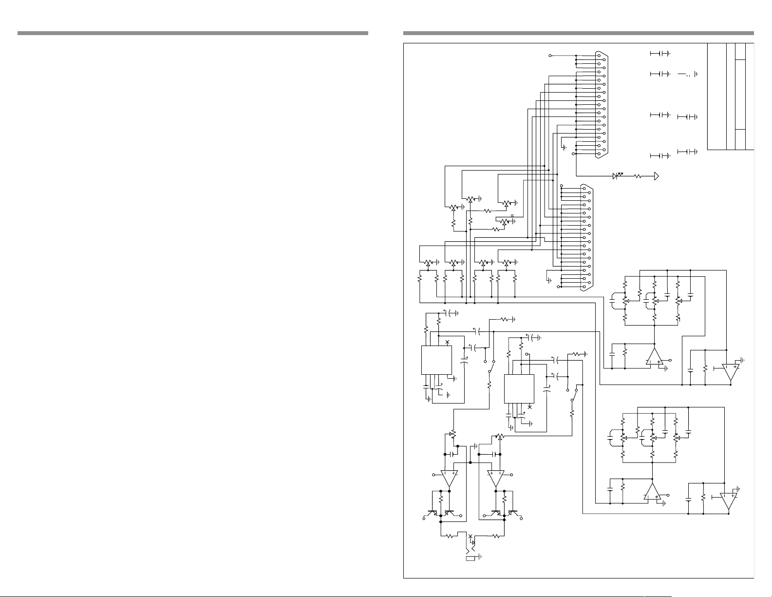
SCHEMATIC
Thank you for y our purchase of the Rolls HM58 Headphone Monitor Remote. This
unit, along with either the HM60 Headphone Monitor System or HM57 Head-
VDD
phone Monitor Interface, allows y ou to mix f our mono signals with tw o stereo
signals for your own personal monitoring needs. It includes equalization and AGC
compression.
Please read the following manual carefully to get the best results from y our HM58.
TABLE OF CONTENTS
Introduction 1
Table of Contents 1
Inspection 1
Specifications 1
Description
Back Panel 2
Front P anel 2
Connection 3
Operation 4
P 1 B
P 1 0 0 K X 2
R M A I N
P 1 A
P 1 0 0 K X 2
1 3
P 2 A
L M A I N
4 6
2
5
R 7 2 2 K
R 8 2 2 K
P 1 0 0 K X 2
1 3
4
R 6
2 2 K
2
R R E T L R E T
R 5
4 6
2 2 K
5
P 2 B
P 1 0 0 K X 2
Block Diagram 5
Schematic 6
Warranty Rear Cover
INSPECTION
1. Unpac k and inspect the HM58 bo x and pac kage .
If obvious physical damage is noticed, contact the carrier immediately to make a
damage claim. We suggest saving the shipping carton and packing materials for
safely transporting the unit in the future.
2. Please complete the Warranty Registration Card and return it to the factory.
SPECIFICATIONS
Output Impedance: 10 Ω
Sensitivity: V ariable , -10 to +4 dB f or rated output
Po wer Output: >500 mW at 32 Ω
(>150 mW at 600 ohms) 20 Hz to 20 KHz.
Connectors: Outputs: 1/4" TRS stereo headphone jac k,
DB25 (25 pin) jack
Distortion: 0.008% THD full po wer @ 1 KHz;
0.05% THD 20Hz to 20 KHz
Dynamic Range: Greater than 96 dB
Freq. Response: 20 Hz to 20 KHz, +0, -1 dB 400 mW output
Power Requirement
: Receives power from HM60 or HM57
Dimensions: 7.5” W x 3.35” H x 1.625”D
Weight: 1.5 lbs.
1 6
P 6
R 9
2 2 K
R 3 0 3 3 K
5
N E 5 7 0
1 2 0 P F
1 5
VCC
P 1 0 0 K
8
R 1 0
2 2 K
R 1 1
C 2
R 2 9 3 3 K
6
0
7
R3
V+
INV
OUT
U 4 A
THD8DG3RIN2RC1GND
4
2
6
8
VCC
4 5 6 0
7
3 0
R 1
Q 1
M P S A 0 6
R 4
P 7
P 1 0 0 K
P 8
P 1 0 0 K
P 9
R 1 3 2 2 K
1 0 U
S W 1 A
C 1 5
Q 2
VCC
P H O N E 1 / 4
1 0
R 1 4 2 2 K
R 1 5 2 2 K
R 3 3
1 0 0 K
123
R 3 2 3 3 K
D P D T
N E 5 7 0
C 1 8
1 2 0 P F
P 1 0 B
P 1 0 0 K X 2
46
5
2 7 P F
3
2
U 1 A
4 5 6 0
1
R 2
M P S A 0 6
R 3
1 0
P 1 0 0 K
1 1
R 1 6 2 2 K
1 7
R 3 1 3 3 K
VCC
12
10
11
R3
INV
OUT
THD9DG14RIN15RC16GND
2 0
4
VDD
3 0
Q 4
2 N 2 9 0 7
VDD
VCC
1 8
C 6
1 0 U
C 7
1 0 U
13
C 5
V+
1 0 U
0
C 1 0
1 U
1 9
9
2 2 K
R 1 2 2 2 K
1 0 U
1 2
C 3
C 1
1 0 U
C 4
1 0 U
1 4
P 1 0 A
P 1 0 0 K X 2
1 3
3
C 1 6
2 7 P F
5
U 1 B
Q 3
2 N 2 9 0 7
VDD
1 0
J 1
H D P H N / L O U T
VDD
1
14
2
15
3
16
4
17
5
18
6
19
7
20
8
21
9
22
10
23
11
24
12
25
13
VCC
1
14
2
15
3
16
4
17
5
18
6
19
7
20
8
21
9
22
10
23
11
24
12
25
13
R 3 4
1 0 0 K
1 6
456
S W 1 B
D P D T
R 1 7
2 2 K
J 2
D 1
L D S R
R 4 3
B A S S
R 2 3
1 0 K
13
J 3
D B 2 5 f e m a l e
P 3 A
R 2 5
C 3 8
. 0 4 7
R 2 4
1 0 K
C 1 3
2 7 P F
R 2 0 1 8 K
R 2 6
1 0 K
46
R 2 8 1 0 K
C 3 7
C 1 1
5
. 0 4 7
P 3 B
R 2 7
1 0 K
R 1 9
1 8 K
2 7 P F
2 7
VCC
C 2 5
. 1
2 5
C 2 3
VCC
C 2 2
VCC
C 2 0
3 . 3 K
M I D D L E
R 3 6
4 . 7 K
13
P 4 A
1 0 K
C 3 1
2
C 3 6
. 0 0 5
R 3 5
4 . 7 K
1
U 3 A
4 5 6 0
3 5
2
3
R 3 8
4 . 7 K
46
C 3 2
. 0 0 5
P 4 B
C 3 5
R 3 7
4 . 7 K
1
U 2 A
4 5 6 0
3 6
2
3
2 6
. 1
C 2 1
. 1
2 4
2 3
VDD
. 1
C 1 9
. 1
2 1
VDD
2 2
. 1
T R E B L E
R 3 9
2 . 2 K
13
P 5 A
. 0 2 2
C 3 3
2
5
. 0 0 5
2
R 4 0
2 . 2 K
4
VDD
C 1 4
2 7 P F
R 2 2 1 0 K
R 4 1
2 . 2 K
46
. 0 2 2
C 3 4
. 0 0 5
5
P 5 B
R 4 2
2 . 2 K
4
VDD
C 1 2
2 7 P F
R 2 1 1 0 K
5143 South Main Street
ROLLS CORPORATION
Salt Lake City, UT 84107
R O L L S H E A D P H O N E M O N I T O R S Y S T E M R E M O T E 2
Title
6
8
VCC
U 3 B
4 5 6 0
7
6
5
8
VCC
U 2 B
4 5 6 0
7
Rev:
D O C U M E N T N U M B E R
Size:
5
3 3
3 4
15-Oct-1999
A
1 of
H M 5 8 . S C H
Rb
Date:
Page 3
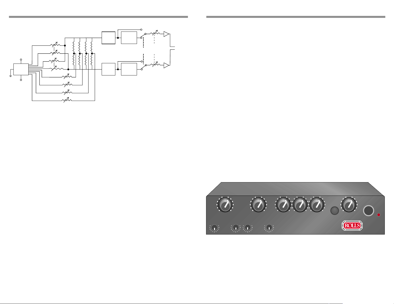
BLOCK DIAGRAM
FX
RETURN
+V
DB25
MULTI-PIN
CONNECTOR
-V
MAIN LEVEL
MONO AUX LEVELS
EQUALIZER
EQUALIZER
COMPRESSOR
COMRPESSOR
COMPRESSOR
IN/OUT
MASTER
OUTPUT
LEVEL
Headphone
Output
DESCRIPTION
BA CK PANEL
EXPANSION PORTS: Male and Female 25 pin parallel port jacks.
FRONT PANEL
NOTE: All HM58 controls adjust the levels of input signals connected to either the
HM60 or HM57. With the exception of the HM60 Effects Send controls, all other
HM60 knobs will have no eff ect on the signals sent to the HM58.
MAIN IN:Controls the level of the main Stereo Input
FX RETURN: Adjusts the le v el of signal returning from a signal processor which is
connected to an HM60.
BASS: Boosts or cuts the low frequency portion of the signals sent to the Headphone Output. When in the 12 O’clock position, the knob has no effect.
MID: Boosts or cuts the middle frequency portion of the signals sent to the
Headphone Output. When in the 12 O’clock position, the knob has no effect.
TREBLE: Boosts or cuts the high frequency portion of the signals sent to the
Headphone Output. When in the 12 O’clock position, the knob has no effect.
AGC COMP: This switch engages the A utomatic Gain Control compressor .
MASTER OUT: Controls the le v el of all signals sent to the Headphone Output.
OUTPUT: 1/4” TRS stereo jack containing all mix ed and processed signals .
PWR: LED indicating that the HM58 is properly connected to the HM60 or HM57
and is receiving power .
AUX1 - AUX4: Adjusts the le v el of input signals to from the indicated input.
OUTPUT
AUX 1
MAIN
IN
AUX 2 AUX 3 AUX 4
FX RETURN
BASS MID TREB
HEADPHONE
MONITOR
REMOTE
AGC
COMP
MASTER
OUT
PWR
HM58
5 2
Page 4
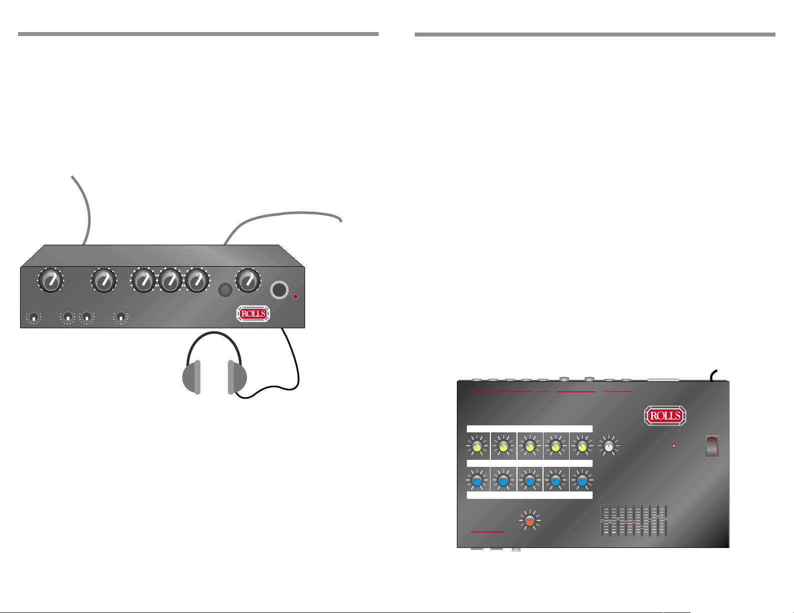
CONNECTION
OPERATION
CONNECTING THE HM58
Shown below is a connection diagram for the HM58. The male Expansion jack,
shown below on the left side, is the INPUT, the female Expansion jack, shown
here to the right, is the OUTPUT or through jack. So connect the DB25 e xpansion
cable from the female OUTPUT Expansion jack of either the HM60 or HM57 to
the male INPUT Expansion jack on the HM58. The female OUTPUT Expansion
jack on the HM58 may then be connected to another HM58 or HM59.
From HM60
or HM57
To other
HM58 or HM59
REMOTE
UNITS
LVL 1
MAIN
IN
LVL 2 LVL 3 LVL 4
FX RETURN
BASS MID TREB
HEADPHONE
MONITOR
REMOTE
AGC
COMP
MASTER
OUT
OUTPUT
PWR
HM58
OPERA TING THE HM58
After proper connections are made, begin sending signals to the HM60 or HM57,
whichever is connected to the signal sources and y our HM58.
• Set the HM58 Master Level control at approximately 12 O’clock. Carefully bring
up the AUX 1 - 4 le vels until a desired mix is achieved.
• Adjust the Equalizer as needed.
• The A GC compressor keeps transient signals like pops or feedback under
control, so they won’t damage your hearing. It also slightly brings up low-level
signals.
NOTE: Much of the signal content may not be compressed, you ma y not
notice any effect. Only very high level or lo w le vel signals are effected.
• If using external effects processors, make sure the y are properly connected to
the HM60, and the levels are set properly. Refer to the HM60 owners man ual, as
well as the operating manual of the effects processor.
If you hav e an eff ects processor connected to the HM60 control unit, the HM58
Effects Return adjusts the level of the eff ected signals to y our headphone mix.
Note that the Effects Sends 1 - 4 and MAIN on the HM60 determine the mix of
signals sent to the effects processor . The HM58 FX Return control will only adjust
the level of that mix. In other words, the signals present at the Right and Left
Effects Return jacks on the HM60 will be the signals adjusted by the FX Return
control on the HM58.
1
1
MIX OUTPUT
PHONE/
LEFT
2
MONO INPUTS
RIGHT
4
3
EFFECTS SENDS
MIX LEVELS
234
AGC
COMP
SEND
FX
MASTER
LEVEL
RIGHT
STEREO
INPUTS
MAIN
LEFT
+12
-12
EFFECTS
0
64 125
R
L
EFFECTS
RETURN
RETURN
HEADPHONE
MONITOR
SYSTEM
EQUALIZER
500
250
1K 2K 4K 8K 16K
EXPANSION
PWR
120 VAC
50/60Hz
3 4
 Loading...