

Page 1
LIMITED WARRANTY
This product is warranted to the original consumer purchaser to be free
from defects in materials and workmanship under normal installation, use and
service for a period of one (1) year from the date of purchase as shown on the
purchaser’s receipt.
The obligation of Rolls Corporation under this warranty shall be limited
to repair or replacement (at our option), during the warranty period of any part
which proves defective in material or workmanship under normal installation,
use and service, provided the product is returned to Rolls Corporation, TRANS
PORTATION CHARGES PREPAID. Products returned to us or to an authorized
Service Center must be accompanied by a copy of the purchase receipt. In the
absence of such purchase receipt, the warranty period shall be one (1) year from
the date of manufacture.
This warranty shall be invalid if the product is damaged as a result of
defacement, misuse, abuse, neglect, accident, destruction or alteration of the se-
rial number, improper electrical voltages or currents, repair, alteration or mainte
nance by any person or party other than our own service facility or an authorized
Service Center, or any use violative of instructions furnished by us.
This one-year warranty is in lieu of all expressed warranties, obligations
or liabilities. ANY IMPLIED WARRANTIES, OBLIGATIONS, OR LIABILI
TIES, INCLUDING BUT NOT LIMITED TO THE IMPLIED WARRANTIES
OF MERCHANTABILITY AND FITNESS FOR A PARTICULAR PURPOSE,
SHALL BE LIMITED IN DURATION TO THE ONE YEAR DURATION OF
THIS WRITTEN LIMITED WARRANTY. Some states do not allow limitations
on how long an implied warranty lasts, so the above limitation may not apply to
you.
IN NO EVENT SHALL WE BE LIABLE FOR ANY SPECIAL, INCI
DENTAL OR CONSEQUENTIAL DAMAGES FOR BREACH OF THIS OR
ANY OTHER WARRANTY, EXPRESSED OR IMPLIED, WHATSOEVER.
Some states do not allow the exclusion or limitation of special, incidental or con-
sequential damages so the above limitation or exclusion may not apply to you.
This warranty gives you specific legal rights, and you may also have other rights
which vary from state to state.
-
-
-
GCi404
Audio Computer Interface
-
OWNERS MANUAL
Page 2
INTRODUCTION
Thank you for your purchase of the GCi404 Audio Computer Interface. The GCi404
mixes a balanced XLR Microphone signal with a 1/4” Instrument signal and a group
of stereo Line Input signals to connect to any standard computer sound-card.
A ducking feature has been included in the GCi404 which, when engaged and a
signal is present at the microphone, will duck the remaining input signals under the
mic signal.
Uses for the GCi404 include commercial audio production, produce your own “commercial” on your computer, phonograph record to computer recording, etc.
FEATURES:
• Microphone input with 12 volt phantom power
• Instrument input
• RCA Line Input, Stereo 1/8” Line Input, RCA Phono Input with Ground post and
RIAA equalization and Rumble Filter
• Individual Level controls for Mic, Instrument and Line Inputs
• Switchable automatic “Ducking” or talkover feature for Mic Input
• Stereo RCA, 1/8” TRS stereo, or 4-pin header connector Outputs
INSPECTION
1. Unpack and inspect the GCi404 box and package.
Your GCi404 was carefully packed at the factory in a protective carton. Nonetheless, be sure to examine the unit and the carton for any signs of damage
that may have occurred during shipping. If obvious physical damage is noticed,
contact the carrier immediately to make a damage claim. We suggest saving
the shipping carton and packing materials for safely transporting the unit in the
future.
2. Please complete the Warranty Registration Card and return it to the factory.
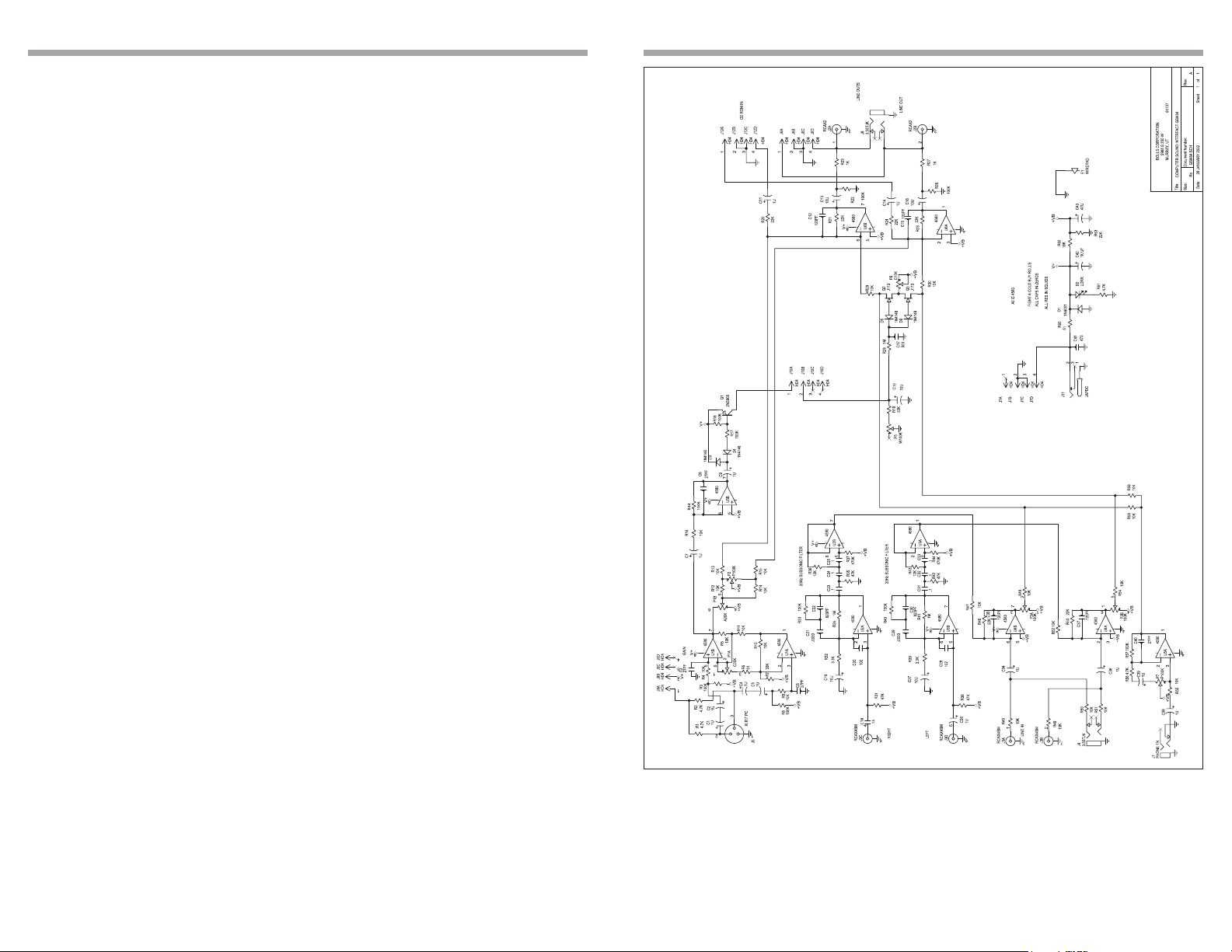
SCHEMATIC
TABLE OF CONTENTS
Introduction 1
Features 1
Inspection 1
Table of Contents 1
Description 2
Front Panel
Rear Panel
Connection 3
Operation 4
Computer Mounting
Signal Level Adjust.
Ducking
Specifications 5
Schematic 6
Warranty Back cover
1
6
Page 3

SPECIFICATIONS
DESCRIPTION
MIC INPUT
Input Impedance: 10K Ohms bal, unbal.
Max Input Level:
+4 dBV XLR bal, +10 dBV unbal.
Max Gain: 60 dB/XLR, 54 dB 1/4”
EIN: -108 dB max.
THD: <.01%
Phantom Power: +12 Volts, 6 mA
INSTRUMENT INPUT
Input Impedance: 50k Ohms
Max Gain: 30dB
LINE INPUTS
Input Connectors: RCA, 1/8” TRS Stereo
Input Sensitivity: 30 dB gain @ 1kHz, 47k Ohms Input Z
Input Impedance: 50k Ohms
PHONO PREAMP
Input Impedance: 50k Ohms
Equalization: RIAA, +/- 2dB
Ref. Gain: +20 dB @ 1 kHz
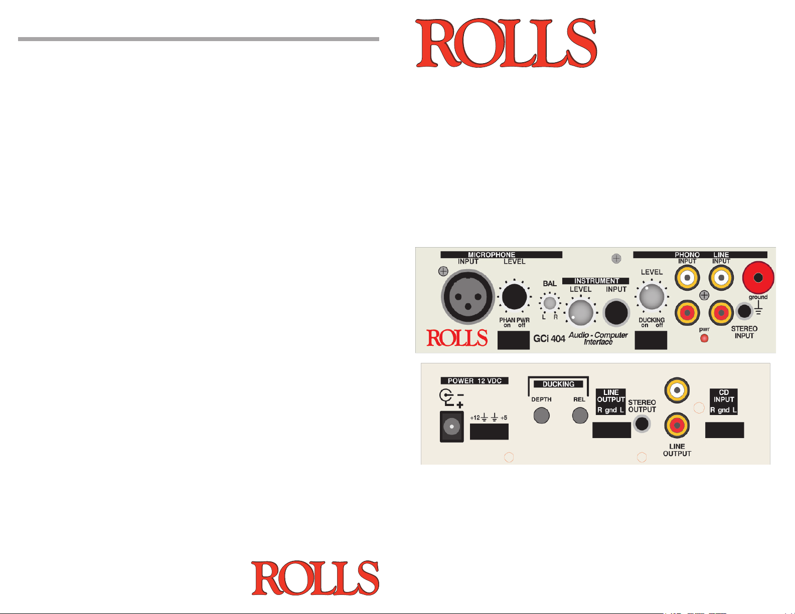
FRONT PANEL
MICROPHONE
INPUT: Balanced XLR
jack for connection to low impedance dynamic or condenser microphone.
LEVEL: Adjusts the amount of signal in the microphone preamp.
PHANTOM PWR: Header connector - connects the 12VDC phantom
power for the XLR Microphone Input.
BAL: Varies the relative amount of microphone signal sent to the Right
and Left Outputs.
INSTRUMENT
LEVEL: Adjusts the amount of signal in the instrument circuitry.
INPUT: 1/4” unbalanced jack for connection to instruments such as
guitars, keyboards, etc.
PHONO/LINE
LEVEL: Adjusts the level of all deviced connected to the Phono or Line
Inputs.
INPUT (Phono): Two RCA jacks for connection specifically to the output of
a phono turntable.
INPUT (Line): Two RCA jacks for connection to line or consumer product
outputs such as a CD or cassette player.
STEREO INPUT: 1/8” (3.5mm) TRS stereo jack for connection to a stereo line
source such as a portable CD player or MP3 player.
GROUND: For connection to the grounding cable of a phono tuner.
DUCKING: Header connector - connects the Ducking function.
PWR: Indicates the GCi404 is properly connected to a power source.
REAR PANEL
LINE OUTPUTS
Output Impedance: 100 Ohms
Max Output Level: +12 dB
Frequency Response: + / - 1.5dB 15 Hz - 30 kHz
THD: .02% @ 1KHz
S/N Ratio: >80 dB unweighted
Output Connectors: RCA, 1/8” TRS - Stereo, 4-pin hdr.
Dimensions: 1.7”H x 5.9” W x 3.7” D
Weight: 1 lb.
Power: 12VDC (Rolls PS27 Incl.)
5
POWER: 12VDC, 150mA. 2.1 x
5.5mm barrel jack and header port
- for connection to the Rolls PS27 AC
adapter, or to the computer’s 3 1/2
inch floppy drive power cable.
DUCKING
DEPTH: Adjusts the amount of LINE signal allowed to pass to the Outputs
when ducking is occuring.
RELEASE: The amount of time taken for the ducked LINE signal to return
to its normal level after the sigal at the Mic Input stops.
CD INPUT Port: 4-pin header for connecting to a CD rom output port. A CD Rom audio
cable is required.
LINE OUTPUTS:
STEREO OUTPUT: (1/8” (3.5mm) jack)
LINE OUTPUT (RCA):
LINE OUTPUT (Header Port):
Each of these outputs contain the Right and Left output signals.
2
Page 4
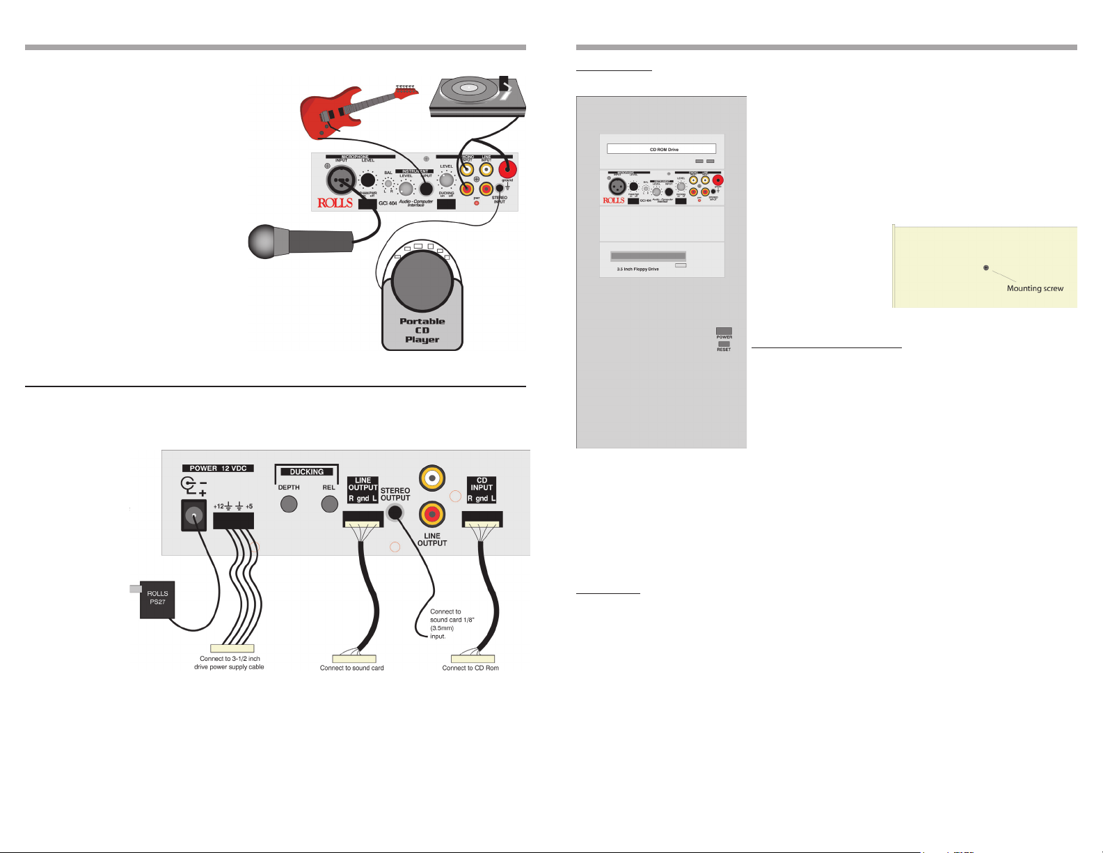
CONNECTION
OPERATION
Shown here is an example of possible input connections to the GCi404.
• If the microphone connected to the
Mic Input is a condenser microphone, move the Phantom Power
jumper to the ON position.
• The guitar signal may also be
connected to a guitar preamp or
processor before being connected
to the GCi404.
• Turntables must use all three connections; the Right, Left, AND the
Ground terminals are required for
proper operation.
• Standard CD players may be connected to the RCA LINE INPUT in
the same manner as the Portable
CD Player.
Shown here is an example of possible output connections from the GCi404 to
your computer.
• The unit is
powered via the
included Rolls
PS27, or connected to a 3-1/2”
floppy drive power
cable.
• The CD Input
connects via a
4-pin connector
to your CD Rom
drive.
• The Stereo
Output connects
directly to your
sound-card Input via a stereo Tip-Ring-Sleeve 1/8” (3.5mm) cable.
• The Line Output port uses a 4-pin header cable to connect to your sound-card
Input header connector (if available).
MOUNTING
Make sure the computer is off, and the AC power cord is unplugged.
Select the drive bay you wish to mount the GCi404 into.
Remember that you will have cords hanging down from
the unit, so below a CD Rom drive is recommended. Remove the drive bay cover and gain access to the inside of
your computer.
Place the GCi404 into the open drive bay and secure it
to the computer’s internal mounting brackets using the
enclosed mounting screws.
Connect all Power and
Output cables. Plug the
computer back into an
AC outlet, and start it up.
LEVEL ADJUSTEMENT
Connect the microphone, instrument, and line/phono
sources. If the microphone being used is a condenser
type, move the Phantom Power jumper to the ON position.
Bring up the software you will be using for recording. Set
the LINE LEVEL control to approximately 12 O’Clock.
Send a signal from the line sources (CD players, turn-
tables, cassette players etc.) first and adjust the Recording
Control levels for a maximum input signal without clipping. You may need to refer to your
operating system Help menues or owners manual for assistance in adjusting input recording levels.
Once you have a desired signal level, send signals from your instrument and microphone
and adjust the Levels on the GCi404 front panel for appropriate levels.
DUCKING
NOTE: Adjustements for the Ducking function are made on the rear panel of the GCi404.
You will need access to the inside of the computer if it is mounted in a drive bay.
To automatically mute all signals under your microphone, move the DUCKING jumper to
the ON position.
Send program material such as music to the Line Inputs. Speak normally into the microphone and adjust the DEPTH control until the desired amount of Line signal is heard under your voice. If you want the Line signal muted completely, set the DEPTH control fully
clockwise. Set the RELEASE control for the desired amount of time taken to return the
level of Line signal back to normal after you stop speaking. When the RELEASE control is
set fully counterclockwise, the time is at its longest. As the RELEASE control is adjusted
clockwise, the release time gets shorter (faster).
3
4
 Loading...