

Page 1
-20
+12
off
+20
-10
-30 +10
Owners Manual
-
+
DC IN
12 VDC
OUT
LINE
SIDE
CHAIN
IN
CL151
GAIN REDUCTION
:1
PWR
.51310
24
COMP
OUTPUT
dB
0
THRESHRATIO
-10
0
+10
0
GLC
CL151
GLC
off
on
MIC IN LINE
PHANTOM
POWER
Gate Compressor Limiter
LIMITED WARRANTY
from defects in materials and workmanship under normal installation, use and
service for a period of one (1) year from the date of purchase as shown on the
purchaser’s receipt.
to repair or replacement (at our option), during the warranty period of any part
which proves defective in material or workmanship under normal installation, use
and service, provided the product is returned to Rolls Corporation, TRANSPORTATION CHARGES PREPAID. Products returned to us or to an authorized Service
Center must be accompanied by a copy of the purchase receipt. In the absence of
such purchase receipt, the warranty period shall be one (1) year from the date of
manufacture.
defacement, misuse, abuse, neglect, accident, destruction or alteration of the serial
number, improper electrical voltages or currents, repair, alteration or maintenance
by any person or party other than our own service facility or an authorized Service
Center, or any use violative of instructions furnished by us.
or liabilities. ANY IMPLIED W ARRANTIES, OBLIGATIONS, OR LIABILITIES,
INCLUDING BUT NOT LIMITED TO THE IMPLIED WARRANTIES OF
MERCHANTABILITY AND FITNESS FOR A PARTICULAR PURPOSE, SHALL
BE LIMITED IN DURA TION T O THE ONE YEAR DURATION OF THIS
WRITTEN LIMITED WARRANTY. Some states do not allow limitations on how
long an implied warranty lasts, so the above limitation may not apply to you.
This product is warranted to the original consumer purchaser to be free
The obligation of Rolls Corporation under this warranty shall be limited
This warranty shall be invalid if the product is damaged as a result of
This one-year warranty is in lieu of all expressed warranties, obligations
GATE
THRESHREL
-10
-30
+10
0
-20
+20
-
Gate
Limiter
Compressor
GATE
1 Sec .15 1:1
INPUT
CL151 GLC
Compressor/Limiter/Gate
The CL151 is a unique compressor/limiter and
noise gate, it adds the flexibility of a mic preamp
with phantom power.
• Soft-knee Compressor / Limiter
• Noise Gate with Threshold and Release
• Microphone preamp with Phantom Power
• Side Chain for detector circuit access
• Balanced inputs and outputs
IN NO EVENT SHALL WE BE LIABLE FOR ANY SPECIAL,
INCIDENTAL OR CONSEQUENTIAL DAMAGES FOR BREACH OF THIS OR
ANY OTHER WARRANTY, EXPRESSED OR IMPLIED, WHATSOEVER. Some
states do not allow the exclusion or limitation of special, incidental or consequential damages so the above limitation or exclusion may not apply to you. This
warranty gives you specific legal rights, and you may also have other rights which
vary from state to state.
Rolls Corporation
Salt Lake City, UT
3/01
Page 2

INTRODUCTION
Thank you for your purchase of the CL151 GLC Gate Compressor Limiter.
This unit provides smooth, soft-knee compression and limiting with a gate.
Gain reduction is indicated via a front panel 5-segment LED bargraph. Plus ,
the unit has a mic preamp input with 12 volts phantom power available.
INSPECTION
1. Unpac k and inspect the CL151 GLC box and package.
If obvious physical damage is noticed, contact the carrier immediately to
make a damage claim. W e suggest sa ving the shipping carton and packing
materials for safely transporting the unit in the future.
2. Please complete the Warranty Registration Card and return it to the factory .
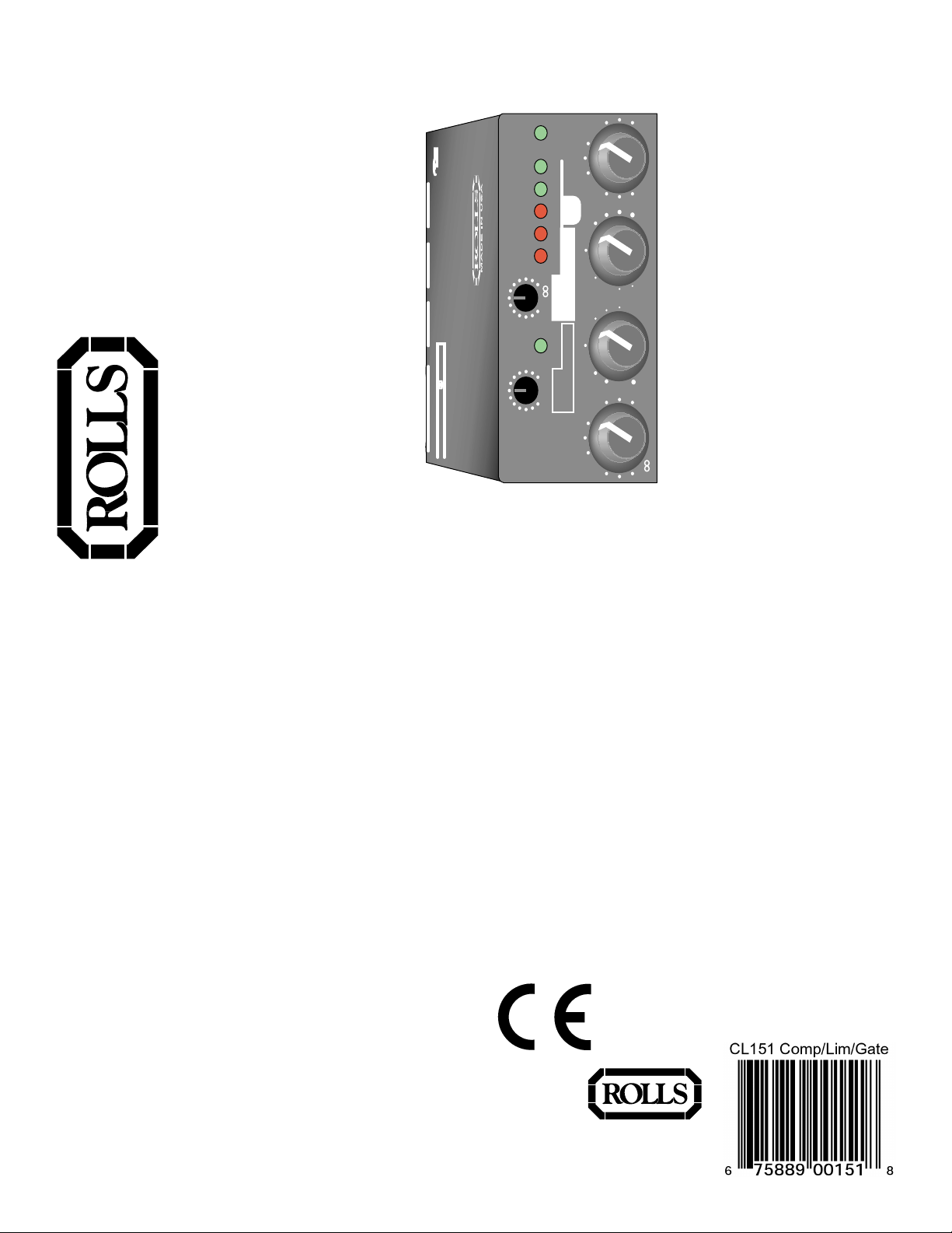
FRONT PANEL
SPECIFICATIONS
Max Input: XLR: -10 dBm Balanced
1/4": +14 dBV Balanced
Max Out: +14 dBV Balanced
Noise Floor: -72 dBV, Out Level Min, Gate Off
Phantom Pow er: 12 VDC
Frequency Response: 10 Hz - 30 kHz, +0 -3 dB
Gate Release Time: 150 mS - 1 S
Gate Attack Time: 5 mS
Comp Attack Time: 5 mS
Comp Release Time: 800 mS
Po wer: 12 VDC 150 mA adapter (center negativ e)
Weight: 1 lbs. (.45 Kg)
Size: 4.15" x 2.46" x 1.55"
0
-
INPUT
GATE
1 Sec .15 1:1
GATE
THRESHREL
-10
+10
-20
+20
-30
COMP
0
+12
off
GAIN REDUCTION
:1
24 10
THRESHRATIO
-10
-20
-30
0
+10 -10
31
dB
OUTPUT
0
.5
PWR
+10
+20
INPUT: Adjusts the amount of input signal to the CL151, from no signal to +20
dB.
GATE REL: This control adjusts the amount of time taken for the gate circuitry
to "close" or mute the output, after the signal lev el has dropped below the
gate Threshold level.
THRESH: Sets the point at which the input signal must surpass to "open" the
gate circuitry or allow signal to pass to the output.
GATE LED: When lit, indicates that the gate is "closed" or the output is muted.
COMP RATIO: This control sets the signal to compression r atio. This ratio
relates to the amount of increase of input compared to output signal. Thus, at
a 1:1 ratio, a 1 dB increase of input signal will result in a 1 dB increase of
output signal. At 2:1, a 2 dB increase of input signal will result in only 1 dB
increase of output signal. At 8:1, an 8 dB increase of input signal will result in
a 1dB increase of output signal.
THRESH: Sets the point that the input signal must reach f or compression to
begin.
GAIN REDUCTION LEDs: This LED ladder indicates the amount of signal
compression, or gain reduction.
OUTPUT: Adjusts the amount of o v erall output signal from the CL151.
PWR: Indicates that the CL151 is connected to the pow er source, and the unit
is on.
1
6
Page 3

PHANTOM
POWER
off
on
MIC IN LINEINSIDE
CHAIN
LINE
OUT
DC IN
12 VDC
+
-
CL151
GLC
Gate
Limiter
Compressor
SCHEMATIC
REAR PANEL
MIC IN: Balanced XLR jac k, f or connection to
any standard dynamic or condenser micro-
1
Rev:
A
O U T
R 5 8
1 K
J 5
G A T E C L O S E D
D 9
L D R R
1 0 K
VCC
R 2 4
R 2 3
VCC
R 2 2
VCC
R 2 0
1 0 K
R 1 8
1 2 0 P F
C 9
P 3
P 1 0 0 K
VCC
VCC
C 6
4 7 0 P F
R 1 2 1 0 K
3 3 2 1 %
H D 3
R 5 9
H 1 C
VCC
3
C 4
4 7 U
C 3
4 7 U
R 1
4 . 7 K
R 2 6
7
4 7 K
L M 3 5 8
R 2 5
8
U 2 B
VCC
1 0 0 K
5
6
C 1 1
1 0 U
1 0 0 K
R E L E A S E
P 6
P 1 0 0 K
Q 3
1 0 K
2 N 3 9 0 4
R 2 1
2 2 K
C 1 0
. 0 4 7
Q 2
2 N 3 9 0 4
2 K
1 0 0 K
R 1 9
1
L M 3 5 8
R 1 7 1 0 0 K
C 8
1 U
A 0 5
3 3 K
R 1 4
4 5 6 0
H D 3
H 1 A
H 1 B
2
R 2
3
4
U 2 A
2
3
R 1 6
1 0 K
R 3 6
1 K
C 3 1
47U
2 K
R 1 5
Q 1
VB
C 7
4 7 U
D 7
4 7 K
R 1 3
1 0 U F
C 2 7
1
4
U 1 A
R 8
1 0 K
2
3
H D 3
C 5
3 3 2 1 %
4 7 0 P F
1
R 7
C 2
4 7 U
4 . 7 K
C 1
4 7 U
J 3
X L R F P C
1 2
R 4 0
R 3 9
C 1 9
2 7 P F
R 3 7
4 . 7 K
O U T L E V E L
P 1
P 1 0 0 K
R 2 7 1 M
D 1 0
C 1 2
5 0 3
R 3 4
VCC
R 3 1
VCC
P O W E R
L D R R
VCC
1 2 0 P F
C 1 3
R 1 0 1 0 0 K
VB
P 4
P 1 0 0 K
R 9 1 0 K
I N L E V E L
R 4
1 0 K
R 3
1 0 K
J 2
P H O N E 1 / 4
P H O N E 1 / 4
4 7 U
C 2 0
R 4 1
1 K
4 7 K
VCC
R 3 8
4 . 7 K
R 3 5
VB
1 N 4 1 4 8
2 2 K
3 3 K
15
L M 1 3 6 0 0
1 0 K
14
L M 1 3 6 0 0
2
11
3
VB
4 5 6 0
8
VCC
VB
1 0 0 K
7
ROLLS CORPORATION
4 5 6 0
8
U 4 B
6
5
1 8 K
223
Q 4
3
1
J 1 1 3
1 U
C 1 8
1
1
1 U
1 2 0 P F
C 1 7
9
10
U 3 B
13
8
7
U 3 A
4
R 2 8
C 1 4
7
U 1 B
6
1 0 K
R 1 1
R 6
R 5
C 1 5
4 5 6 0
U 4 A
2
3
R 3 3
12
16
6
1 0
R 3 2
5
1
2 2 K
1 U
5
1 M
1 M
T H R E S H O L D
4
VB
1 0 K
Q 5
2 N 3 9 0 4
VB
VB
R 4 9
3 3 0 K
VB
R 5 2
R 5 4
R 5 5 R 5 3
R 5 6
VCC
S I D E C H A I N
J 4
P H O N E 1 / 4
1 0 K
R 4 2
C 2 1 1 U
2
P 2
1 0 0 K
3 3 K
R 4 3
1 U
C 2 3
R 4 6
R 4 7
3
VB
4
U 5 A
L M 3 5 8
1
R 4 4
1 0 K
C 2 2
2 7 P F
VB
R 4 5
1 0 0 K
6
5
8
1 0 0 K
VCC
1 0 K
2 N 3 9 0 4
6 . 8 K
R 5 1
1 N 4 1 4 8
VB
U 5 B
L M 3 5 8
R 4 8
7
1 0 0 K
1 0 U
C 2 4
1 N 4 1 4 8
D 1 1
1 0 U
C 2 5
Q 6
R 5 0
1 N 4 1 4 8
D 1 2
Q 7
R A T I O
P 5
C 1 0 K
1
2
3
4
5
6
7
8
9
1 0 K
R 5 7
5968 SOUTH 350 WEST
C 3 0
VCC
C 2 9
VCC
VCC
3
O
7 8 1 2
1 0 0 K
U 6 B A 6 1 4 4
I
1
231
J 1
I N 9 - 1 5 V A C / V D C
D 2
D 3
D 4
D 5
D 6
G A I N R E D U C T I O N
Sheet 1 of
SALT LAKE CITY, UT 84107
CL151.SCH
Document Number:
22-Mar-2001Date:
Ba
COMPRESSOR LIMITER GATE CL151
Title:
5 0 3
5 0 3
G
J A P D C
phone.
LINE IN: Balanced 1/4" TRS jack for connection to balanced or unbalanced line level
signals.
SIDE CHAIN: 1/4" TRS jack for connection via
TRS insert cable to a device such as an
equalizer or other device, f or direct access to
the CL151 detector circuitry .
LINE OUT: Balanced 1/4" TRS jack for
connection to a mixer's line input or to an
amplifier.
DC IN: F or connection to the Rolls PS27 12
VDC, 150 mA power supply; outside of the
barrel is positive.
SIDE PANEL
PHANTOM PO WER: Jumper header for connecting 12 VDC phantom pow er
to the XLR Mic Input. Phantom po wer is engaged b y carefully remo ving the
jumper, and reconnecting it to the pins to w ard the CL151 controls.
For reference only .
25
Page 4

CONNECTION AND OPERATION
DC IN
LINE
12 VDC
OUT
dB
0
CL151
-10
.51310
OUTPUT
0
+
-
PWR
+10
+20
-
0
PHANTOM
POWER
Gate
Limiter
Compressor
INPUT
MIC IN LINE
off
on
GLC
GATE
1 Sec .15 1:1
GATE
THRESHREL
-10
+10
-20
-30
+20
IN
0
off
COMP
-20
+12
-30 +10
SIDE
CHAIN
GAIN REDUCTION
:1
24
THRESHRATIO
-10
The example abov e shows connection of a microphone. If the microphone
requires phantom power , mak e sure the Phantom Power jumper is connecting
the two pins closest to the front panel. Connect the output of the CL151 via a
balanced or unbalanced 1/4" plug to the input of a mixer or amplifier .
Begin adjustments by setting the INPUT and OUTPUT lev els at O (about 10
O'clock). This setting is for "unity gain".
Set the gate THRESH f or "off", the COMP RATIO for 1:1, and the compressor
THRESH for +10. These initial settings essentially bypass the gate and
compressor circuits.
The gate THRESH control, after being turned slightly counterclockwise from
the "off" position, goes to its maximum level. This means it requires a higher
signal level to "open" the gate . As the gate THRESH control is turned counterclockwise, a lower and low er signal is required to open the gate.
The gate REL (release time) control sets the amount of time taken for the
gate to "close" after the signal drops below the THRESH level. For e xample ,
the CL151 will continue passing a sustaining note until the lev el drops below
the THRESH le v el, and the REL time has passed.
USING THE SIDE CHAIN
To access the compressor detector circuit directly , Rolls has included a Side
Chain jack. The Side Chain works somewhat like an effects loop , with a send
and return point. A 1/4" Tip-Ring-Slee v e "Insert Cable" is required to utilize the
Side Chain. See the picture belo w.
SEND
Connects to tip
T o SIDE CHAIN
RETURN
Connects to ring
The plug connected to the Tip is the "Send" which will connect to the Input of
the signal processing device, and the Ring is the "Return" which connects
directly to the detector (compression control) circuit.
Side Chain circuits are often used in "ducking". Duc king is momentarily
lowering one signal under another signal. F or e xample , y ou ma y wish to
automatically lower a music signal under a paging microphone signal, then
have the music return to normal level after the page is over. This would be
accomplished by running the music into the compressor, and ha ving the page
signal connect into the Side Chain return. The page signal must also be
connected to the main mixer or amplifier as well. When the paging signal
begins, its signal goes to the main mixer and the Side Chain circuitry. The
music is compressed or "ducked" under the page.
The compressor RATIO and THRESH controls work together to control the
amount of compression, and the point at which compression begins respectively. Decreasing the THRESH control lo wers the amount of signal required
to begin compression - so it compresses sooner. This works with the RATIO
control which, when increased, increases the amount of compression.
3 4
 Loading...