

Page 1

BATTERY USER
MANUAL
Recommended installation, charging and maintenance
procedures for Rolls deep cycle Flooded, VRLA AGM
& OPzV GEL batteries.
Page 2

FLOODED
AGM
GEL
RENEWABLE
ENERGY
MARINE
MOTIVE
POWER
Page 3

TABLE OF CONTENTS
02 Equipment & Safe Handling Procedure
02 Inspection
03 Quick Ch
03 Disposal Procedure
04 Installation
04 Battery Orientation
04 Cable Sizing
05 Warning
05 Terminals
06 Parallel & Series Connections
09 Inspection & Initial Charge of Flooded Lead-Acid Batteries
10 Rolls Flooded Lead-Acid Battery Charging
10 Bulk Charge, Absorption Charge
11 Absorption Charge Time - Flooded
11 Float Charge, End Amp or Return Amps
12 Low Voltage Disconnect
13 Rolls Flooded Battery Charge Voltage Parameters
14 Temperature Compensation & Sensor Installation
15 Specific Gravity
16 Battery Maintenance & Storage
16 Electrolyte - Adding Distilled Water
18 Cleaning Vent Caps
19 Equalization, Corrective Equalization
21 Preventative Equalization & Frequency
23 Rolls VRLA AGM Battery Charging Instructions
24 VRLA AGM Absorption Charge Time
24 Rolls VRLA AGM Battery Charge Voltage Parameters
27 Rolls OPzV GEL Battery Installation & Charging
27 Rolls OPzV GEL Battery Charge Voltage Parameters
29 OPzV GEL Absorption Charge Time
31 Renewable Energy Applications - Off-grid & Grid-tied
37 Warranty
39 Lead-Acid Battery Glossary
41 Troubleshooting & Frequently Asked Questions
46 Contacts
eck List
1
Page 4

Rolls Battery has been manufacturing deep cycle lead-acid batteries since 1935.
Experience and commitment to quality has helped us achieve an unmatched
reputation in the industry. Our goal is to provide our customers with a premium
product providing dependable performance and long-lasting cycle life. This manual
provides the recommended setup, charging, Equalization and preventive maintenance
procedures necessary to maximize the life of your Rolls batteries. If you have batteryrelated questions beyond the contents of this manual, we encourage you to visit our
online Technical Support Desk (support.rollsbattery.com) for additional information
or file a support ticket and our Technical Support team will be happy to assist you.
EQUIPMENT & SAFE HANDLING PROCEDURE
• Goggles, rubber gloves & rubber boots
• Distilled water
• Baking soda, soda ash
To prevent injury, always wear acid-resistant clothing, PVC gloves, goggles and
rubber boots. Flooded batteries must be maintained in an upright position at all times.
Always have plenty of water and baking soda on hand in the event of an acid spill
during transport.
• hydrometer, refractometer
• voltmeter, ammeter
• battery charger
INSPECTION
When receiving shipment of your batteries, it is important to thoroughly inspect each
pallet, battery and packaging. Before signing acceptance of the shipment, remove the
shrink-wrap from the pallet and inspect each battery for damage (i.e. cracks, dents,
punctures, deformations, acid leaks or other visible abnormalities).
Do not accept shipment if the batteries appear to have been damaged in any way.
Confirm that connection terminals are secure and clean. If the battery is dirty, or if
any minor amount of acid has spilled onto the case due to loose bayonets, refer to the
cleaning instructions in this manual to properly neutralize and clean as necessary. Wet
pallets or signs of acid leak on or around the batteries could indicate shipping damage
or improperly sealed battery casing. Perform a voltage check to confirm the battery
polarity and marking of the terminals are accurate.
In the event of a suspected leak or damage, do not accept the shipment.
Contact your battery retailer or Rolls Battery to determine whether the batter(ies)
require replacement.
Battery shipments which are known to be damaged, but accepted, will not
be replaced under the terms of Rolls Battery manufacturer warranty.
2
Page 5

QUICK CHECK LIST
SHIPPING/RECEIVING (MUST INSPECT PRIOR TO DRIVER RELEASE!)
• All parts are included
• No acid spill
• No visual damage to the batteries
• Verify electrolyte levels
INSTALLATION
• Protective equipment should be worn
• All electrical components should be turned off
• Acid spill cleanup material should be readily available
INITIAL CHARGE
• Verify electrolyte levels (add distilled water as necessary)
• Measure specific gravity
• Set up battery charge voltage/current limits
GENERAL
• Safety first!
DISPOSAL PROCEDURE
Batteries must NEVER be disposed of in household waste. To reduce environmental
impact, bring your spent lead-acid batteries to a certified recycling depot. Lead-acid
batteries are 97% recyclable and are the most recycled consumer product in the world.
Closed-loop manufacturing and recycling programs allows nearly all of the components
to be recycled or re-purposed. A credit by weight for lead may be offered by recycling
depots or facilities for spent batteries.
When processed safely, recycling batteries reduces the release of lead to the
environment and conserves natural resources. Recycled lead production takes only
35-40% of the energy necessary to produce primary lead from ore. Lead may
be recovered and re-purposed multiple times.
For more information on lead-acid battery recycling, visit https://batterycouncil.org
3
Page 6

INSTALLATION
Rolls deep cycle batteries are manufactured for use in a variety of applications. In all
cases, it is important that the battery is installed securely, free of contaminants and
that all connections are in good contact with the terminals.
For all Rolls models it is recommended that the batteries are separated 2.5cm-7.5cm
(1"-3”) inches apart to allow proper airflow, cooling and ease of maintenance. Flooded
batteries should be installed in a temperature-controlled room or enclosure with
adequate battery spacing to allow cooling and/or insulating to prevent freezing in very
cold temperatures. Excessive heat or cold temperatures will result in the reduction of the
overall cycle life. Batteries should never be installed in a completely sealed enclosure.
Enclosures for Valve Regulated batteries (VRLA such as sealed AGM & GEL models,
should, at minimum, be passively ventilated. Enclosures for Flooded models should
be actively ventilated with both positive and negative airflow installed to remove and
replace any hydrogen gas generated during charging (produced as cell voltage reaches
2.25 VPC or above. Every effort should be made to avoid hydrogen accumulation as
concentrations in excess of 2-4% may ignite with electrical spark and are explosive.
The outer container of Rolls Series 5000 models is molded with handles to safely lift
and transport the battery. This also provides structural support to maintain cell shape
and offers an added layer of protection. Rolls individual 2V industrial cells are typically
housed in steel or plastic trays. These cells must be properly supported on each side
to protect against puncture, prevent bulging and should not be lifted by the terminals
as this may damage the posts or compromise the cells internally. When moving,
support straps should be used to safety and securely lift the cell from the bottom.
Dual-container models are better-suited and strongly recommended over industrial
cells for use in Renewable Energy and Marine applications as the stand-alone case
design allows easier transport and the ability to install the batteries with adequate
spacing for airflow. Series 5000 dual-container models are backed by a 5-year
(60 month) full replacement warranty, offering an additional 2 years of coverage over
the equivalent 2V industrial cell.
BATTERY ORIENTATION
Flooded lead-acid batteries must be kept in an upright position at all times. The electrolyte
in a Flooded battery may spill if tilted more than 20 degrees. Rolls VRLA AGM & OPzV GEL
batteries may not be mounted upside down or horizontally on the end (shortest side of the
case. Rolls VRLA AGM batteries may be mounted upright or horizontally on the side (longest
of the battery case. Rolls OPzV GEL models must be installed vertically unless otherwise
specified. Special order models compatible with horizontal installation are available. Use
caution not to cover or apply pressure to valves located on the top of the batteries when
using strapping to install or secure cells as damage may occur.
Rolls OPzV GEL models compatible with horizontal installation as well as racking systems
are available upon request. Please contact your Rolls Battery distributor or dealer for
more information.
4
Page 7

CABLE SIZING
Cabling should be proportionate to the amperage of your system. The following table
notes the maximum current carrying capacity based on cable gauge. Battery cables
should be selected allowing a maximum voltage drop of 2% or less across the entire
length of the cable. Interconnection cables (battery to battery) should also be sized
at the same gauge and of equal length between connections. When choosing
interconnect cables or custom bus bars, size to allow adequate spacing between
batteries for airflow as outlined above.
TABL E 1: Wire gauge sizing by amperage
WARNING
The charger cabling should be insulated and free of damage. The cable connectors should
b
e clean and properly mated with the battery terminals to ensure a snug connection.
Loose or overtightened connections may cause high resistance. The result is an
unwanted voltage drop as well as excessive terminal heating, causing the terminal to
melt or even catch fire. To limit the possibility of damage or fire, use a torque wrench
to properly adjust terminal connections during your regular maintenance schedule.
Undertorqued connections may become loose as the terminal warms & cools causing
possible arching and risk of spark. Over-torqued connections may indent, crack or
bend the terminal and/or washers or terminal connectors. Terminal damage from
overtorque is often irreparable. The use of an Infrared (IR temperature) sensor may
assist in identifying poor connections when testing under load or during charge.
Using an Infrared (IR) temperature sensor may assist in identifying poor connections
when testing under load or during charge.
Connections which have overheated and/or developed problems will often be welded
to the terminal. Visual inspections may not always detect poor connections. It is
recommended that terminal connections are disconnected, cleaned and re-torqued
periodically as part of the regular maintenance routine.
TERMINALS
Inspection of battery terminal connections is also important. Loose connections
may result in ignition of hydrogen gases or cause a short, melting the terminals.
It is important to inspect, disconnect, clean and properly torque these connections
on a regular basis. Use a proper torque wrench, noting the required torque setting
for the particular terminal.
5
Page 8
Flooded LEAD-ACID TERMINALS
Terminal connections should be tightened to 25 ft/lbs or 33 N.m for all Flooded
Series 4000, 4500 & 5000 models.
VRLA AGM & OPzV GEL TERMINALS
Torque settings vary by terminal type, please refer to the chart below and/or
provided specifications. Contact Rolls Battery Technical Support if your terminal
type is not listed.
AGM-S & AGM-R Terminals Torque N.m
Button Terminal (M8) 9.6-10.7
Button Terminal (M10) 12.2-14
AP 5.6-7.9
LT 9.6-10.7
DT (AP and stud terminal) 5.6-7.9
M6 (TP08) 3.9-5.4
M8 (TP08) 9.6-10.7
OPzV GEL Terminals Torque N.m
M10 Female 20-22
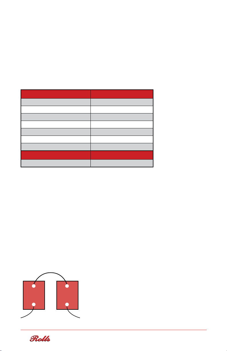
PARALLEL & SERIES CONNECTIONS
Applications often demand more voltage or more ampere capacity than the
capacity of one battery. By connecting multiple batteries of the same make/
model/capacity in series, parallel or series parallel configurations, output voltage
or battery bank amperage may be increased as needed.
To increase voltage, batteries are connected in series. Capacity of the battery
bank remains the same as voltage increases. To increase the available amount
of current and capacity, batteries are connected in parallel. In this situation it
is best to use lower voltage, higher capacity cells to minimize the amount of
parallel strings.
To increase voltage, connect the batteries in series as shown in Figure 1.
-
+
FIGURE 1:
Voltage Increase
+
-
6
Page 9
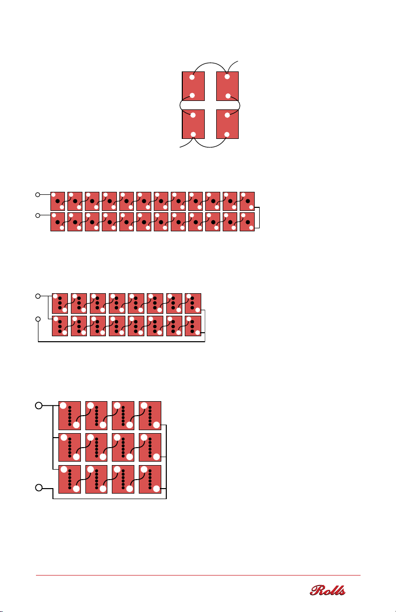
To increase capacity and voltage, connect the batteries in series parallel
-
++ + + + + + + + + + ++
++++++ +++++
---
+
++ + + + + + ++
++ + ++
++
++
as shown in Figure 2.
EXAMPLE:
Battery = 6-volt (S6 L16-HC)
Battery Voltage = 6V each
Battery Capacity = 445 AH each
+
-
+
-
++
FIGURE 2:
Voltage/Capacity
Increase
System Voltage = 12V System
Capacity = 890 AH total
-
-
EXAMPLE:
Twenty-four (24) 2-volt batteries at 2527 AH each = 2527 AH at 48 Volts
- - - - - - - - - - --
- +
-
- -
---- ---
FIGURE 3:
Single Series String
-
+ “Best Option”
EXAMPLE:
Two (2) strings of eight (8) 6-volt batteries at 445 AH each
= 2 x 445 AH at 48 Volts = 890 AH at 48 Volts
- - - - - --
++++++ +
-
-
+
---- ---
-
FIGURE 4:
Two Parallel Strings.
Series/Parallel
EXAMPLE:
Three (3) strings of four (4) 12-volt batteries at 371 AH each
= 3 x 371 AH at 48 Volts = 1113 AH at 48 Volts
- --
++
---
-
Three Parallel Strings.
Series/Parallel
-
++
FIGURE 5:
-
NOTE: Connecting more than three (3) series strings in parallel is not recommended. Multiple
-
--
-
parallel connections increase resistance between batteries and strings, causing an imbalance of
charge and discharge currents and may result in cell damage or premature failure which is not
covered under Rolls Battery manufacturer warranty.
7
Page 10

FLOODED
LEAD-ACID
BATTERIES
Page 11

INSPECTION & INITIAL CHARGE OF FLOODED
LEAD-ACID BATTERIES
WARNING
• ALWAYS WEAR THE PROPER PERSONAL PROTECTIVE EQUIPMENT
(GOGGLES, GLOVES, CLOTHING) WHEN HANDLING FLOODED BATTERIES
AND ELECTROLYTE.
• WET BATTERIES MUST BE FULLY CHARGED BEFORE BEING DELIVERED
TO THE END USER.
• UNLESS INSTRUCTED BY ROLLS TECHNICAL SUPPORT, NEVER ADD ACID
TO THE BATTERIES AT ANY TIME. USE DISTILLED WATER ONLY.
FAILURE TO
AND WILL VOID WARRANTY.
A battery may not be fully charged when received. An initial charge brings the battery
to an operational state. Before charging, inspect for physical damage, check polarity
and electrolyte levels in each cell. Ensure the electrolyte (liquid) covers the plates
completely. It is normal for electrolyte levels to lower as the battery case will relax
(bulge) slightly after filling. If the plates are exposed, add distilled water until all are
just submerged. It is important not to overfill each cell as the electrolyte level will
rise during the charging process. Charge voltages are indicated in Table 2 (a & 2 (b
Flooded Charging Parameters.
INITIAL INSPECTION & CHARGING
1. I nspect the batteries for damage. Important: read all warning labels on batteries
b
efore proceeding.
2. Flooded batteries are fully charged and tested before shipping. However, deep cycle
batteries will self-discharge when not in use during transportation and storage. Upon
installation, the initial charge brings the battery to an operational state. Before this
charging process, electrolyte levels should be checked, making sure the plates are
covered in each cell. If required, add distilled water until the plates are fully submerged.
It is important not to overfill as the electrolyte level will rise slightly during charge.
3. Check for correct polarity. Attaching the positive and negative voltmeter lead to the
positive and negative battery terminal should provide a positive voltage reading. If it is
negative, a reverse polarity condition exists and you should contact your dealer or
Rolls Battery Technical Support to advise.
FOLLOW THESE INSTRUCTIONS MAY RESULT IN MALFUNCTION
4. Place batteries on charge. Please see Table 2 (a & 2 (b Flooded Charging Parameters
for required charging parameters. Do not let the cell temperature exceed 52°C (125°F). If
the temperature becomes excessive or the cells begin to gas vigorously, reduce the
rate of charge. Continue charging until all cells reach the specific gravity of the filling
acid. All cell specific gravities should be even (1.260-1.280) when resting at full charge.
9
Page 12

FLOODED LEAD-ACID BATTERY CHARGING
I
NITIAL CHARGE
Although all Rolls batteries are tested and charged prior to shipping, batteries will
self-discharge when stored and not in use. Upon installation, the initial charging
may take 10+ hours or more depending on the size of the battery bank and charge
current. Once the battery is fully charged, recheck the electrolyte level in the cell.
The fluid should be 6-12mm (1/4”-1/2”) below the vent tube on each cell as shown
in Figure 7. Carefully add distilled water to adjust as needed.
MULTI-PHASE CHARGING
The most common charge method for Flooded deep cycle batteries is a three-phase
charge cycle with periodic equalizations. Always be sure to follow the recommended
charging parameters as these will vary. Often, pre-programmed default settings are
not in line with the battery manufacturer's recommended voltage settings. Using these
may result in damage or battery failure which is not covered under the manufacturer
warranty. Refer to the charger manufacturer for specific programming instructions.
BULK CHARGE
The first of the three-phase charging process is the Bulk charge. During this stage the
maximum amount of current flows into the battery bank until a desired programmed
voltage is reached. For Flooded models, the recommended Bulk charge current is 10%
of the AH capacity of the battery bank, based on the 20 Hr AH rate (C/20) (min 5%, max
20%). Higher charge current may cause the battery bank to overheat or damage the
cells. A lower charge current may be used, however, this will prolong the required charge
time and increase the potential for sulfation build-up. Bulk charge voltage set points are
outlined in Table 2 (a & 2 (b Flooded Charging Parameters.
ABSORPTION CHARGE
The second and most important phase of the charge cycle is the Absorption charge.
Bulk charge typically charges the battery bank to approx. 80% SOC. Once reached, the
charger will then switch to the programmed Absorption voltage to complete the charging
cycle. Most three-phase chargers include an Absorption charge time setting allowing
the user to program the duration of time needed to reach a full state of charge (100%
SOC). To set the Absorption charge time, a calculation is done using the 20 Hr AH
rating of the battery bank (C/20) and the available charge current and/or max charger
output. As the battery bank nears 100% SOC, internal resistance in the battery
increases and charge current begins to decrease. It is assumed that over the time of the
Absorption charge that 50% of your maximum charge current will be available (factored
into the equation) 0.42 = (20%/50%) + 5%. 5% is added due to losses.
10
Page 13

ABSORPTION CHARGE TIME - FLOODED
Where : T = 0.42 x C /I
T = ABSORPTION CHARGE TIME
C = 20 hr RATED CAPACITY (total battery bank)
I = Charging Current (Amps)
(recommended 10-20% of C/20 discharge rate for Flooded models)
0.42 = ( 20%/50%) + 5% (5% is added due to losses)
EXAMPLE:
2 strings of 6 Volt 6 CS 25P models
20 hr AH rate = 853 AH x (2 strings) = 1706 AH
I = 10% of 1706 AH = 170 Amps (10-20%, 170-340 Amps)
T = 0.42 x 1706/170 = 4.2 hrs
However, if maximum charger output is 120 Amps, 120 is used.
T = 0.42 x 1706/120 = 5.97 hrs
NOTE: Actual Amp output from the charge source(s) should be used. Maximum
charger output applies when the generated output meets or exceeds this threshold.
FLOAT CHARGE
When the Absorption charge phase has completed and the batteries have reached
100% SOC, the charger will continue to output at a lower voltage setting known as
Float. Float voltage maintains the battery bank at a constant 100% SOC until the
charge output diminishes (ex: solar) and/or a load is applied which begins to discharge
the battery bank. To prolong battery life, the Float settings on the power supply
should be adjusted to the voltage indicated in Table 2 (a & 2 (b Flooded Charging
Parameters. Higher or lower voltage settings may result in unnecessary overcharge
or sulfation buildup.
END AMPS OR RETURN AMPS
As batteries near full capacity, charge current decreases. End Amps or Return
Amps refers to the lowest output of current (Amps) running to the batteries once
they have reached full capacity. Some charges will measure the actual current
output. If the charge current drops to the End Amps or Return Amps set point before
the programmed Absorption time has completed this will trigger the charger to shut
off or switch to the Float voltage phase, maintaining the bank at 100% SOC.
End Amps or Return Amps for new Series 4000 Flooded models should be set at
2-3% of the 20 Hr AH rating (C/20) of the battery bank.
NOTE: Rolls 4500 & 5000 Series models with Advanced NAM carbon additive may
see higher End Amps or Return Amps values as the cells are less resistant to charge
and current output will remain slightly higher at 100% SOC. A set point of 2-5% may
be used with these models. Adjustments may be required when these are used to
replace other Flooded models.
11
Page 14

WARNING: The End Amps or Return Amps setting combined with a sulfated battery
may confuse the charger, cause a state of charge reset prior to actually reaching 100%
SOC. Check specific gravity regularly to confirm the battery bank reaches 100% SOC
as this set point may require adjustment.
LOW VOLTAGE DISCONNECT (LVD OR LVCO)
Many charging systems offer the ability to program a Low Voltage Disconnect (LVD)
or Cut Off (LVCO) which triggers an alternate power source (often a generator) to turn
on and begin charging the battery bank. When the programmed low voltage setting
is reached, the system initiates the charge source which then safeguards from
overdischarge. By default, this may be set by the charger manufacturer at 1.75 volts
per cell (VPC). Always verify the default settings and adjust as required.
LVD/LVCO setting is often a personal preference. Deep cycle batteries are intended
to be discharged no more than 50%. Allowing the battery bank to discharge to a lower
voltage will reduce over all cycle life. Alternatively, a higher set point may result in more
frequent use of the alternate charging source (ex: generator) when discharge reaches the
low voltage cut-off. To maintain cycle life and prevent heavy discharge, Rolls recommends
setting LVD/LVCO between 1.85-1.95 volts per cell (VPC). This may be adjusted up or
down, depending how often you wish to run the alternate charging source (generator or
alternative power) when the voltage of the battery bank reaches the programmed set point.
WARNING: LVD/LVCO only cuts off the draw from the inverter/ charger. It does not
disconnect all loads from the battery bank. A prolonged draw will eventually lead
to overdischarge and possible battery failure or damage.
OTHER CHARGER MODES
Inverter and charge controller manufacturers may include additional settings. Rolls
recommends contacting the manufacturer for guidance and to better understand how
these settings function. Default settings are typically not in line with the required
charge voltages and time. Charge & Float voltages and Absorption time calculations
are provided by the battery manufacturer and are specific to the make & model.
See Table 2 (a & 2 (b Flooded Charging Parameters.
FLOODED LEAD-ACID BATTERY - CHARGE EFFICIENCY / CHARGE FACTOR
Charge efficiency is a measure of the energy you may take out of a charged battery
divided by the energy required to charge it. Charge efficiency will depend on a number
of factors including the rate of charging or discharging. Charge efficiency for Flooded
deep cycle models is typically 80-85%. This should be reduced 1% per year after the
third (3) year of operation.
12
Page 15
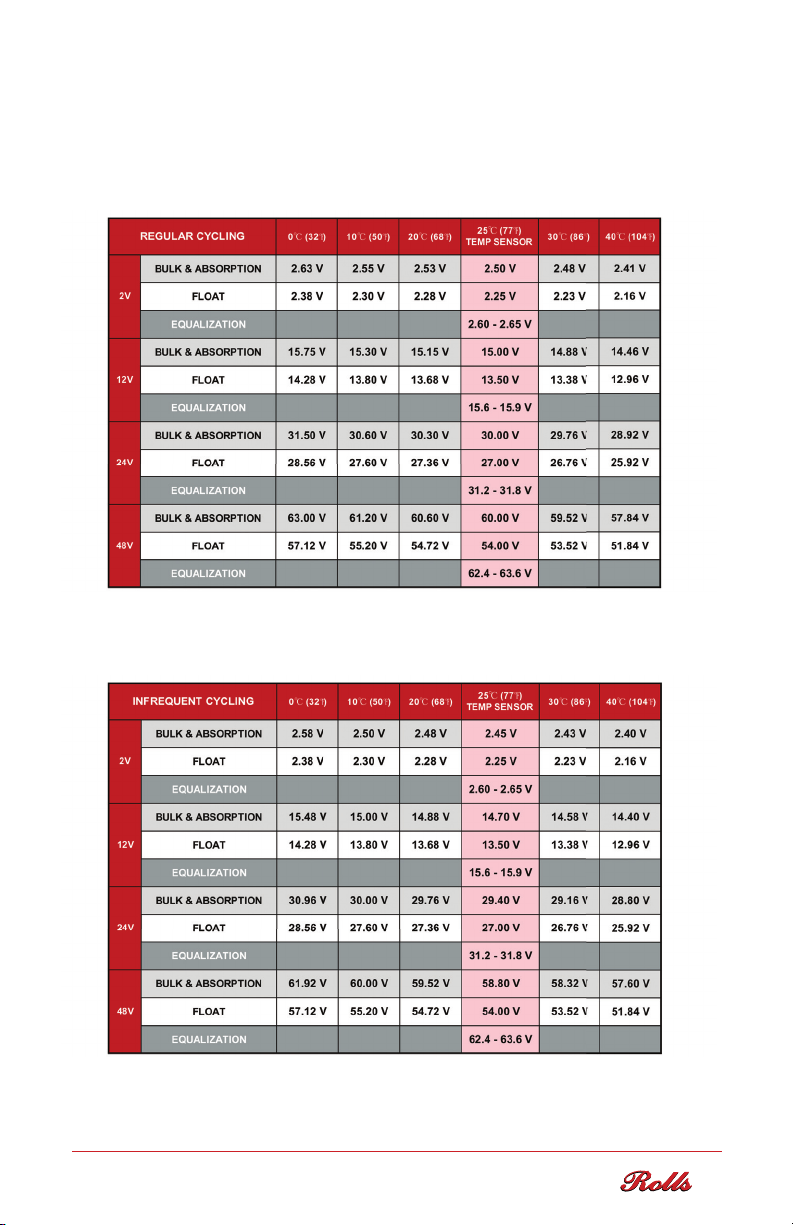
ROLLS FLOODED BATTERY CHARGE
VOLTAGE PARAMETERS
NOTE: Use the highlighted voltage set points when charge equipment is supplied
with a temperature sensor. Set at 5mV/ºC/Cell...(+/- 120mV per ºC from a 25ºC
Delta - 48V System)
TABLE 2 (a): Flooded Charging Parameters: Regular Cycling - daily to 48-hour
cycling (max 50% DOD) with limited charge time (solar). Example: full-time off-grid
applications and Partial State of Charge (PSOC) recovery.
TABLE 2 (b): Flooded Charging Parameters: Infrequent Cycling - infrequent cycling
with grid-connected charging (Marine/RV/Industrial), off-season/part-time off-grid
solar applications or grid-tied battery-backup systems.
13
Page 16

TEMPERATURE COMPENSATION
& SENSOR INSTALLATION
For charge accuracy and safety, many systems use a sensor mounted to the battery to
measure cell temperature and adjust charge voltage accordingly. Temperature sensors
should be installed directly on the side of a cell or battery in the center of the bank
and must be securely mounted below the electrolyte level to determine accurate cell
temperature. See Figure 6 Temperature Sensor below. When using chargers that do not
feature temperature compensation, voltage settings should be monitored and adjusted
based on actual cell temperature. Failure to use or properly install the provided sensor
may cause damage due to over/undercharge which is not covered under Rolls Battery
manufacturer warranty. As a precaution, this sensor may also trigger a programmed
safety charge cut-off as the battery bank should not exceed an operating temperature
of 52ºC (125ºF).
NOTE: FOR ACCURACY, THE TEMPERATURE SENSOR SHOULD NOT BE MOUNTED
TO THE BATTERY TERMINAL OR TOP OF THE BATTERY CASE.
Series 4000, 4500, VRLA AGM & OPzV GEL models – the temperature sensor should
be mounted on a battery in the middle of the string or battery bank. To ensure an accurate
reading of cell temperature, the sensor must be mounted below the liquid level on Flooded
models and not attached to a terminal or top of the battery case as these areas are
generally cooler than the internal cell. For traditional Flooded, VRLA AGM & OPzV GEL
models, Rolls recommends attaching the sensor half way down the side of the battery and/
or 10-12cm (4-5”) from the top of the case for the most accurate temperature reading.
Dual-Container Models – If the battery has a modular, dual-container construction, the
temperature sensor must be mounted directly to the side of an internal cell. To access the
cell, disconnect the terminal connections and remove the outer cover which snaps on
to the case or may use small removable plastic pins. Mount the sensor to the internal
cell and run the connecting cable between the case, being careful not to pinch or damage
the wire when placing the cover back on. Automotive silicone is used to seal around each
terminal to protect against spills, dust & debris. This may be reapplied when the case has
been reassembled.
FIGURE 6:
Temperat ure
Sensor
Dual-Container Models - Remove case cover. Mount sensor to the side of internal
cell below liquid level. Replace the cover and re-seal around terminals with silicone.
14
Page 17

SPECIFIC GRAVITY
The specific gravity of electrolyte in a battery is the most accurate measurement of actual
state of charge. To determine if the batteries have reached full SOC, testing should be done
when the charge cycle has been completed and the battery bank is resting a Float voltage.
The specific gravity (SG) reading should remain constant for 3+ hours for an accurate 100%
SOC reading.
*Test and record specific gravity readings regularly to confirm charging parameters are
properly programmed and to avoid possible over/undercharge, cell damage and/or battery
failure. Rolls Battery provides a Flooded Deep Cycle Battery Maintenance log book
to track these readings and includes reminders to perform regular system inspections.
Request a copy from your Rolls Battery Distributor or Dealer.
Recommended testing: every 45-60 days
Minimum: every 90 days
Routine testing of specific gravity in Flooded models provides an opportunity to quickly
identify any notable changes in battery performance caused by charge-related issues
such as over/undercharging, sulfation buildup, capacity loss or cell/battery performance
or failures. Regular testing and tracking offers peace of mind and is expected as part of
the normal maintenance procedures. When monitored, necessary system adjustments
may be made to quickly correct & prevent any further issue or damage.
NOTE: Failure to adhere to ongoing maintenance requirements, including routine testing
and logging of specific gravity and voltage readings, may result in denial of a filed warranty
claim where the performance history and cause of cell/battery failure cannot be determined.
% Charge Specic Gravity* (SG)
100 1.255 - 1.275
75 1.215 - 1.235
50 1.180 - 1.200
25 1.155 - 1.165
0 1.110 - 1.130
TABLE 3: Specific Gravity vs State of Charge @ 25°C (77°F)
NOTE: Specific Gravity is dependent on the electrolyte temperature. These values are
for a temperature of 25°C (77°F). To adjust, add/subtract 0.003 for every 5°C (10°F)
increase/decrease.
15
Page 18

Electrolyte should be kept
at 1/2” below vent tube.
Electrolyte
level
Open cell
1/4” - 1/2”
Maximum electrolyte level specified
by the battery manufacturer
BATTERY MAINTENANCE & STORAGE
Batteries should be kept clean at all times. If installed or stored in a dirty location, regular
cleaning should be performed. Before doing so, assure that all the vent caps are tightly
fastened. Using a solution of water and baking soda (100g per litre), gently wipe the battery
and terminals with a damp sponge, then rinse with water and wipe dry.
A common cause of failure with Flooded battery banks is poor maintenance. Systems are
often professionally installed and maintenance left to homeowners who are unaware of
the requirements or simply choose not to complete the proper maintenance procedures. To
maintain cycle life and protect your investment, Flooded batteries should be checked regularly
and topped up with distilled water as needed. Customers will often neglect this for extended
periods of time, and when doing so, over-water the cells resulting in loss of electrolyte,
overflow during charging and/or corrosion issues. Failing to top up cells may result in plate
exposure, overheating and possible explosion.
ELECTROLYTE - ADDING DISTILLED WATER
Only distilled (preferred), deionized or reverse osmosis water should be used in Flooded
battery cells. Improper watering may cause internal cell damage. Test water to confirm
a PH reading of 7 or less and no Total Dissolved Solids (TDS < 5 PPM).
NOTE: Do not add sulfuric acid to Flooded battery cells during normal top up. In the case
of accidental spill, premixed electrolyte (1.265 S.G.) may be used to refill cells.
FIGURE 7:
Electrolyte level
6mm - 13mm
1/4" - 1/2"
Electrolyte level should
be kept below vent
tube to prevent overflow
during charge.
CAUTION: Do not add water or electrolyte to cells before initial charging unless plates are
e
xposed. If so, add distilled water until plates are submerged. Please contact Rolls Technical
Support if you have any questions or concerns.
NOTE: If the battery cells require watering more than once every two (2) months the
programmed charging voltages may be too high. Adjust and monitor accordingly. If a particular
cell requires significantly more water than others this may be a sign of charge imbalance in the
battery bank caused by resistance and/or cell failure. Typically, Series 4000 & 4500 models will
require watering every 30-60 days. Series 5000 batteries generally require watering every
60-90 days as these models are designed with a higher electrolyte reserve allowing longer
watering intervals. Frequency may vary considerably due to operating temperature, depth of
discharge, cycle frequency and humidity.
16
Page 19

MAINTENANCE SCHEDULE
For the first 12 months of usage, the following tests should be completed:
MONTHLY
• Measure and record resting/loaded voltage
• Check electrolyte levels and top up with distilled water as necessary
• Test and record specific gravity measurements in Float charge
• Record ambient temperature where the batteries are installed
• Inspect to ensure temperature sensor is securely attached
• Inspect cell integrity for corrosion at terminal, connection, racks or cabinets
• Check battery monitoring equipment to verify operation
QUARTER LY
• Test Ventilation
• Check terminals/connections, remove corrosion and properly re-torque
• Check for high resistive connections
• Check cabling for broken or frayed cables
• Verify Charge Output, Bulk/Absorption voltage of Inverter/Charge Controller
• Check cells for cracks or indication of a possible leak
• Check Ground connections
Deep cycle batteries will increase in capacity during the initial break-in period
of 60-90 cycles. Adjustments to charging parameters may be necessary during
this time. Battery performance, charging and maintenance requirements will
depend on usage. Following the break-in period, a regular maintenance routine
will be established after 9-12 months of service.
Following these recommendations will ensure the batteries reach their rated
capacity and operate in good working order.
STORAGE
NOTE: When not in use, it is normal to expect 10-12% self-discharge per month
at 25ºC (77ºF) for Flooded models. This rate slows as ambient temperatures
decrease and increases at higher temperatures. Stored Series 4000 Flooded
batteries should be recharged every 3 months until the battery is put in service
to avoid sulfation buildup and possible freezing in cold temperatures.
Rolls Series 4500 & 5000 models with Advanced NAM carbon additive may see
an increased self-discharge rate of 20-25% per month at 25ºC (77ºF) when not
in use. A refresher charge may be necessary every 2-3 months.
17
Page 20

WINTER STORAGE
Prior to placing Flooded batteries into winter storage, charge to 100% SOC and
make certain the liquid level is approximately 13 mm (1/2”) above the top of the
separators. Electrolyte in a very cold battery will be lower than normal. Allow
the battery to warm to a normal ambient temperature before judging electrolyte
levels. Self-discharge rate will vary by ambient temperature. Apply a refresher
charge as necessary when stored for extended periods.
Example: Electrolyte may freeze if the batteries become discharged
to approximately 50% SOC at -20ºC (-4ºF).
Specic Gravity Freezing Temperature
1.280 -69ºC (-92ºF)
1.265 -57.4ºC (-72.3ºF)
1.250 -52.2ºC (-62ºF)
1.200 -26.7ºC (-16ºF)
1.150 -15ºC (5ºF)
1.100 -7ºC (19ºF)
TABLE 4:
Specific Gravity
vs Freezing
CLEANING VENT CAPS:
You might notice a sticky dark gray residue on the inside of the standard 1/4-turn
bayonet, R-Caps or Watermiser vent caps on Flooded battery cells. This buildup
of dirt and dried electrolyte is fairly common and may clog the vent holes, preventing
the release of hydrogen off-gas during charge. Inspect the caps and clean using
a neutralizing baking soda and water solution as necessary.
CLEANING STEPS:
1. Clean the caps by soaking in a solution of water and baking soda (100g per litre) in
a bucket or small bowl. Let the vents sit overnight to neutralize and break down any
electrolyte in the caps.
2. Flush the caps clean by forcing water through the vent holes. Water should drip
freely. A trickle of water should flow from all vent holes, indicating the cap is clear
of debris.
3. Allow the vents to dry completely. Once dried, shake recombination caps to make
sure the condensing beads on the inside of the cap rattle slightly. If you do not hear
the beads, let the cap dry for an additional 12 hours or repeat the process above.
18
Page 21

EQUALIZA
Individual cell readings will vary slightly in specific gravity after a charging cycle.
Equalization, or a “controlled overcharge", is required to bring each battery plate to
a fully charged condition. This reduces stratification and build-up of sulfation on
the plates; two circumstances that shorten battery life.
One of the most commonly asked questions is “When is it time to equalize my battery
bank?“ As usage is unique for each system, this will depend on several factors
including depth of discharge, cycle frequency, operating temperature, charging
voltage and current. Monitor specific gravity and voltage regularly as these readings
will indicate when an Equalization may be necessary.
An Equalization should be completed when the specific gravity of individual cells
within the battery bank are varied by more than .025 -.030.(Ex. 1.265, 1.235,
1.260, 1.210...) Do not attempt to equalize a battery bank with failed cells or missing
batteries as this will force an overcharge on the remaining cells which may cause
permanent damage.
When resting in Float charge, if specific gravity readings are consistently lower than
recommended it may be necessary to adjust Bulk/Absorption voltages slightly and/or
Absorption time to increase charge time.
To properly equalize the battery bank, follow the Correction Equalization procedure
using the recommended Equalization set point in Table 2 (a & 2 (b Flooded Charging
Parameters starting at the lower end of the provided voltage range.
TION
CORRECTIVE EQUALIZATION
Corrective Equalizations should be performed when the battery bank is at 100% SOC.
Review and complete the provided preparations before initiating the Equalization charge.
Equalization time will vary depending on the level of sulfation, balance of charge, size
of the battery bank and available charging source. Typically, a corrective Equalization
is necessary every 60 to 180 days to desulfate and balance a battery bank in systems
which are deficit cycled and/or charged at lower charge currents. If multiple parallel
strings show charge imbalance it may be necessary to equalize each string individually.
It is important to monitor specific gravity and voltage throughout the Equalization
process. When specific gravity readings remain constant for 45-60 minutes this
generally indicates completion.
19
Page 22

PREPARATION:
- Required Equipment: protective
or refractometer, voltmeter, distilled water, baking soda or soda ash for possible
overflow or spills
- Standard 1/4-turn bayonet caps and Rolls R-Cap flip-top recombination caps may
be left on during this procedure. Dirty or clogged caps may prevent the release of
hydrogen gas. Inspect and clean caps as necessary. Hydrocaps must be removed.
- Check each cell for low electrolyte levels and/or exposed plates and top up with
distilled water as necessary. If the cells require watering, do so before starting
the Equalization process to allow sufficient mixing with the existing electrolyte.
Be careful not to overfill as the electrolyte will bubble and may overflow during
the process.
- Program the Equalization voltage as recommended in Table 2 (a & 2 (b Flooded
Charging Parameters starting at the lower end of the voltage range for newer
models.
PROCEDURE:
1. Complete a Bulk & Absorption charge to bring the battery bank to 100% SOC
before starting a corrective Equalization.
2. Measure the temperature of a test cell and record the specific gravity of each
cell in the battery bank. Identify cells with high/low readings.
NOTE: Do not attempt to equalize a battery bank with known failed batteries
or cells as this may force a severe overcharge, damaging the remaining cells.
goggles, rubber gloves & rubber boots, hydrometer
3. Initiate the Equalization charge mode at a steady low DC current (5-10% of C/20
battery capacity). If grid power is not available, use a DC power source (generator)
or PV array with sufficient current when possible.
4. Specific gravity will rise across the battery bank, ideally reaching 1.265-1.270
in each cell upon completion. Readings in some cells may be slightly elevated
due to electrolyte temperature (Ex. 1.280) and will return to normal when cooled
but should not exceed 1.30. If the cell temperature rises above 46ºC (115ºF)
and approaches 52ºC (125ºF), terminate the Equalization process and allow the
batteries to cool. If available, check individual cell temperatures using an IR temp
sensor to isolate any possible damaged cells.
5. If cells are severely sulfated it may take several hours for the specific gravity to
rise and/or balance. If the readings plateau for 45-60 minutes, but do not reach
1.265-1.270, stop the process to prevent cell damage and allow the batteries to
cycle normally for 2-4 weeks before repeating. The cells will continue to desulfate
following an Equalization as sulfate dissolves during normal charging.
20
Page 23

Allow the battery bank to cool for 1-2 hours. Check and record the specific gravity
of each cell. The gravities should be 1.265 ± 0.005 or lower. Check electrolyte levels
and add distilled water as necessary.
It is recommended that a specific gravity reading of one pilot cell is measured and
recorded on a regular basis when it is thought that the bank is fully charged. The
measurement should be compared to previous readings. If the measurement is lower
than the previous reading, a longer absorption time and/or higher voltage setting
should be used. The longer the Absorption time and the higher the Bulk voltage,
the more water will be consumed but less Equalization will be required.
NOTE: The specific gravity should rise as the cells use water. Look for trends in the
specific gravity over a period of time and make small adjustments as necessary.
PREVENTATIVE EQUALIZATION & FREQUENCY
Most multi-phase charge controllers offer pre-programmed Equalization schedules
commonly referred to as preventative equalizations. These are typically set to run for
a shorter 1-2 hour period every 30, 60 or 90 days and may be beneficial in balancing
and removing small amounts of accumulated sulfation on an ongoing basis.
It should be noted that running frequent equalizations on batteries which do not
require balancing or desulfation will overcharge and deteriorate the cells prematurely,
shortening the life of the battery. For this reason, Rolls recommends monitoring
specific gravity and voltage on a regular basis to ensure scheduled Equalization times
are appropriately set. Alternatively, a corrective Equalization may be necessary if
symptoms arise such as running a backup generator more frequently (low capacity) or
the battery bank will “no longer hold a charge”. These symptoms are typical of heavy,
accumulated sulfation. If a battery is not being fully charged on a regular basis or
limited or inadequate Equalization is performed using a generator, sulfating will occur
from “deficit” cycling‘. This undercharge and buildup will gradually lower available
capacity. It is best to monitor the condition of the bank regularly as accumulation of
sulfation may take months to reach a point where the loss is noticeable.
NOTE: Properly charging a battery bank with sufficient voltage and current on each
cycle is essential to long cycle life. Equalizations may be required periodically to
balance and desulfate but should not be relied on to compensate for insufficient
charging sources. This procedure may not fully recover a loss of capacity from a
buildup of sulfation over time. Repeated Equalizations may be required in situations
where the battery bank has been consistently undercharged. Recovered capacity,
generally partial, may take 1-3 months with monitoring and repeated procedures
in battery banks with consistently low specific gravity measurements.
21
Page 24

VRLA AGM
BATTERIES
Page 25

ROLLS VRLA AGM BATTERY
CHARGING INSTRUCTIONS
To maximize the life of your Rolls VRLA AGM battery, it is important that it is properly
charged. Over or undercharging a VRLA AGM battery will result in shortened cycle life.
The best protection from improper charging is to use a quality charger and routinely
checking that the charge current and manufacturer-recommended voltage settings
are properly maintained.
VRLA AGM CHARGING GUIDELINES
To maintain good health, VRLA AGM batteries should be brought to a full charge
on each cycle or, at minimum, once every 6-7 days. Charge should be completed
in a ventilated area as hydrogen gas may still be released through the pressure
relief valve if the batteries are excessively overcharged. Never charge a frozen
battery. Ideal charging temperatures: 0°C-40°C (32°F-104°F).
VRLA AGM CHARGING CHARACTERISTICS
To maximize your battery life, a voltage regulated charger with temperature
compensation is strongly recommended. Refer to Table 5 VRLA AGM Charge Voltage
for the recommended charging parameters. Charge voltage should be set to 2.45vpc
@ 25°C (77°F) to allow the charger to properly adjust voltage with temperature
compensation. Temperature compensation should be programmed as specified in
Table 5 with adjustment in increments of 4mv/ºC/Cell. Without temperature compensation,
voltage settings should be manually adjusted for temperatures varying from 25°C (77°F).
As temperature decreases, the voltage should increase and vice versa. If the charger
has a preset charge profile for VRLA AGM type batteries, verify that these voltage
settings follow the battery manufacturer's specific charging parameters.
VRLA AGM BULK & ABSORPTION CHARGE
VRLA AGM batteries have a lower internal resistance than Flooded models, allowing
them to accept current more efficiently. It is recommended that the initial charge current
is set at 20% of C/20 of the battery bank (min 10% / max 30% of C/20) in order to fully
charge the batteries within a reasonable amount of time. It may be set lower, however,
this will increase the required charge time. It is very important that VRLA AGM batteries
are brought to a full charge frequently to prevent capacity loss. It should also be noted
that, unlike Flooded models, these batteries should NOT be equalized to recover capacity
loss. This program setting should be disabled in the charge controller to prevent
accidental overcharge.
The charger should deliver the initial max current at the programmed Bulk voltage
until the voltage limit is reached, then switching to the Absorption charge phase.
The charger should maintain the Absorption voltage until current tapers to the
programmed End Amps value (3-4% for VRLA AGM models).
23
Page 26

VRLA AGM ABSORPTION CHARGE TIME
Where : T = 0.38 x C /I
T = ABSORPTION CHARGE TIME
C = 20 hr RATED CAPACITY (total battery bank)
I = Charging Current (Amps) (recommended 20% of C/20 discharge rate)
0.38 = ( 20%/50%) + 5% (5% is added due to losses)
EXAMPLE:
2 strings of 6 Volt S6-460AGM models
20 hr AH rate = 415 AH x (2 strings) = 830 AH
I = 20% of 830 AH = 166 Amps
T = 0.38 x 830/166 = 1.9 hrs
VRLA AGM FLOAT STAGE AND TERMINATION
To maintain 100% SOC, the charger continues output to the battery bank at the
programmed Float voltage and End Amps current indefinitely or until the charger
is shut off or unplugged. The profile in Table 5: VRLA AGM Charge Voltage may
be used with or without the Float stage. Without the Float stage, recharge may be
terminated based on time. This will vary by depth of discharge and charge current,
or percentage recharge (105-110%).
NOTE:
If charger output is 120
Amps max, 120 is used.
T = 0.38 x 830/120 = 2.9 hrs
ROLLS VRLA AGM BATTERY CHARGE
VOLTAGE PARAMETERS
TABLE 5: VRLA AGM Charge Voltage
NOTE: Use the highlighted voltage set points when charge equipment is supplied
with a temperature sensor. Set at 4mV/ºC/Cell...(+/- 96mV per ºC from a 25ºC
Delta - 48V System) Higher or lower settings may cause incorrect adjustments
in charge voltage. Without a temperature sensor, charge settings must be
adjusted manually based on the battery temperature when in use, not just
ambient temperatures.
24
Page 27

VRLA AGM CHARGE EFFICIENCY/CHARGE FACTOR
Charge efficiency is a measure of the energy you may take out of a charged battery
divided by the energy required to charge it. Charge efficiency will depend on a
number of factors including the rate of charging or discharging. VRLA AGM batteries
have an average charge efficiency of ~85%. This should be reduced 1% per year
after the third (3) year of operation.
VRLA AGM REFRESH CHARGE
If Rolls VRLA AGM batteries are properly charged they should not experience varied
capacity loss or require balancing. If they were not properly charged and there is
a decrease in capacity, fully recharge the batteries at the recommended voltage. It
is important to prevent heavy discharge. If the batteries will be stored for extended
periods of time, apply a periodic refresh charge. Frequency will depend on storage
temperature as noted below.
STORAGE
NOTE: When not in use, it is normal to expect 2% self-discharge per month (at 25ºC
(77ºF) for sealed VRLA AGM models. This rate slows as ambient temperatures
decrease and increases at higher temperatures. Stored batteries should be recharged
every 3-4 months until the battery is put in service to avoid sulfation buildup and
possible freezing in cold temperatures.
Storage Temperature Refresh Charge Interval
Below 20ºC (68ºF) 9 Months
20ºC (68ºF) - 30ºC (86ºF) 6 Months
Higher than 30ºC (86ºF) 3 Months
TABLE 6: VRLA AGM Storage Temperature & Refresh Charge
DISPOSAL PROCEDURE
Batteries must NEVER be disposed of in household waste. To reduce
environmental impact, bring your spent VRLA AGM batteries to a certified
recycling depot to be recycled.
25
Page 28

OPzV GEL
BATTERIES
Page 29

ROLLS OPzV GEL BATTERY INSTALLATION
& CHARGING
Designed and well-suited for regular cycling as well as float and backup applications,
Rolls sealed OPzV GEL batteries have a low internal resistance than Flooded deep
cycle models allowing quick recharge and a low self-discharge rate (2% per month).
Rolls OPzV GEL batteries perform well in installations requiring frequent cycling even
under extreme operating conditions and offer more than 20 year cycle life in float
applications at 25ºC (77ºF).
INSTALLATION
Rolls OPzV GEL batteries should be installed upright unless otherwise specified and
should not be mounted upside down or horizontally on the end (shortest side) of the
case. Models compatible with horizontal installation (longest side) as well as custom
racking systems are available upon request. Contact your Rolls Battery Distributor
or Dealer for more information.
Use caution not to cover or apply pressure to valves located on the top of the batteries
when using strapping to move or secure the batteries as damage may occur.
OPzV GEL BATTERY CHARGING
Rolls OPzV GEL batteries have similar installation and charging requirements as VRLA
AGM models with the exception of unique Bulk, Absorption and Float voltage set points.
ROLLS OPzV GEL BATTERY CHARGE
VOLTAGE PARAMETERS
TABLE 7: OPzV GEL Charge Voltage
NOTE: Use the highlighted voltage set points when charge equipment is supplied with
a temperature sensor. Set at 3mV/ºC/Cell...(+/- 72mV per ºC from a 25ºC Delta
- 48V System) Higher or lower settings may cause incorrect adjustments in charge
voltage. Without a temperature sensor, charge settings must be adjusted manually
based on the battery temperature when in use, not just ambient temperatures.
27
Page 30

OPzV GEL CHARGER INSPECTION
The charger cabling should be insulated and free of breaks or cuts. The cable
connectors should be clean and properly mated with the battery terminals to ensure
a snug connection. The charger’s AC cord should be free of breaks or cuts and the
wall plug should be clean.
OPzV GEL CHARGING GUIDELINES
To maintain good health, VRLA AGM batteries should be brought to a full charge
on each cycle or, at minimum, once every 6-7 days. Charge should be completed
in a ventilated area as gasses may still be released through the pressure relief
valve if the batteries are excessively overcharged. Never charge a frozen battery.
Ideal charging temperatures: 0°C-40°C (32°F-104°F).
OPzV GEL CHARGING CHARACTERISTICS
To maximize your battery life, a voltage regulated charger with temperature
compensation is strongly recommended. Refer to Table 7 OPzV GEL Charge
Voltage for the recommended voltage regulated charge profile. If using battery
temperature compensation, charger voltage should be set to 2.38vpc - 25°C
(77°F) to allow the proper voltage adjustment by the charger (3mv/ºC/Cell). If the
charger has a preset charge profile for OPzV GEL type batteries, verify that these
voltage settings follow the battery manufacturer's specific recommendations.
OPzV GEL BULK & ABSORPTION CHARGE
OPzV GEL batteries have a lower internal resistance than Flooded models, allowing
them to accept current more efficiently. It is recommended that the initial charge
current is set at 20% of C/20 of the battery bank (min 10% / max 30% of C/20) in
order to fully charge the batteries within a reasonable amount of time. It may be set
lower, however, this will increase the required charge time. It is very important that
OPzV GEL batteries are brought to a full charge frequently to prevent capacity loss.
It should also be noted that, unlike Flooded models, these batteries should NOT be
equalized to recover capacity loss. This program setting should be disabled in the
charge controller to prevent accidental overcharge.
The charger should deliver the initial max current at the programmed Bulk voltage
until the voltage limit is reached, then switching to the Absorption charge phase.
The charger should maintain the Absorption voltage until current tapers to the
programmed End Amps value (3-4% for OPzV GEL models).
28
Page 31

OPzV GEL ABSORPTION CHARGE TIME
Where : T = 0.38 x C /I
T = ABSORPTION CHARGE TIME
C = 20 hr RATED CAPACITY (total battery bank)
I = Charging Current (Amps) (recommended 20% of C/20 discharge
rate) 0.38 = ( 20%/50%) + 5% (5% is added due to losses)
EXAMPLE:
1 string of 2-Volt S2-1380GEL models
20 hr AH rate = 1571 AH
I = 20% of 1571 AH = 314 Amps
T = 0.38 x 1571/314 = 1.9 hrs
OPzV GEL FLOAT STAGE AND TERMINATION
To maintain the battery bank at 100% SOC, the charger continues to apply a Float
charge to the battery bank at the End Amps output current indefinitely or until the
charger is shut off or unplugged.
OPzV GEL REFRESH CHARGE
If Rolls OPzV GEL batteries are properly charged they should not experience
varied capacity loss or require balancing. If they were not properly charged and
there is a decrease in capacity, fully recharge the batteries at the recommended
voltage. It is important to prevent heavy discharge. If the batteries will be stored for
extended periods of time, apply a periodic refresh charge. Frequency will depend
on storage temperature as noted:
Storage Temperature Refresh Charge Interval
Below 20ºC (68ºF) 9 Months
20ºC (68ºF) - 30ºC (86ºF) 6 Months
Higher than 30ºC (86ºF) 3 Months
NOTE:
If charger output is 288 Amps max
(ex 3 x 96 Amp controllers), 288 is used.
T = 0.38 x 1571/288 = 2.1 hrs
TABLE 8: OPzV GEL Storage Temperature & Refresh Charge
DISPOSAL PROCEDURE
Batteries must NEVER be disposed of in household waste. To reduce
environmental impact, bring your spent OPzV GEL batteries to a certified
recycling depot to be recycled.
29
Page 32

RENEWABLE
ENERGY
APPLICATIONS
Page 33

RENEWABLE ENERGY APPLICATIONS
Most deep cycle batteries used in the Renewable Energy Industry were originally
designed and manufactured for use in commercial and industrial applications
where consistent charge cycles are carried out from six to twelve hours until the
batteries reach a full state of charge. In Renewable Energy (RE) applications,
a lengthy charge time is not typical and in most instances a maximum of 4-6
hours of peak charge is achieved each day due to limited daylight and varying
weather conditions. To ensure the batteries received sufficient charge, charging
systems must be adequately sized or additional charge sources added to prevent
undercharge, deficit cycling and premature battery failure.
There are two definitive types of battery-based systems used in Renewable
Energy applications; off-grid and grid-connected. Off-grid systems are often used
where a customer does not have access or chooses not to connect to a public
utility. This customer may live remotely and have chosen to install a renewable
energy system from a single or combination of renewable sources to generate and
store adequate power to run all electrical requirements within the home.
With grid-connected systems, a customer typically lives in an area where they
may experience frequent or extended service interruptions from their public
utility. This may be a result of poor weather conditions, an unreliable power grid
or natural disasters. The renewable energy system is used as a backup power
supply, meant to supplement power to support critical loads (e.g. lighting and
refrigeration) during brief outages and/or to reduce energy costs by selling excess
power generated from the system back to the utility.
DEPTH OF DISCHARGE
Depth of Discharge (DOD), is used to describe how deeply the battery has been
discharged. A battery which is 100% fully charged would have a DOD of 0%. A
battery which has been discharged by 20% of its capacity, maintaining 80% of its
capacity, would have a DOD of 20%. If a battery has been completely discharged
with no remaining capacity, the DOD is 100%.
CYCLE LIFE
Battery manufacturers rate the cycle life of their batteries by comparing the level
of discharge on the battery and the frequency of cycling. Higher battery discharge
will result in shorter cycle life. In reverse, a smaller discharge percentage will
extend the expected cycle life of the battery as the battery will provide more
charge/discharges. To provide an example of cycle life, a 48V string of 8 x 6-volt
S6 L16-HC models in series (445 AH capacity @ C/20 ) which are consistently
discharged to 50% state of charge (222 AH of capacity drawn) and consistently
recharged to a full state of charge should provide approximately 1400 cycles
before end of life.
31
Page 34

CYCLE LIFE VS. DEPTH OF DISCHARGE – ROLLS BATTERY ENGINEERING
SERIES 5000 WITH ADVANCED NAM
Off-grid Renewable Energy systems are typically sized to operate between 20%
and 50% DOD. Deep cycle batteries should be used to a maximum 50% DOD as
this offers a balance between capacity vs. cycle life, also taking into consideration
the cost of replacement.
For grid-connected backup systems, Installers will typically size battery banks to
operate to a greater depth of discharge to lower initial installation costs. Cycling of
grid-connected systems is significantly less frequent than off-grid applications
where this typically occurs on a daily basis. With infrequent cycling, a maximum
80% DOD is acceptable as long as the customer understands that the overall
cycle life is affected when the battery bank is discharged beyond 50% SOC.
These systems should not be designed to fully discharge the battery bank.
32
Page 35

BATTERY SELECTION FOR OFF-GRID SYSTEMS
Choosing the appropriate battery for the application is key to long battery life and
performance. Once the load is calculated, a battery bank should be selected to
meet the system design as well as installation requirements. Flooded lead-acid
models using lead-antimony plates require frequent cycling to maintain capacity
and prevent sulfation buildup.
Lead-Calcium plates used in VRLA AGM and GEL models are more tolerant and
better suited to float applications where the battery may not be cycled as often.
If a battery bank of a specific capacity is needed, it is important to select a battery
model which offers sufficient capacity, without oversizing, and also minimizes the
number of parallel strings required to accomplish the desired voltage and capacity.
Systems with multiple parallel strings will often experience an imbalance of
charge. These banks will also require additional maintenance as this increases
the number of terminal connections requiring cleaning as well as the number
of Flooded cells to inspect, test and water. When a charge imbalance is not
addressed through adjustments in charge time and corrective Equalizations this
will lead to capacity loss and premature battery failure.
Determining the capacity requirement for off-grid systems is done by completing
an audit of energy consumption based on actual load requirements. The load is
calculated by the total amount of power necessary to support the load for a 1 day
period and then factors in how many days it may be required before recharging. In
a Renewable Energy system the 20 hr AH rate (C/20) is used when sizing systems
to cover three days of autonomy or less. The 100 hr AH rate (C100) is used when
designing systems to cover more than 3 days of autonomy.
Most systems are designed for 1-2 days of autonomy due to the cost of batteries
verses the cost of adding a generator and/or additional renewable energy sources.
This is also most typical for solar applications as these systems allow the battery
bank to be charged each day.
Deep cycle batteries will perform best when maintained at a full charge.
By holding at a 100% SOC this will extend the overall life of the battery bank.
For float applications such as backup systems, it is important to discharge and
charge the battery bank periodically to exercise the battery bank as this will
prevent stratification and sulfation buildup.
Backup systems are often sized to meet the load requirement at the time of
install. It is important to note that as load profiles change this will also affect
how quickly battery capacity will be reduced.
33
Page 36

DISCHARGE RATES
Discharge and recharge rates should be considered when selecting and sizing
a battery bank. Battery manufacturers publish multiple discharge rates for each
battery model, which range from 100 hrs to 1 hr. These are often referenced for
various type of applications. The most common in Renewable Energy applications
is the 20 hr rate as this closely matches a 1 day period. The rating, (ex C/20)
refers to a controlled load (Amps) which can be placed on the battery for a period
of time before the battery voltage reaches 1.75 VPC (volts per cell). A high amp
draw may be run for a shorter period of time and vice versa.
As an example, a 400 AH battery can support a controlled 20 Amp draw for 20
hours (C/20). Alternatively, the same battery can support a controlled 34 Amp
draw over a 10-hour period (C/10), meaning it supplies 340 AH capacity for that
period of time. Batteries which are discharged should be recharged as promptly
as possible.
An off-grid PV system should be designed to provide a charge current that is
capable of recharging the batteries quickly, efficiently and within the window of
time when the system is generating peak power (peak sun). The charge current
should be within 10-20% of the 20 Hr AH rate (C/20) rate of the battery bank,
or the C/4, C/5, or C/6 rate of the battery. Using the Absorption charge time
calculation (charge current of 10% of the C/20 rate of the battery bank will take
approximately 4.2 hours, plus the Bulk phase (usually 1-2 hours) to bring the bank
from 50% to 100% SOC. This is an ideal scenario as a lower charge current will
often increase the required charge time beyond the available sun hours
causing deficit cyling and/or the use of supplemental charging such as a
generator. Often customers who need to supplement charge with a generator
do not run it long enough to allow the batteries to reach 100% SOC on a regular
basis, causing sulfation problems and capacity loss which then needs to be
addressed through corrective equalizations.
In some situations, after and energy audit has been completed and the system
is sized and installed, the customers will inadvertently add additional and/or
unexpected loads. As system size is calculated with a desired depth of discharge
and charge requirement based on expected usage, this increases both the storage
needs and subsequent charge source to bring the battery bank to a full charge.
It will often cause problems as a result of deficit cycling and over-discharge which
will shorten cycle life.
To avoid this, the customer should be made aware of the importance of properly
sizing the system to meet their specific needs. Discuss any expected short/longterm changes in usage and set the expectation that storage and charging needs
may increase to meet their changing requirements.
34
Page 37

GRID-CONNECTED BACKUP
There are two distinct uses for a grid-connected battery bank. The first, and the
most common is a power backup system. The purpose is to provide temporary
power in the instance of grid loss. This is simular to a UPS system, but is typically
on a much larger scale with higher storage capacity.
The second is a grid-tied system with battery backup. This system setup is used
to generate and sell excess power produced by a renewable source to your utility
provider when you are connected to the grid. In the event of a grid failure, the
battery bank then provides storage power for the critical loads during the outage.
Systems are configured according to how much power is to be sold to the utility
vs. how much will be stored. If a higher percentage of the power generated is
pushed to the utility, this will decrease the remaining amount available for backup
and vice versa. This may be determined by personal preference or may be limited
or regulated by the utility.
For grid-tied battery backup systems, the battery bank should only be sized to
handle the loads supported for the duration of a temporary outage. These systems
are commonly used to run household necessities such as limited lighting and
refrigeration, etc. It is ideal to limit the size of the supported load to essential
services only as higher capacity battery banks require more maintenance as well
as power usage to hold at full charge, reducing the amount of generated power
which can be sold to the utility.
Typically, because outages are infrequent and occur only a few times per year
in most regions, these systems are designed for greater depth of discharge than
off-grid applications. In some cases they may be designed to discharge as far
as 80% DOD over a relatively short period of time.
In regions where the grid may not be reliable and extended or intermittent outages
occur frequently, it is necessary to size the battery bank and charging source(s)
to support a larger load over a longer period of time. This prevents the battery
bank from overdischarging and/or deficit cycling.
35
Page 38

WARRANTY
GLOSSARY
& FAQ'S
Page 39

WARRANTY
We build one mean battery and we back them with comprehensive warranties
that lead the industry in length of coverage. We’re confident that our batteries
will perform time after time, year after year. However, should a problem arise,
you may be assured that you're covered better than any other battery warranty
in the business.
Surrette Battery Company warrants that Rolls-branded batteries sold by it are
quality tested, merchantable and free of defects in workmanship and material
at the time they are shipped from the Company’s factory.
In the event that the Company makes a drop shipment to a distributor’s customer,
that customer must be instructed to perform an inspection of the goods BEFORE
signing the delivery slip. The Company is not responsible for damaged product
reported after shipment has been signed “Received in Good Condition”.
NOTE: ALL SHIPMENTS SHOULD BE THOROUGHLY INSPECTED FOR DAMAGE
BEFORE SIGNING THE DELIVERY SLIP.
The Company will replace or, at its option, repair any Rolls Battery sold by it that
fails to conform to the warranty stated above on a NO CHARGE BASIS as follows:
For warranty terms, conditions and model-specific details, please refer to the
warranty document found on the Rolls Battery website.
www.rollsbattery.com/technical-resources
A copy of the Rolls Battery Warranty Claim Form & Battery Test Sheet
is also available for download in PDF format.
To claim a manufacturing warranty, proof of purchase must be presented,
showing the date of purchase and the battery’s model & date of manufacture
(date code). A completed Rolls Battery Warranty Claim Form & Battery Test Sheet
must also be provided. Upon review, it may be necessary to have the battery
returned to the manufacturer or inspected and tested by an authorized battery
outlet for actual defect. All valid claims must be approved by Rolls Battery
Technical Support before replacement product may be issued.
The warranty does not cover shipping damage, cracked covers, cracked cases,
bulged cases from heat, freezing or explosion, discharged batteries or the use
of undersized batteries damaged from electrical equipment.
This warranty covers only manufacturing defects.
The Company makes no warranty with respect to its batteries other than the
warranty stated above. All implied warranties of merchantability and all expressed
and implied warranties of any other kind are hereby excluded.
37
Page 40

ROLLS BATTERY WARRANTY PROCEDURE
Please refer to product warranty for the specific model as terms and conditions
may vary.
For warranty requests and inquiries, please submit your request via support ticket
(www.rollsbattery.com/support) or by email to support@rollsbattery.com.
DAMAGED BATTERY
NO
Check individual
cell voltages
> 2.1 VPC
Check
specic
gravities
All cells > 1.250
and even
Submit support ticket or
call Rolls Battery Technical
Support at 1-800-681-9914.
Holds 1.75VCP
for C/10 or
C/20 rate
< 2.1 VPC
Cells
< 1.250
All cells
> 1.250
and uneven
YES
Damaged batteries DO NOT qualify
for Rolls Battery product warranty
Charge battery at
0.1/C/20 for 10 hours
Charge battery at
0.1/C/20 for 10 hours
Equalize
@ 2.58 VPC
for 2 hours*
NO
YES
First time
through cycle
NO
One cell is
0.040 points lower
than others
YES
Battery does NOT meet
warranty criteria. Battery is
charging and discharging
properly. Product warranty
does not apply. Please refer
to dealer for assistance.
38
Complete and submit Rolls
Battery warranty claim form
via support ticket (www.
rollsbattery.com/support) or
by fax (1-800-681-9915) for
further instruction.
Page 41

LEAD-ACID BATTERY GLOSSARY
ABSORBED (OR ABSORPTIVE) GLASS MAT
A type of sealed lead-acid batteries. The electrolyte is absorbed in
a matrix of glass fibers which holds the electrolyte next to the plate and
immobilizes it, preventing spills. AGM batteries tend to offer good power
characteristics, low internal resistance and high charge efficiency.
AMP, AMPERE
Unit of electrical current. Abbreviated “A”.
AMP-HOUR, AMPERE-HOUR
Unit of electrical energy, one Amp of current flowing for one hour.
Abbreviated AH.
CELL
A single battery canister usually grouped together with other cells to form
batteries of various voltage configurations. Open circuit voltage (OCV) of a
charged and rested lead-acid battery is 2.1V/cell.
CYCLE
A “cycle” is a somewhat arbitrary term used to describe the process of
discharging a fully charged battery down to a particular state of discharge.
The term “deep cycle” refers to batteries in which the cycle is from full charge
to 80% discharge. A cycle for an automotive battery is about 5%, and for
telephone batteries is usually 10%.
ELECTROLYTE
An electrically conductive medium in which current flow is due to the
movement of ions. In a Flooded lead-acid battery the electrolyte is a solution
of sulfuric acid and water.
FLOODED CELL
A traditional lead-acid battery. The electrolyte is an ordinary liquid solution of
acid and water. Flooded cells are prone to off-gassing hydrogen during charge.
They must be periodically checked for fluid level and distilled water added as
necessary. Flooded cells are also typically less expensive than AGM or GEL-type
lead-acid batteries.
GEL
A sealed VRLA lead-acid battery. The gelified electrolyte used in these models
is a mixture of sulfuric acid and fumed silica. GEL batteries typically offer
extended cycle life over sealed VRLA AGM batteries when operating in higher
temperatures and are better-suited to slower, deep discharge applications.
3939
Page 42

HYDROMETER
A tool for testing the specific gravity of a fluid such as the electrolyte in a
Flooded battery. Hydrometers use a squeeze-bulb to suck up a sample of the
fluid and a float indicates the specific gravity of the electrolyte.
REFRACTOMETER
A tool for testing the specific gravity of a fluid such as the electrolyte in
a Flooded battery. Refractometers are hand-held devices which provide
a visual reading of specific gravity using a sample of the electrolyte placed
on a glass slide. Refractometers are generally thought to provide a more
accurate measurement of specific gravity than traditional hydrometers.
OPzV
O = Ortsfest (stationary) Pz = PanZerplatte (tubular plate) V = Verschlossen
(closed) A sealed VRLA GEL battery offered in individual 2-volt cell options,
typically used for stationary backup and cycling applications.
SPECIFIC GRAVITY
The density of a material, expressed as the ratio of the mass of a given volume
of the material and the mass of the same volume of water; a specific gravity
greater than 1 means heavier than water, less than 1 means lighter than water.
The specific gravity of the electrolyte in a battery can be used to measure the
state of charge of the battery.
SULFATION
Even though lead sulfate is created in the materials of plates during normal
discharging, this term is used to describe the generation of a different form
(large crystals) of lead sulfate which will not readily convert back to normal
material when the battery is charged. Sulfation occurs when a battery is
stored too long in a discharged condition, if it is never fully charged, or if
electrolyte has become abnormally low due to excessive water loss from
overcharging and/or evaporation.
VOLT
The unit of measurement of electrical potential or “pressure”. Most batteries
come in 2, 4, 6, 8 or 12 volt configurations.
VRLA
Valve-regulated lead-acid battery which is sometimes referred to as a sealed
or maintenance-free battery. VRLA batteries may be sealed wet cell, Absorbed
Glass Mat (AGM) or GEL (ex: OPzV models).
40
Page 43

TROUBLESHOOTING & FREQUENTLY
ASKED QUESTIONS
The following is a list of common scenarios, questions and concerns relating to
system setup, battery charging and maintenance procedures. Please refer to these
as general guidelines. For assistance with your specific system setup, please
contact your Installer.
NOTE: specific gravity readings should be taken at full charge after the
batteries have cooled and are resting in a Float voltage charge for 1-2 hours.
• Specific Gravity readings when charge is complete and the bank is resting
in Float voltage vary significantly. (greater than .030)
• This may be caused by multiple parallel strings of batteries in a bank as this
often results in charge imbalance. It is not recommended that a battery bank
exceed 3 series strings of batteries connected in parallel.
• Charge voltage settings may be too low. Verify they meet Rolls-recommended
charging parameters for Flooded models.
• An increase in Absorption charge time may be necessary. Increase in 15 to 30
minute increments.
• Indicates there may be failing or dead cell(s) in the battery bank causing a
charge imbalance. Test individual battery voltage and specific gravity of each
cell to identify weak or failed cells.
• Specific gravity readings of all cells in the battery bank indicate low state of
charge while resting at Float voltage. Readings vary by cell, but not greater
than .020 between the cells.
• Charging voltages may be too low and/or Absorption time may need to be
increased. Usage (load) may have increased, resulting in increased depth
of discharge (DOD) and sulfation.
• Increase Bulk/Absorption/Boost Voltage in .2v to .4v volts increments.
• Increase Absorption Time by 15 to 30 minutes increments as necessary.
• Decrease DC load usage.
• Specific gravity readings are consistently higher than recommended while
resting at Float voltage. (Ex 1.300, 1.295, 1.295, 1.290, 1.300…)
• Decrease DC load usage.
• Charging voltages may be too high. End Amps value may not be properly
programmed to trigger Float charge. Absorption time may need to be reduced
to prevent overcharge. Usage (load) may have decreased, reducing depth of
discharge (DOD) and the time required to recharge, causing the batteries
to overcharge.
41
Page 44

• Confirm End Amps is programmed to 2-3% of C/20 (Series 4000) or 2-5%
(Series 4500 & 5000 with Advanced NAM).
• Decrease Bulk/Absorption/Boost Voltage in .2v to .4v volts increments.
• Decrease Absorption Time by 15 to 30 minutes increments as necessary.
Clean and inspect all cabling and connections. Physically disconnect cable,
inspect for terminal concaving (Over torqued), grease and re-torque connections.
• Specific gravity readings on individual cell(s) in a battery bank with multiple
series strings vary more than .020 while resting at Float voltage. (Ex 1.265,
(1.265, 1.240, 1.265…)
• Indicates there may be an imbalance of charge between parallel strings
of batteries.
• Disconnect parallel strings and charge each string individually to balance
charging. For systems with more than two parallel strings of batteries you
may find this is necessary 1-2 times a year to maintain balanced charging.
• Indicates there may be connection issues within each series connection
or parallel strings.
• Increase Bulk/Absorption/Boost Voltage by 0.2V increments.
• Clean and inspect all cabling and connections. Physically disconnect
cable, inspect for terminal concaving (Over torqued), grease and
re-torque connections.
* Specific gravity readings varying more than .030 in multiple strings of
batteries indicates an imbalance of charge. If specific gravity readings
continue to vary after charging each string individually a Corrective
Equalization may be necessary.
• Capacity of the battery bank has decreased.
• Capacity loss may be due to sulfation. A balance charge and/or
Equalization may be necessary.
• Capacity loss may be due to overheating. Verify that temperature sensors
are properly mounted and verify cell temperatures.
• Capacity loss may be due to over-discharging the battery bank.
• Capacity of the battery bank may no longer support an increase in load.
42
Page 45

• Battery(s) temperatures are very high.
• If at or near 51˚C (125˚F) shut off charge and allow batteries to cool.
• If a single battery or cell in a string is hot, this may indicate a cell failure or
short. Verify specific gravity for all cells and take voltage readings from each
battery and perform a load test to identity any cell failures and verify proper
cell operation.
• Battery cases are bulging on the sides.
• If case bulging is a concern upon receipt of new product, please notify your
Distributor and/or forward clear photos via a Technical Support Ticket or email
to support@rollsbattery.com for review.
• Due to the weight of electrolyte, some case bulging is normal. New battery
cases will “relax” after filling. Verify that electrolyte levels have not dropped
below the top of the plates before attempting to charge and top up with distilled
water as necessary.
• In the case of excessive bulging - your batteries may have been exposed to
temperatures of over 51°C (125°F). This high temperature has caused the
plates/chassis to swell and expand. There is no fix for this and eventually
the batteries will fail prematurely and require replacement.
• Your batteries may have frozen due to excessive cold temperatures. A fully
charged battery (specific gravity of 1.265) may freeze at -70°C (-94°F) or
more. A battery at 50% SOC may freeze at -20ºC (-4ºF).
• Battery Terminal has melted.
• This is most common with loose connections, causing a highly resistant
connection. This resistance has caused heat buildup and melted the
terminal connection.
• This can be caused by:
– Loose connections
– Over-tightened connections
– Improper sized cables (too small)
– Corroded connections
– Improper use of washers/lock washers
– Too many connections on the same terminal
• Battery case has split or cracked originating from the sides.
• The battery may have frozen in the past, which has weakened
the case structure.
43
Page 46

• Battery cover has cracked, shattered and/or dislodged from the case
• (Not affecting positive and negative terminals or connections).
• Ignition of hydrogen gas may have caused the battery cover to crack
or explode.
• This sometimes occurs during a charge where a loose connection at the
terminal sparked, igniting hydrogen gas from the cell.
• This may be the result of low electrolyte levels causing high cell temperature
and increased hydrogen gas. Check each cell and top up with distilled water
as necessary.
• A battery and/or cell(s) in the battery bank does not require watering.
• The battery may have a cell that has failed and no longer accepts
a charge.
• Verify specific gravity of all cells and voltage reading of each battery.
• Perform a load test to identify any cell failures.
• While charging, the battery bank does not reach the programmed
Bulk voltage.
• If the system is not reaching Bulk voltage the charge voltage and/or Amp
output to the battery bank may be too low. Verify that these meet Rollsrecommended charging parameters for Flooded, AGM or GEL models and
that charge output (Amps) is sufficient to meet the capacity of the battery
bank. To ensure sufficient charge, output should be approximately 10%
of the Amp Hour capacity for Flooded battery banks.(Example: 1200AH
Battery Bank = 120 A charge output).
• Indicates that DC loads running on the system during the charge cycle
may be reducing the charge output to the battery bank, slowing down
the charging process.
• When a charge is initiated the voltage of the battery bank rises very quickly
and the charger goes quickly into the Absorption charge cycle or shuts off
charge to the batteries completely.
• This is often an indication of sulfated batteries which may be causing alower
than normal impedance in reference to the charger. Capacity of the bank will
be reduced and may be confirmed by running a load test.
• An increase in Absorption time may be necessary to desulfate the battery bank.
• If the battery bank is heavily sulfated, a corrective Equalization may be necessary.
Perform a corrective Equalization if specific gravity readings vary by more than
.030 between cells. Battery case has split or cracked originating from the sides.
44
Page 47

• Charging current to the battery bank (Amp output) is low.
• Charging current will decrease as the batteries become fully charged. If charge
current is low the battery bank may have reached the end of the charge cycle.
Verify that the charger is nearing the end of Absorption time or in Float voltage
phase. Low current is normal this stage of charging.
• The battery bank self-regulates charge current. Voltage settings may be forced
(too high/low), however Amp output to the battery bank cannot be forced and
will drop as the batteries reach 100% SOC. When the charge current reaches
2-3% (Series 4000) or 2-5% (Series 4500 & Series 5000 with Advanced NAM)
of the capacity of a healthy Flooded battery bank the charge is complete. This
is known as End Amps and may be programmed in the charge controller to
identify 100% SOC and trigger Float voltage. (e.g. 500 AH battery bank. Charge
current is reduced to 10-15 Amps).
• Test specific gravity.
– If specific gravity readings are at 1.250 or greater the batteries are nearing
completion or finished the Absorption charge phase.
– If the specific gravity is lower than 1.250 following a charge, perform a load
test to ensure all cells are operating correctly.
• When performing a corrective Equalization, the battery bank does not reach
Equalization voltage.
• Complete a full Bulk & Absorption charge prior to initiating an Equalization.
• Indicates the charge output may be too low. Verify the voltage and charge
output meet Rolls-recommended charging parameters for Flooded models.
• Indicates the possibility of a failed or dead cell which may be causing
resistance. Verify specific gravity of each cell and voltage reading for each
battery in the bank.
45
Page 48

CONTACTS
Surrette Battery Company Ltd.
PO Box 2020, 1 Station Road
Springhill, Nova Scotia, Canada
B0M 1X0
PHONE:
1 902 597 3767 (local)
1 800 681 9914 (toll free)
FAX:
1 902 597 8447 (local)
1 800 681 9915 (toll free)
CUSTOMER SERVICE:
1 902 597 4005
customerservice@rollsbattery.com
SALES:
1 902 597 3767 (local)
1 800 681 9914 (toll free)
sales@rollsbattery.com
TECHNICAL SERVICE:
1 902 597 3767 (phone)
1 800 681 9914 (toll free)
support@rollsbattery.com
TECHNICAL SUPPORT TICKET:
support.rollsbattery.com
46
Page 49

NOTES:
47
Page 50

NOTES:
ver. 6 (07/19)
48
Page 51

Page 52

ROLLSBATTERY.COM
 Loading...