

Rollei Rolleiflex 6006 User Manual

~ollei
fototechnic
User's manual
Contents
Components and functions
Essential information
in
brief
Handling and use
The interchangeable components
Practical tips from A to Z
Summaries and tables
The Rolleiflex 6006 System
Troubleshooting guide
Technical data
page 2
page 5
page
10
page 20
page 24
page
30
pag·e
32
page 34
page 38
IMPORTANT SAFETY INSTRUCTIONS
When using your photographic equipment,
basic safety precautions
should always
be
followed, including the following:
Re
ad
and understand
all
instructions before
using.
Close supervision
is
necessary when any
appliance
is
used by or near children. Do not
leave appliance unattended while
in
use.
Care must be taken
as
burns
can
occur
from touching hot parts.
Do not operate
appliance with a damaged
cord or if the
appliance has been dropped or
damaged -
until it has been examined by a
qualified serviceman.
Position the cord so that it
will not be
tripped over, be
pulled, or contact hot
surfaces.
If
an
extension cord
is
necessary, a cord
with a
cu
rrent rating
at
least equal to that of
the
appliance should be used. Cords rated for
less amperage than the appliance may overheat.
Always unplug appliance from electrical
outlet
before cleaning and serv icing and when
not
in
use. Never yank cord
to
pull plug from
outlet. Grasp plug and pull to disconnect.
Let
appliance cool completely before
putting away. Loop cord
loosely around
appliance when storing.
To
protect against the risk of electric
shock, do not immerse this appliance
in
water
or other
liquids.
To
avoid the risk of electric shock, do not
disassemble this appliance, but take it to a
qualified serviceman when some service or
repair work
is
required. Incorrect reassembly
can
cause electric shock when the appliance
is used subsequently.
The use of accessory att achement not
recommended by the manufacturer may
cause a risk of fire,
electric shock or injury
to
persons.
Connect this
appliance to a grounded
outlet.
SAVE THESE INSTRUCTIONS
42
1
2
3
41
5
4
40
6
7
38
39
8
11
12
9
10
--------13
--------14
--------15
'-----___
25
26
29
36
34 32
30
27
37 35
33
31
28
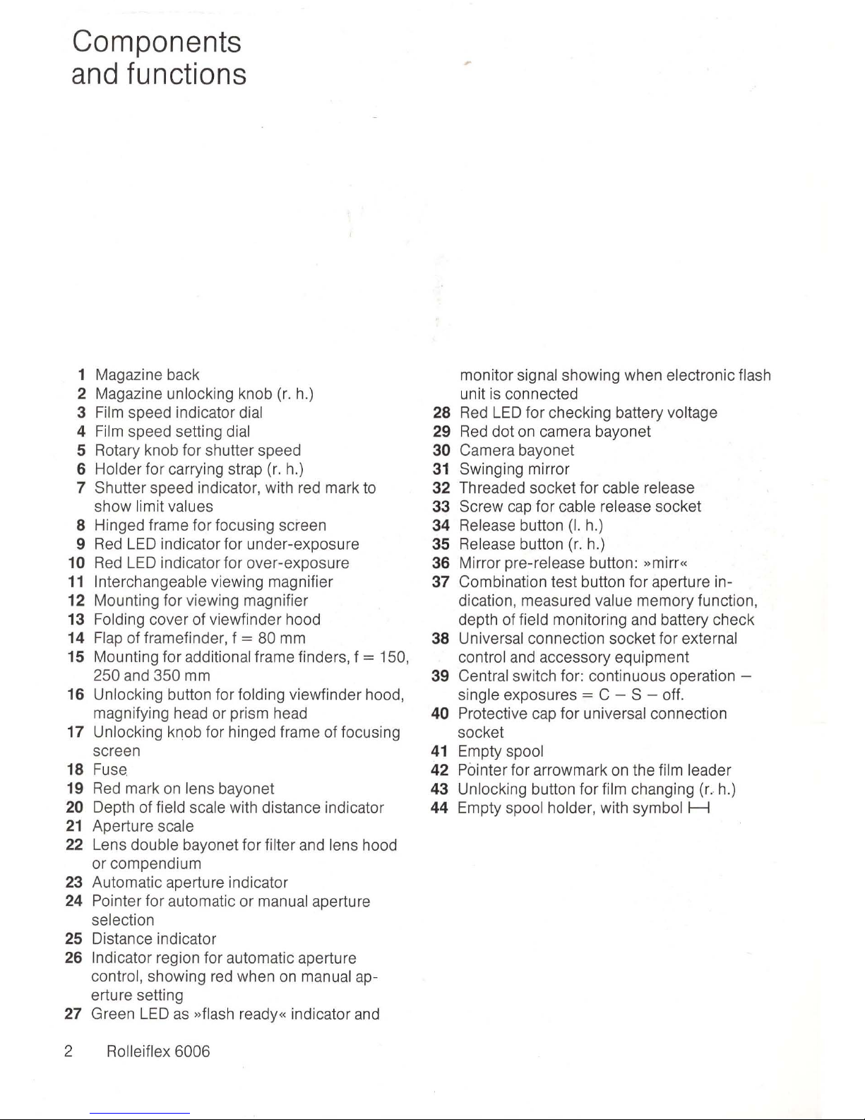
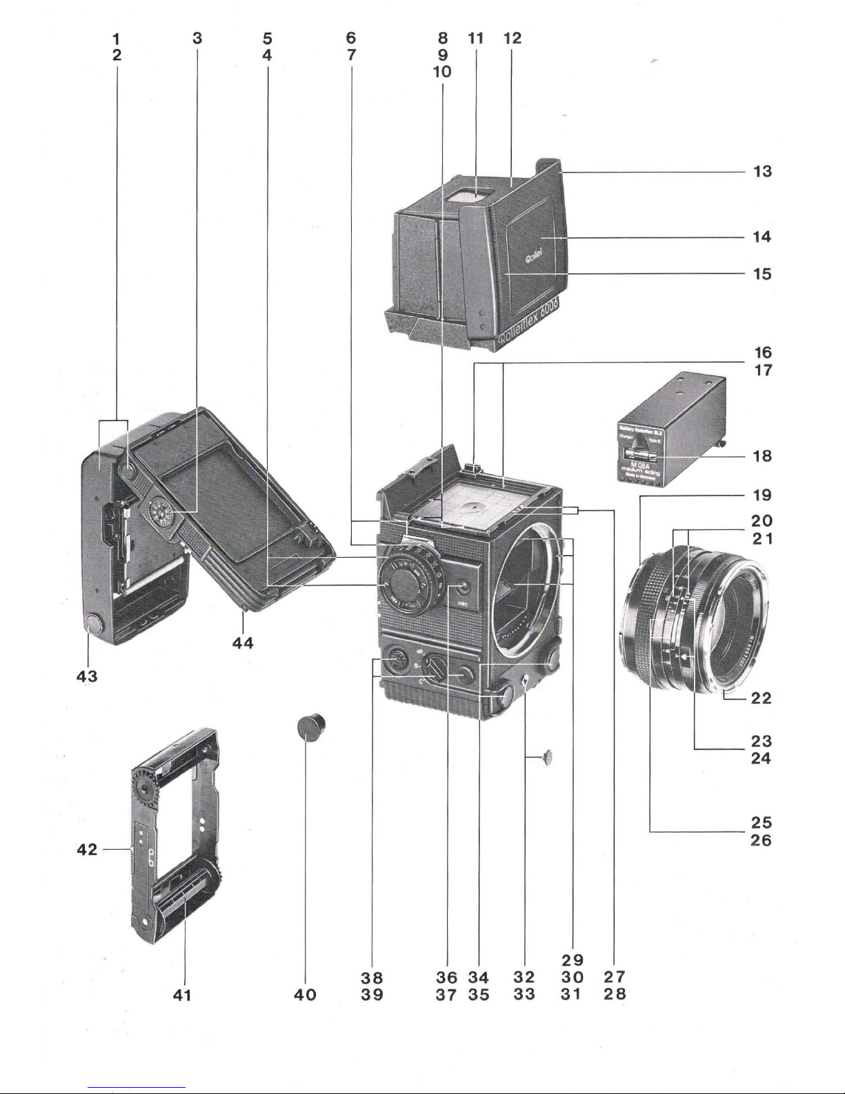
Components
and
functions
1 Magazine back
2 Magazine
unlocking knob
(r.
h.)
3
Film
speed indicator dial
4
Film
speed setting dial
5 Rotary knob for shutter speed
6 Holder for carrying strap
(r.
h.)
7 Shutter speed indicator, with red mark to
show limit values
8 Hinged frame for focusing screen
9
Red
LED
indicator for under-exposure
10
Red
LED
indicator for over-exposure
11
Interchangeable viewing magnifier
12 Mounting for viewing magnifier
13 Folding cover of viewfinder hood
14
Flap
of framefinder, f = 80 mm
15 Mounting for additional frame finders, f = 150,
250
and 350 mm
16 Unlocking button for folding viewfinder hood,
magnifying head or prism head
17 Unlocking knob for hinged frame of focusing
screen
18 Fuse
19
Red
mark
on
lens bayonet
20 Depth of field scale with distance indicator
21
Aperture scale
22 Lens double bayonet for filter and lens hood
or compendium
23 Automatic aperture indicator
24 Pointer for automatic or manual aperture
selection
25 Distance indicator
26
Indicator region for automatic aperture
control, showing
red
when
on
manual ap-
erture setting
27 Green
LED
as
»flash ready« indicator
and
2 Rolleiflex 6006
monitor signal showing when electronic flash
unit
is
connected
28
Red
LED
for checking battery voltage
29
Red
dot
on
camera bayonet
30
Camera bayonet
31
Swinging mirror
32
Threaded socket for cable release
33 Screw
cap
for cable release socket
34
Release button
(I.
h.)
35
Release button
(r.
h
.)
36
Mirror pre-release button: »mirr«
37
Combination test button for aperture indication, measured value memory function,
depth of
field monitoring and battery check
38
Universal connection socket for external
control
and
accessory equipment
39 Central switch for: continuous operation -
single exposures = C - S - off.
40
Protective cap for universal connection
socket
41
Empty spool
42
Pointer for arrowmark
on
the film leader
43
Unlocking button for film changing (r. h.)
44
Empty spool holder, with symbol H
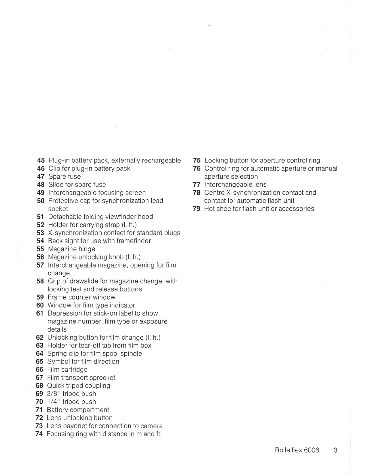
45 Plug-in battery pack, externally rechargeable
46 Clip for plug-in battery pack
47 Spare fuse
48 Slide for spare fuse
49 Interchangeable focusing screen
50 Protective cap for synchronization lead
socket
51
Detachable folding viewfinder hood
52 Holder for carrying strap
(I.
h.)
53 X-synchronization contact for standard plugs
54 Back sight for use with framefinder
55 Magazine hinge
56 Magazine unlocking knob
(I.
h.)
57 Interchangeable magazine, opening for film
change
58 Grip of drawslide for magazine change, with
locking test and release buttons
59 Frame counter window
60 Window for film type indicator
61
Depression for stick-on label to show
magazine number, film type or exposure
details
62 Unlocking button for film change
(I.
h.)
63 Holder for tear-off tab from film box
64 Spring clip for film spool spindle
65 Symbol for film direction
66
Film
cartridge
67
Film
transport sprocket
68 Quick tripod coupling
69
3/8"
tripod bush
70
1/4"
tripod bush
71
Battery compartment
72 Lens unlocking button
73 Lens bayonet for connection to camera
74 Focusing ring with distance
in
m and
ft.
75 Locking button for aperture control ring
76 Control ri
ng
for automatic aperture or manual
aperture selection
77 Interchangeable lens
78 Centre X-synchronization contact and
contact for automatic flash unit
79
Hot shoe for flash unit or accessories
Rolleiflex 6006 3
Rolleiflex
6006
Hints for use
To
make full use of the technology offered by
the camera, some
technical expertise and a
certain amount of
specialist knowledge are
required.
While the owner of the Rolleiflex 6006
may be assumed to have the expertise, these
instructions are intended
to
provide the specialist
knowledge
needed to use the camera correctly.
A comprehensive list of the components and
functions
is
followed by a short introduction for
readers
in
a hurry to get
on
with their phot-
ography.
Next,
all
the important information about the
camera is given and
illustrated
in
detail. All the
operations are described
in
order, from the
assembly of the basic components to the removal
of the exposed film.
There follows a number of practical tips, with
additional information for a better understanding
of the camera,
supplemented by notes on special
photographic situations.
The
tables contain the most important data
on
the range of interchangeable lenses.
In
case of problems
in
operating the camera
- which even the experienced photographer
may have when taking pictures
in
a hurry or after
a
long period of not using the camera - a trouble-
shooting guide will facilitate the establishment of
the
possib le cause and its solution.
4 Rolleiflex 6006
Individual
component numbers mentioned
in
the text and illustrations always refer
to
the same
components and are first given
in
the two picture
gatefo lds, which are best left unfolded when
reading the instructions.
~ollei
fototechnic
Rollei
Fototechnic GmbH
Essential
information
in
brief
Rapid information
in
telegraphic style for
readers
in
a hurry to get on with their phot-
ography: the most important
controls and opera-
tions for
familiarizing oneself with the camera
and its functions. Anyone who wishes to have a
more
detailed knowledge of the camera right
from the start
should carryon reading
on
page
10.
Rolleiflex SLX owners should note that, with
the exception of the SLX camera body and
back, all the interchangeable components
can
also be used with the Rolleiflex 6006.
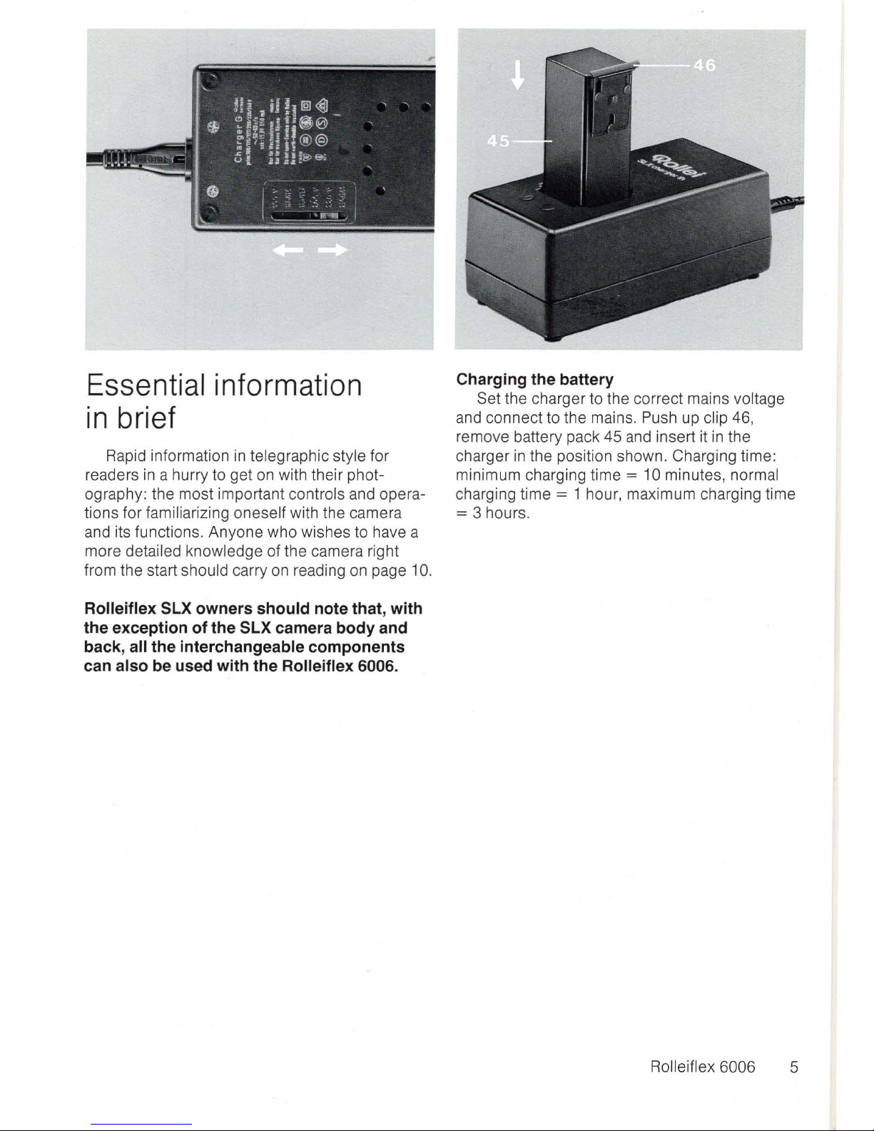
Charging the battery
Set the charger to the correct mains voltage
and connect to the mains. Push up clip 46,
remove battery pack 45 and insert it
in
the
charger
in
the position shown. Charging time:
minimum charging time
= 10 minutes, normal
charging time = 1 hour, maximum charging time
= 3 hours .
Rolleiflex 6006 5
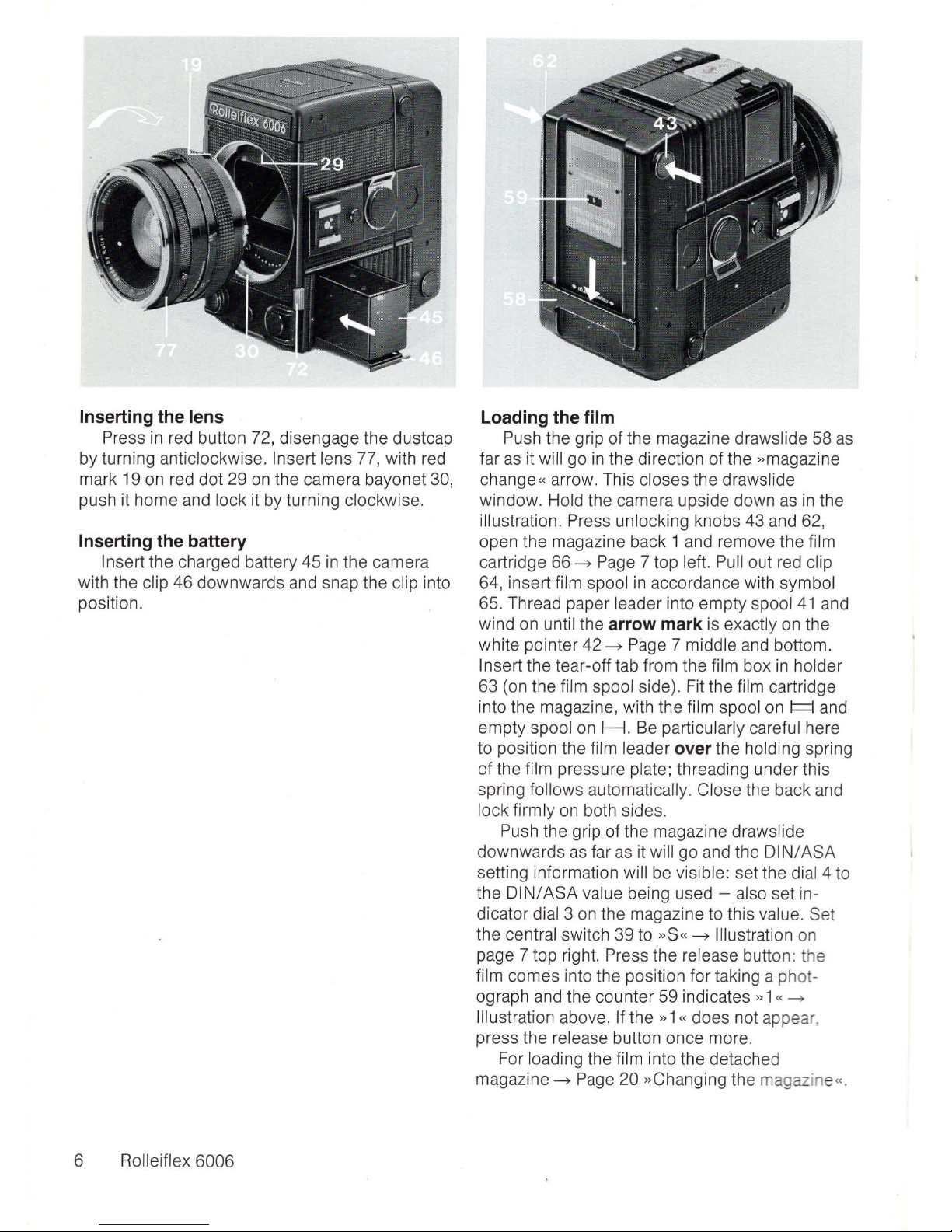
Inserting the lens
Press
in
red button 72, disengage the dustcap
by turning anticlockwise.
Insert lens 77, with red
mark 19 on red dot 29
on
the camera bayonet 30,
push it home and lock it by turning clockwise.
Inserting the battery
Insert the charged battery 45
in
the camera
with the c
li
p 46 downwards and snap the clip into
position.
6
ROlleiflex 6006
Loading the film
Push the grip of the magazine draws lide 58
as
far
as
it will
go
in
the direction of the »magazine
change«
arrow. This closes the drawslide
window . Hold the camera upside down
as
in
the
illustration.
Press unlocking knobs 43 and 62,
open the magazine back 1 and remove the film
cartr
id
ge 66
->
Page
7 top left. Pull out red cl
ip
64, insert film spool
in
accordance w
ith
symbol
65. Thread paper leader into empty spool
41
and
w
in
d on until the arrow mark is exactly on the
white pointer 42
->
Page 7 middle and bottom.
Insert the tear-off tab from the film box
in
holder
63 (on the film spool side). Fit the
fi
lm
cartridge
into the magazine, with the film spool on
I=f
a
nd
empty spool on
H.
Be particularly careful here
to position the fi
lm
leader over the holding spring
of the film pressure plate; threading under this
spring follows automatica
ll
y.
Close the back and
lock firml y on both sides.
Pu
sh the grip of the magazine drawslide
downwards
as
far
as
it will go and the
DI
NI ASA
sett
in
g information will be visible: set the dial 4
to
the
DIN/ASA
value being used - also set in-
dicator dial 3 on the magazine to this value. Set
the central switch 39 to
»S"
->
Illustration
on
page 7 top right. Press the release button: the
film comes into the position for taking a photograph and the counter 59
indicates» 1
«->
Illustration above. If the »1 « does not appear,
press the release button once more.
For loading the film into the detached
magazine
->
Page
20 »Changing the magazine
«.

Focusing
Raise the viewfinder hood 51. Press flap
14
in
slightly so that the magnifier swings upwards.
Focus by turning the focusing ring 74.
Selecting the shutter speed
Use rotary knob 5 to set the shutter speed
against marker
7.
Intermediate values cannot
be
used.
If
this marker changes from white to red ,
the
selected speed lies outside the automatic
range - choose another speed for which the
marker shows white.
Rolleiflex 6006 7
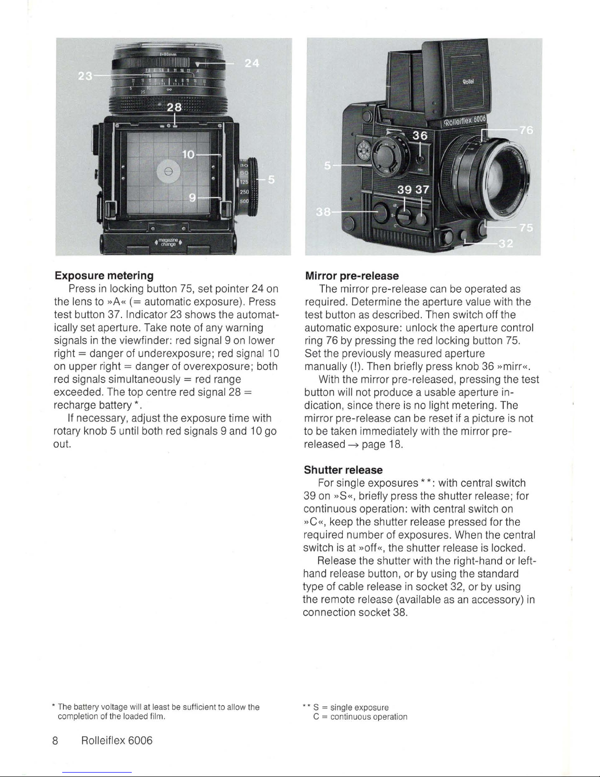
Exposure metering
Press in
lock
ing button 75,
set
pointer 24 on
the
lens to »A«
(=
automatic
exposure
). Press
test button 37. Indicator 23
shows
th e automat-
ically
set
aperture. Take not e
of
any warning
signals
in
the
viewfinder
: red signal 9 on
lower
right =
danger
of underexposure; red signal 10
on
upper right =
danger
of
overexposure
; both
red signals simultaneously
= red range
exceeded. The
top
centre red signal 28 =
recharge battery *.
If necessary, adjust the
exposure
time with
rotary knob
5 unt
il
both red signals 9 and 10 go
out.
• The battery voltage will at least be sufficient to allow the
co
mpletion of the loaded film.
8 Rolleifle x
6006
Mirror pre-release
The mirror pre-release can be operated as
required. Determine
the
aperture value with the
test button as described. Then
sw
itch off
the
automatic exposu re: unlock
the aperture control
ring 76 by pressing the red locking button 75.
Set
the
previously measured aperture
manua
ll
y (!). Then briefly press knob 36 »mirr«.
With
the
mirror pre-released, pressing the
test
button wi
ll
not
produce a usable aperture indication, since there is no light metering. The
mirror pre-release can be reset if a picture is not
to be taken immediately with
the
mirror pre-
released
.....
page 18.
Shutter release
For single exposures * *: with centr
al switch
39
on »S
«,
briefly press the
shutter
release; for
continuous
operation: with central switch on
»C
«,
keep the shutter release pressed for th e
required
number
of
exposures
. When the central
switch is at
»
off
«, the
shutter
release is locked.
Release the shutter with
the
right-hand or left-
hand release button, or by using
the
standard
type of cable release in
socket 32,
or
by using
the
remote release (available as
an
accessory)
in
connection
socket
38
.
••
S = single exposure
C = continuous operation
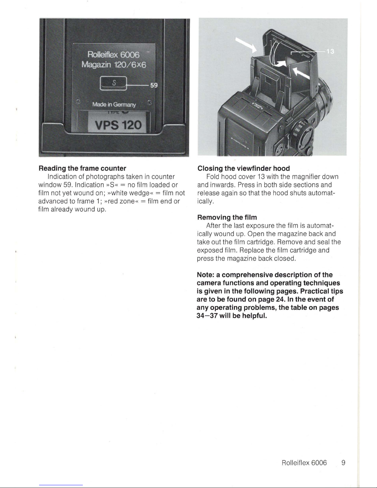
Reading the frame counter
In
dication of photographs taken
in
counter
window 59.
Indication »S« = no film loaded or
film not yet wound on; »white wedge« = film not
advanced to frame
1;
»red zone« = film e
nd
or
film already wound
up.
Closing the viewfinder hood
Fold hood cover 13 with the magnifier down
and inwards. Press
in
both side sections and
release again so that the hood shuts automatically.
Removing the film
After the last exposure the film is automat-
icall
y wound up. Open the magazine back and
take out the
film cartridge. Remove and seal the
exposed
film. Replace the film cartridge and
press the magazine back
closed.
Note: a comprehensive description of the
camera functions and operating techniques
is given in the
following pages. Practical tips
are to be found on page 24.
In
the event of
any operating problems, the table on pages
34-37
will be helpful.
Rolleiflex 6006 9
Handling
and
use
This section describes, by way of example,
the process of making single automatic exposures with the basic equipment of the camera,
from the assembly of the individual components 1)
to the removal of the exposed film. The description of the essential techniques
is
followed by
an
additional expl
anation
and further hints for an-
yone who requires them .
Customers who
already have a Rolleiflex SLX
should particularly note that almost all the
interchangeable components of the Rolleiflex
SLX
can be used on the Rolleiflex 6006. Only
the SLX camera body and back cannot and
must not be used with the Rolleiflex 6006.
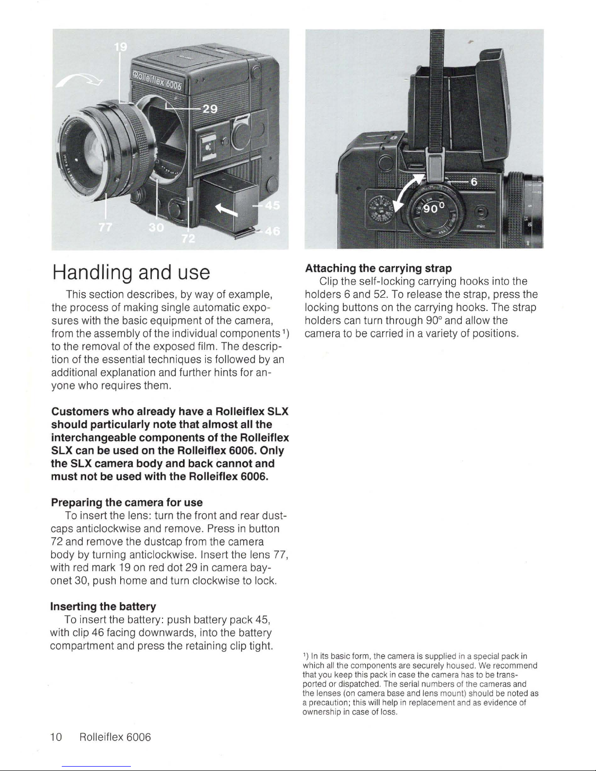
Preparing the camera for use
To
insert the lens: turn the front and rear dust-
caps
anticlockwise and remove. Press
in
button
72 and
remove the dustcap from the camera
body by turning anticlockwi
se. Insert the lens
77,
with red mark 19
on
red dot
29
in
camera bay-
onet 30, push home and turn clockwise to lock.
Inserting the battery
To insert the battery: push battery pack 45,
with clip
46 facing downwards, into the battery
compartment and press the retaining clip tight.
10 Rolleiflex 6006
Attaching the carrying strap
Clip the self-locki
ng
carrying hooks into the
holders 6 and 52. To release the strap, press the
locking buttons
on
the carrying hooks. The strap
holders
can
turn through 90°
and
allow the
camera to be carried
in
a variety of positions.
')
In its basic form, the camera is supplied
in
a special pack in
whi
ch all
the components are securely housed.
We
recommend
th
at
you keep this pack
in
case the camera has to be trans-
ported or dispatch ed. The serial numbers of the cameras and
the
lenses (on ca
mer
a base and lens mount) should be noted as
a precaution; this will help
in
replacement and as evidence of
ow
nership in case of loss.

Opening the viewfinder hood
Hinge the top section upwards until vertica
l.
Press the front flap 14 slightly inwards until cover
13 with
viewing magnifier
11
springs up.
Framefinder for
eye-level viewing: press
down
flap 14 until it snaps into position. Viewing
takes
place through the back sight
(in
this position, focusing cannot be monitored on the
focusing screen).
Checki
ng
the power supply
Switch on the automatic exposure control:
press
in
the red locking button 75 underneath the
lens and set the white pointer 24 to
"A".
Set the
central switch 39 to "S« = single exposure or
»C"
= continuo us operation. Push down the
drawslide grip 58
as
far
as
it wi
ll
go. Press test
button 37 and
look at the viewfinder image. If
diode 28 does not light
up
and
an
aperture in-
dication appears (accompani
ed
by
an
audible
signal)
at
the lens, the battery
is
adequately
charged; if diode 28 glows red, the battery is only
charged sufficiently for a few pictures and must
soon
be
recharged; if the diode remains unlit
without any aperture indication, the battery
is
totally discharged (after a long period of use or
through
self-discharge) and must be recharged
immediately. The power supp ly
can
only
be
effectively tested when a lens
is
fitted.
At each
light measurement and exposure, the
camera
electronics carries out
an
automatic
voltage check.
It
registers a criti
cal
or insufficient
battery
voltage by means of correspondi
ng
signals in the viewf inder
as
described above and
will eventually switch off the camera if the vo ltage
is
no
longer sufficient for one exposure and film
transport cycl
e.
Rolleiflex 6006 11
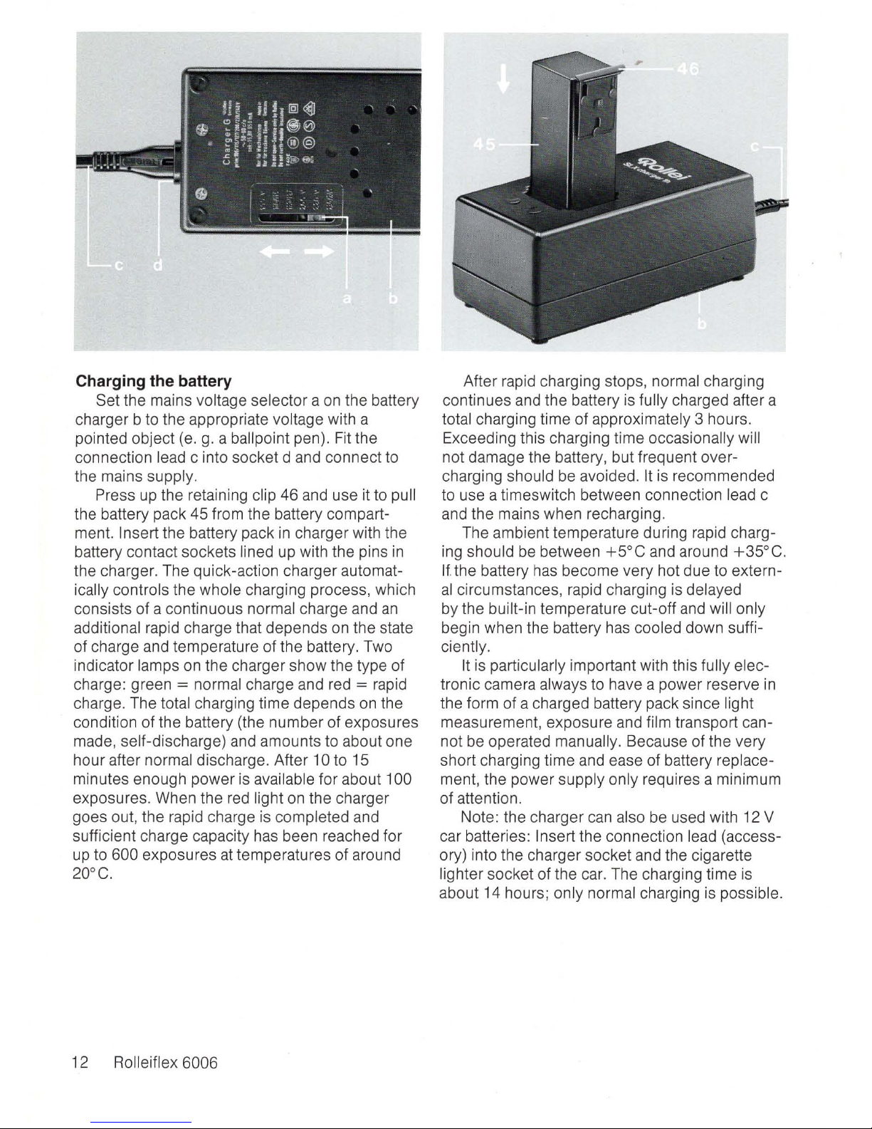
Charging the battery
Set the mains voltage selector a on the battery
charger b to the appropriate
voltage with a
pointed object
(e.
g.
a ballpoint pen). Fit the
connection
lead c into socket d and connect to
the mains
supply.
Press
up
the retaining clip 46 and use it to pull
the battery pack 45 from the battery compartment.
Insert the battery pack
in
charger with the
battery contact sockets
lined
up
with the pins
in
the charger. The quick-action charger automat-
ically controls the whole charging process, which
consists of a continuous
normal charge and
an
additional rapid charge that depends on the state
of charge and temperature of the battery. Two
indicator
lamps
on
the charger show the type of
charge: green
= normal charge and red = rapid
charge. The
total charging time depends on the
condition of the battery (the number of exposures
made, self-discharge) and amounts to about one
hour after
normal discharge. After 10 to 15
minutes enough power is
available for about 100
exposures. When the red light on the charger
goes out, the rapid charge is
completed and
sufficient charge capacity has been reached for
up
to 600 exposures
at
temperatures of around
20°
C.
12 Rolleiflex 6006
After rapid charging stops, normal charging
continues and the battery is
fully charged after a
total charging time of approximately 3 hours .
Exceeding this charging time
occasionally will
not damage the battery, but frequent over-
charging should be avoided.
It
is
recommended
to use a timeswitch between connection
lead c
and the mains when recharging.
The ambient temperature during rapid charg-
ing
should
be
between
+5°C
and around
+35°C.
If the battery
has
become very hot due to extern-
al
circumstances, rapid charging
is
delayed
by the built-in temperature cut-off and will only
begin when the battery has cooled down sufficiently.
It
is
particularly important with this fully elec-
tronic camera always to
have
a power reserve
in
the form of a charged battery pack since light
measurement, exposure and film transport cannot be operated
manually. Because of the very
short charging time and ease of battery replacement, the power supply only requires a minimum
of attention.
Note: the charger
can
also be used with
12
V
car batteries: I nsert the connection lead (accessory) into the charger socket and the cigarette
lighter socket of the car. The charging time is
about 14 hours;
only normal charging is possible.
 Loading...