

Page 1
AUTOMATE PARADIGM FLUSH WALL SWITCH
433MHz
TECHNICAL
SPECIFICATIONS
Voltage:
3V
(CR2430)
Frequency:
433.92 MHz
TransmittingPower:
10
milliwatt
Ambient Operating
Temperature:
-
10˚C -50˚C
Transmission
Distance:
up
to 200 meters (open
space)
PACK CONTENTS
• Switch
• Fixing screws& anchors
• InstructionManual
• 3V – CR2430 Battery
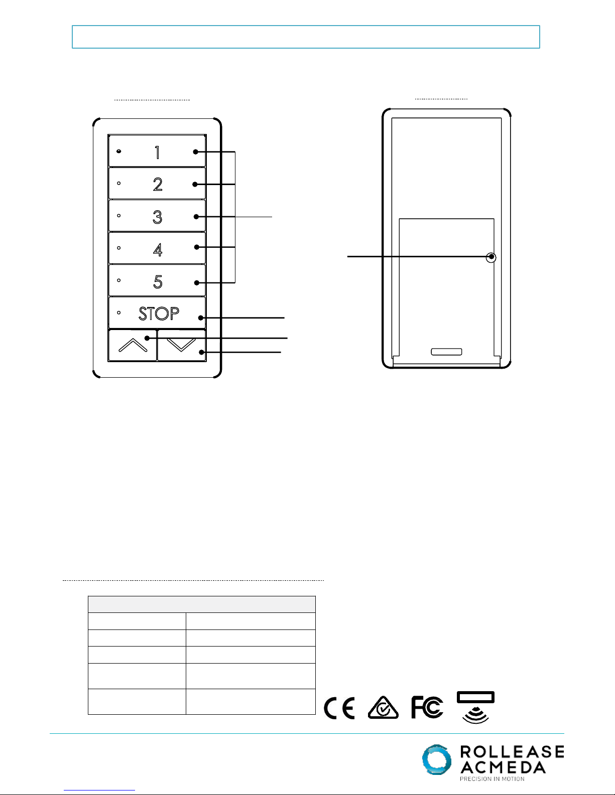
BACK
FRONT
Page. 1 of6
STOP
CHANNELS
UP
DOWN
P2 BUTTON
Page 2
CONTENTS
DISPOSAL
Do not dispose of in general waste. Please recycle batteries and damaged electrical products appropriately
CAUTION
Do not expose to moisture or extreme temperatures
Replace with correct battery type asspecified
Do not allow children to play with this device or battery.
Use or modification outside the scope of this instruction manual will void warranty.
Select channel p4
Pairing to motor
p4
p4
p5
Adding & deleting switches.
Page. 2 of 6
© 2016 RolleaseAcmeda
p5
Declaration of Conformity required for EU market
U.S. Radio Frequency FCC Compliance
This device complies with Part 15 of the FCC Rules. Operation is subject to the following two conditions:
(1) This device may not cause harmful interference, and
(2) This device must accept any interference received, including interference that may cause undesired
operation.
Mounting switch
p3
p3
p6
Group Control
Troubleshooting
Adding & deleting channels.
Installing switch batterY
Page 3

Install battery with
positive(+) side
facing up
INSTALL SWITCH BATTERY
Remove cover
from switch:
Insert a flat-tip
screw driver into
the gap between
covers located
on the bottom of
switch. Twist
driver as shown
to separate
switch halves.
1
2
Replace cover
by placing
halves together
and pressing
firmly until
snaps engage
3
Page. 3 of 6
© 2016 RolleaseAcmeda
MOUNTING SWITCH
Use supplied fasteners and anchors as needed to
attach base to desired surface as shown in figure
NEED STP FILE FOR MOUNT
TO CREATE ILLUSTRATION
HERE
Page 4

Press & hold button
on motor head (3sec)
Motor Response
JOG 1X + BEEP 1X
Within 4sec,
Press & Hold
STOP (3sec)
Motor Response
JOG 2X + BEEP 3X
2. PAIRING SWITCH TO MOTOR
Page. 4 of 6
© 2016 RolleaseAcmeda
1. SELECT CHANNEL
ACTIVATE PAIRING MODE ON MOTOR
OR
Detail View of Switch
Controls
2a(Any Motor)
2b
PowerON
motor
Motor Response
BEEP 1X
(Non-Battery
Motor)
3. GROUP CONTROL
Explanation: in this step you are going to pair multiple motors to a single
channel on your switch. This will allow you to operate a series of motors in
unison without needing to change channels.
• Ensure that each motor you want to group is also assigned to another channel by
itself
• Confirm that motor limits and favorite position are already set for each individual
motor
• Select the channel you want to control the group of motors with
• REPEAT steps 2A and 2B for all motors using your desired group channel
To select a
channel or
group of
channels:
Press
desired
channel
button(s)
until LED’s
appear
1a
To de-select
a channel:
Press
channel
button(s)
until channel
LED
disappears
1b
2a
Page 5
CHANGE TO
CHANNELTO BE
ADDED OR
DELETED
Page. 5 of 6
© 2016 RolleaseAcmeda
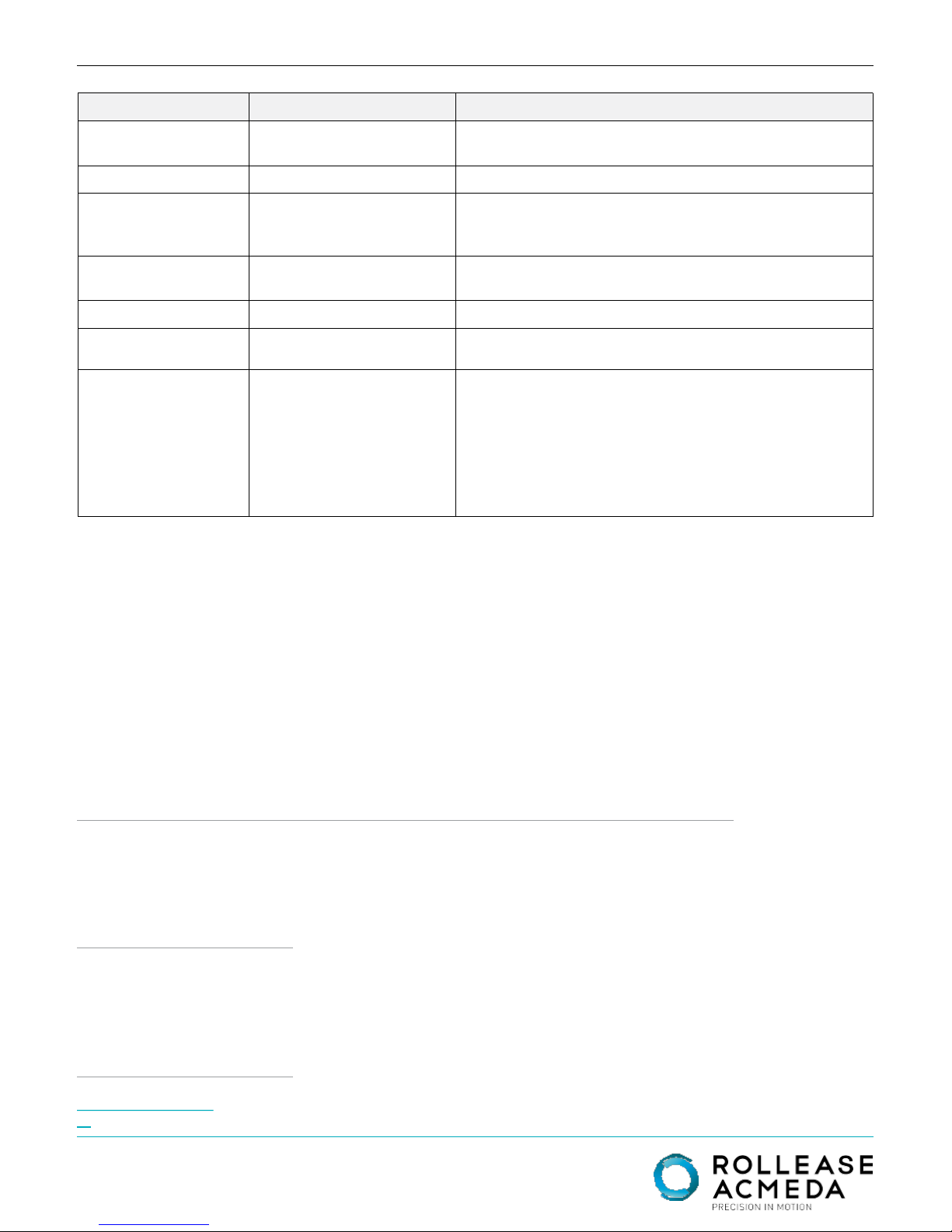
5. ADDING & DELETING CHANNELS
CHANGE TO
CONTROLLER
TO BE ADDED
OR DELETED
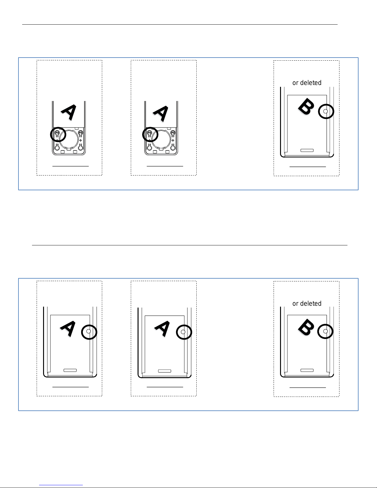
A = Existing Controller
B = Controller to be added
4. ADDING & DELETING SWITCHES
Press P2 (1sec) on
controller to be added
or deleted
Motor Response
JOG 2X + BEEP 3X
4c
Press P2 (1sec) on
existing channel
5a
5b
Motor Response
JOG 1X + BEEP 1X
Press P2 (1sec) on
existing channel
Motor Response
JOG 1X + BEEP 1X
Press P2 (1sec) on
channel to be added
or deleted
Motor Response
JOG 2X + BEEP 3X
5c
Press P2 (1sec) on
existing controller
4a
4b
Motor Response
JOG 1X + BEEP 1X
Press P2 (1sec) on
existing controller
Motor Response
JOG 1X + BEEP 1X
A = Existing Controller
B = Controller to be deleted
ADDING DELETING
A = Existing Channel
B = Channel to be added
A = Existing Channel
B = Channel to be deleted
ADDING DELETING
Page 6
ROLLEASE
ACMEDA
AUSTRALIA
110 NorthcorpBoulevard,
Broadmeadows VIC3047
T +61 3 9355 0100 | F +61 3 9355
0110
Western Australia Branch
Unit 1, 41 MulgulRoad,
Malaga WA6090
T +61 8 9248 5571 | F +61 8 9248
5572
QueenslandBranch
Unit 2/62 BorthwickAvenue,
Murarrie QLD4172
ROLLEASE
ACMEDA EUROPE
Via Conca Del Naviglio 18,
Milan (Lombardia)Italy
T +39 02 8982 7317 | F +39 02 8982
7317
info@rolleaseacmeda.co
m rolleaseacmeda.com
ROLLEASE
ACMEDA USA
200 HarvardAvenue
Stamford, CT 069026320
T +1 203 964 1573 | F +1 203 964
0513
Page. 6 of 6
TROUBLESHOOTING
PROBLEM
CAUSE
REMEDY
Motor
is not responding
Switch
battery is dis-
charged
Replace
battery
Battery
is inserted incorrectly
Check
batterypolarity
Radio interference
/ Shielding
Ensure
switch is positioned away from metal objects and that
aerial
on motor or receiver is kept straight and away from
metal
.
Receiver
distance is too far
from
switch
Move
switch to a closer position.
Power
failure
Check
power supply to motor is connected and active.
Incorrect
wiring
Check wiring is
connected correctly (refer to motor installation
instructions
)
Cannot set limits on a
single Motor (multiple
motors respond)
Using “group” channels to
adjust motor limits
Always reserve an individual channel for programming
functions.
SYSTEM BEST PRACTICE
– Provide an extra 15
channel switch in your multi motor projects, that
provides individual control for each motor for
programming purposes.
 Loading...