

Page 1
AUTOMATE
™
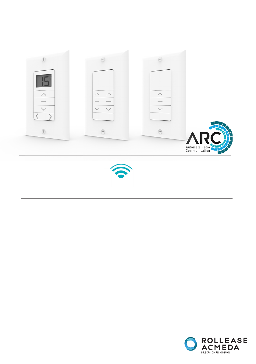
Paradigm Cut-In Wall Switches
433 MHz
AUTOMATE™ | Paradigm wall switches feature a contemporary design and a wirefree
deployment, making them retrofit ready for any location. Available in single, double or
15 channel configurations, Paradigm switches are perfect for individual room and whole
home shade control.
FEATURES:
• Available in single, double & Fifteen Channel.
• LCD display (15 Channel SWITCH).
• Compatible with screwless decorator cover plates.
• Hide unused channel function (15 Channel SWITCH).
• Retrofit Ready.
• Group Control.
INSTR-MTRF-SW-1C.2C.15LED V1.1 MAR 2017
Page 2

CONTENTS
1 TECHNICAL DATA / PACK CONTENTS 3
2 SAFETY 4
3 INSTALLATION 5
3.1 Install switch batteries 5
3.2 Mount switch 5
4 FUNCTIONAL OVERVIEW 6
4.1 Buttons 6
4.2 Selecting a channel (15 channel switch) 6
4.3 Group control using CH “0” 7
4.4 Hide unused channels (15 channel switch) 7
4.5 Lock Limit Setting (1 & 2 channel switch) 8
4.6 Lock Limit Setting (15 channel switch) 8
5 ADDING / REMOVING CONTROLLERS & CREATING GROUP CHANNELS 9
5.1 Using motor P1 button 9
5.2 Using a pre-exisiting controller 9
6 TROUBLESHOOTING 10
2 | Automate™ Programming Instructions | Paradigm Cut-In Wall Switches ROLLEASE ACMEDA
Page 3

1 TECHNICAL DATA / PACK CONTENTS
TECHNICAL SPECIFICATIONS
Voltage: 3V (2 x AAA)
Frequency: 433.92 MHz
Transmitting Power: 10 milliwatt
Ambient Operating Temperature: -10°C -50°C
Transmission Distance: up to 200 meters (open space)
PACK CONTENTS
1 x switch (Single, Double or Fifteen Channel)
2 x Wall fixing screws & anchors
1 x Instruction manual
2 x 1.5V - AAA batteries
1 x white single gang decorator style wall plate (incl. 2 mounting screws)
ROLLEASE ACMEDA Automate™ Programming Instructions | Paradigm Cut-In Wall Switches | 3
Page 4

2 SAFETY
5005833
WARNING: Important safety instructions to be read before installation and use.
Incorrect installation or use can lead to serious injury and will void manufacturer’s liability and warranty.
It is important for the safety of persons to follow the enclosed instructions. Save these instructions for future reference.
• Do not expose to water, moisture, humid and damp environments or extreme temperatures.
• Persons (including children) with reduced physical, sensory or mental capabilities, or lack of experience and knowledge
should not be allowed to use this product.
• Use or modification outside the scope of this instruction manual will void warranty.
• Installation and programming to be performed by a suitably qualified installer.
• Follow installation instructions.
• For use with motorized shading devices.
• Keep away from children.
• Frequently inspect for improper operation. Do not use if repair or adjustment is necessary.
• Keep clear when in operation.
• Replace battery with correctly specified type.
Rollease Acmeda declares this equipment is in compliance with the essential requirements and other relevant provisions of
R&TT EC Directive 1999/5/EC
Statement Regarding FCC Compliance
This device complies with Part 15 of the FCC Rules.Operation is subject to the following two conditions:
(1) This device may not cause harmful interference, and
(2) This device must accept any interference received, including interference that may cause undesired operation.
Note:
This equipment has been tested and found to comply with the limits for a Class B digital device, pursuant to Part 15 of the FCC
Rules. These limits are designed to provide reasonable protection against harmful interference in a residential installation.
This equipment generates, uses and can radiate radio frequency energy and, if not installed and used in accordance with the
instructions, may cause harmful interference to radio communications.
However, there is no guarantee that interference will not occur in a particular installation. If this equipment does cause
harmful interference to radio or television reception, which can be determined by turning the equipment off and on, the user is
encouraged to try to correct the interference by one or more of the following measures:
• Reorient or relocate the receiving antenna.
• Increase the separation between the equipment and receiver.
• Connect the equipment into an outlet on a circuit different from that to which the receiver is connected.
•Consult the dealer or an experienced radio/TV technician for help.
Any changes or modifications not expressly approved by the party responsible for compliance could void the user’s authority to
operate the equipment.
Do not dispose of in general waste.
Please recycle batteries and damaged electrical products appropriately.
4 | Automate™ Programming Instructions | Paradigm Cut-In Wall Switches ROLLEASE ACMEDA
Page 5

3 INSTALLATION
3.1 Install switch batteries
Open rear battery cover by pressing gently in,
then sliding down.
3.2 Mount switch
Use supplied fasteners and anchors as needed
Install 2 x AAA batteries with negative side
facing springs.
Replace cover by sliding into place.
to attach base.
ROLLEASE ACMEDA Automate™ Programming Instructions | Paradigm Cut-In Wall Switches | 5
Page 6

4 FUNCTIONAL OVERVIEW
4.1 Buttons
4.2 Selecting a channel (15 channel switch)
Use left and right arrows to change channels. Press right arrow button to increase channel.
Response
LCD screen will indicate selected channel.
IMPORTANT
Please refer to the relevant documentation of your motor model for instructions on adjusting motor settings.
6 | Automate™ Programming Instructions | Paradigm Cut-In Wall Switches ROLLEASE ACMEDA
Page 7

4.3 Group control using CH “0”
Channel "0" is pre-set to control ALL shades paired within your multi-channel switch. To create a
customized group channel ref to section 5.2
4.4 Hide unused channels (15 channel switch)
Your multi channel switch can be configured to have anywhere between 1 to 15 visible channels.
Inactive channels will not be visible when scrolling through the < > selections.
Press and hold left and
right arrow buttons for
three seconds.
Press right arrow button
to decrease channels.
Press the STOP button
Response Response Response
LCD screen displays “C”
then changes to “15”
ROLLEASE ACMEDA Automate™ Programming Instructions | Paradigm Cut-In Wall Switches | 7
LCD screen displays the
selected number of channels.
LCD screen displays”o” to
indicate the channel number
has been set.
Page 8

4.5 Lock Limit Setting (1 & 2 channel switch)
The upper and lower limit setting can be locked by holding the STOP button for 15 seconds.
Holding the STOP button for a further 15 seconds will unlock these settings.
Press STOP and hold
for 15 seconds.
Release STOP
button.
Locked limit
settings.
Remote response Remote response
All lights flash x1 All lights flash x2
Press STOP and hold
for 15 seconds.
Release STOP
button.
Unlocked limit
settings.
4.6 Lock Limit Setting (15 channel switch)
The 15 channel remote uses the LCD screen to notify the user when the lock feature has been activated.
Press STOP and hold
for 15 seconds.
Press STOP and hold
for 15 seconds.
Release STOP
button.
Unlocked limit
settings.
Remote response Remote response
LCD flash “U” x2 LCD flash “L” x2
8 | Automate™ Programming Instructions | Paradigm Cut-In Wall Switches ROLLEASE ACMEDA
Release STOP
button.
Locked limit
settings.
Page 9

5 ADDING / REMOVING CONTROLLERS & CREATING GROUP CHANNELS
IMPORTANT
Multiple motors can be grouped onto shared channels for co-ordinated control. Limit settings and favorite positions cannot be adjusted when
motors are grouped together.
* Confirm that motor limits and favorite position are already set for each individual motor.
* Ensure that each motor you want to group is also assigned to another channel by itself
5.1 Using motor P1 button
Select channel on Switch.
Using the side arrow
buttons.
Hold P1 button on motor
Hold STOP on Switch.
head.
Motor Response Motor Response
RELEASE P1
5.2 Using a pre-exisiting controller
Press P2 on existing
switch.
Motor Response Motor Response Motor Response
ROLLEASE ACMEDA Automate™ Programming Instructions | Paradigm Cut-In Wall Switches | 9
Press P2 on existing
switch.
Press P2 on new switch or
remote controller.
Page 10

6 TROUBLESHOOTING
Problem Cause Remedy
Switch battery is discharged Replace battery
Battery is inserted incorrectly Check battery polarity
Ensure switch is positioned away
Radio interference / Shielding
from metal objects and that antenna
on motor or reciever is kept straight
and away from metal.
Motor is not responding
Receiver distance is too far
from remote
Power failure
Incorrect wiring
Cannot set limits on a single
motor (multiple motors
respond)
NOTE
The switch can be used to set/adjust limits.
Please refer to the motor instructions for limit setting functions.
Using “Group” channels to
adjust motor limits
Move switch to a closer position
Check power supply to motor is
connected and active
Check wiring is connected correctly
(refer to motor installation
instructions)
Always reserve an individual channel
for programming functions.
SYSTEM BEST PRACTICE - Provide
an extra 15 channel switch in your
multi motor projects, that provides
individual control for each motor for
programming purposes.
10 | Automate™ Programming Instructions | Paradigm Cut-In Wall Switches ROLLEASE ACMEDA
Page 11

NOTES
ROLLEASE ACMEDA Automate™ Programming Instructions | Paradigm Cut-In Wall Switches | 11
Page 12

ROLLEASE ACMEDA
AUSTRALIA
110 Northcorp Boulevard,
Broadmeadows VIC 3047
T +61 3 9355 0100 | F +61 3 9355 0110
ROLLEASE ACMEDA
USA
200 Harvard Avenue
Stamford, CT 06902 6320
T +1 203 964 1573 | F +1 203 964 0513
ROLLEASE ACMEDA
EUROPE
Via Conca Del Naviglio 18, Milan
(Lombardia) Italy
T +39 02 8982 7317 | F +39 02 8982 7317
info@rolleaseacmeda.com
rolleaseacmeda.com
Queensland Branch
Unit 2/62 Borthwick Avenue,
Murarrie QLD 4172
12 | Automate™ Programming Instructions | Paradigm Cut-In Wall Switches
 Loading...