

Page 1
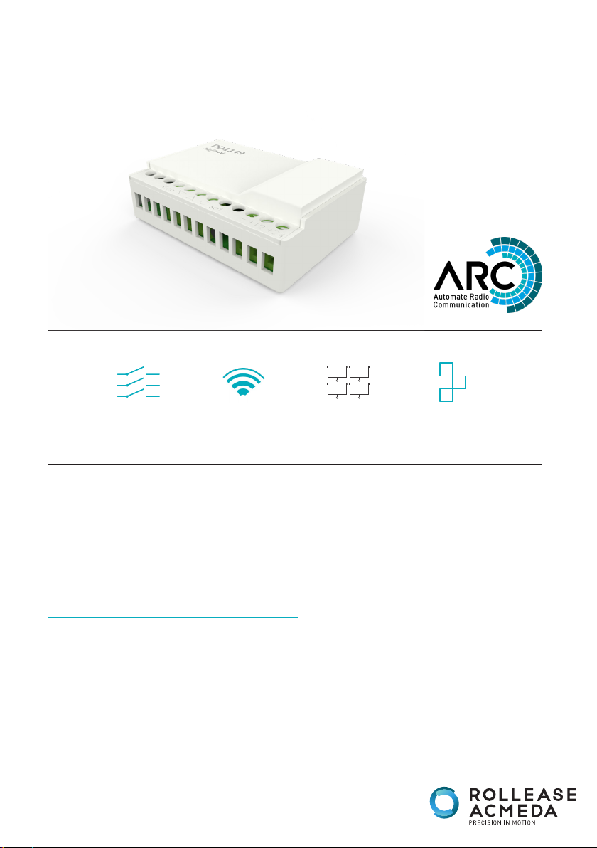
Dry Contact Input Transmitter
DRY CONTACT
INPUT
4.33 MHz SEQUENCE
GROUP
CONTROL
1
2
1
MODE
AUTOMATE | Dry contact input transmitter enables most common mechanical switches
or automation systems relays to control ARC motorized shades. It functions as a single
channel transmitter and accepts dry contact input. Once a motor or group of motors
are paired to the transmitter, it converts the dry contact inputs and sends ARC radio
commands to trigger those motors to move upward/downward.
FEATURES:
• Interface between third party smart home systems and ARC motors
• Three dry contact inputs
• Wireless signal output
• ARC motor communication protocol
• Group Motor Control
• Four switch modes
• 12V or 24V power source compatible
MTRF-DCIM-1C_v1.0_JULY_2018
Page 2

CONTENTS
1 TECHNICAL DATA / PACK CONTENTS 3
2 SAFETY 4
3 INSTALLATION 5
3.1 Overview 5
3.2 Wire Diagram 5
4 SETTING SWITCH MODE 6
5 ADDING OR DELETING A TRANSMITTER & CREATING A GROUP OF CHANNELS 7
5.1 Using motor P1 button 7
5.2 Using a pre-existing controller 7
6 SWITCH MODE OPERATION 8
6.1 Operation of Normal Switch Mode 8
6.2 Operation of Pulse Switch Mode 9
6.3 Operation of Mechanical Switch Mode 10
6.4 Operation of Sequence Switch Mode 11
6.5 Operation of Favorite Position 12
7 TROUBLESHOOTING 13
NOTES 14
2 | Automate™ Programming Instructions | MTRF-DCIM-1C ROLLEASE ACMEDA
Page 3
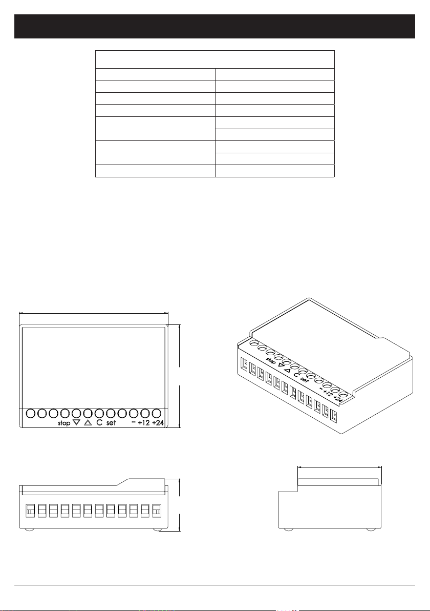
1 TECHNICAL DATA / PACK CONTENTS
1 STATIC TITLE
TECHNICAL SPECIFICATIONS
12V Power Input Voltage: 8V ~ 16V
24V Power Input Voltage: 16V ~ 26V
Radio Frequency 433.92 MHz
Transmitting Power: 10 milliwatt
Ambient Operating
Temperature:
Transmission Distance:
Dry Contract Input Duration >0.25 seconds
PACK CONTENTS
1x contact closure box
1 x instructions
-10°C ~ 50°C
14°F ~ 122°F
up to 200m (open space)
up to 656’ (open space)
DIMENSIONS
[2 1/2"]
65mm
[1 3/4"]
45mm
[7/8"]
23mm
[1 1/2"]
37mm
3 | Automate™ Programming Instructions | MTRF-DCIM-1C ROLLEASE ACMEDA
Page 4

2 SAFETY
5005833
WARNING: Important safety instructions to be read before installation.
Incorrect installation can lead to serious injury and will void manufacturer’s liability and warranty.
It is important for the safety of persons to follow the enclosed instructions.
Save these instructions for future reference.
CAUTION
• Do not expose to moisture or extreme temperatures.
• Persons (including children) with reduced physical, sensory or mental capabilities, or lack of experience and knowledge
should not be allowed to use this product.
• Use or modification outside the scope of this instruction manual will void warranty.
• Installation and programming to be performed by a suitably qualified installer.
• Follow installation instructions.
• For use with motorized shading devices.
• Keep away from children.
• Frequently inspect for improper operation. Do not use if repair or adjustment is necessary.
• Keep clear when in operation.
Rollease Acmeda declares this equipment is in compliance with the essential requirements and other relevant provisions of
R&TT EC Directive 1999/5/EC.
Statement Regarding FCC Compliance
This device complies with Part 15 of the FCC Rules. Operation is subject to the following two conditions:
(1) This device may not cause harmful interference, and
(2) This device must accept any interference received, including interference that may cause undesired operation.
Note:
This equipment has been tested and found to comply with the limits for a Class B digital device, pursuant to Part 15 of the FCC
Rules. These limits are designed to provide reasonable protection against harmful interference in a residential installation.
This equipment generates, uses and can radiate radio frequency energy and, if not installed and used in accordance with the
instructions, may cause harmful interference to radio communications.
However, there is no guarantee that interference will not occur in a particular installation. If this equipment does cause
harmful interference to radio or television reception, which can be determined by turning th equipment off an on, the user is
encouraged to try correct the interference by one or more of the following measures:
• Reorient or relocate the receiving antenna
• Increase the separation between the equipment and receiver
• Connect the equipment into an outlet on a circuit different from that to which the receiver is connected
• Consult the dealer or an experienced radio/TV technician for help
Any changes or modifications not expressly approved by the party responsible for compliance could void the user’s authority to
operate the equipment.
Do not dispose of in general waste.
Please recycle batteries and damaged electrical products appropriately.
4 | Automate™ Programming Instructions | MTRF-DCIM-1C ROLLEASE ACMEDA
Page 5
[2 1/2"]
65mm
[1 3/4"]
45mm
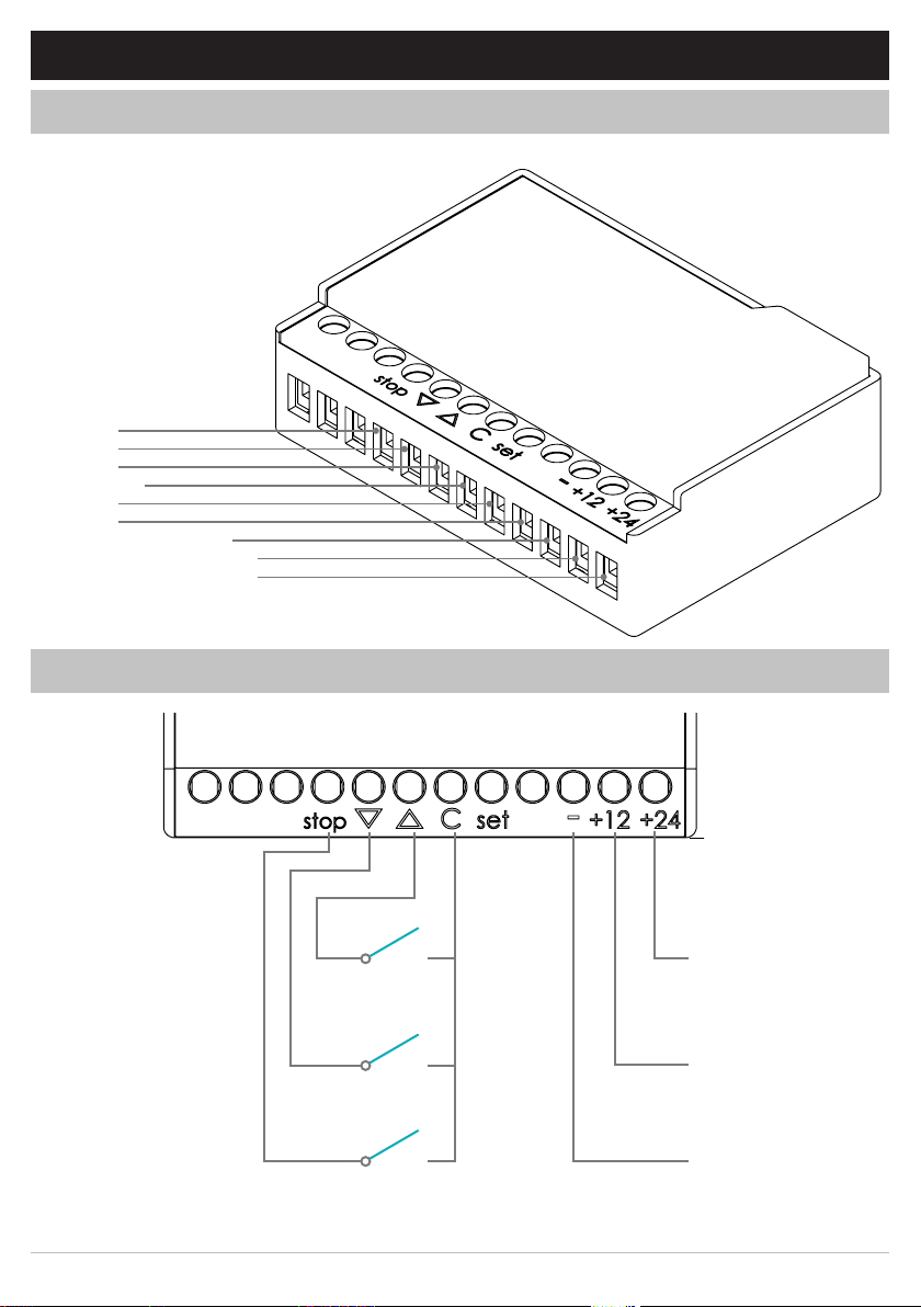
3 FUNCTIONAL OVERVIEW
3.1 Overview
STOP
DOWN
UP
COMMON
SET
LED
GROUND CONTACT
POSITIVE CONTACT 12V
POSITIVE CONTACT 24V
3.2 Wiring Diagram
+24V
+12V
GROUND
NOTE: Only one positive power point, +12V or +24V, is needed.
ROLLEASE ACMEDA Automate™ Programming Instructions | MTRF-DCIM-1C | 5
Page 6

4 SETTING SWITCH MODE
[2 1/2"]
65mm
[1 3/4"]
45mm
IMPORTANT
The SET button is utilized to choose the working mode of the dry contact input transmitter as described below:
Continuously hold SET button
and release when the desirable
switch mode is achieved.
NORMAL SWITCH MODE
Approx.
LED Response
FLASH x2
LED Response
FLASH x1
PULSE SWITCH MODE
Approx.
LED Response
FLASH x2
LED Response
FLASH x1
MECHANICAL SWITCH MODE
Approx.
LED Response
LED Response
RELEASE SET BUTTON
Approx.
RELEASE SET BUTTON
LED Response
FLASH x1
Approx.
LED Response
Approx.
LED Response
LED flashing indicates switch
mode type.
RELEASE SET BUTTON
FLASH x2
SEQUENCE SWITCH MODE
FLASH x1
Approx.
FLASH x1
Approx.
FLASH x1
Approx. Approx.
RELEASE SET BUTTON
LED Response
FLASH x2
6 | Automate™ Programming Instructions | MTRF-DCIM-1C ROLLEASE ACMEDA
LED Response
FLASH x1
LED Response
FLASH x1
LED Response LED Response
FLASH x1 FLASH x1
Page 7

5 ADDING OR DELETING TRANSMITTER & CREATING GROUP CHANNELS
[2 1/2"]
65mm
[1 3/4"]
45mm
[2 1/2"]
65mm
[1 3/4"]
45mm
IMPORTANT
Multiple motors can be paired to the dry contact input transmitter for group control. Their limit settings and
favorite positions should be individually adjusted by a single channel remote, which is only paired to one of
those motors
• Confirm that motor limits and favorite position are already set for each individual motor.
• Ensure that each motor you want to group is also assigned to a channel by itself or another remote.
5.1 Using Motor P1 Button
NOTE: This is not applicable in mechanical switching mode.
Hold P1 button on motor head.
Motor Response
RELEASE P1
5.2 Using a preexisting Controller
Press P2 on existing controller.
Pres P2 on existing controller.
Hold STOP on controller to add
or remove.
Motor Response
Approx.
Press and release SET button on
new transmitter.
Motor Response Motor Response Motor Response
ROLLEASE ACMEDA Automate™ Programming Instructions | MTRF-DCIM-1C | 7
Page 8

6 SWITCH MODE OPERATION
Prior to selecting a switch mode, the upper and bottom limits of any ARC motors must be set.
A single or combination of three dry contact inputs can operate the paired ARC motors.
6.1 Operation of Normal Switch Mode
NOTE: In this mode, the transmitter can implement all the ARC remote functions. The P2 button of the
remote is described as the SET button in the transmitter. Please refer to the motor instructions for
functions such as setting/adjusting limits, setting a favorite position, toggling tilt/roller mode etc.
MOVE UP UNDER ROLLER MOTOR MODE
STOP
DOWN
UP
CLOSED
OPEN
CLOSED
OPEN
CLOSED
OPEN
UPPER LIMIT
COMMON
LOWER LIMIT
MOVE DOWN UNDER ROLLER MOTOR MODE
STOP
DOWN
UP
CLOSED
OPEN
CLOSED
OPEN
CLOSED
OPEN
UPPER LIMIT
COMMON
LOWER LIMIT
STOP UNDER ROLLER MOTOR MODE
STOP
DOWN
UP
CLOSED
OPEN
CLOSED
OPEN
CLOSED
OPEN
UPPER LIMIT
COMMON
LOWER LIMIT
8 | Automate™ Programming Instructions | MTRF-DCIM-1C ROLLEASE ACMEDA
Page 9

6.2 Operation of Pulse Switch Mode
NOTE: The time interval of each pulse should be in the range of 0.25 ~ 2.0 seconds. The motor rotation can
be stopped by using the STOP button or the UP & DOWN together in the roller motor mode. In the tilt mode,
each closing pulse triggers the motor to move one small step but a pulse longer than 2 seconds can trigger
continuous movement of the motor.
MOVE UP/DOWN, STOP IN ROLLER MOTOR MODE
STOP
DOWN
UP
CLOSED
OPEN
CLOSED
OPEN
CLOSED
OPEN
UPPER LIMIT
COMMON
LOWER LIMIT
MOVE UP IN TILT MOTOR MODE
STOP
DOWN
UP
CLOSED
OPEN
CLOSED
OPEN
CLOSED
OPEN
UPPER LIMIT
COMMON
LOWER LIMIT
MOVE DOWN IN TILT MOTOR MODE
STOP
DOWN
UP
CLOSED
OPEN
CLOSED
OPEN
CLOSED
OPEN
UPPER LIMIT
COMMON
LOWER LIMIT
ROLLEASE ACMEDA Automate™ Programming Instructions | MTRF-DCIM-1C | 9
Page 10

6.3 Operation of Mechanical Switch Mode
NOTE: Closing the UP/DOWN dry contacts keeps the motor rotating, opening the dry contacts immediately
stops the rotation in the roller motor mode. In the tilt motor mode, each UP/DOWN closing pulse, whatever
the pulse duration, triggers the motor to move one UP/DOWN step.
MOVE UP IN THE ROLLER MOTOR MODE
STOP
DOWN
UP
CLOSED
OPEN
CLOSED
OPEN
CLOSED
OPEN
UPPER LIMIT
COMMON
LOWER LIMIT
MOVE DOWN IN THE ROLLER MOTOR MODE
STOP
DOWN
UP
CLOSED
OPEN
CLOSED
OPEN
CLOSED
OPEN
UPPER LIMIT
COMMON
LOWER LIMIT
OPERATION IN TILT MOTOR MODE
STOP
DOWN
UP
CLOSED
OPEN
CLOSED
OPEN
CLOSED
OPEN
UPPER LIMIT
COMMON
LOWER LIMIT
10 | Automate™ Programming Instructions | MTRF-DCIM-1C ROLLEASE ACMEDA
Page 11

6.4 Operation of Sequence Switch Mode
NOTE: The closing/releasing of the “UP” pin alternatively triggers the upward movement or the stopping
of the paired motor. The closing of the “DOWN” pin alternatively triggers the downward movement or the
stopping of the paired motor.
MOVE UP IN THE ROLLER MOTOR MODE
STOP
DOWN
UP
CLOSED
OPEN
CLOSED
OPEN
CLOSED
OPEN
UPPER LIMIT
COMMON
LOWER LIMIT
MOVE DOWN IN THE ROLLER MOTOR MODE
STOP
DOWN
UP
CLOSED
OPEN
CLOSED
OPEN
CLOSED
OPEN
UPPER LIMIT
COMMON
LOWER LIMIT
ROLLEASE ACMEDA Automate™ Programming Instructions | MTRF-DCIM-1C | 11
Page 12

6.5 Operation of Favorite Position
NOTE: Closing the STOP pin for more than 5 seconds can activate the motor to move to the preset favorite
position under Normal, Pulse & Sequence Mode.
FAVORITE POSITION
STOP
DOWN
UP
CLOSED
OPEN
CLOSED
OPEN
CLOSED
OPEN
UPPER LIMIT
COMMON
FAVORITE
LOWER LIMIT
12 | Automate™ Programming Instructions | MTRF-DCIM-1C ROLLEASE ACMEDA
Page 13

7 TROUBLE SHOOTING
Problem Cause Remedy
Motor is not responding
Cannot set limits on a single
motor (multiple motors respond)
Motor will not go down after
setting the top limit
Switch power supply is not
connected
Radio interference / Shielding
Receiver distance is too far from
switch
Power failure
Incorrect motor wiring
Transmitter has group control
function set and drives all the
paired motors together
Top limit was set using the down
and stop buttons
Check power source and
connections.
Ensure switch is positioned away
from metal objects and that
the antenna on motors are kept
straight and away from metal.
Move switch to a closer position.
Check power supply to motor is
connected and active (non-battery
motors).
Check motor wiring is connected
correctly (refer to motor
installation instructions).
Use an ARC remote to individually
adjust motor limits.
Use P1 motor button to set other
motors in group into “Sleep” mode.
SYSTEM BEST PRACTICE - Provide
an extra 15 channel switch or
remote in you multi motor projects
to provide individual control for
each motor for programming/
configuration purposes.
Reset the motor and begin
programming sequence again.
Remember that upper limit is to be
set using the up and stop and the
down limit is set using the down
and stop.
ROLLEASE ACMEDA Automate™ Programming Instructions | MTRF-DCIM-1C | 13
Page 14

NOTES
14 | Automate™ Programming Instructions | MTRF-DCIM-1C ROLLEASE ACMEDA
Page 15

NOTES
15 | Automate™ Programming Instructions | MTRF-DCIM-1C ROLLEASE ACMEDA
Page 16

ROLLEASE ACMEDA | AUSTRALIA
110 Northcorp Boulevard,
Broadmeadows VIC 3047
T +61 3 9355 0100 | F +61 3 9355 0110
ROLLEASE ACMEDA | USA
750 East Main Street
7th Floor, Stamford, CT 06902 6320
T +1 203 964 1573 | F +1 203 964 0513
ROLLEASE ACMEDA | EUROPE
Via Conca Del Naviglio 18, Milan
(Lombardia) Italy
T +39 02 8982 7317 | F +39 02 8982 7317
info@rolleaseacmeda.com
rolleaseacmeda.com
16 | Automate™ Programming Instructions | MTRF-DCIM-1C
 Loading...