

rollease acmeda AUTOMATE MT01-1145-069011, AUTOMATE MT01, AUTOMATE Programming Instructions Manual
Page 1
AUTOMATE
™
X50 VERTICAL DROP AWNING MOTOR
433 MHZ
BI-DIRECTIONAL
ELECTRONIC
LIMIT
FAVORITE
POSITION
AUTOMATE | X50 Vertical Drop Awning Motor combine the simple, intuitive features of
ARC “Automate Radio Communication” with the higher lifting capacity of an AC motor for
larger shade applications.
INSTR. MT01-1145-069011 v1.1 OCT 2018
Page 2

2 | Automate™ Programming Instructions | ARC VDA Motor ROLLEASE ACMEDA
CONTENTS
1 ASSEMBLY 4
2 WIRING 5
3 P1 BUTTON FUNCTIONS 6
3.1 Motor state test 6
3.2 Motor configuration options 6
4 INITIAL SET UP 7
4.1 Pair motor with controller 7
4.2 Check motor direction 7
4.3 Set Limits 8
5 ADJUSTING LIMITS 9
5.1 Adjust upper limit 9
5.2 Adjust lower limit 9
6 ADDING OR REMOVING CONTROLLERS AND CHANNELS 10
6.1 Using motor P1 Button to add a new controller or channel 10
6.2 Using a pre-existing controller to add or remove a controller or channel 10
7 FAVORITE POSITIONING 11
7.1 Set a favorite position 11
7.2 Send shade to favorite position 11
7.3 Delete favorite position 11
8 SLEEP MODE 12
9 WIND SENSOR FUNCTION 13
9.1 Wind Sensor Prioritize Function 13
9.2 Off line Wind Sensor Function 13
11 TROUBLE SHOOTING 14
Page 3
3 | Automate™ Programming Instructions | ARC VDA Motor ROLLEASE ACMEDA
SAFETY INSTRUCTIONS
WARNING: Important safety instructions to be read before installation.
Incorrect installation can lead to serious injury and will void manufacturer’s liability and warranty.
CAUTION
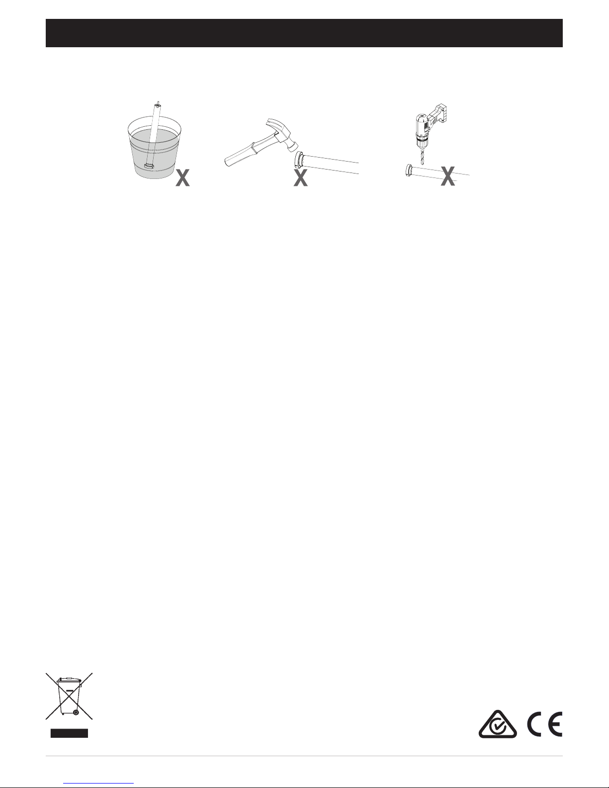
• Do not expose to moisture or extreme temperatures.
• Do not allow children to play with this device.
• Use or modification outside the scope of this instruction manual will void warranty.
• Installation and programming to be performed by a suitably qualified installer.
• For use within tubular blinds.
• Ensure correct crown and drive adaptors are used for the intended system.
• Keep antenna straight and clear from metal objects
• Do not cut the antenna.
• Use only Rollease Acmeda hardware.
• Before installation, remove any unnecessary cords and disable any equipment not needed for powered operation.
• Ensure torque and operating time is compatible with end application.
• Do not expose the motor to water or install in humid or damp environments.
• Motor is to be installed in horizontal application only.
• Do not drill into motor body.
• The routing of cable through walls shall be protected by isolating bushes or grommets.
• Ensure power cable and aerial is clear and protected from moving parts.
• If cable or power connector is damaged do not use.
Important safety instructions to be read prior to operation.
• It is important for the safety of persons to follow the enclosed instructions. Save these instructions for future reference.
• Persons (including children) with reduced physical, sensory or mental capabilities, or lack of experience and knowledge
should not be allowed to use this product.
• Keep remote controls away from children.
• Frequently inspect for improper operation. Do not use if repair or adjustment is necessary.
• Keep motor away from acid and alkali.
• Do not force the motor drive.
• Keep clear when in operation.
Do not dispose of in general waste.
Please recycle batteries and damaged electrical products appropriately.
Page 4
4 | Automate™ Programming Instructions | ARC VDA Motor ROLLEASE ACMEDA
.
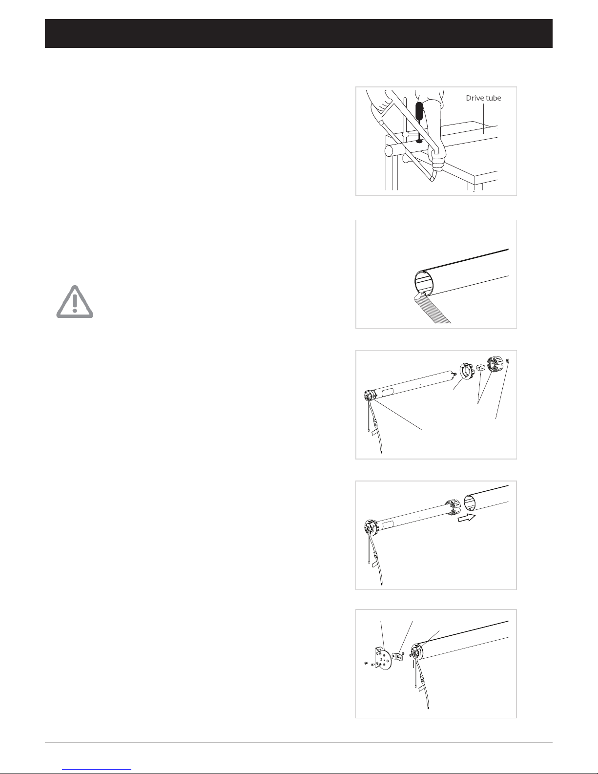
Crown
Magnetic
Ring
Bracket
Drive
Adapter
Retaining
Clip
Motor
Head
Step 1. Cut roller tube to required length.
Please refer to Rollease Acmeda System Assembly Manual for full assembly instructions relevant to the
hardware system being used.
Step 2. Ensure roller tube is clean and free from burrs.
Step 3. Fit required crown, drive and bracket adapters.
Step 4. Slide Motor into tube.
Insert by aligning key-way in crown and drive
wheel into the tube.
Step 5. Mount motorized tube onto brackets.
Refer to Rollease Acmeda System Assembly
Manual for recommended crown, drive and
bracket adapter kits.
1 ASSEMBLY
For impact dectection to be functional, a 2
piece drive set must be used. Using a standard
1 piece drive will render the collision control
feature inoperable even if the feature is turned
on.
Tube must be close fitting with chosen crown
and drive adapters. A Hall effect sensor
embedded in the tube measures the magnetic
field change and detect the impact. Refer to
Rollease Acmeda System Assembly Manual
for recommended crown, drive and bracket
adapter kits.
Page 5
5 | Automate™ Programming Instructions | ARC VDA Motor ROLLEASE ACMEDA
1
2
3
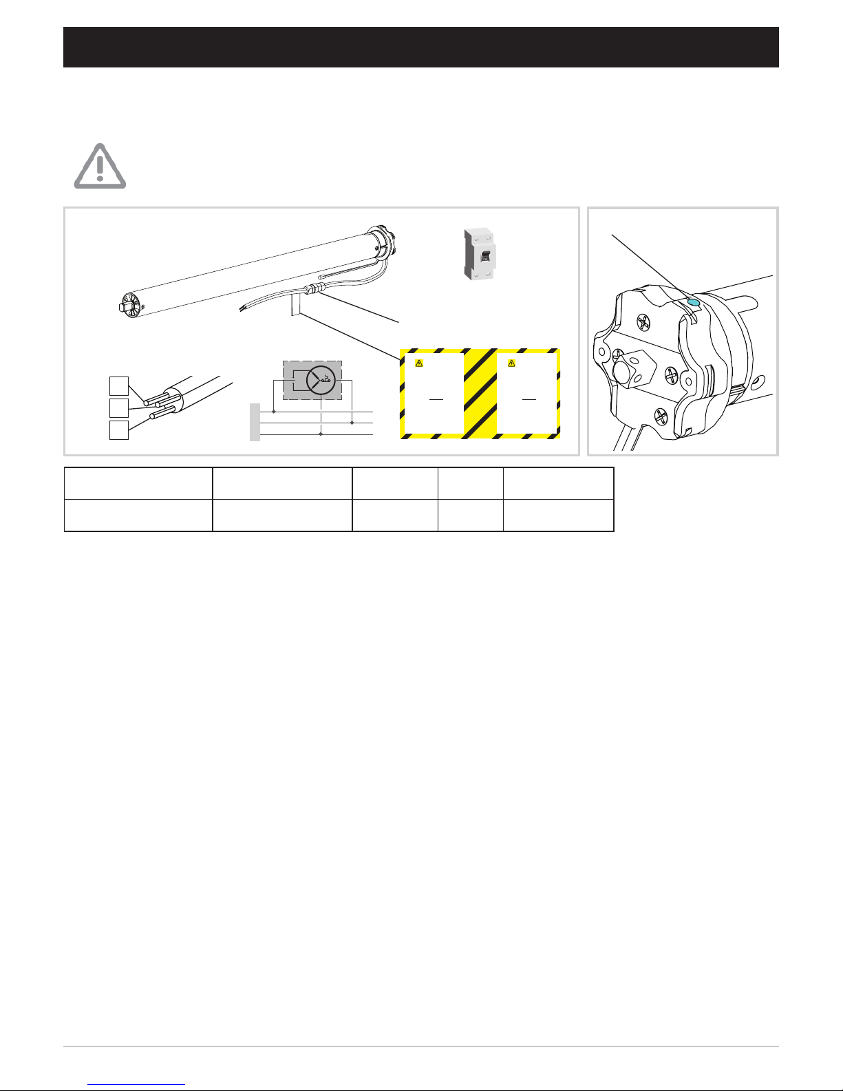
Disconnect the mains power supply.
Connect the motor according to the information in the table below.
Ensure cable is kept clear of fabric.
Ensure antenna is kept straight and away from metal objects.
Power OFF
Water proof connector
2 WIRING
MOTOR POWER NEUTRAL LIVE EARTH
MT01-1145-069011 220-240V AC 50Hz Blue Brown Yellow/Green
DO NO T RE MO VE THIS LABEL
WARNING
E L E C TRIC AL H AZARD !
Power shall only be supplied to this
cable once male & female
connectors are correctly coupled.
Isolate power prior to connecting or
disconnecting this motor.
This connector must not be accessible to the end user. It shall be
placed within a pelmet box or within
a housing in accordance to
AS/NZS 60335.1:2011 or
(BS) EN 60335-1:2012
Failure to do so could compromise
personal safety.
DO NOT REMO VE THI S LABEL
WARNING
ELE C TRIC A L H AZARD !
Power shall only be supplied to this
cable once male & female
connectors are correctly coupled.
Isolate power prior to connecting or
disconnecting this motor.
This connector must not be accessible to the end user. It shall be
placed within a pelmet box or within
a housing in accordance to
AS/NZS 60335.1:2011 or
(BS) EN 60335-1:2012
Failure to do so could compromise
personal safety.
P1 button on motor head
3
2
1
Page 6

6 | Automate™ Programming Instructions | ARC VDA Motor ROLLEASE ACMEDA
3.1 Motor state test
3.2 Motor configuration options
This table describes the function of a short P1 Button press/release (<2 seconds) depending on current motor
configuration.
The P1 Button is utilized to administer motor configurations as described below.
Approx.
Motor Response
Activate Pairing Mode
Approx.
Motor Response
Sleep Mode
Motor Response
Reverse Direction
Approx.
Motor Response
Reset To Factory Settings
Approx.
3 P1 BUTTON FUNCTIONS
P1
Press
Condition
Function
Achieved
Visual
Feedback
Audible
Feedback
Function Described
Short
Press
If limit is NOT set None No Action None No Action
If limits are set
Operational
control of motor,
run to limit. Stop
if running
Motor Runs None
Operational control
of motor after pairing
and limit setting is
completed first time
If motor is in
“Sleep Mode” &
limits are set
Wake and control
Motor wakes
and runs in a
direction
None
Motor is restored from
Sleep Mode and RF
control is active
Hold P1 button on
motor head.
Factory settings include E-type mode and disable impact detection.
10
Page 7

7 | Automate™ Programming Instructions | ARC VDA Motor ROLLEASE ACMEDA
.
4.1 Pair motor with controller
4.2 Check motor direction
Consult user manual for your
controller for information on
selecting channel.
Damage to shade may occur when operating motor prior to
setting limits. Attention should be given.
Reversing motor direction using this method is only possible
during initial set-up
Hold P1 button on
motor head.
To check travel direction of shade, press UP or
DOWN on controller.
Quick Press = Step
Long Press = Continuous Travel
To reverse shade direction, hold both UP and
DOWN.
Until the motor responds.
Select channel on
controller.
Hold STOP on
controller.
Approx.
Approx.
Motor Response
Motor Response
Motor Response
Motor is now in step mode and ready for setting limits
IMPORTANT
IMPORTANT
IMPORTANT
4 INITIAL SET UP
Page 8

8 | Automate™ Programming Instructions | ARC VDA Motor ROLLEASE ACMEDA
SECS
5
4.3 Set Limits
Cycle shade up and down prior to setting limits to settle fabric
After setting limits, motor will automatically exit from initial
set-up mode.
Move shade to the desired highest or lowest
position by pressing the UP or DOWN buttons
on controller.
To save upper limit, hold UP and STOP.
To save lower limit, hold DOWN and STOP.
Motor Response
IMPORTANT
Initial set-up is not complete
IMPORTANT
Approx.
Page 9

9 | Automate™ Programming Instructions | ARC VDA Motor ROLLEASE ACMEDA
SEC
SECSS
5
5
5.1 Adjust upper limit
5.2 Adjust lower limit
Hold UP and STOP on
controller.
Hold DOWN and STOP
on controller.
Move shade to the desired
lowest position by pressing
the DOWN button.
Move shade to the desired
highest position by pressing
the UP button.
To save upper limit, hold UP
and STOP.
To save lower limit, hold
DOWN and STOP.
Approx.
Approx.
Motor Response
Motor Response Motor Response
Motor Response
5 ADJUSTING LIMITS
SEC SECS S
5 5
Approx. Approx.
Page 10

10 | Automate™ Programming Instructions | ARC VDA Motor ROLLEASE ACMEDA
6.1 Using motor P1 Button to add a new controller or channel
6.2 Using a pre-existing controller to add or remove a controller or channel
A = Existing controller or channel (to keep)
B = Controller or channel to add or remove
Press P2
on existing
controller.
Press P2 on
existing controller.
Press P2 on another
controller / channel to
add or remove
Hold P1 button on motor
head.
Hold STOP on controller to
add. Motor keeps original
limits.
Approx.
Approx.
Motor Response
Motor Response Motor Response Motor Response
Motor Response
6 ADDING OR REMOVING CONTROLLERS AND CHANNELS
Consult user manual for your
controller or sensor
IMPORTANT
Page 11

11 | Automate™ Programming Instructions | ARC VDA Motor ROLLEASE ACMEDA
7.1 Set a favorite position
7.2 Send shade to favorite position
7.3 Delete favorite position
Press P2 on controller. Press STOP on controller. Press STOP on controller.
Move shade to the desired position by pressing the UP or DOWN button on the controller.
Press P2 on controller. Press STOP on controller. Press STOP on controller.
Approx.
Motor Response
Motor Response
Motor Response
Motor Response
Motor Response
Motor Response
7 FAVORITE POSITIONING
Page 12

12 | Automate™ Programming Instructions | ARC VDA Motor ROLLEASE ACMEDA
9 SLEEP MODE
Enter Sleep Mode
Sleep mode is utilized to
prevent a motor from incorrect
configuration during other
motor setup.
Hold P1 button on the motor
head
If multiple motors are grouped on a single channel, Sleep Mode may be used to put all but 1 motor to sleep,
allowing programming of just the one motor that remains “Awake”.
Exit Sleep Mode: Method 1
Exit sleep mode once the shade
is ready.
Press and release P1 button on
the motor head
Exit Sleep Mode: Method 2
Remove power and then
re-power the motor.
Motor Response
Motor Response
8 SLEEP MODE
Approx.
Page 13

13 | Automate™ Programming Instructions | ARC VDA Motor ROLLEASE ACMEDA
Once the motor receives a command from the wind sensor the motor will respond accordingly. At this point
the motor will ignore any other remote or sensor commands for 8 minutes. This function is needed to
avoiding contradicting multiple triggers. Keep this in mind when testing the motor with the remote after the
winds sensor has been triggered.
After the limits has been set and paired to a sensor. The motor will perform a self-check function with the
sensor every 30 minutes.
This is used to check if the wind sensor is within range or has sufficient battery power to function (on line). If
the motor does not receive a positive confirmation signal from the sensor (after 30 minutes). The motor will
move to the upper limit (safe position).
If the sensor remains off-line and the motor is overdriven with a remote, the motor will move in a step or
jolting mode to highlight that there is something wrong (sensor off-line) .
This function can be disabled and enabled as follows:
To Disable
9.1 Wind Sensor Prioritize Function
9.2 Off line Wind Sensor Function
Press UP+STOP+DOWN on controller.
Motor Response
To Re-Enable
SECS
5
Approx.
Press UP+STOP+DOWN on controller.
Motor Response
SEC S
5
Approx.
9 WIND SENSOR FUNCTION
Page 14

14 | Automate™ Programming Instructions | ARC VDA Motor ROLLEASE ACMEDA
ROLLEASE ACMEDA | AUSTRALIA
110 Northcorp Boulevard,
Broadmeadows VIC 3047
T +61 3 9355 0100 | F +61 3 9355 0110
ROLLEASE ACMEDA | USA
200 Harvard Avenue
Stamford, CT 06902 6320
T +1 203 964 1573 | F +1 203 964 0513
ROLLEASE ACMEDA | EUROPE
Via Conca Del Naviglio 18, Milan
(Lombardia) Italy
T +39 02 8982 7317 | F +39 02 8982 7317
info@rolleaseacmeda.com
rolleaseacmeda.com
G
11 TROUBLE SHOOTING
Problem
Cause
Remedy
Motor is not responding
A/C power supply not plugged in.
Check motor to power cable
connection and AC plug
Transmitter battery is discharged
Replace battery
Radio interference/shielding
Ensure transmitter is positioned
away from metal objects and the
aerial on motor or receiver is kept
straight and away from metal
Receiver distance is to far from
transmitter
Move transmitter to a closer
position
Power failure
Check power supply to motor is
connected and active
Incorrect wiring
Check that wiring is connected
correctly (refer to motor
installation instructions)
Multiple motors are paired to the
same channel
Always reserve an individual
channel for programming functions
SYSTEM BEST PRACTICE - Provide
an extra 15 channel controller in
your multi-motor projects, that
provides individual control for each
motor for programming purposes
Place all other motors into sleep
mode (refer to P1 button function
overview - Section 3)
Cannot program a single Motor
(multiple motors respond)
 Loading...