

AUTOMATE
™
| VT 1.0
ARC™ VENETIAN BLIND TILT MOTOR
433 MHZ
BI-DIRECTIONAL
ELECTRONIC
LIMIT
FAVORITE
POSITION
LEVELLING
CONTROL
SELECTABLE
AUTOMATE™ | ARC™ Venetian blind motor enables motorized tilting function of most 2”
venetian blinds. Precisely control the openness of blind vanes or simply recall a favorite
position.
FEATURES:
• Electronic Limits
• 433 MHz Bi-Directional RF Communication
• Favorite Position
• 3 x Selectable Rpm
• Jog or latch & Run Modes
INSTR. MTDCRF-TILT-1 V1.0 APRIL 2017
RPM

NOTES
2 | Automate™ Programming Instructions | ARC™ Venetian Tilt Motor ROLLEASE ACMEDA

CONTENTS
1 ASSEMBLY 5
2 WIRING 6
2.1 Power Options 6
3 P1 BUTTON FUNCTIONS 7
3.1 Motor State Test 7
3.2 Motor Configuration Options 7
4 INTIAL SETUP 8
4.1 Pair Motor with controller 8
4.2 Check motor direction 8
4.3 Set limits 9
5 ADJUSTING LIMITS 10
5.1 Adjust upper limit 10
5.2 Adjust lower limit 10
6 ADDING OR REMOVING CONTROLLERS AND CHANNELS 11
6.1 Using motor P1 button 11
6.2 Using a pre-existing controller 11
7 FAVORITE POSITIONING 12
7.1 Set favorite position 12
7.2 Send shade to favorite position 12
7.3 Delete favorite position 12
8 SLEEP MODE 13
8.1 Enter sleep mode 13
8.2 Exit sleep mode 13
9 TROUBLESHOOTING 14
3 | Automate™ Programming Instructions | ARC™ Venetian Tilt Motor ROLLEASE ACMEDA
SAFTEY INSTRUCTIONS
5005833
WARNING: Important safety instructions to be read before installation.
Incorrect installation can lead to serious injury and will void manufacturer’s liability and warranty.
CAUTION
• Do not expose to moisture or extreme temperatures.
• Do not allow children to play with this device.
• Use or modification outside the scope of this instruction manual will void warranty.
• Installation and programming to be performed by a suitably qualified installer.
• For use within tubular blinds.
• Ensure correct crown and drive adaptors are used for the intended system.
• Keep antenna straight and clear from metal objects
• Do not cut the antenna.
• Use only Rollease Acmeda hardware.
• Before installation, remove any unnecessary cords and disable any equipment not needed for powered operation.
• Ensure torque and operating time is compatible with end application.
• Do not expose the motor to water or install in humid or damp environments.
• Motor is to be installed in horizontal application only.
• Do not drill into motor body.
• The routing of cable through walls shall be protected by isolating bushes or grommets.
• Ensure power cable and aerial is clear and protected from moving parts.
• If cable or power connector is damaged do not use.
Important safety instructions to be read prior to operation.
• It is important for the safety of persons to follow the enclosed instructions. Save these instructions for future reference.
• Persons (including children) with reduced physical, sensory or mental capabilities, or lack of experience and knowledge
should not be allowed to use this product.
• Keep remote controls away from children.
• Frequently inspect for improper operation. Do not use if repair or adjustment is necessary.
• Keep motor away from acid and alkali.
• Do not force the motor drive.
• Keep clear when in operation.
Do not dispose of in general waste.
Please recycle batteries and damaged electrical products appropriately.
4 | Automate™ Programming Instructions | ARC™ Venetian Tilt Motor ROLLEASE ACMEDA
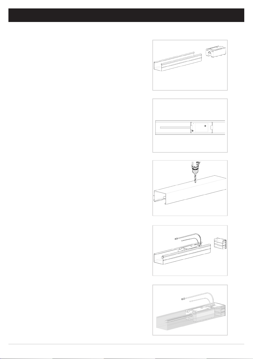
1 ASSEMBLY
The Automate Venetian Blind tily motor works with most 2” blind headrail systems.
Step 1. Insert the motor / cradle assembly completely into
the drive side of the 2” headrail
Step 2. Ensure at least ½” inch of the tilting drive
Shaft is inserted into the motor.
(max depth is ¾” – Optional Shaft adapters
may be required)
Step 3. Remove motor, mark and drill hole where P1
button can be accessed.
Step 4. Reinstall motor, ensuring power cord and
Antenna extend freely from the headrail cap.
5 | Automate™ Programming Instructions | ARC™ Venetian Tilt Motor ROLLEASE ACMEDA

2 WIRING
2.1 Power Options
Automate DC motors are powered from a 12V DC power source. AA Battery wands, re-chargeable battery
packs and A/C power supplies are available, with a variety of quick connect extension cords. For centralized
installations, power supply range can be extended with 18/2 wire (not available through Rollease Acmeda).
• During operation, if voltage drops to less than 10V, the motor will beep 10 times to indicate a power
supply issue.
• Motor will stop running when the voltage is lower than 7V and it will resume again when the voltage is
greater than 7.5V.
DC Power Supply
Power Supply Motor
MTDCRF18-0.2 - 18mm DCRF Motor, .2N/80
MTBWAND18-25 Battery Tube for 18/25mm DCRF (no Battery) Mtrs
(inc Mt clips)
MTDCPS-18-25 Power Supply for 18/25-CL/Tilt DCRF (no Bttry) Mtr
MTBPCKR-28 Rechargeable Wand
MTDCRF25-1.1 25mm DCRF Motor, 1.1N/40r
MTDCRF-TILT-1
MTDCRF-CL-0.6-50
MTDCRF18-0.2 - 18mm DCRF Motor, .2N/80
MTDCRF25-1.1 25mm DCRF Motor, 1.1N/40r
MTDCRF-TILT-1
MTDCRF-CL-0.6-50
MTDCRF18-0.2
MTDCRF25-1.1
MTDCRFQ28-2
MTDCRF-TILT-1
MTDCRF-CL-0.6-50
Extension Cables Length
MTDC-CBLXT6 DC Battery Motor Cable extender 6” / 155mm 6 inch
MTDC-CBLXT48 DC Battery Motor Cable extender 48” / 1220mm 48 inches
MTDC-CBLXT96 DC Battery Motor Cable extender 96” / 2440mm 96 inches
Ensure cable is kept clear of fabric.
Ensure antenna is kept straight and away from metal objects.
6 | Automate™ Programming Instructions | ARC™ Venetian Tilt Motor ROLLEASE ACMEDA

3 P1 BUTTON FUNCTIONS
3.1 Motor State Test
This table describes the function of a short P1 button press/release(<2 seconds) depending on current motor
configuration.
P1
Press
Condition Function Achieved
Visual
Feedback
Audible
Feedback
Function Described
If limit is NOT set None No Action None No Action
Short
Press
then
Release
(<2 sec)
If limits are set
If motor is in
“Sleep Mode” &
limits are set
(Refer to Sec.10)
Operational control
of motor, run to
limit. Stop if running
Wake and control
Motor runs None
Motor
wakes and
runs in a
None
direction
Operational control
of motor after pairing
and limit setting is
completed first time
Motor is restored from
Sleep mode and RF
control is active
3.2 Motor Configuration Options
The P1 Button is utilized to administer motor configuration as described below and beginning in Section 4.
Activate Pairing
Mode
Approx.
Motor Response
Hold P1
RELEASE P1
Sleep Mode
Approx.
P1
Motor Response
RELEASE P1
7 | Automate™ Programming Instructions | ARC™ Venetian Tilt Motor ROLLEASE ACMEDA
Reverse
Direction
Approx.
Motor Response
RELEASE P1
Reset To Factory
Settings
Approx.
Motor Response

4 INTIAL SETUP
4.1 Pair Motor with controller
Select channel on
controller.
(Disregard if using single channel
controller)
Hold P1 button on motor Hold STOP on controller
IMPORTANT
Consult user manual for your
controller for information on
selecting channel.
Motor Response Motor Response
Motor is now in setup mode and ready for setting limits.
4.2 Check motor direction
To check travel direction of shade, press UP or
DOWN on controller.
RELEASE P1
To reverse shade direction, hold both UP
and DOWN until motor responds
Motor Reponse
Reversing motor direction using this method is
only possible during initial set-up, prior to first time limit
setting, or after a re-set of motor
8 | Automate™ Programming Instructions | ARC™ Venetian Tilt Motor ROLLEASE ACMEDA

4.3 Set limits
IMPORTANT
Damage to shade may occur when operating motor prior to setting limits. Attention should be given.
To save upper limit, hold UP and STOP.
Move shade to the desired highest or lowest
position by pressing the UP or DOWN buttons
on controller.
To save lower limit, hold DOWN and STOP.
Quick Press = Step
Long Press = Continuous Travel
Motor Response
Approx.
SECS
5
Initial set-up is now complete
9 | Automate™ Programming Instructions | ARC™ Venetian Tilt Motor ROLLEASE ACMEDA

5 ADJUSTING LIMITS
5.1 Adjust upper limit
Hold UP and STOP on Controller
until the motor responds.
Move shade to the
desired upper position
To save upper limit, hold UP and STOP until
the motor responds.
by pressing the UP or
DOWN button.
Motor Response Motor Response
Approx.
SECS
5
5.2 Adjust lower limit
Hold DOWN and STOP on
controller.
Move shade to the desired lowest
position by pressing the UP or DOWN
button
To save lower limit, hold DOWN and
STOP.
Motor Response Motor Response
Approx.
10 | Automate™ Programming Instructions | ARC™ Venetian Tilt Motor ROLLEASE ACMEDA
SECS
5

6 ADDING OR REMOVING CONTROLLERS AND CHANNELS
6.1 Using motor P1 button
Hold P1 button on motor head. Hold STOP on controller to add or remove
Motor Response Motor Response
RELEASE P1
Approx.
6.2 Using a pre-existing controller
A= Existing controller or channel (to keep)
B= Controller or channel or add or remove
Press P2 on existing
controller.
Motor Response Motor Response Motor Response
Press P2 on existing
controller.
Press P2 on new
controller.
IMPORTANT
Consult user manual for your
controller or sensor.
11 | Automate™ Programming Instructions | ARC™ Venetian Tilt Motor ROLLEASE ACMEDA

7 FAVORITE POSITIONING
7.1 Set favorite position
Move shade to the desired position by pressing the UP or DOWN button on the controller.
Press P2 on controller. Press STOP on controller. Press STOP on controller.
Motor Response Motor Response Motor Response
7.2 Send shade to favorite position
Hold STOP on controller.
Approx.
7.3 Delete favorite position
Press P2 on controller. Press STOP on controller. Press STOP on controller.
Motor Response Motor Response Motor Response
12 | Automate™ Programming Instructions | ARC™ Venetian Tilt Motor ROLLEASE ACMEDA

8 SLEEP MODE
8.1 Enter sleep mode
Sleep mode is utilized to prevent a motor from moving during shipping of a fabricated shade.
Hold P1 button on motor head.
Motor Response
Approx.
Motor Response
RELEASE P1
8.2 Exit sleep mode
Exit sleep mode once shade is installed.
PRESS & RELEASE P1 button on motor head.
Motor Response
Approx.
Motor Response
MOTOR RUNS TO LIMIT
13 | Automate™ Programming Instructions | ARC™ Venetian Tilt Motor ROLLEASE ACMEDA

9 TROUBLESHOOTING
Problem Cause Remedy
A / C power supply not plugged in.
Battery in wand are depleted Replace 8xAA alkaline batteries.
Power failure
Transmitter battery is discharged Replace battery
Battery is inserted incorrectly
Motor is not responding
Unable to adjust or set limits. Remote is in a locked state.
Cannot program a single Motor
(multiple motors respond)
into transmitter
Radio interference/shielding
Receiver distance is too far from
transmitter
Incorrect wiring
Multiple motors are paired to the
same channel.
Check motor to power cable
connection and AC plug.
Check power supply to motor is
connected and active
Check battery polarity
Ensure transmitter is positioned
away from metal objects and the
aerial on motor or receiver is kept
straight and away from metal
Move transmitter to a closer
position
Check that wiring is connected
correctly (refer to motor
installation instructions)
Change remote status to an
unlocked state
Always reserve an individual
channel for programming
functions
SYSTEM BEST PRACTICE - Provide
an extra 15 channel remote in your
multi motor projects, that provides
individual control for each motor
for programming purposes
Place all other motors into sleep
mode (ref to P1 function overview
- section 3.2 and 10.1)
14 | Automate™ Programming Instructions | ARC™ Venetian Tilt Motor ROLLEASE ACMEDA

ROLLEASE ACMEDA
AUSTRALIA
110 Northcorp Boulevard,
Broadmeadows VIC 3047
T +61 3 9355 0100 | F +61 3 9355 0110
ROLLEASE ACMEDA
USA
200 Harvard Avenue
Stamford, CT 06902 6320
T +1 203 964 1573 | F +1 203 964 0513
ROLLEASE ACMEDA
EUROPE
Via Conca Del Naviglio 18, Milan
(Lombardia) Italy
T +39 02 8982 7317 | F +39 02 8982 7317
info@rolleaseacmeda.com
rolleaseacmeda.com
Queensland Branch
Unit 2/62 Borthwick Avenue,
Murarrie QLD 4172
15 | Automate™ Programming Instructions | ARC™ Venetian Tilt Motor
 Loading...