


Original instruction : French NT0002 V –h –
03/2012
1
Dear Customer,
You have just purchased a ROLLAND Spreader.
We appreciate the trust you place in us.
The Spreaders by ROLLAND were designed to make the most of
spreading techniques. They result from our technology and our
experience in this field.
This manual should be considered as part of your Rolltwin or
Rollmax Spreader.
For proper use, and to exploit all the capabilities of your Spreader,
we recommend that you carefully read and follow all instructions in
this manual.
The proper function and longevity of your spreader depends on
it as well as your safety and that of others.
Keep this instruction manual so that you can consult it in due
course. It must always accompany the spreader, even in case of
resale.
Non-compliance with the said instructions indemnifies the
manufacturer and the dealer of all liability.
We reserve the right to make any changes to our products at
any time we deem useful without obligation to modify products
previously delivered or on order. We also reserve the right to change
without notice models that are defined in our catalogues, brochures
or on our website.
Yours faithfully.
Z.A des Landes
29800 TREFLEVENEZ - FRANCE
Tél. : 00 33 (0)2 98 85 13 40
Fax : 00 33 (0)2 98 21 38 15
www.remorquerolland.com

Original instruction : French NT0002 V –h –
03/2012
2
Summary
1-Safety instructions 3
2-Conditions of warranty 4
3-Presentation of the vehicle 5
-Areas of use
-Vehicle identification
-Technology and options
4-Commissioning (PDI) 16
5-Normal use and instructions 25
-parking
-loading
-transport
-spreading
6-Settings 28
-Drawbar
7-Care and maintenance 29
-Braking systems
-undercarriage
-Cleaning/lubrication
-Adjusting the bed tension
-Adjusting the steering axle
-Maintenance of controller and hydraulic unit
- Wearing parts
-Maintenance of the beater frames
-Wheels and tyres
-Lighting
8-Assembly 42
-Revolving light flashing beacons
-Equipment
9-Annexes 48
-Hydraulic drawbar
-Passive suspension
-Hydropneumatic suspension (active suspension)
10-Maintenance logbook 58
11-Declaration of Conformity 60
12-Certificate of warranty –Declaration of commissioning 61

Original instruction : French NT0002 V –h –
03/2012
3
1-Safety instructions
Before commissioning, study the instructions and follow the safety guidelines!
In this user guide we have marked with this symbol all hazards or
risks that operators are subject or exposed to.
Signs and security stickers attached to the spreader show you that it is
safe to use the machine: Respecting the instructions = safety
A. Normal use
The spreader is designed and manufactured for normal use as described in this
manual.
Four situations are thereby defined as: parking, loading, transporting and spreading
(Chapter 5).
All uses other than specified are considered non-compliant. However, a number of
predictable non-conform situations are discussed and specifically prohibited. The
manufacturer is not liable for resulting damages.
We must respect the rules of accident prevention and other legal safety
regulations, occupational medicine and the Highway Code.
The manufacturer accepts no liability for damage resulting from an unauthorised
modification of the machine.
B. General safety regulations and accident prevention.
a. Vehicle shutdown: Before
working on the machine, stop the
engine, release the hydraulic
pressure engage the brakes
(tractor and trailer) and remove the
ignition key.
b. Before starting the tractor
engine, ensure that the PTO is not
engaged, that all safety devices
are fitted and in good condition.
c. Never deregulate or
override safety devices. For
settings, care and maintenance,
follow the procedures described in
the manual (especially chapter 6/7)
d. It is strictly forbidden to go
under the vehicle when in
operation.
e. The use of the machine
remains the sole responsibility of
the driver. He must ensure the
absence of third parties in the
proximity during any manoeuvre.
f. Given the residual risk of
shock or damage to the spreading
device (AND its projection area)
and that it is technically impossible
to protect (at least in the work
phase), it is the responsibility of
the driver of the machine to ensure
the absence of a third party in this
area when the machine is in
motion.
g. The driver must be in
possession of all necessary means
to use the machine under optimum
conditions.

Original instruction : French NT0002 V –h –
03/2012
4
h.
2- Conditions of warranty
To take full advantage of the manufacturer's warranty, ensure compliance with
maintenance and usage advice given in this manual. In case of problems users
should contact their dealer.
Conditions of warranty :
Spreaders lifts are covered against defects in parts and workmanship for one
year from the date of commissioning.
In no event can ROLLAND SA be held responsible for an incident due to a
failure to comply with instructions for use, safety or maintenance.
The warranty covers only the provision of defective parts.
The guarantee is withdrawn and we disclaim any liability :
- When the machine has been transformed by elements built outside of our
workshops or those of our distributors without our permission.
- When the serial number of origin has been falsified
- If the ROLLAND factory fitted parts have been replaced by parts of another
origin.
- If the damage is due to any negligence, improper use, overloading, even
temporarily, to the inexperience of the user, to the penetration of a foreign
body in an element of the machine during operation or from non-lubrication.
Repair, modification or replacement of parts during the warranty period cannot
have the effect of extending the warranty period of equipment.
Upon receipt of your trailer, make sure it is fully compliant with the technical
specifications and that it has suffered no damage.
To actuate the warranty process
"CERTIFICATE OF WARRANTY - DECLARATION OF COMMISSIONING"
accompanying this data sheet must be completed and returned within one month of
delivery.

Original instruction : French NT0002 V –h – 03/2012
5
3 – Presentation of the vehicle
This manual is common to all spreaders in the ROLLAND range. It was designed to
give you all necessary information about the vehicle you have just purchased and to
allow you to get the get the most out of it.
DESCRIPTION :
The spreaders are equipped with either a single axle, rocker, tandem or tri axle.
They can also be equipped with the "ROLLFAST" hydraulic suspension.
They are mounted on a chassis with a drawbar, sprung or hydraulically adjustable.
Identification :
For full features of your trailer, refer to the conformity plate attached to the front right
of your vehicle. In addition, a tare plate sticker specifies the permissible gross
weight (GVWR) and unladen weight (UW). A stamped (serial number) is carried on
the vehicle chassis
This serial number is required for any exchange warranty with your dealership or the
factory
Tare sticker
Conformity plate
PTAC _ _ _ _ kg
PV _ _ _ _ kg

Original instruction : French NT0002 V –h – 03/2012
6
Drawn agricultural vehicles fall under two distinct regulations :
The highway code
The labour code
Rolland vehicles come with a sheet crossed out with a red bar and a notice
containing a statement of compliance. These two documents show that the two
regulations have been met.
In addition to these instructions, depending on options chosen, additional
instructions (DASP, hydraulic weighing or on gauges 1.2 or 3 axles, Rollcontrol ...),
will be given to you at the start by your dealer.

Original instruction : French NT0002 V –h – 03/2012
7
Side view
ROLLTWIN ROLLMAX
ROLLMAX
Front and rear view
1
Body
7
Running gear
2
Front panel
8
Beaters
3
Protection cover
9
Slurry door
4
Hose arrier
10
Spreader frame (2100Kg maxi)
5
Drawbar
11
Spreader table
6
Drawbar adjustment
ROLLTWIN
ROLLMAX

Original instruction : French NT0002 V –h – 03/2012
8
Technology and options available :
Rings :
Welded flat ring
Removable ring
Drawbars with 8 holes interface allowing several types of ring to be fitted (flat,
rotating, spoon, DIN)
Hydraulic drawbar only on "ROLLMAX"
Welded rotating ring

Original instruction : French NT0002 V –h – 03/2012
9
Running gear :
Single axle
Bogey
Rocker with
offset shaft
Tandem with
tie rods
Tridem
Rollfast
Driving direction

Original instruction : French NT0002 V –h – 03/2012
10
Bed control: There are several types of floor controls, in each, several functions can be
managed from the electrical control box in the cabin in addition to the tractor control valve that is
always available. Here in this table are the various available combinations: Wiring diagram for
tractor troubleshooting (independent hydraulics).
Procedure for carrying out a tractor repair: 1Disconnect push-pull 1 + 2 and push-pull 3 + 4
1- Connect push-pull 2 + 4 together with connection kit K1
2- Connect push-pull 1 pressure side of tractor distributor
3- Connecte push-pull 3 to reflux side of tractor distributor
Floor control
Function
Command
n° feed
1) Directly from the tractor:
operates through
hoses connected to the
tractor
1) Basic:
Bed only
manual control
110
no display
111
with display
112
with display + DPA
113
2) 2 functions :
Bed + slurry door
no display
121
with display
122
with display + DPA
123
3) 3 functions :
Bed + slurry door +
hood
no display
131
with display
132
with display + DPA
133
2) Pump:
The pump is operated
mechanically from the PTO and
the gearbox located upstream
(during maintenance or repair,
the hoses can be connected to
the tractor as in the diagram
here below)
1) Basic:
Bed only
no display
211
with display
212
with display + DPA
213
2) 2 functions :
Bed + slurry door
no display
221
with display
222
with display + DPA
223
3) 3 functions :
Bed + slurry door + hood
no display
231
with display
232
with display + DPA
233
to tractor
Do not forget to
plug in this
connector set K1
N.B : To reverse the direction, P and T1 must be inverted, i.e. the push-pull 1 and 3 on the tractor.

Original instruction : French NT0002 V –h – 03/2012
11
This table explains the function of the components that make up the 18 existing
types of feeds. In the column "relevant system" there are numbers that use the line
advances (for example a two section distributor is used in the feeds 121, 122, 123,
221, 222, 223).
Element
Function
Relevant system
Reservoir
Contains about 80litres of oil
to power the pump (1 oil
change / year or every 200
hours)
Viscosity index: 46
211, 212, 213, 221,
222, 223, 231, 232, 233
Gear box
Allows the PTO running
at 1000 rpm to drive the
pump at 3000 rpm (1 oil
change / year or every
200 hours)
Qty: 0.3 litres max
Viscosity index: 400
211, 212, 213, 221,
222, 223, 231, 232, 233
Pump
Pumps the oil from the
reservoir for distribution
at a rate of 50 l / min at
1000 rpm (PTO)
211, 212, 213, 221,
222, 223, 231, 232, 233
Connector set K1
This set allows
connection and
disconnection of the
pump controller. It is
imperative for its
protection
211, 212, 213, 221,
222,
223, 231, 232, 233
Terminal
Connects all the various
sensors wires into one
harness
112, 113, 122, 123,
132, 133, 212, 213,
222, 223, 232, 233
Réducteur 1/40
Reduces the motor
speed so that the belt
runs at feed rate.
All models

Original instruction : French NT0002 V –h – 03/2012
12
Element
Function
Relevant system
Hydraulic motor
Supplied with oil, it
drives the gear which
drives the bed. One
motor 160 cm ³ for the
single drives and two
motors 130 cm³
connected in parallel for
the double drives.
All models
Proportional controller
Ensures the distribution
of oil in the circuit in
proportion to a given
electrical transfer.
Pressure filter to be
changed yearly. This
block is equipped with
two pressure relief
valves for secure
drainage and cleansing.
All electrically controlled
models
Distributor dual function
Allows the oil supply for
the belt and for the hatch
functions
121, 122, 123, 221, 222,
223
Distributor tri-function
Allows the oil supply for
the belt, hatch and hood
functions
131, 132, 133, 231, 232,
233
Wheel inductive sensor
Gives the distance
travelled by the spreader
112, 113, 122, 123, 132,
133, 212, 213, 222, 223,
232, 233
Gearbox inductive
sensor
Indicates the distance
traveled by the bed and
the speed of the bed
112, 113, 122, 123, 132,
133, 212, 213, 222, 223,
232, 233
Pressure sensor
Informs the user of the
oil pressure in the circuit.
112, 113, 122, 123, 132,
133, 212, 213, 222, 223,
232, 233
Manual control
Ensures the distribution
of oil in the circuit. The
adjustment is made with
the rotary selector.
110

Original instruction : French NT0002 V –h – 03/2012
13
The various control boxes
Element
Function
Relevant feed
Controls the bed and regulates
its speed, two setting ranges
(hare / tortoise) for optimum
accuracy. The driving is done
via the tractor control valve
111, 211
Controls the bed and regulates
its speed, two setting ranges
(hare / turtle) for optimum
accuracy. The screen displays
bed speed, hydraulic pressure,
and the distance traveled by
the bed. The clearing is done
via the tractor control valve
112, 212
In addition to basic functions, it
can reverse the direction of the
bed, control the opening of the
hatch (2 functions) and the
operation of the TCE hood (3
functions).
121, 131, 221, 231
In addition to basic functions, it
can reverse the direction of the
bed, control the opening of the
hatch (2 functions) and the
operation of the TCE hood (3
functions). The screen displays
belt speed, hydraulic pressure,
and the distance traveled by
the bed.
122, 132, 222, 232
3 function control unit and DPA
(Output proportional to the
progress). The screen displays
bed speed, hydraulic pressure,
the distance travelled by the
bed.
113, 123, 133,
213, 223, 233

Original instruction : French NT0002 V –h – 03/2012
14
Steering axle :
The steering axle follows the vehicle and works from the movement caused by
the curves, it must be locked on the highway (at medium or high speed) and in
reverse.
The self-steering axle is a follower controlled by a cylinder located on the
drawbar of the vehicle, it is a closed hydraulic circuit with accumulators to
maintain pressure. It requires the installation of a clevis on the tractor. Note that
the self-steering Rolland axle can become a follower axle when a tractor is
without a clevis because locking cylinders of the follower axle have been
retained. The advantage of this system is that the driver does not need to
intervene when driving, neither forward nor in reverse.
The running gear with 1 self-steering axle are composed mainly of the following
element :
Component
Quantity
Illustration
Hydraulic block 1 axle
1
The running gear with 2 self-steering axles are composed mainly of the following
element :
Component
Quantity
Illustration
Hydraulic block 1
2
Do not connect the follower axle's locking hose during a self-steering
operation.

Original instruction : French NT0002 V –h – 03/2012
15
Hydraulic headland kits:
Hydraulic headland kits are available as options on the frames C8, C11, C12, C22,
C13, C23 for the ROLLTWIN spreaders and C10 for the ROLLMAX spreaders.
These headland kits allow spreading at the edge of the plot. It is possible to have
headland kits on the left or on the right or one on each side.
Weighing :
It is possible to equip the ROLLTWIN and ROLLMAX spreaders with a weighing
system. Weight information is detected by sensors on the drawbar and the axle. The
data is then memorised in the weight conrol box per client or plot. In addition to the
weighing system the user can have a data processing software for managing
customers or plots (storage up to 65,000 weighings). Also optionally available is a
compact printer equipped with a battery rechargeable at the mains that can publish
tickets with weight totals, per customer or plot.
Weight control box
Weight sensor
Data processing software
Compact printer

Original instruction : French NT0002 V –h – 03/2012
16
4 – Commissioning (PDI)
Vehicle coupling system :
The coupling may not exceed the speed of 32 km/h or 20 mph road speed. The
connection is provided by a standard ring (all types of couplings can be used with
hook, ring bolt or spoon coupling).
PROCEDURE
. Make sure that the tractor used can carry the nominal load of
the trailer.
. After coupling the trailer to the tractor, make sure the skid is
raised properly and in the resting position, securely locked.
. Check all lubrication points before the first use (see chapter
Maintenance)
Adjustable tractor coupling(automatic hook or pick-up coupling):
• Approach slowly in reverse, lower hitch to coincide with the ring.
• Once in place, raise the hitch (the ring will position itself).
• Lock the device.
• Raise the hydraulic or mechanical skid.
Fixed tractor coupling (ring bolt, autohitch, drawbar) :
Place the prop in position (ring above the ring bolt coupling or drawbar).
Approach to adjust coupling devices (tractor and machine): :
the ring bolt and lower the ring (it will position itself).
Pick up hitch
The drawbar
Manoeuver the tractor if necessary
Lock and raise the skid.
Connect all hydraulic hoses (pneumatic optional).
Connect the lights.
Tyres :
On commissioning the vehicle, it is imperative that the tyre pressures be
determined and adjusted according to the load on the tyres and the actual
conditions of use.
OR
OR
Original instruction : French NT0002 V –h – 03/2012
17
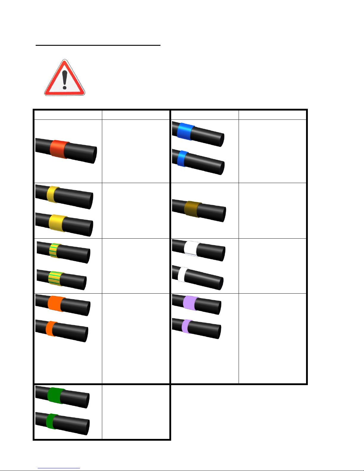
Connecting the pressure outlets :
. The connections must be made with the engine shutdown,
hydraulic pressure released and ignition key removed
Hose marking
Function
Hose marking
Function
Brakes
Bed pressure
(DE)
Bed reverse
(DE)
Close hood
(DE)
Open hood
(DE)
Load transfer
(SE)
Lock steering
(SE)
Lock steering
(DE)
Slurry door open
(DE)
Close slurry door
(DE)
Extend hydraulic
drawbar cylinder
(DE)
Retract hydraulic
drawbar cylinder
(DE)
Pressure
hydropneumatic
suspension
(DE or SE)
Return
hydropneumatic
suspension
(DE or reflux)
Pressure passive
suspension (SE)
Passive
suspension drain
(Reflux)
*SE : single acting valve (pressure /
float)
*DE : dual acting valve

Original instruction : French NT0002 V –h – 03/2012
18
Brake system :
The spreaders are equipped with three brake systems, each one assuring a specific
function.
When parking, use the mechanical hand brake. During the transport it is the
hydraulic brake that is used. The third system is a safety device for in case the
coupling breaks (a cord between the hand brake and a fixed point on the tractor).
Connect the safety cord in case of breakage of the coupling that operates the
parking brake. Check at the start of every season, the tension of the cable
connecting to the brake rods.
PROCEDURE
. Any trailer with a GVWR more than 1.5 tons is obligatorily
equipped with the braking device. It must be coupled to the
tractor braking system.
Hydraulic braking system :
Install the red hose (4) on the pressure outlet "BRAKES" on the tractor.
Ensure the proper functioning of control and check connections for leaks. Brake
pressure: 100 to 130 bar.
Reference
Element
Function
1
Brake drum
Ensures braking
2
Brake cylinders
Actuates the brake rods during transport
3
Brake cables
Is the link between the hand brake and
the brake rods
4
Hose (connected to the tractor)
Supplies the brake cylinders with oil
5
Parking brake
Hand brake
6
Coupling failure cord (attached to a
fixed point on the tractor)
Engages the handbrake should the
coupling break

Original instruction : French NT0002 V –h – 03/2012
19
Pneumatic braking system
Element
Function
Illustration
Emergency relay valve
(VRU)
Ensuring the service brake and
the automatic braking of the
trailer in case of coupling
breakage or pressure drop in the
supply line
Static corrector
(optional)
Adjusts the brake pressure, that
is the brake force, depending on
the load condition of the vehicle.
Relay valve (optional)
Allows the control circuit to
control the permanent circuit.
Shunt valve
Allows the release of the service
brake of the trailer after initiation
of automatic brake caused by the
disconnection of the hoses.
Reservoir + purge
Compressed air tank. The purge
allows the moisture in the circuit
to be evacuated.
Coupling control
controler
(yellow)
Permits the braking between
tractor and trailer
Coupling Feed
(red)
Ensuring the continuous supply
between the tractor and trailer.
Brake chamber
Ensuring the service brake
system with its front part and the
parking brake with its rear part for
the dual spring cylinder.
Pressure outlet
Used to control the pressure in
the system
N.B : The brake can also be mixed (hybrid pneumatic/ hydraulic fitting)
(mounting for 40 kmh prohibited)
Or
Or

Original instruction : French NT0002 V –h – 03/2012
20
Example of air braking system on 2 axles (40 kmh)
Installation of the drive shaft :
PROCEDURE
. All drive shafts must be equipped with safety guards in good
condition.
. Deteriorated guards must be replaced immediately
. Do not forget to install guards and to restrain them with
chains.
. Never operate a PTO without the foreseen guards.
. Wearing loose clothing may be the cause of accidents.
. During the first use, it may be necessary to adjust the length of the drive
shaft. To do this :
Ensure the correct length of the drive shaft tubes.
Tube can be damaged if the turning circle is too severe
Interlock the tubes a minimum of 4500 mm.
On transmissions there are several types of security, safety shear bolt or torque
clutches cams. In case of a shear bolt, it should be replaced by a bolt of the same
type and same quality as the original. Replacement by a stronger bolt will damage
the vehicle.
N.B : for commissioning, operation and maintenance of the transmission
(primary and secondary), refer to the manufacturer's specific instruction
manuals provided with the machine.
T
R
A
C
T
O
R
Or
Or
1 Emergency relay
2 Fixed correcteur
3 Relay valve
4 Brake valve
5 Reservoir
6 Feed
7 Control
8 Pressure
9 Brake cylinders

Original instruction : French NT0002 V –h – 03/2012
21
Electrical connections :
1- LIGHTING
The machines are equipped with standard lighting which follow the legal
requirement for road use.
Spreaders are fitted with regulation lighting, for that reason, it is necessary to
connect them to the tractor electrically.
PROCEDURE
. Never leave without checking the operation of the vehicle
lighting: your safety and that of others depend on it.
. Do not leave the wires hanging near the transmission
Connect the multipin (A) without forcing it and in the right direction, the tongue
must be in the slot.
Careful: our wiring is designed to cope with the flow of current independently to the
left and right hand lights. Depending on your tractor a bridge on your tractor socket
may be necessary. If this is the case: Rolland cannot take any responsibilty for an
overheated circuit. This modification is done by the client and is his responsibilty.
2- OPTIONAL EQUIPMENT
Connect the 3-pin plug (B) without force, the direction is indicated by the flat
section.
This socket is present on all machines equipped with electronic boxes or those
equipped with weighing or centralised lubrication.
A
Polari
B
Flat
Polarising slot
tongue
Left indicator
Not Used
Brake
Right indicator
Right light
Left light
Earth

Original instruction : French NT0002 V –h – 03/2012
22
Installing the self-drive system :
The option of self-steering axle requires the installation of a steering actuator.
Depending on your trailer, one or two clevis forks must be mounted on your tractor.
These are provided but the adaptation and installation are not covered by
ROLLAND. In fact, depending on the make and model of tractor, the forks' position
may vary slightly.
For 1 self-steering axle
For 2 self-steering axles
While the tractor is completely turned (wheel in contact with the
drawbar), verify that approximately 20mm margin at extremeties
of the undercarriage piston rods remains, i.e. that they are not
fully retracted or extended.
Installation of the clevis forks:
The axes of the cylinder swivel and the ring of the drawbar must be at a distance of :
180 mm for mounting in a single cylinder link
120 mm / 160 mm for mounting in a double cylinder link
The axis of the cylinder swivel must be decreased by :
18 mm with respect to the axis of the ring.
18
180
Axe anneau de flèche
Clevis fixed to
the tractor

Original instruction : French NT0002 V –h – 03/2012
23
120
Actuator of the rear
axle
Actuator of the front
axle
120
Axis of the
drawbar ring
160
18
Installing the cylinder :
For this operation, no pressure may be present in the circuit. If your installation has
only one cylinder, the automatic latching system allows its installation easily. Simply
attach the cylinder to the tractor and slowly steer it round to lock it. However if your
vehicle has two cylinders on its drawbar, install the cylinders manually.
The adjustment should be made with tractor and trailer coupled
and properly aligned, wheels straight, cylinder(s) attached. It is
advisable to advance in a straight line for about 10 meters.
Make sure the tractor handbrake is engaged.
.
PROCEDURE
Close the circuit selector valve(s)
Open the isolating valves of the different circuits.
Using a hand pump, raise the pressure in the different circuits
Between 20 and 35 bar for mounting a single cylinder with a diameter 40/80 (the
valve on the hand pump must be closed)
Between 20 and 35 bar for mounting two cylinders
Once the pressures are stable (a difference of 5 bar can be tolerated), close the
valves of the different circuits.
To reuse the hydraulic support, simply reopen the valve(s) selector. (make sure
the valves of the self-drive circuit are closed)
To release the pressure from the circuit, the valves on the circuit selector must be
closed, open the valves for the various circuits and open the tap of the hand
pump. The oil then returns to the pump.

Original instruction : French NT0002 V –h – 03/2012
24
Concerning follower and self-steering axles
Any self-controlled running gear can be used in steering mode. To do this, simply
place the cylinder(s) to the side(s) of the drawbar in the space provided for this
purpose. The axis ball cylinder - tractor clevis then serves to block the cylinders.
The pressure in the circuit must always be released (monitor through the
pressure gauges). For locking the follower axle, a hose, labeled yellow-green, is
located on the hose holder.
Fixation axis
cylinder ball
coupling - tractor
In the self-steering (or forced) mode, it is forbidden to use the
steering axle locking hose, as this may cause great damage to
the hydraulic system. Thus, to avoid any risk of error, it is highly
recommended not to connect this hose (marked by striped
yellow and green markings) to the tractor in self-steering mode.
. Before steering, ensure that nothing is blocking the rotation of the wheels.
It is imperative that the hydraulic system of the axles is purged of all air.
Do not exceed recommended pressures in the process of pressurizing the circuit
because the membranes of the accumulators may be damaged and no longer
fulfill their role.
Concerning the follower axles
For locking the steering axle, a hose labeled yellow-green is located on the hose
holder.
. On the highway in steering mode, it is advisable to lock the
axle(s) to avoid any risk of an accident involving an unplanned
movement of the trailer, especially when your vehicle is laden.

Original instruction : French NT0002 V –h – 03/2012
25
5 – Normal use and instructions
Above, the explicit representation of icons shown on the vehicles
representing the various risks (risk of crash, fall risk, etc. ...).
Parking:
During storage of the vehicle the observance of certain rules is mandatory for your
safety but also in order to have a vehicle ready for use when needed.
.
It is recommended to store the vehicle in a covered location.
The vehicle must be unladen on its stand.
The brakes on.
The storage area must be flat (slope of 10° maximum) and stable.
The hydraulic hoses re-connected on the hose holder.
Lubrication has been carried out (see maintenance chapter)
Lubricate extended cylinder rods (rams).

Original instruction : French NT0002 V –h – 03/2012
26
Loading :
Any damage due to overloading is in no case covered by manufacturer's
warranty.
.Never exceed the vehicle payload
.Check the good load distribution on the vehicle
.Check the balance of the load, good stability and
manoeuverability of the vehicle.
. Ensure during loading that no hard substance (stone, pieces of
wood, iron, etc.) is loaded into the spreader, it could cause
damage.
. When used in freezing weather check the mobility of the slats of the bed
before loading.
Transport
The spreaders are designed to travel at 32 km / h or 20 mph (see table) according to
the model. They are approved for the highway.
. Respect the highway code.
. Never leave without first checking the correct function of the
vehicle’s lighting: your safety and that of others depends on it.
. Check the inflation pressure of the tyres (see chapter
Maintenance).
. Moving across a hillside with a loaded hook lift can be
dangerous. To the extent possible, move with the axis of the slope. If not
possible, avoid driving with a load greater than 50% of the nominal load.
. For maximum safety, it is imperative not to exceed a gradient of 15%
(obstacles, ruts, ditches).
Bed shaft counter (hubodometer) optional..
This meter is configured for a wheel type 305 70 R 19.5. If your vehicle is
equipped with different wheels, a correction of the display of the hubodometer is
necessary to obtain an exact distance.
.Examples of correction values :
Real value = value read x correction value
For all other dimensions, please go to page 40.
Description of the
wheel
Circumference
Diameter
Correction value
18/22.5 (445 65 R
22.5)
3505
1130
1.26
500 60 R 22.5
3705
1180
1.33
550 60 R 22.5
3862
1230
1.38
600 55 R 26.5
4176
1330
1.5

Original instruction : French NT0002 V –h – 03/2012
27
Spreading
Set the PTO in motion without accelerating and bring it to normal speed of 1000
rpm. All ROLLAND spreaders are designed to operate in this regime except in
exceptional cases (540 rpm). In all cases, the plan to use is specified by a sticker on
the hose carrier at the front of the vehicle.
If the quality of the spreading is not satisfactory, several factors may be the cause,
seek the reason among the following points:
Adjust the settings relative to the dung.
The load (irregular, non-homogeneous).
The power of your tractor (too weak).
The speed of the PTO (too slow - monitor the plan). Check the flow.
If a beater jams on the deck, reverse or advance the bed to clear the beaters, stop
the machine (see § 1-1 on page 3) and manually remove the material blocking the
machine from the rear (see page 32). To perform this operation, it is advisable to
wear personal protective equipment (gloves, goggles, helmet, ...)
The controller can also be operated manually in case of failure. To switch to manual
mode you must turn the screw 1 clockwise. From the tightening of the screw the
controller switches to manual mode, then just fine tune as needed. To return to the
electrical control, simply wind out the screw entirely. In case of failure of the
distributor or control box, it is possible to connect the hoses directly to the tractor.
1
ALL WORK AT THE REGULATOR (MANUAL
ADJUSTMENT AFTER A REPAIR FOR EXAMPLE)
MACHINE MUST BE SHUTDOWN COMPLETELY
(TRACTOR ENGINE OFF, IGNITION KEY REMOVED).
TO RESTART, SEE § 1-2 on page 3).
THE SAME INSTRUCTIONS MUST BE RESPECTED IN
THE CASE OF THE MANUAL REGULATOR (SEE
PAGE 12). IN ADDITION, THE REAR WINDOW OF
THE TRACTOR CAB MUST BE CLOSED WHEN
OPERATING THE MACHINE.
(SEE, GENERAL SAFETY REGULATIONS PAGE 3)

Original instruction : French NT0002 V –h – 03/2012
28
6 – Settings
Preamble: Unplug the power supply before carrying out any adjustments (see
§ 1-1 on page 3)
Adjustments to the mechanical drawbar :
Adjustments to the mechanical drawbar :
The setting of the drawbar enables a level body according to the coupling height,
giving a greater flexibility and a maximum weight transfer to the rear axle of the
tractor.
N.B : For the first commissioning, the dealer will take care of adjusting the drawbar.
PROCEDURE
. Carry out the adjustments on an empty vehicle.
. Operate on a firm, level ground.
. Make sure the parking brake (tractor and trailer) is engaged..
. Install the safety peg above the ring bolt of the tractor..
Put the machine on chocks with the help of a jack (lifting capacity: 5T) placed at
the front of the chassis.
Remove the setting pin of the drawbar (item B).
Position the drawbar so that the spreader is level when coupled to the tractor.
The position of the drawbar will be adjusted to the next higher hole. Thus the
spreader will be slightly nose up.
Replace the setting pin.
Remove the jack.
The top hole is used for large diameter wheels, the distance between each hole
being 7cm.
Jack 5T

Original instruction : French NT0002 V –h – 03/2012
29
7 – Care and maintenance
To carry out the maintenance under good conditions, the following safety
rules must be met :
Block the wheels.
Engage the mechanical brake. (hand brake)
Unload the vehicle.
1- Check the brake system (every 6 months)
a- Parking and emergency brake
Verify the correct tension of the parking / emergency brake. The parking brake
lever should not be able to reach the last ¼ of the ratchet. If this is not the case,
tighten the cable.
Procedure for tensioning the cable :
Set the parking brake lever in the off position and ensure the
immobilisation of the vehicle by placing chocks in front and behind the wheels.
Loosen the cable clamps on one side,
Re-tension the cable
Re-tighten the cable clamps
Perform a test
If it appears that the brake rods (see fig.1 below) require too much
angle to allow for efficient braking, take up the play at the pads (see
the following: b)
b- Service brake
Check operation of the brake cylinders, make sure they are not at full-stroke and
control their mounts and the return springs (cylinders should not extend more
than two thirds of their maximum stroke or 100mm).
If this is not the case, proceed to remedy the brake linings.
To do this :
Set the parking brake lever in the off position and ensure the
immobilisation of the vehicle by placing chocks in front and behind the
wheels.
Remove the circlip at the end of the brake cam (see fig1 next page)
Disconnect the link rod of the cam.
Using a pipe wrench for example, exert a torque on the brake cam
simulating the braking.
Replace the link rod on the cam in this position.
Replace the circlip.
N.B :

Original instruction : French NT0002 V –h – 03/2012
30
If your vehicle is equipped with brake slack adjusters, bring the pads
closer by turning the bolt provided for this purpose with a 19 spanner (see
Fig. 2).In a clockwise direction close the bolt until you feel resistance and
then back off a ¾ turn (see Fig. 2).
If your vehicle is equipped with self-adjusting rods, the operation of
lining play compensation manages itself.
Check lining wear through the hole provided for this purpose.
If the pads are unusable or questionable, contact your local ROLLAND
dealer.
Fig. 2
Fig. 1
c- Check wheel hub bearings :
The bearings are wearing parts; their lifespan depends on working conditions, load,
speed and especially their adjustment and lubrication.
To check the play of hub bearings, lift the axle (vehicle shut down (see § 1-1 on
page 3) and empty) so that the wheel does not touch the ground (need for a jack
5T capacity in line under the axle) and grasp the wheel right and left trying to
move it.
Monitor after the first commissioning.
Every 2 years, verify the adjustment of tapered bearings. Excessive play may
damage the bearing seats and braking devices.
d- Checking the hub caps :
For push on caps, visually check that they are fully fitted into the hubs.
For screw caps, make sure they are properly seated at the front of the
hub.
View port - linings
Brake rod
Brake cam
Circlip

Original instruction : French NT0002 V –h – 03/2012
31
2- Maintenance of the running gear :
Maintenance work on the running gear must be performed by qualified and
competent staff with the appropriate tools and a specialised workshop
approved by the vehicle manufacturer.
General inspection
For : ½ tandem, tandem rods
Check and tighten all the nuts on the axle fixation flanges and the draw rods if
present. (follow the order of Diagram 2)
Grease the various pivot pins and the end of the springs in their slide (Figure 1).
Lubrication
Lubrication
Tightening
1
2
3
4
Plan 1 Plan 2
Case of the rocker axle or Rollfast
Check the absence of play in the axis of the rocker bar.
Lubricate the various points (14 per axis of the rocker bar or Rollfast)
14 grease nipples along this axis

Original instruction : French NT0002 V –h – 03/2012
32
3- Cleaning and lubricating :
Clean the body with copious amounts of water after each transport of corrosive or
soiled goods. After washing, follow up with a general lubrication (oil spray) and verify
the brake functions. For all cleaning and lubrication operations, the machine should
be shut down (see §1-1 of page 3)
Every 10 hours:
-Grease the bed chain drive front and rear
- Greasing of the PTO drive shaft
Every 50 hours:
-Grease the axle, the drawbar and the drive shaft bearings
1 to 3 times/year (depending on use intensity) :
- Grease the beater bearings (to the right of the TCE, at the top of the verticals
(in the upper casing)) Provide adequate means of access (see page 32)
-Grease the drive shaft bearings
The grease points are represented by red dots on the diagram below. The oil of the
various mechanical boxes (gearboxes, gearbox and bevel) should be replaced every
year or every 200 hours in accordance with the amounts shown in the "maintenance
of mechanical boxes." The recommended oil is SAE 140.

Original instruction : French NT0002 V –h – 03/2012
33
Instructions for cleaning
Caution: this operation requires special precautions in addition to those cited
throughout this document (pages 3, 17, 20 and 26 in particular) and in this chapter.
Mandatory:
Ensure the machine is stopped and the discharge of the device is
complete.
Use the side ladder for this purpose
Warning, there is no means of access to the interior of the vehicle.
If, however, an intervention inside the body is required, equipment (not
supplied) type scaffolding must be used to enter, with railings and other safety
precautions. In general, all interventions higher than the floor must be done with
adequate means of access.
All interventions, which are more toward the back of the machine, must
be done with the machine off, PTO disconnected and using personal protective
equipment (goggles, gloves etc..) recommended for the use of specific tools by
their manufacturer for example :
High pressure cleaner for washing the screws and beaters
A cutting tool to cut the strings
Etc
The rotation of the bed and all other functions (slurry door, hood) are
sometimes necessary. All our machines permit these functions independently of
the rotation of the PTO. This ensures the non-rotation of moving parts particularly
with the " autonomous control". In fact in the latter case, a connection kit comes
with the machine (see pages 10 to 13) to allow the bed to be supplied directly
with oil from the tractor.

Original instruction : French NT0002 V –h – 03/2012
34
A
B
A
B
A
B
4- Adjustment of the bed tension :
This adjustment must be performed every 50 hours of use. It prevents premature
wear of components and keeps the chains in position. To carry out the tension
adjustment of the 2-chain there are 2 stretchers (A) outside the skip, for the 4-chain,
there are the two tensioners (A) and 2 more (B) in the middle.
Loosen the counter-nuts A
The tensioning of the bed is done by compressing the spring by tightening the
nuts B
Proper tension translates into a lift-off between 5 and 10 millimeters of the first
bar of the bed in relation to the guide plates under the spreader.
Tension control to be performed every 10 hours (adjust tension if
necessary)

Original instruction : French NT0002 V –h – 03/2012
35
5- Steering axle :
Checking and adjusting the alignment
Immobilise the vehicle, the steering axle well inline, lock cylinders retracted, on a
level surface.
Measure the distance between the front wheels and the rear follower axle. The
same value should be found.
If this is not the case, unblock the 2 lock nuts of the coupling rod, and rotate it in
order to get the distance at the front to be identical to that at the back.
Tighten the lock nuts firmly.
The coupling rod
Lock nuts
Adjusting the locking cylinders
Periodically check the cap-nut and its lock-nut. After the alignment, proceed to
adjust the locking cylinders as follows
Unscrew the lock-nuts
Screw on the cap nuts.
Develop and maintain pressure in the cylinders.
Unscrew the cap nuts to have them pressing against the stops
Screw down the lock-nuts firmly in order to lock the setting.
Cap-nuts
Lock-nuts

Original instruction : French NT0002 V –h – 03/2012
36
6- Maintaining the regulator and hydraulic unit :
Shutdown the vehicle (see §1-1 of page 3)
Check the oil level and tightness of the tank. Remember to change the oil and
regulator filter every year. To change the filter, unscrew the protection bowl (red).
Clean the inside of the bowl with a cleaning agent (do not use cloth or paper
towels), change the filter and then replace the bowl.
Check the oil level of the gear-box. Make a first oil-change after 50 hours of use
and thereafter annually at least.
Check the condition of the hose.
7- Bed control :
Shutdown the vehicle (see §1-1 of page 3)
Check the wear of chain drives and bearings, lubrication is mandatory
(centralised lubrication).
Check the condition and fastening of the bed slats.
8- Transmission maintenance :
The maintenance of this element is primordial for your safety.
Shutdown the vehicle (see §1-1 of page 3)
Check as often as possible the protection cover of the universal joints
Lubricate the various elements of the PTO and the bearings of the shaft
(periodicity page 31).
Check the wear of shims on the drive shaft and the lubrication.
Lubricate also the universal joints at the ends of the angle transmissions.
To optimise the function directly from the tractor a reflux without brake (push-pull
type) is recommended.
- Output tractor direct about 60L/min for a manual control type MTKA,
otherwise risk of overheating and possible engine failure.
- Output tractor 80L/min for a proportional type regulation with an
electrical control in the cab
- Every year, change the oil in the reservoir, change the regulator filter
and change the unit mesh filter.
WORK ON ANY ELEMENT OF
TRANSMISSION (SHAFTS, CARDANS,
BEARINGS, ...) MUST BE DONE ONLY ON A
FULLY SHUTDOWN MACHINE (STOP THE
TRANSMISSION AND TRACTOR ENGINE).
REMOVE THE KEYS

Original instruction : French NT0002 V –h – 03/2012
37
9- Replacing the wearing parts:
The spreader assembly contains parts that wear and must be replaced regularly,
there is no advised service life for these parts as they wear out faster or slower
depending on the type of manure or according to settings made by the operator.
Element
Quantity (per beater or per disc)
Wear arm - disc
3
Beater point
C8
15
C10
19
C11
20
C12
20
C13
22
C22
21
C23
19
TCE
15
2
2 types of blade: left and right
Deck wear strips

Original instruction : French NT0002 V –h – 03/2012
38
10- Maintenance of mechanical housings:
Shutdown the machine completely (see § 1-1 on page 3)
Change the oil in the various mechanical boxes every year or after 200 hours using
the SAE 140 respecting the following quantities:
Assembly
Housing
(In the direction of travel)
Oil quantity (in litres)
C8
Middle
1.2
Left
2.2
Right
2.2
C10
Middle
1
Left
1.8
Right
1.8
C11
Middle
1.2
Left
2.2
Right
2.2
C12
Middle
1.2
Left
2.2
Right
2.2
C13
Middle
1.2
Left
2.2
Right
2.2
C22
Middle
1.2
Left
2.2
Right
2.2
C23
Middle
1.2
Left
2.2
Right
2.2
TCE
Middle
1.2
Left
2.5
Right
2.2
Exterior transmission
angle
1.2
Beater (x2)
0.8
TCEI
Middle
1.8
Left
1.5
Right
1.8
Exterior transmission
angle
1
Beater (x2)
0.7
Bed
Bed drive casing (right or left
and right)
2.8
Hydraulic unit
Gear pump casing
0.3
Visco 400

Original instruction : French NT0002 V –h – 03/2012
39
11- Wheels and tyres:
Check the wheel nuts and tyre pressures regularly
Inflation
Proper inflation of tyres allows optimum grip, comfort and performance. Also the
tyres will last longer and the surfaces will be preserved.
We strongly discourage:
- An under-inflation, which distorts the carcass and may cause a tyre failure.
- The over-inflation which reduces the area of contact with the ground
resulting in a loss of adhesion. In addition the casing is more sensitive to
shocks.
Assembly
Mount the tyres only on the rims they are designed for.
Use rims clean and in good condition, working with clean surfaces.
Use the appropriate tools for the tyres and rims.
To facilitate assembly and disassembly, lubricate the seating (green) and the
beads of the casing (black) with a suitable product as shown in the sketch below.
With a new tyre, use a new inner tube. Use an inner tube corresponding to the
size of the tyre.
After mounting a tyre, ensure the correct centering of the tyre on the rim: if this is
not the case, inflate, deflate and inflate again until the centering is good. Always
use the maximum pressure for positioning the beads on the rim seat 2.5bars (35
psi). Then adjust the pressure to use or to store.
When transporting the equipment by road, rail or boat, you must inflate the tyres
to 2.5 bar (35 psi) to avoid damage from the mooring systems.

Original instruction : French NT0002 V –h – 03/2012
40
Features of tyres available for the Rolltwin :
Type
Service
pressure
Max. load at
40km/h*
Dimension
s
Correction
value
hubodometer
18 4/30 A324 Alliance
3.2
4080
1550x467
1.68
18 4/34 A324 Alliance
4.2
4200
1632x467
1.77
18 4/38 A356 Alliance
4.8
6270
1733x516
1.88
23 1 R26 Prostor
2.8
5000
1605x587
1.74
23 1/26 A347 Alliance
2.8
5030
1605x587
1.74
620/75 R26 A375 Alliance
3.8
6325
1595x625
1.73
650/60 R 34 Els Nokian
4
9400
1644x650
1.78
650/65 R 30.5 A380 Alliance
4
9660
1623x650
1.76
620/75 R 30 Michelin
4
5600
1710x604
1.85
650/75 R 32 A360 Alliance
3.9
7245
1793x645
1.94
650/65 R 26.5 A360 Alliance
4
9110
1520x650
1.65
580/70 R 38 A370 Alliance
3.3
5950
1817x577
1.97
650/65 R 30.5 Michelin
Cargo
4
9660
1623x662
1.76
650/65 R 34 Els Nokian
4
9400
1645x650
1.78
650/65 R 26.5 A380 Alliance
4
9110
1520x650
1.65
710/50 R 30.5 Michelin
Cargo
4
8840
1495x728
1.62
Characteristics of tyres available for the Rollmax
Type
Service
pressure
Max. load at
40km/h*
Dimension
s
Correction
value
hubodometer
550/60 22.5 Diagonal/Divers
3
5300
1360x645
1.48
560/60 22.5 A380 Alliance
4
6710
1245x554
1.35
560/60 R 22.5 Nokian
country
4
6300
1244x560
1.35
560/60 R 22.5 Michelin
cargo
4
6290
1250x560
1.36
580/65 R 22.5 Nokian
Country
4
7250
1300x580
1.41
600/55 26.5 16PL
4
6390
1348x626
1.46
600/55 R26.5 Michelin
Cargo
4
6390
1348x626
1.46
620/60 R26.5 Nokian
Country
4
7900
1400x620
1.52
600/55 R26.5 A380 Alliance
4
7450
1350x620
1.46
650/55 R26.5 A380 Alliance
4
7900
1360x645
1.48
* not all vehicles are approved to 40 km / h, there are versions 40km / h or 32 km / h.
For the type of vehicle, check the sticker on the left rear of the vehicle or the
certificate of conformity.

Original instruction : French NT0002 V –h – 03/2012
41
1
4
2
2
3
12- Lighting:
When replacing a bulb, be sure to respect the indicated power and the connection of
the wire.
reference
function
colours
1
Number-plate lighting
white
2
Brake lights + stop
red
3
Indicators
orange
4
Reflector
red
Note: There is an option to automatically protect the lighting against dung
spray. The lights remain in good condition and well visible to people behind
the vehicle on public roads. The principle is: the protection is activated
whenever the moving floor is engaged.
ENSURE THE ABSENCE OF THIRD PARTIES IN THE AREA OF
PROTECTION ACTION.

Original instruction : French NT0002 V –h – 03/2012
42
8 – Assembly
Installation of a Beacon :
The beacon can be powered via the sidelights, in some cases it can be powered via
a 3-pin plug.
If the power is supplied via the side lights, the maximum power of the beacon is
21 watts
(text in triangle: Caution! Revolving light 21 watts only)
C
C
C
A
A
A
U
U
U
T
T
T
I
I
I
O
O
O
N
N
N
!
!
!
R
R
R
E
E
E
V
V
V
O
O
O
L
L
L
V
V
V
I
I
I
N
N
N
G
G
G
L
L
L
I
I
I
G
G
G
H
H
H
T
T
T
2
2
2
1
1
1
W
W
W
A
A
A
T
T
T
T
T
T
S
S
S
O
O
O
N
N
N
L
L
L
Y
Y
Y

Original instruction : French NT0002 V –h – 03/2012
43
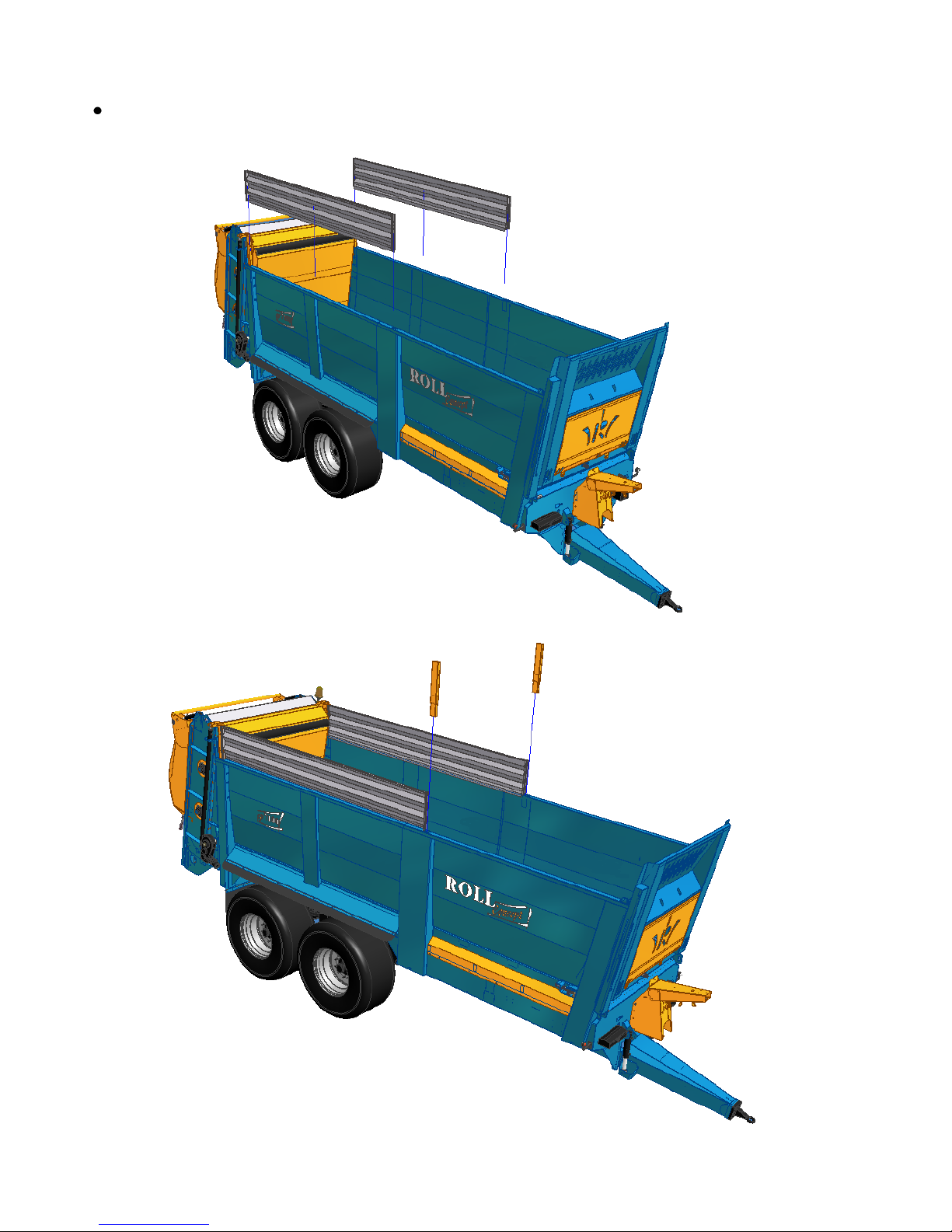
Equipment assembly :
These operations are the responsibility of the dealer, as he alone is
trained and approved. Means of access to the machine must be in
place to ensure there are no risks of falling, among others.
PROCEDURE
After having smeared with grease, install the rear posts. The grease facilitates
their mounting and demounting because adjustments are optimized to ensure the
tightness of the assembly. Fix the sheet metal cladding to the posts mounted at
the rear (side inner body).
Example of means of access for the
installation of silage equipment
Original instruction : French NT0002 V –h – 03/2012
44
Install the rear panels, the middle pillars then fix them with the bolts provided for
this purpose.

Original instruction : French NT0002 V –h – 03/2012
45
Install the front risers followed by the front pillars and then fix them with the bolts
provided for this purpose.

Original instruction : French NT0002 V –h – 03/2012
46
Procedure for mounting the silage doors (option Rollmax)
Before installing your silage door, you must remove the beater frame of your
spreader. The operation must be performed by your ROLLAND dealer, the only
ones authorised, trained and to have the tools.
Procedure for removal of the tool frame
Disconnect the secondary drive shaft
Using slings, hook the framework to an overhead crane (minimum
capacity 2.5 tons for the slings and the crane). The attachment points are
specified in the following diagram. The weight of each subassembly is
specified by stickers.
Loosen and remove the fixing bolts of the body.
Remove the frame using the crane and place it on its support. Fix it to
the support, using the nuts and strap(s) provided. After checking the tightness
and stability, the slings can be removed.
In the absence of a frame support, place the frame flat on the floor on
the hatch side.
Silage panels :
After having smeared with grease, install the rear posts. The grease
facilitates their mounting and demounting because adjustments are optimized
to ensure the tightness of the assembly. Fix to the body of the spreader using
the bolts provided.
Then install the panel (weight approximately 80 kg) using a hoist or a
loader. Lock in place with the pins provided.
Attachment points for handling
the spreading assembly
Optional assembly support

Original instruction : French NT0002 V –h – 03/2012
47
Silage Door « LOULOU »
After having smeared with grease, install the side panels. The grease
facilitates their mounting and demounting because adjustments are optimized
to ensure the tightness of the assembly. Fix to the body of the spreader using
the bolts provided.
On the ground assemble the panel with the top rail by means of the
axes provided. Be careful to put in place the pins to lock the assembly.
By means of a crane, a hoist or a loader put the assembly in place,
panel + traverses. Then fasten the side panels using the bolts provided.
Complete by installing the cylinders with the drum on the body side.
For all operations carried out at heights, a means of access, type scaffolding,
must be available, respecting the standards for this type of equipment and
respecting the standards for this type of product (railings, etc ...).
The cylinders for opening the silage door "LOULOU" are fitted with
dual control valves. Beware of any residual pressure present
between the valve and cylinder.
Left side
panel
Right side
panel
Lubrification
Lubrification
Panel
Attachment
points for
handling
Top rail

Original instruction : French NT0002 V –h – 03/2012
48
9 – Annexes
ANNEX 1
INSTRUCTION FOR USE OF THE HYDRAULIC DRAWBAR
SUSPENSION
1- PRESENTATION OF THE SYSTEM
All drawbars with a damping system rather than a mechanical leaf
spring but consisting of elements using hydraulic technology are called drawbar with
hydraulic suspension.
The system is governed by the tractor. The operator can correct at any
time the height of the drawbar.
2- OPERATING PRINCIPLE
The system is mainly composed of the following elements :
Component
Quantity
Illustration
Suspension cylinder
2
A drawbar suspension
unit equipped with 2
diaphragm
accumulators
1
Drawbar
1

Original instruction : French NT0002 V –h – 03/2012
49
The various elements are assembled according to the following plan :
3- RECOMMENDATIONS FOR SETTINGS AND USE
The drawbar should be adjusted so that the chassis of the trailer is
horizontal.
However, some cylinder movement must be possible to absorb dynamic
impacts ( 3cm)
2 modes of operation are possible :
The operator predefines once and for all its coupling height. In this case he
may leave the supply hoses unconnected on the tractor. It should be noted
that the drawbar works in closed circuit; that is to say that when loading the
spreader, the spreader will sink down, when you start tipping, the cylinders will
again be deployed and no correction will be possible.
This method is strongly discouraged despite a possible saving of a
distributor on the tractor.
Or the user leaves the hoses permanently connected to the tractor. This will
allow an instant correction of the height of the drawbar to compensate for the
movement of the cylinders due to the load variation in the vehicle.
Such use is the "normal" use of the system.
By working this way we obtain the maximum suspension flexibility.
N.B : 2 adjustments are possible at the upper catch of the cylinder. The
method for changing the catch is identical to that of the sprung drawbar (see
page 28)

Original instruction : French NT0002 V –h – 03/2012
50
ANNEX 2
INSTRUCTIONS FOR THE PASSIVE SUSPENSION OF AN
Axle (closed circuit)
1- PRESENTATION OF THE SYSTEM
All axles are equipped with an independent damping system that are
said to be with passive or closed circuit suspension.
.
The circuit is completely independent of the tractor. The suspension is
set once and for all (even though it is changed occasionally). The adjustment is
made so that an optimal displacement is supported. The cylinder movement being
200 mm, the optimal displacement is ± 100 mm.
The user cannot correct the height of his vehicle on the move.
2- OPERATING PRINCIPLE
The system is composed mainly of the following components:
4 suspension cylinders for a vehicle with 2 axles (6 for a 3-axled
vehicle)
1 hydraulic suspension control block
2 piston accumulators
The system is composed mainly of the following components:
Component
Quantity
Illustration
Suspension cylinder
4 cylinders for a vehicle
with 2 axles (6 for a 3-
axled vehicle)
Passive suspension
block
1
Accumulators
2

Original instruction : French NT0002 V –h – 03/2012
51
2 comments :
A system for counter roll of the vehicle is provided in the assembly. Oil will never
"take the easy route". The load will constantly be equal over the four wheels, which
allows us also to "dispense" with tipping stabiliser.
The pressure relief valve is intended for smoothing out any abnormal pressure
peaks (violent dynamic shocks).
3- RECOMMENDATIONS FOR SETUP AND USE
a. To increase the height of the suspension (raising the body) :
To add oil to the suspension system (if, for example, the height is
considered insufficient), proceed as follows:
Connect the hose identified by a marking (long green) to the tractor.
Open the two outer taps of the block (see photo). The middle tap must be
closed.
Supply the oil circuit via the hose connected to the tractor until the required
height is achieved.
Close the two outer taps again and open the middle tap.
Release the residual pressure present in the hose by positioning the tractor
distributor on "float"
Disconnect the hose (long green) from the tractor.
Only the return drain hose (short green) remains connected.
WARNING Note that the height of the skip will vary depending on
the load present inside.

Original instruction : French NT0002 V –h – 03/2012
52
b.To decrease the height of the suspension (lower the body) :
To remove the oil from the suspension system (for example, if the
height is considered too high), proceed as follows:
Connect the hose identified by a marking (long green) to the tractor.
Open the two outer taps of the block (see photo). The middle tap must be closed
Set the relevant distributor of the tractor on position "float" until the required
height is achieved.
Close the two outer taps again and open the middle tap.
Release the residual pressure present in the hose by positioning the tractor
distributor on "float".
Disconnect the hose (long green) from the tractor.
Only the return drain hose (green short) remains connected.
RECOMMENDATIONS FOR USE :
The hose used to adjust the height of the skip should be connected only in case of
need to work on the suspension. In normal operation, this hose should be stored on
the hose holder.
In contrast, the hose "drain" (oil reflux by high over pressures) must be permanently
connected to the tractor.

Original instruction : French NT0002 V –h – 03/2012
53
ANNEX 3
INSTRUCTIONS FOR THE HYDROPNEUMATIC SUSPENSION
OF AN AXLE (open circuit)
PRESENTATION OF THE SYSTEM :
All undercarriages equipped with a damping system with instant
automatic level correction are said to have hydropneumatic suspension.
The system is permanently coupled to the tractor. The ideal is to
provide a single acting valve (LS if possible) and a free return to the source.
Pressure can also be taken at the pump outlet without using a distributor since a
continuous pumping is required.
The vehicle corrects its height instantly, which is to say that when
loading the vehicle, the hydraulic system will demand the tractor to re-adjust the
height of the skip and vice versa, during unloading, the system will return oil to the
tractor..
PRESENTATION OF THE SYSTEM :
2-1 : The system is composed mainly of the following components :
Component
Quantity
Illustration
Suspension cylinders
4 cylinders for a
vehicle with 2 axles (6
for a 3-axled vehicle)
Diaphragm accumulators
4 cylinders for a
vehicle with 2 axles (6
for a 3-axled vehicle)
Hydraulic suspension
control block
1
Pressure compensator
1
Vehicle level detectors
2
Cab-located control box
1

Original instruction : French NT0002 V –h – 03/2012
54
2-2 Functions of the buttons on the control box :
Red button:
Up manual raising of the vehicle
Down manual lowering of the vehicle
Green button :
set to automatic mode or system initialisation (chapter 3-1)
2-3 Hydraulic connection diagram :
For confidentiality reasons, we will not disclose our hydraulic circuit
diagram. In case of hydraulic concerns, please contact us..
Comment :
- A system for counter roll of the vehicle is provided in the assembly. Oil
will never "take the easy route". The load will constantly be equal over the four
wheels, which allows us also to "dispense" with a tipping stabiliser.
-The pressure relief valve is intended for smoothing out any abnormal pressure
peaks (violent dynamic shocks).

Original instruction : French NT0002 V –h – 03/2012
55
3. RECOMMENDATIONS FOR SETUP AND USE
3-1 Initialisation of the system :
Like with any electronic control system, an initialisation is required so
that the system is able to instantly know its position relative to its upper and lower
limits.
The initialisation consists of the detection, validation and memorisation
of the upper and lower limits.
- Initialisation procedure :
A blinking 1-1 appears on the box (see decoding blinks p8-9)
Using the red button, fully raise the suspension manually. Do not release the button
until the cylinders are completely deployed (200 mm travel)
Wait 2 seconds in the upper position.
Using the red button, fully lower the suspension manually. Do not release the
button until the cylinders are completely retracted (the vehicle must be
horizontal)
Wait 2 seconds in the lower position.
Return to the "auto" mode by tilting the green button.
The vehicle will automatically find its position and the LED lights permanently on
the box
Remarks :
The initialisation parameters are stored in the box. It is not necessary to restart the
process at every power up of the system. Initialisation has already been done in the
factory. An initialisation on-site may be required only in case of an intervention on
any of the system components.
If the vehicle does not automatically find its position and blinking 1-1 on the box
indicator continues, it means there is a problem at one of two sensors at the rear
(bad adjustment range) contact us.
3-2 : Decoding the blinking of the box indicator :
When the control box light flashes, the operation is not in a "normal" state.
Either the system is in its initialisation phase (blinking 1-1)
Or the system has detected an anomaly. The system therefore closes down.
No action is possible (automatic or manual mode).
The system is able to detect the following defects :
Failure or breakage of the wire link of the position sensors (electrical
connection)

Original instruction : French NT0002 V –h – 03/2012
56
Overload or breakage of the wire connection of the solenoids (electrical
connection)
If one of these fault situations occurs, the lamp flashes and the solenoid control
switches off for safety reasons. Similarly, in manual mode, no function can be
executed.
The user must validate the fault by switching off the power to the electronics module
for 3 seconds and then putting it back on.
Flashing signals & fault codes provided by the box indicator :
Example for fault code "2-1"
:
Defect left sensor
Decoding table of the signals emitted by the box indicator:
Indicator signal
Components to be
checked
Possible cause of the defect
Permanent signal
Automatic mode, no defects
‘’1-1’’
Initialisation mode, no defects
‘’2-1’’
Left position sensor
Wire link broken or not connected.
Output signal of the position
sensor out of range, check the
mechanical adjustment
‘’2-2’’
Right position sensor
Wire link broken or not connected.
Output signal of the position
sensor out of range, check the
mechanical adjustment
‘’3-1’’
Solenoids
- WSL (WS1)
- WSR (WS2)
Wire link broken or not connected.
Possible overload
Check the connection LGND
‘’3-2’’
Solenoid WK
Wire link broken or not connected.
Possible overload
Check the connection LGND

Original instruction : French NT0002 V –h – 03/2012
57
REMARKS :
Several options can be grafted onto this system.
4-1 : Option lift axle :
An option "lift axle" is available on this type of suspension. This option
relieves the front axle or lifts the front wheels completely.
This function replaces fully the weight transfer (or tipping stabiliser)
.
: If vehicle is equipped with a steering axle (or forced follower), it is
strictly forbidden to raise the front axle at a medium or high forward
speed (on the highway). The function should be used only when tipping
or by lack of grip traction on the ground, for example, as in the case of
the spreader.
4-2 : Load weight option :
A load weight option is available for this type of suspension.
A battery of three pressure sensors measures the hydraulic pressure at
different locations within the system. This pressure information is transcribed to a
box in the cabin which gives us information on the load in the vehicle.
A patent for this system has been applied for by Ets Remorques ROLLAND

Original instruction : French NT0002 V –h – 03/2012
58
Date
Operation
Remark
Initial
-Check the wheel nuts
After 50 km, then 2 times per year or at
the beginning of each campaign.
- Check inflation pressures
2 times per year or at the beginning of
each campaign.
- Check tightness of the axles
or the rocker pin
2 times per year or at the beginning of
each campaign.
- Lubrication of the points
indicated in the instructions
Verify before each use
- Check the correct tension of
the service brakes, the
emergency and parking
brakes.
Adjust the play as necessary
Operations to be performed at the start
(the DEALER)

Original instruction : French NT0002 V –h – 03/2012
59
Maintenance log
Date
Operation
Remark

Original instruction : French NT0002 V –h – 03/2012
60
11- EC declaration of conformity for machinery
(According to Annex IIA of the Machinery Directive 2006/42/EC)
Manufacturer : Ets ROLLAND
Address : Z.A des Landes 29800 TREFLEVENEZ
Name and address of the person authorised to compile the technical file:
Name : Béatrice LE GALL
Address : Z.A des Landes 29800 TREFLEVENEZ
Hereby, we declare that
The machine :
- Make : ROLLAND
- Commercial designation:
- Type :
- Serial no. :
complies with the relevant provisions of the Machinery Directive (2006/42/EC).
Furthermore, we declare that
the following (parts / sections of) harmonised European standards were used..
-EN ISO 12100-1 & 12100-2
TREFLEVENEZ,
Name and position of the signee
Béatrice LE GALL
CEO

Original instruction : French NT0002 V –h – 03/2012
61
A copy to be stored in this manual
OPERATOR
Name : ……………………………………………………………………………………………….
Address : ………………………………………………………………………………………………
Postcode : …………………City: …………………………..Country………………………………..
Telephone : ……………………………… Mobile tel. …………………………………
Fax : ………………………… Email : ……………………………………………………………….
VEHICLE
Vehicle type : …………………………………………………………………….………………
Serial N° (on the invoice or the conformity plate) : ………………………………………………….
Date of purchase : …………………………………………………………………………………….
Date of delivery : …………………………………………………………………….……………….
WARRANTY CONDITIONS
Our vehicles are guaranteed for 1 year from the date of delivery. Conditions of use are specified in
the booklet of commissioning supplied with the vehicle. In all cases the user must observe the
rules of use prescribed, otherwise the warranty will not be accepted. Travel and transport are not
covered by the warranty. Only fully paid vehicles will benefit from the warranty. In case of
problems the user must first contact the dealership.
I certify having read the commissioning and maintenance manual and undertake to
comply with the instructions contained therein, to qualify for the 1 year warranty
Name and signature of the commissioner : Signature of the operator :
Your opinion is of utmost importance
Help us evovle by replying frankly to our question : (*check according to your choice)
Good
Average
Bad
Delivery respected
Delivery quality
First impressions of machine
Satisfaction of first use
Your decision to buy : (* please number from 1 to 3)
Quality / Price
Design of product
Dealer relations
Delivery
Reputation of brand
Quality of brand
Reliability of brand
Your comments : …………………………………………………………………………………............
……………………………………………………………………………………………….....................
…………………………………………………………………………………………………………….
12- CERTIFICATE OF WARRANTY - DECLARATION OF
COMMISSIONING
 Loading...