


1
Dear Client,
You have just purchased a ROLLAND spreader.
We would like to thank you for the trust you have placed in us.
ROLLAND spreaders have been studied so that their spreading
technique can be maximised. They are the product of our technology and
experience in this field.
This manual must be considered as forming an integral part of your
spreader.
For proper usage, and to be able to take advantage of all of your
spreader’s capability, we recommend that you read this manual carefully,
and adhere strictly to all of the instructions contained herein.
The correct functioning and durability of your spreader will depend
on this, as will your safety and that of others.
Keep this document in its entirety should you need to consult it in due
course. This must always be kept in the spreader, even in the event that it is
resold.
Failure to adhere to the instructions contained herein release both the
manufacturer and seller from all liability.
We reserve the right to add at any time those modifications that we
deem useful for our products etc, without the obligation to previously
delivered products or those under construction. We also reserve the right to
modify without forewarning the models defined in our catalogues, leaflets
or appearing on our web site.
Please accept our best wishes and most sincere thanks.
Z.A des Landes
29800 TREFLEVENEZ - FRANCE
Tél. : 00 33 (0)2 98 85 13 40
Fax : 00 33 (0)2 98 21 38 15
www.remorquerolland.com
Notice originale : Français NT0002 V –p – 03/2014

2
Contents
1-Safety Instructions……………………………….………………….3
2-Warranty Conditions…………………………………………………4
3-Vehicle Presentation……………………………………………….5
-Usage Scope
-Vehicle Identification
-Technology and Options
4-Implementation…………………………………………………...20
5-Standard Usage and Counter-Indications……………………….….29
-Parking
-Loading
-Transport
-Spreading
6-Adjustments……………………………………………………….32
-Jib
7-Servicing and Maintenance……………………………………….34
-Braking Systems
-Ro-Ro Transport
-Cleaning / Lubrication
-Regulation of Belt Tension
-Tracker Adjustments
- Maintenance Regulator and Hydraulic Power Stations
-Consumable parts
-Maintenance of Electrical Boxes
-Wheels and Tyres
-Lighting
8-Assembly………………………………………………………….48
-Rotating Warning Lights
-Equipment
9-Annexes………….………………………………………...…………..54
-Hydraulic Jib
-Passive Suspension
10-Maintenance Log……………………………………….……………59
11- Declaration of Conformity.……………………………………....... 61
12-Warranty Certificate – Service implementation declaration …….62
Notice originale : Français NT0002 V –p – 03/2014

3
1 – Safety Instructions
Before putting into service, please study the operating instructions and respect safety
guidelines!
In these user instructions all hazards and risks to which
operators or other exposed persons are subject to have been
highlighted by this symbol.
Glued onto the spreaders, safety signs indicate
how to use the machine without danger:
Respect for the notices = safety
Standard Usage
The spreader has been designed and
manufactured for the standard usages
described in this manual
Four situations are defined herein: Parking,
loading, transport and spreading (chapter 5)
Nonetheless, a certain number of foreseeable
non-conformity scenarios are questionable
and specifically forbidden. The manufacture
will not be for damages resulting from these
actions.
It is of the utmost importance to respect the
contingency regulations against accidents as
well as the other applicable legislation in
force in terms of safety, health provision in
the workplace and the Highway Code.
The manufacturer waives all liability with
respect to damages caused as a result of an
unauthorised modification of the machine.
General Safety Regulations and
Contingency Plan against Accidents.
1. Definition of the vehicle’s consignment:
before undertaking any actions on the
machine, switch off the engine, release the
hydraulic pressure, apply the parking
brakes (tractor AND trailer) and remove
the keys from the ignition.
2. Prior to starting the tractor's engine, take
care to ensure that the power take-off is
not engaged and that all safety devices
have been equipped and are in perfect
working order.
3. Never disengage or deactivate safety
device. For adjustments, servicing and
maintenance, the procedures described in
the manual must be strictly adhered to
(above all chapters 6/7.
4. It is wholly forbidden to pass under the
vehicle when operational.
5. The machine’s usage is done so entirely at
the responsibility of the driver. The
absence of third parties in the vicinity of
all manoeuvres must be guaranteed.
6. Given the residual risks from collisions or
damage at the spreader apparatus (AND in
its projection area) and that it is
technically impossible to protect it (at the
very least during the working phase=, it
falls under the responsibility of the driver
to ensure that no third parties are present
in the environs when the machine is in
movement.
7. The driver must be fully empowered to
use the machine in the most appropriate
conditions.
Notice originale : Français NT0002 V –p – 03/2014

4
2 – Warranty Conditions
In order to benefit fully from the manufacturer’s warranty, please make sure
you follow the maintenance operations and utilisation advice provided in this
manual. Should any problems arise, the user must contact the dealership.
Warranty Conditions:
Our spreaders are guaranteed for parts and labour for one year, counting
from the date the machine is into service.
Under no circumstances can ROLLAND S.A. be held responsible for an
incident arising from the failure to respect these instructions for handling,
servicing or maintenance of the machinery.
The guarantee is valid only for the supply and replacement of defective
parts.
The warranty is invalid and we waive all responsibility in the following
instances:
1°) where the machine has been modified using elements constructed outside
of our workshops or those not manufactured by our distributers without our prior
authorisation.
2°) where the original serial number has been falsified.
3°) where the factory assembled pieces produced by ROLLAND have been
disassembled and replaced by parts of a different origin.
4°) where breakdowns and malfunctions are the result of negligence, misuse,
overloading, including even passengers, the lack of operational knowledge on
the part of the user, or due to the introduction of a foreign body into the machine
during operations or failing to lubricate it properly.
Repairs, modifications or replacement of pieces during the warranty
period cannot extend the duration of the warranty for the materials.
Following the receipt of your vehicle, make sure that this is in all points,
compliant with the technical specifications and that this has not suffered any
damages.
In order to speed up the guarantee implementation process
“THE GUARANTEE IMPLEMENTATION DECLARATION” accompanying
this technical notice must be completed and returned in the month
following delivery.
Notice originale : Français NT0002 V –p – 03/2014

5
PTAC _ _ _ _ kg
PV _ _ _ _ kg
3 - Presentation of the vehicle
This manual is standard for all ROLLFORCE and ROLLMAX spreaders from the ROLLAND
range. It has been designed with the aim of giving you all the necessary information on the
vehicle that you have just purchased and to get the best from it.
DESCRIPTION :
The spreaders are all fitted with either a “ROLLAND” sturdy suspension beam , or they may
also be fitted with a "ROLLFAST” hydraulic suspension rod.
These are mounted onto a chassis fitted with an adjustable, spring, or hydraulic jib.
Identification :
To know the features of your trailer, please refer to the sticker board attached below the right
front side of your vehicle. A plate with a self-adhesive sticker will also state the total
authorised load weight (TALW) and the empty weight (EW).
A cold stamping (serial number) is fitted under the vehicle's chassis.
This serial number is necessary all warranty exchanges with your dealership or the factory
MAX WEIGHT STICKER
DISCPLATE
Notice originale : Français NT0002 V –p – 03/2014

6
Towed agricultural vehicles are governed by two different regulations:
The Labour Code
The Highway Code
Rolland’s vehicles come supplied with their official documentation and a label containing the
EC conformity stamp. These two documents verify that the two sets of regulations have been
adhered to.
In addition to this label and depending on the options selected, complementary markings
(TALW, hydraulic weighing or on rod gauges, 1,2 or 3 axles, roll-control…).
Notice originale : Français NT0002 V –p – 03/2014

7
1
Chassis
7
Ro-Ro Transport
2
Front Deck
8
Spiked roller
3
Protective Hood
9
Hatch
4
Front Nose
10
Spreader Frame (2100Kg maxi)
5
Jib
11
Spreader Deck
6
Jib regulator
ROLLFORCE
ROLLMAX
Sideways View
ROLLFORCE ROLLMAX
Front and rear view
Notice originale : Français NT0002 V –p – 03/2014

8
Rollforce
Jib
Rollmax
Jibs
Swivel ring
(std)
Flat ring
DIN Ring
K80 Spoon Ring
Technology and options available:
Demount Ring
Jibs with 8 hole interfaces allowing for the mounting of several types of rings: flat, swivel,
spoon, DIN).
Notice originale : Français NT0002 V –p – 03/2014

9
Simple axle
(ROLLFORCE)
Undercarriage
(option on
ROLLMAX
5420, 6325
and7130)
Offset pin bogie
beam (standard
on ROLLMAX
5420, 6325
and7130)
Semi - Tandem
(option on
ROLLFORCE)
Rod Tandem
(option sur
ROLLMAX)
Triple Axle
(standard on
ROLLMAX
8735)
Rollfast
(option on
ROLLMAX)
Direction of Travel
Haulage :
Notice originale : Français NT0002 V –p – 03/2014

10
Power Source
Function
Command
n° d'avance
1) Open tractor :
operates due to the tractor’s
coupling connectors
1) Base:
Forward drive belt solely
Manual adjustment
110
Without display
111
With display
112
With display+DPA
113
2) 2 functions :
With display
Without display
121
With display
122
With display+DPA
123
3) 3 functions :
forward drive belt + hatch
+fume hood
Without display
131
With display
132
With display+DPA
133
2) Pump:
The pump is mechanically
activated using the power take-off
and multiplier located upwind
(during repairs, troubleshooting or
servicing, the coupling elements
may be connected to the traction,
as per the basic diagramme below).
1) Base:
solely with forward drive
belt
Without display
211
With display
212
With display+DPA
213
2) 2 functions :
forward drive belt + hatch
Without display
221
With display
222
With display+DPA
223
3) 3 functions :
forward drive belt + hatch
+fume hood
Without display
231
With display
232
With display+DPA
233
N.B : To carry out this operation in reverse it is necessary to invert P and T1 either push-pulls 1 and 3 on
the tractor.
Flexible repair
kit
Towards tractor
Do not forget to
Advancing : There are several types of forward movement, and in each case several of these can be
managed from the junction box in the cabin as well as from the tractor control unit which is always on
standby. See the table below for the current existing combinations : Troubleshooting tractor repairs
(Insulation pump ).
connect the coupling
Procedure for carrying out traction repair: 1- Disconnect the push-pull 1 and 2 and push-pull 3 and 4.
2- Connect push-pull 2 and 4 between them with the help
of connector kit K1.
3- Connect push-pull 1 with one with one of the two
troubleshooting connectors on the pressure side of the
tractor distributor.
.
Notice originale : Français NT0002 V –p – 03/2014
4- Connect the push-pull 3 with one of the two
troubleshooting connectors on the return side of the
tractor distributor.

11
Rest on the knurled nut to
perform AR manual
operation
Use an allen key and tighten
the hc screw to empty the
machine manually (manual
repair).
For utilisation in LS mode, connect
the flexible to the opening with the
LS markings, then support and screw
the left knurled nut
Procedure for carrying out traction repair (please refer to traction repair on page 10)
Repair of the distributor in forced mode
Use a screwdriver to force open manually a section of the distributor
(Opening or closing the hood trap, as in the photo)
N.B : A collar is fitted as standard to prevent shifting to LS involuntarily (causing risk
Notice originale : Français NT0002 V –p – 03/2014
of pump deterioration !!)

12
Element
Function
Forward motion in
question
Fuel tank
Contains around 80 litres
of oil to power the pump
(1 emptying per year or
every 200 hours’ usage)
Viscosity Index: 46
211, 212, 213, 221, 222,
223, 231, 232, 233
Multiplicator
Provides the impetus to
turn at1000r/min to spin
the pump 3000 tr/min (1
emptying per year or after
every 200 hours’ usage)
Amount : 0.32 litres max
Viscosity Index : 400
211, 212, 213, 221, 222,
223, 231, 232, 233
Pump
Oil fuel pump from the
tank to the distributor with
output rate of 50 l/min to
1000 tr/min (power takeoff)
211, 212, 213, 221, 222,
223, 231, 232, 233
Connector kit K1
This coupling kit allows
for the disconnection from
the regulator and the
pump. This is essential for
its protection.
211, 212, 213, 221, 222,
223, 231, 232, 233
Terminal block
Attaches all the different
sensor threads to a harness
112, 113, 122, 123, 132,
133, 212, 213, 222, 223,
232, 233
Reductor 1/40
Reduces engine speed so
that the belt operates at
working speed.
All models
This table explains the functions of the elements that comprise the 18 types of forward
motions in use. In the column « forward motions in question>> we have the numbers of the
forward advances used by the item in that line (for example in 122, two forward motions are
used in 121, 122, 123, 221, 222, 223).
Notice originale : Français NT0002 V –p – 03/2014

13
Element
Function
Stage in question
Hydraulic Engine
Powered by oil, this
maintains the reductor that
supplies the belt. A 160
cm³ engine for simple
drills and two motors of
130 cm³ mounted side by
side for double drills.
All models
Proportional Regulator
Ensures even oil
distribution throughout the
circuit, in proportion to any
given electrical data.
Pressure filter to be
changed annually. This unit
is fitted with two pressure
caps to safeguard emptying
and clearance operations.
111, 112, 113, 211, 212,
213
2 –way distributor
Allows for oil feed for
shock absorbers and hatch
functions.
121, 122, 123, 221, 222,
223
3-way distributor
Allows for oil feed for
tappet and hatch and
tractor funnel functions.
131, 132, 133, 231, 232,
233
Inductive wheel sensor
Gives the distance run with
the spreader in tow.
112, 113, 122, 123, 132,
133, 212, 213, 222, 223,
232, 233
Inductive sensor on the
reductor
Indicate the distance
covered by the shock
absorber and their
condition.
112, 113, 122, 123, 132,
133, 212, 213, 222, 223,
232, 233
Pressure gauge
Inform the user of the oil
pressure within the circuit.
112, 113, 122, 123, 132,
133, 212, 213, 222, 223,
232, 233
Manual regulator
Ensure even distribution
of oil throughout the
circuit. This is adjusted by
a rotary selector.
110
Notice originale : Français NT0002 V –p – 03/2014

14
Element
Function
Forward
movement
Controls the fanbelt and regulates
its speed, 2 setting ranges (hare /
tortoise) for optimal operational
capacity.
Clearance is achieved through the
tractor’s distributor command
box.
111, 211
Controls the fanbelt and regulates
its speed, 2 setting ranges (hare /
tortoise) for optimal operational
capacity. The screen displays the
belt speed, the hydraulic pressure,
and the distance travelled by the
belt.Clearance is achieved through
the tractor’s distributor command
box.
112, 212
On top of the basic functions, it
can invert the belt’s direction,
give the order for the hatch (2
functions) to be opened and also
the escape funnel TCE (3
functions).
121, 131, 221, 231
On top of the basic functions, it
can invert the belt’s direction,
give the order for the hatch (2
functions) to be opened and also
the escape funnel TCE (3
functions).The screen postss the
speeds, hydraulic pressure and the
distance covered by the belt.
122, 132, 222, 232
3-Way command box with FP
(Forward Proportional Debit).
The screen posts the speeds,
hydraulic pressure and the
distance covered by the belt.
113, 123, 133, 213,
223, 233
The different control units
Notice originale : Français NT0002 V –p – 03/2014
Axle lock:

15
Component
Quantity
Illustration
Hydraulic block 1 axle
1
Component
Quantity
Illustration
Hydraulic block 1
2
The axle follows the vehicle and operates by displacement caused by turns, and should be
blocked whilst travelling (at average or high speeds) and in reverse.
The auto-pilot axle is an axle controll cylinder located on the vehicle’s jib, a closed
hydraulic circuit with nitrogen-filled spheres to keep up the pressure. A tread needs to be
placed on the tractor. It is to be noted that Rolland auto-pilots can be turned into axles
when attached to a treadless tractor since the blocking cylinders of the axle lock have been
preserved. The advantage of this system is that heat doesn’t need to enter at the point of
driving motion, whether forwards or in reverse.
Rolling mechanisms with 1 auto-piloted axle mainly comprise of the following element:
Rolling mechanisms with 2 auto-piloted axles are mainly composed of the following
elements :
Do not connect the shut-off tube on the axle lock when pipe is in auto-pilot
mode.
Notice originale : Français NT0002 V –p – 03/2014

16
Weighing box
Weighing sensor
Data analysis software
Compact printer
Hydraulic flaps:
Hydraulic flaps are available as an option with models V17, V21 and V25 for C10 and
ROLLFORCE spreaders. Thjese flaps facilitate spreading operations on the borders of land
plots. It is possible to have a left or right-sided flap, or even one on both sides.
Weighing:
ROLLFORCE and ROLLMAX spreaders are able to be fitted with weighing
systems.Weighing information is shown on the jib or axle mounted sensors.Weighing
information is then caught on the weighing control box. The data is then recorded in the box
by client or plot of land worked. Over and above the weighing system, the user may instal
data evaluation software which enables client or plot management (data memory up to 65
000 weighings).A compact, on-board battery operated printer which issues a ticket giving
information on load weight, cumulative totals, by client or land plot is also available as an
option.
Notice originale : Français NT0002 V –p – 03/2014

17
Characteristics :
- Aluminium box
(Dimensions : l = 160mm, L= 110mm, P= 40mm)
- IP 67.
- Protected against reverse polarity. -
Beam base IP68.
- Screen 2*12 characters with blue backlight.
- Printing option.
- Command 6 solenoid valves (3A max)
Printer
(Optional)
Prininting plate
(Optional)
FPD (Foward Proportional Decrease) :
Please note :
As soon as the box is correctly wired, you may go ahead and use the product as
follows :
-Press the ON/OFF switch (1) to the ON position.
Notice originale : Français NT0002 V –p – 03/2014

18
Normal Menu
Operation
A page which permits spreader speed
reference configurations in FPD mode.
A page which permits previously returned belt
speed configurations.
A page which indicates the number of
hectares worked since the spreader set off ;
this counter can be reset to zero by pressing
Page signalling the distance travelled by the
bbelt in metres since the spreader was
brought into service.
A page which indicates the number of hectares
worked since the spreader set off; this counter cannot
be reset to zero.
A page which allows the length of the
spread to ber configured, this set-up is
important in calculating surface areas
worked.
Normal display :
The machine’s speed of travel is given in kilometres per hour and emanates from the sensor attached to
the machine’s wheel.
Fan belt speed is given in metres per hour and originates from the sensor mounted on the belt (on the
reducer).
FPD mode : allows for the setting up of machine tuning guides
This function is activated by pressing on button « » (5).The setting up of parameters is carried out
by touch « » (4) which in turn causes the cursor to move. Cursor position signals the number which will be
modified on touching « + » (3) et « - » (2).
After set-up of first adjustment, press on 1
set-up .
The adjustable set ups are :
st,
press by touch « » (5) to change menu and save the
Notice originale : Français NT0002 V –p – 03/2014

19
A page which allows the configuration of
the system reactivity index, this setting is to
be adjusted in order to avoid belt pumping.
A page indicating work time (belt
deployment time) since it was last reset to at
zero. Resetting to zero can be done by
pressing touch for this counter (4) .
Page indicating working time (total belt
operating time) since being brought into
service. It is not possible to reset this counter
to zero.
Client :
-----------------------Surface : 10.0 Ha
Time : 0010 H 25min
P 20) Press on the pushbutton which is to be found on the upper FPD lid
in order to give ticket print-off order.
The printing settings are as follows:
- The surface area worked since last zero reset of the part-hour
counter.
- Time in service since last reset to zero on the hour gauge
Page which indicates in metres the total belt
travel distances since it was last reset to
zero by pressing on touch(4)
- It isn’t possible to print a ticket if you’re on the main
page.
Manual mode:
Manual mode is activated by changeover from the 2nd switch (6) to
« manual », but there is then no speed adjustment. The hydraulic block can be
varied by the intervention potentiometer which will alter the current which
can alter the current from 0 to the highest factory setting.
Ticket Printing (Option) :
Stop mode :
Stop mode is reached by centring the switch (6), which causes a ceasing of adjustment.
Notice originale : Français NT0002 V –p – 03/2014

20
OR
OR
4- Commissioning
Trailer hitching :
Hitched trailer speeds should not exceed 25 km/h or 40 km/h (according to model). The
attachment is assured via a standardised ring (all hitching types can be secured by using a
bracket, flange and pin).
PROCEDURE
Ensure that the tractor used can tolerate the weight burden
imposed by the trailer.
After hitching the trailer to the tractor, check that the cup plate is
properly positioned and secured in the locked -on position.
Before commissioning, check that all applicable points have been
greased (see the maintenance chapter)
Adjustable tractor hitching (automatic bracket or collector) :
Reverse slowly, with tow bar lowered and ring and tow pole married up.
Once in position, raise the towing apparatus (the ring will automatically find its own level).
Lockt he device in place.
Re-introduce the hydraulic or mechanical stand.
Attelage tracteur fixe (ringbolts, tow plate, hitch bar) :
Place the stand in position (ring above the ringplates or at tow plate level, or at the
hitching bar level).
Adjust hitching devices (tractor and machine) :
the ringbolt and then move down ring (the ring will automatically find
its own level).
Tow plate
Hitch bar
Manoeuvre tractor into position where necessary
Place the stand support in position and lock the stand.
Connect all hydraulic cables (tyres optional).
Wire up the lighting.
Tyres :
At the time of vehicle commission, it is vital to check and adjust pressure in line with the
tyre’s load-bearing capacity and the conditions under which the vehicle is to be used.
Notice originale : Français NT0002 V –p – 03/2014

21
Flexible
marking/tagging
Function
Flexible
marking/tagging
Function
Braking
Belt pressure
(DE)
Belt return
(DE)
Funnel closing
(DE)
Funnel opening
(DE)
Load transfer
(SE)
Axle locking
(SE)
Axle locking
(DE)
Hatch opening
(DE)
Hatch closing
(DE)
Hydraulic boom
cylinder output
(DE)
Hydraulic boom
cylinder return(DE)
Hydractive
suspension pressure
(DE or SE)
Hydractive
suspension return
(DE or free return )
Passive suspension
pressure (SE)
Passive drain
suspension
(Free return)
*SE : Simple Effect distributor
(pressure/ floating position)
*DE : Double Effect distributor
Connecting the pressure lines :
Connections can be made when the motor is turned off, when hydraulic
pressure has been released, and with the contact key taken out.
Notice originale : Français NT0002 V –p – 03/2014

22
Repère
Element
Function
1
Brake drums
Ensures braking
2
Brake jacks
Activate the braking pins when in motion .
3
Brake cable
Makes the connection between the handbrake
and the braking pins
4
Pipes (connected to the tractor)
Lubricates the braking jacks
5
Stationary brake
Hand brake
6
Trailer release cord (attache to a fixed
tractor point)
Puts on the hand brake in the event of trailer
separaration
Breaking circuit :
Spreaders come equipped with three braking systems, each of which ensures precise
operating.
When stationary, the hand brake should be used (manual). When moving, it’s the hydraulic
or pneumatic brake which is used. The third system is a back-up systyem in the event of
trailer separation (cord between the hand brake and and a fixed point in the tractor).
Connect the security cord in the event of trailer separation; this activates the parking brake.
Check for good cable tension to the connecting rods at the outset of each journey.
PROCEDURES
Any trailer whose load bearing weight PTAC exceeds 1.5 tonnes is
automatically equipped with assisted braking. This can be connected to
the tractor’s braking system.
Hydraulic braking circuit :
Install red hose (4) on the pressure outlet « BRAKES» on the tractor.
Ensure full functioning of the command box and the absence of leaks from the couplings.
Braking pressure : 100 to 130 bars.
Notice originale : Français NT0002 V –p – 03/2014

23
Element
Function
Illustration
Emergency relay valve
(ERV)
Ensures proper service braking as
well as automatic trailer braking in
the event of the trailer braking or the
lowering of pressure from the feed
pipes.
Static corrector
(optional)
For regulating braking pressure, and
therefore braking power, in
accordance with the vehicle’s state.
Relay valve
(optional)
Allows constant piloting of the
command circuit.
Brake release valve
Allows the release of the trailer
service brake after loosening the
automatic brake caused by
uncoupling the connecting pipes.
Reservoir + purge
Air supply tank under pressure.
Opening it allows moisture in the
circuit to be released.
Command coupler head
(yellow )
Allows braking commands between
the tractor and trailer.
Command coupler head
feed (red)
Ensures a constant feed between the
tractor and trailer.
Tank
Ensures service braking at the front,
and stationary braking at the back
through the double spring.
Pressure points
Allows circuit pressure to be
controlled
Pneumatic braking circuit
N.B : Braking can also be mixed( pneumatic hybrid hydraulic assembly) (Assembly
prohibited above 40 km/h)
Notice originale : Français NT0002 V –p – 03/2014

24
Pneumatic braking on two axles at (example) (40 km/h)
Installation of the drive shaft:
PROCEDURE
. All transmissions should be covered by a protector in a good state of
repair
. Any protector found below these standards should be replaced
immediately
Do not forget to install protectors and to fasten them by their chains.
Never start up power take-off without the required protectors being in
place.
. Wearing loose fiting clothing can be a source of accident.
. At the time of first use, it may prove necessary to adjust transmission length. To do
this :
Ensure the correct length of drive shaft tubing.
The tubes must not hit against the crossbeams during extreme turning manoeuvres
Minimum tube casing 500mm
There are several types of security on the tubes; traction bolt shearing or cam shaft security.
In the event of track bolt shearing the bolt must be replaced with the same type and quality as
the original one. Replacement with a more solid bolt will cause the vehicle to deteriorate.
N.B : For starting off en route, the use and maintenance of (primary and secondary)
transmission) please refer to the specific notices supplied with the machine by the
manufacturer.
Notice originale : Français NT0002 V –p – 03/2014

25
(Not used)
Left Flasher
Right Flasher
Mass
Left light
Right Light
Stop
(**)
Tab slit
A
Pin slit
B
Flat
Electrical Connections :
1- LIGHTING
The vehicles have a regulatory and standardized lighting system. It is mandatory to connect it
to the electrical system of the tractor.
PROCEDURE
. Never start without having checked the functioning of vehicle lighting
system: your safety and that of others depend on that. Do not leave wires
pending near the transmission.
Connect the multi-spindle socket (A) without forcing and in correct direction, the tab
should be in the slit.
(**) Attention : Our mounting system respects the standard in force regarding the
independency between the right and left lights. Depending on the compliance of tractor, a
bypass on front socket might be necessary.
If this is the case : Rolland can’t be held liable for the failure of lighting circuit and the
eventual consequences. This bypass is of client’s responsibility.
2- OPTIONAL EQUIPMENTS
Connect the 3-pin plug (B) without forcing, the direction is indicated by flat pin.
This plug is present in all the equipped machines: electronic boxes, weighing and
Notice originale : Français NT0002 V –p – 03/2014
centralized greasing system, or even in control of door opening, for example.

26
18
180
Axle of boom/ jig ring
Clevis fixed on
tractor
Installation of the auto-pilot system:
The auto-pilot axle requires the installation of a pilot cylinder. According to your trailer, you
may have to mount one or two clevis mountings in your tractor. These clevis mountings aren´t
warranted by ROLLAND. According to the brand and model of the tractor the positions of
clevis mountings may vary.
For one auto-pilot axle For two auto-pilot axles
When the tractor is fully blocked, check that there is approximately
20mm margin at the piston rods of rolling i.e. they are not completely in
or out.
Mounting the clevis:
The axle of the ball cylinder must have a minimum distance of :
180 mm for a simple cylinder mounting
120 mm / 160 mm for a double cylinder mounting
The ball cylinder´s axle must be remote:
18 mm of the boom/jib´s axle.
Notice originale : Français NT0002 V –p – 03/2014

27
160
120
Rear axle´s command cylinder
Front axle´s
command cylinder
120
Boom/Jib´s
cylinder
160
18
Installation of the cylinder:
To do this operation, we can´t have any pressure in the circuit. If your machine has only one
cylinder, the automatic lock system enables its easy implementation. Simply attach the
cylinder to the tractor and slowly steer for blocking. However, if your vehicle has the two
cylinders on the jib, put cylinders up manually.
The adjustment should be made with the tractor and trailer hitched
aligned, straight wheels, cylinder attached. It is recommended to drive
straight ahead for about 10 meters. Make sure the handbrake of the
tractor is pulled.
PROCEDURE
Close the selector valve of the circuit
Open the isolating valves of the different circuits.
Using the manual pump, increase the pressure of the circuits
Between 20 and 35 bars maximum for mounting of a simple cylinder with a diameter of
40/80(the manual pump’s valve must be closed)
Between 20 et 35 bars maximum for the mounting of a double cylinder
When the pressure stabilizes (it is tolerated a deviation of 5 bars) close the valves of the
circuits.
To re-use the hydraulic jack, simply re-open the selector valve. (make sure the auto-pilot
valves are closed)
To decrease the pressure in the circuit, you must close the selector valve of the circuit,
open the valves of different circuits and open the valve on the hand pump. The oil then
returns to the pump.
Notice originale : Français NT0002 V –p – 03/2014

28
Fixing axle
between jacking
pad – tractor
clevis
About steering and auto-pilot axles
Every auto-pilot can be used in a steering mode. To do this, simply place the cylinder on the
side of the jib in the space provided for this purpose. The fixing axis of tractor cylinder-clevis
is used to lock the cylinders. The pressure in the circuit must be removed (check the
manometers). To lock the steering axle, a pipe marked in yellow-green colour is placed in
the nose of the pipe holder.
In the auto-pilot (or forced) mode, it is forbidden to use the flexible
locking of the steering axle because it may cause strong damage to the
hydraulic system. So it is highly recommended that in auto-pilot mode,
you don´t connect this flexible hose (marked by a striped yellow and
green mark) to the tractor to avoid any risk of error. Before to steer ensure that
nothing is blocking the wheels.
The axle’s hydraulic circuit should be totally free of air.
Do not exceed recommended pressures during the circuit pressurizing process because the
membranes of nitrogen balls may be damaged and no longer fulfill their function.
Regarding the tracking axles, a flexible pipe marked in yellow-green colour is placed in
the nose of flexible pipes holder.
. On the road with tracking, it is recommended to block the axles in
order to avoid any accident linked to an offset of the trailer, particularly
when your vehicle is charging.
Notice originale : Français NT0002 V –p – 03/2014

29
5- Normal Use + Counter-Indications
Above, representation of explicit pictograms present in the vehicles representing the
different risks (risk of crushing, risk of falling, etc…)
Parking:
When it comes to park the vehicle, the respect for certain rules is mandatory for the user
safety as well as for having a vehicle ready to use when necessary.
It is recommended to store the vehicle in a covered place
Vehicle must be empty on his stand
Brakes are tightened
Parking surface must be flat (slope of 10º as maximum) and stabilized
Hydraulic plugs reconnected to the flexible holder
Greasing is done (see chapter maintenance)
Greasing of the exit cylinder rods
Notice originale : Français NT0002 V –p – 03/2014

30
Tyre Designation
Circumference
Diameter
Correction Value
18/22.5 (445 65 R 22.5)
3505
1130
1.26
500 60 R 22.5
3705
1180
1.33
550 60 R 22.5
3862
1230
1.38
600 55 R 26.5
4176
1330
1.5
Loading:
Any damage due to an overloading would in no case been covered by the manufacturer’s
warranty.
. Never exceed the vehicle loading capacity.
. Verify there is a good distribution of the load in the vehicle.
. Verify load balance, its stability as well as vehicle manœuvrability.
. Take care that during loading, no hard body (stone, pieces of wood,
steel, etc.) is loaded in spreader, it might cause damages.
. When used during the freezing period, verify the mobility of conveyor
rods before loading.
Transport
The spreaders are conceived for circulating at 25 km/h or 40 km/h. They are
approved for the road.
Respect the Highway Code.
. Never leave without having checked the vehicle lighting system: your
safety and others’ one depend on that.
. Verify tyre inflation (see chapter Maintenance). Hillside moving of
spreader can be dangerous. As far as possible, move on the direction of slope. Otherwise,
avoid moving with a loading up to 50% of nominal load.
For a maximum safety, it is crucial not to exceed a gradient of 15% (obstacle, rut, and
ditch).
Option of mileage indicator (odometer).
This odometer is configured for a tyre, type 305 70 R 19.5. If your vehicle is equipped with
different tyres, a correction of odometer display is necessary in order to obtain a correct and
exact distance.
Examples of corection values :
Real Value = read value x correction value
For any other dimension, please see on page 40.
Notice originale : Français NT0002 V –p – 03/2014

31
1
EACH INTERVENTION IN THE REGULATOR
(REGULATION OF MANUAL MAINTENANCE FOR
EXAMPLE) SHOULD BE DONE WITH MACHINE
ABSOLUTELY STOPPED. (TRACTOR ENGINE
TURNED, KEY OUT OF IGNITION). FOR RESTART,
CHECK §1-2 page 3).
SAME INSTRUCTIONS TO BE APPLIED IN CASE OF
MANUAL REGULATOR (SEE PAGE 12). IN
ADDICTION THE REAR GLASS OF THE TRACTOR
CABINET SHOULD BE IN CLOSED POSITION
DURING THE MACHINE OPERATION.( SEE
GENERAL SAFETY INSTRUCTIONS ON PAGE 3)
Spreading
Put the Power Take- Off moving without accelerating and bring it to normal speed of 1000
rot. / min.
Every spreaders ROLLAND are studied to operate in this way except in particular case (540
rot. /mn). In every cases, the scheme to be used is specified in a stitcher in the pipe holder
nose in the front of vehicle.
If the quality of spreading is not satisfactory, many things might be the cause: look for
the cause in the following points:
Adapt the settings in relation to manure.
The loading (irregular, not homogeneous).
The power of your tractor (too weak).
The rotation speed of the Power Take-Off (too slow – control the scheme) Check the
flow.
In case of tamping of manifold or table, invert the advance of moving background to get free
the manifold, consign the machine (see § 1-1 on page 3) and manually remove material
blocking the machine from the rear (see page 32). To do this handling, the use of Individual
Protection Equipment is mandatory. (gloves, glasses, helmet,…)
Regulator can also be used in manual mode in case of breakdown. To turn into manual mode,
you should turn the thumb wheel clockwise. Since the tightening of thumb wheel, the
regulator goes to manual mode, then it is just necessary to adjust the settings according to
needs.
To return to electric mode, you should only loosen as much as possible the thumb wheel.
If there is a failure of distributor or control box, you can connect the flexible pipes that come
out of distributor directly to the tractor.
Notice originale : Français NT0002 V –p – 03/2014

32
6- Adjustements
Preamble: Any adjustment must be made with machine unplugged (see §1-1 on page 3)
Adjustments of mechanic jib:
The jib adjustment enables to have a right box in accordance with the coupling height and to
have a greater flexibility as well as a maximum load transfer to the rear axle of the tractor.
Note: For the first operation, the concessionaire will carry on the jib adjustment.
PROCEDURE FOR ROLLMAX
. Handle it with the vehicle empty.
. Operate on horizontal and stable ground.
. Make sure the parking brakes are tightened. (tractor and trailer).
. Install the safety pin above the tractor coupling ring
Put the machine in a levelling space with a jack (lifting capacity: 5T) placed in front of
chassis.
Lay down jib adjustment axle. (signal B).
Position the jib in a way that spreader is horizontal when he is coupled to tractor.
The jib position will be adjusted into the nearest upper hole. Thus, the spreader will be
slightly pitched up.
Put again the axle in place as well as its pin.
Remove the jack.
The upper hole is used for big diameter wheels; the distance between each hole being of 7cm.
Jack 5T
Notice originale : Français NT0002 V –p – 03/2014

33
PROCEDURE FOR ROLLFORCE
. Handle it with the vehicle empty.
. Operate on horizontal and stable ground.
. Make sure the parking brakes are tightened. (tractor and trailer).
. Install the safety pin above the tractor coupling ring
Put the machine in a levelling space with a jack (lifting capacity: 5T) placed in front of
chassis.
Lay down jib adjustment axle (reference 280814).
Position the jib in a way that spreader is horizontal when he is coupled to tractor.
The jib position will be adjusted into the nearest lower hole. Thus, the spreader will be
slightly pitched up.
Put again the 4 axles in their place as well as their tightening pins.
Remove the jack.
Note: if there is a need to change the stiffness of jib suspension, the pre-stressed spring can be
changed by screwing or unscrewing the nut which is threaded into the end of the rod through
the spring.
Notice originale : Français NT0002 V –p – 03/2014

34
7- Servicing and maintenance
In order to execute the servicing operations in good conditions, please respect the
following safety rules:
Block the wheels.
Tighten the mechanic brake.
Remove the vehicle from its loading.
1. Verifying of the braking system (every 6 months)
a- Parking and rupture brake
Verify the good tension of parking/ rupture brake.
The parking brake lever should not be able to evolve in the last ¼ of its stroke. If this is
not the case, re-stretch the cable.
Procedure for cable stretching :
Put the lever of parking brake in rest position and be sure of the vehicle
immobilization by blocking it in the front and in the back of the wheels.
Unfasten the rope clamps from one side
Re- stretch the cable
Fasten again the rope clamps
Do again a test
If the brake rod (see fig1 on next page ) require too much angle in order to
enable an efficient braking, allow for sealing compensation in the trimmings
(see next point : b)
b- Service Brake
Verify the good condition of brakes cylinders, make sure they are not full-stroke and
control their fixation as well as the one of the retracting springs (the cylinders should not
get off more than two thirds of their maximum stroke, that’s to say: 100mm
If it is not the case, we must allow for sealing compensation in the brake trimmings.
To do so :
Put the lever of parking brake in rest position and be sure of the vehicle
immobilization by blocking it in the front and in the back of the wheels.
Remove the circlips on end cam brake (see fig1 on next page)
Detach the link rod cam.
With a pin spanner for example, make a couple in the brake cam to simulate a
braking movement.
Reposition the link rod cam in this position.
Reposition the circlips.
N.B: If your vehicle is equipped with brake cylinders with automatic sealing
compensation, the operation of trimmings sealing compensation will be
carried out automatically.
Notice originale : Français NT0002 V –p – 03/2014

35
Hole for viewing
trimmings
Brake cylinder
Brake Cam
Circlips
Control the wearing of trimmings through the hole provided for
this purpose.
If trimmings are out of use or unreliable, contact your seller ROLLAND.
Fig. 2
Fig. 1
c- Checking wheel hub bearings:
Bearings are wearing pieces, their lifetime depend on their work, their loading, their speed and
above all on their adjustments and their greasing.
To control the set of wheel hub bearings, you have to lift the axle (vehicle stopped (see §1-1
on page 3) and empty) in a way that the wheel doesn’t touch the ground anymore (need of a
5 T capacity jack with plumb under the axle) and grab the wheel in right and left sides
trying to make it move.
Control after the first operation.
Every two years, provide for the control of conic bearings adjustments. An excess of
backlash can deteriorate the bearings seats and braking devices.
d- Control of hub caps :
For fitted caps, visually control that they are well pressed to the bottom in the hubs.
For the screwed caps, verify that they are in correct place in the hub front side.
2. Maintenance of Baring :
The maintenance operations on bearings should be done by a qualified and competent
staff, with adequate tools and in a specialized workshop authorized by the vehicle
manufacturer.
Notice originale : Français NT0002 V –p – 03/2014

36
Greasing
Greasing
Tightening
1
2
3
4
14 greasing points along this axle
General Verifying
Rolling ½ tandems case, rods tandem
Verify and tighten all the nuts of axles coupling flange and the lifting rods if there are any
(following the order on sketch 2)
Grease the different articulating axles as well as the spring ends in their slide conveyor.
(Sketch 1).
Scheme 1 Scheme 2
Case of balance rolling or Rollfast
Check there is no backlash in the balance axle.
Grease the different points (14 for each balance axle or Rollfast)
Notice originale : Français NT0002 V –p – 03/2014

37
3. Cleaning and lubrication:
Proceed with profound cleaning of the spreader after each use. Then continue with a general
lubrication of the body (spray oil) and check the brakes. Check the machine for all cleaning
and lubricating operations (see §1-1 on page 3)
Each 10 hours:
-Greasing of the rug AV and AR nuts
- Lubrication of the Power Take-Off transmission
Each 50 hours:
- Lubrication of rolling, jib and bearings of the shaft 1-3 times / year (following
utilization)
- Lubrication of the scraper bearings (on the right of TCE, up on the vertical (in the upper
crankcase)). Provide adequate means of access (Cf. p.32)
-Lubrication of the bearings of transmission shaft
The lubrication points are represented by red dots on the diagram below. The oil of different
mechanical housings (gear reducers, gearbox and bevel gears) should be replaced every year
or every 200 hours in accordance with the amounts shown in the "maintenance of mechanical
housings." The recommended oil is SAE 140.
Notice originale : Français NT0002 V –p – 03/2014

38
Instructions for cleaning
Caution, this operation requires special precautions in addition to those mentioned throughout
this document (pages 3, 17, 20 and 26 in particular) and in this chapter.
You should:
Ensure that the machine is stopped until the emptying of the device is complete.
Use the side ladder for this purpose
Attention, it isn´t a mean of access to the interior of the vehicle.
If, however, an intervention in the interior of the body is necessary, an apparatus (not
supplied), of a scaffolding kind, must be implemented to access with railings and
other precautions. In general, all the interventions above the ground must be made
with the appropriate means of access.
All interventions, in the rear of the machine, must be done with machine stopped,
power disconnected and using individual protection equipment (glasses, gloves etc..)
recommended for the use of specific tools by their manufacturer, by example:
The pressurized water spear for washing the screws and bearings
A cutting tool to cut the strings
Etc.
The rotation of the rug as well as all other functions (door, hood) is sometimes necessary.
All our machines allow these functions independently of the Power Take- Off rotation.
This ensures the non-rotation of the moving parts especially with the "independent central"
option. Indeed, in this latter case, a connections kit comes with the machine (see pages 10-
13) to allow a supply of rug directly by tractor oil.
Notice originale : Français NT0002 V –p – 03/2014

39
A
B
A
B
A
B
Side tensioners
(in Rollforce and Rollmax)
Middle tensioners
(only in Rollmax)
4. Adjusting the rug tension/voltage:
This adjustment must be performed every 50 hours of use and checked every 10 hours (see
NOTE below). It prevents premature component wear and contributes to the maintenance of
the chains. To perform tension of the 2 chains (Rollforce) there are 2 tensioners (A) located
outside of the box. To tension the rug 4 chains (RollMax) there are 2 tensioners (A) outside
and two other tensioners (B) in the middle.
Loosen the lock nut A
The tension of the rug is made by compression of the spring by turning the nut B
A proper tension translates into a space of 5 to 10 mm between the rug first bar and the
guide plates under the spreader (rear).
Tension control to be performed in first using, after 10 spreaders,
after 50 spreaders, then every 10 hours (make the tension if needed)
Notice originale : Français NT0002 V –p – 03/2014

40
Coupling Bar
Counter- nuts
Cap nut
Counter-nuts
5. Steering axle (Rollmax option) :
Checking and adjusting the parallelism
Stop the vehicle, the steering axle must be aligned, the locking cylinders back on a flat
horizontal surface.
Measure the distance between the front and rear wheels and the steering axle. We need to
find the same value.
If this is not the case unlock the 2 lock nuts of the coupling bar and rotate it in order to find
the same distance to the front and to the rear.
Strongly lock the lock nuts.
Adjustment of the locking cylinders
Regularly check the lock nut against the blind and nut. After the parallelism, adjust locking
cylinder as follows:
Loosen the lock nuts
Lock the blind nuts.
Apply pressure in the cylinders and maintain it.
Unscrew the lock nuts to put them into abutments
Screw vigorously against the screw nuts to lock the adjustment.
Notice originale : Français NT0002 V –p – 03/2014

41
ALL WORK AT EACH ELEMENT OF
TRANSMISSION (SHAFT, UNIVERSAL JOINTS,
BEARINGS,...) MUST BE MADE WITH THE
MACHINE COMPLETELY STOPPED (STOP THE
TRANSMISSION AND ENGINE TRACTOR).
REMOVE THE KEY.
6. Regulator and hydraulic central maintenance:
Stop the vehicle (see §1-1 on page 3)
Check the oil and seal the reservoir. Think about draining the oil and change the filter
regulator every year. To change the filter, unscrew the bowl guard (red). Clean the inside
of the bowl with a cleaning agent (do not use cloth or paper towels), replace the filter and
then put the bowl.
Check the multiplier housing oil level. Perform a first emptying after 50 hours of use and
every year minimum.
Check the condition of the hose.
7. Rug Control :
Stop the vehicle (see §1-1 on page 3)
Check the wear nuts and bearings, lubrication is required (greasing).
Check the condition and attachment of the rug bars.
8. Transmission maintenance:
The maintenance of this organ is essential for your safety.
Stop the vehicle (see §1-1 on page 3)
Check as often as possible the protection of the gimbal.
Lubricate the various components of the Power Take-Off and the bearings of the shaft
(periodicity page 31).
Check the wear wedges and greasing on the transmission shaft.
Also grease the Power Take-Off at the ends of angle transmissions.
To optimize the operation in direct tractor, free return without brake (push-pull) is
recommended.
- Direct tractor output approximately 60L/min for a manual adjustment, MTKA
type, if not there is an overheating risk and possibility of engine breakage.
- Tractor output approximately 80L/min for a proportional adjustment with
electric command on cabinet.
- Every year, draining the oil from the plant, change the filter regulator and change
the strainer pot of the central.
Notice originale : Français NT0002 V –p – 03/2014

42
Element
Quantity (per scraper or per disk)
wearing pin disk
3
Shovel in stainless steel
C8
15
C10
19
C11
20
C12
20
C13
22
C22
21
C23
19
V17
21
V21
27
V25
34
TCE
15
2
2
2 types of shovels: left and right
Wearing cam
Rollmax
Wearing cam
Rollforce
9. Replacement of wearing parts:
Spreaders frameworks are provided with wear parts that must be replaced regularly, there is
no specific duration of lifetime for these parts as they wear out faster or slower depending on
the type of manure or as settings made by the user.
Notice originale : Français NT0002 V –p – 03/2014

43
Element
Quantity
Outer wear piece of left table TCEI EDT
1
Inner wear piece table TCEI EDT
1
Outer wear piece of TCEI table right EDT
1
Attention to mounting direction
The TCEi spreading tables can have an EDT finishing:
- Base thickness of table 10mm
- Rounded table and removable reinforced boxes
- Equipped with 3 removable pale enhanced
Notice originale : Français NT0002 V –p – 03/2014

44
Setting
Box
( for when in operation )
Oil Quantity (in litres)
V17
Middle
1.2
Left
2.2
Right
2.2
V21
Middle
1.2
Left
2.2
Right
2.2
V25
Middle
1.2
Left
2.2
Right
2.2
TCE
Middle
1.2
Left
2.5
Right
2.2
External angular gear
1.2
Cog wheel (x2)
0.8
TCEI
Middle
1.8
Left
1.5
Right
1.8
External angular gear
1
Cog wheel (x2)
0.7
Belt
Belt gear box
(right or right and left)
2.8
Central hydraulics
Gearbox pump box
0.3
Visco 400
10. Maintenance of gear boxes :
Record machine details (see §1-1 of page 3)
Replace the oil in the différent mechanical gear boxes annually or after every 200
hours service making use of SAE 140 in respect of the following quantities :
Notice originale : Français NT0002 V –p – 03/2014

45
11. Wheels and tyres :
Regularly check wheel clamps and tyre pressure
Inflation
Correct tyre pressure gives optimum traction, comfort and performance.Furthermore the tyres
will have a longer active life and surfaces with which they come into contact will suffer less
damage.
We strongly advise against :
-Under-inflation of tyres which can deform the shape and entail the vehicle being put
out of service.
-Over-inflation, which lowers surface contact leading to a loss of traction. In addition the
tyre body is more easily susceptible to bumps.
Assembly
Assemble the tyres on the rims intended for their positioning.
Use only clean rims in a good state of repair, and work on clean surfaces.
Use only appropriate tools for tyres and rims.
To facilitate assembly and disassembly, lubricate the bases (green) and the raised edges
(black) with a suitable product, following the outline below.
Fill a new tyre tube with new air. Use an inner tube in keeping with the spread of the tyre .
After mounting a tyre, ensure it is properly centred on the rim : if this is not the case, then
inflate, deflate and reinflate the tyre until exact centring has been achieved. Always bear in
mind the maximum tyre bead installation pressure on the rims of 2.5bars (35 p.s.i)
pressure.Then adjust to service or out of service pressure.
When transporting engines by road, rail or ship, it is necessary to inflate tyres to 2.5 bars
(35 p.s.i) in order not to negatively impact mooring systems.
Notice originale : Français NT0002 V –p – 03/2014

46
Type
Service
Pressure
Max.load at
40km/h*
Dimensions
Correction
value of the
hubometer
18 4/30 A324 Alliance
3.2
4080
1550x467
1.68
18 4/34 A324 Alliance
4.2
4200
1632x467
1.77
18 4/38 A356 Alliance
4.8
6270
1733x516
1.88
23 1 R26 Prostor
2.8
5000
1605x587
1.74
23 1/26 A347 Alliance
2.8
5030
1605x587
1.74
620/75 R26 A375 Alliance
3.8
6325
1595x625
1.73
650/60 R 34 Els Nokian
4
9400
1644x650
1.78
650/65 R 30.5 A380 Alliance
4
9660
1623x650
1.76
620/75 R 30 Michelin
4
5600
1710x604
1.85
650/75 R 32 A360 Alliance
3.9
7245
1793x645
1.94
650/65 R 26.5 A360 Alliance
4
9110
1520x650
1.65
580/70 R 38 A370 Alliance
3.3
5950
1817x577
1.97
650/65 R 30.5 Michelin Cargo
4
9660
1623x662
1.76
650/65 R 34 Els Nokian
4
9400
1645x650
1.78
650/65 R 26.5 A380 Alliance
4
9110
1520x650
1.65
710/50 R 30.5 Michelin Cargo
4
8840
1495x728
1.62
Type
Service
Pressure
Max.load at
40km/h*
Dimensions
Correction
value of the
hubometer
550/60 22.5 Diagonal/Divers
3
5300
1360x645
1.48
560/60 22.5 A380 Alliance
4
6710
1245x554
1.35
560/60 R 22.5 Nokian country
4
6300
1244x560
1.35
560/60 R 22.5 Michelin cargo
4
6290
1250x560
1.36
580/65 R 22.5 Nokian
Country
4
7250
1300x580
1.41
600/55 26.5 16PL
4
6390
1348x626
1.46
600/55 R26.5 Michelin Cargo
4
6390
1348x626
1.46
620/60 R26.5 Nokian Country
4
7900
1400x620
1.52
600/55 R26.5 A380 Alliance
4
7450
1350x620
1.46
650/55 R26.5 A380 Alliance
4
7900
1360x645
1.48
Characteristics of tyres available with Rollforce :
Available tyre qualities for Rollmax
*not all vehicles are set at 40 km/h ; there are also versions at 40km/h ou 25 km/h. In order to find out which
setting your vehicle has : check the sticker on the rear left of the vehicle or the gallery sheet .
Notice originale : Français NT0002 V –p – 03/2014

47
1 4 2
2
3
Bench
mark
function
colours
1
Number plate lighting
White
2
Lighting + stop
Red
3
indicators
Orange
4
Rear reflector
Red
12. Lighting :
When replacing a bulb, monitor the power level required and the filament connections.
N.B. : There is an option which exists to allow for protection of the lights against exhaust
fume spirals. This way the lights remain in good condition and visible to those behind the
vehicle on public highways. The principal is the following : protection is actively engaged as
soon as the trailer is in motion.
ALWAYS ENSURE THERE ARE NO THIRD PARTIES PRESENT AT THE
TIME WITHIN THE PERMITTED ZONE OF DEPLOYMENT.
Notice originale : Français NT0002 V –p – 03/2014

48
8- Assembly
Flashing light assembly :
The flashing light can be fed by the pilot lights, in certain cases it can be fed independently
with the help of a 3-way contact.
If there is a pilot light feed connection: maximum flashlight power should be 21 watts.
Notice originale : Français NT0002 V –p – 03/2014

49
Means of access example for silo
equipment assembly
Equipment Assembly ( ROLLMAX Options)°:
These operations are in the hands of the dealer since he alone is trained and
skilled in them. Means of access to the vehicle must be in place to guarantee
the absence of risk, most notably with the chute.
PROCEDURE
Having already grease coated them, instal the rear piles. Greasing makes assembly and
disassembly easier since adjustments are optimised to ensure watertight assembly . On the
rear mounted and installed piles , screw down the sheet metal on the rear-mounted piles
(on the inside of the trailer box).
Notice originale : Français NT0002 V –p – 03/2014

50
Assemble rear sockets and middle piles and then affix in place using the screws provided, .
Notice originale : Français NT0002 V –p – 03/2014

51
Assemble rear sockets having followed the piles in front, and then secure them using the
screws provided.
Notice originale : Français NT0002 V –p – 03/2014

52
Bolting points for handling the
spreader frame.
Framework support optional
Procedure for silage door assembly (A Rollmax option)
Before installing your silage door, you will need to remove the framework tool from the
your spreader. This operation is to be carried out by your ROLLAND dealer, who is the only
trained and skilled operative who has the requisite tools.
Procedure for disassembly of the tool framework
Disconnect the secondary transmission.
With the aid of slings, fasten the framework to an overhead bridge crane (minimum
capacity minimum 2,5 Tonnes for the slings and the bridge). Attachment points are
outlined in the following diagramme. The weight of all sub-assembly sections is stated
on stickers supplied.
Unscrew and remove all framework support fasteners on the box.
Remove the framework using the overhead bridge crane and rest it on its supports. Fix
it to its support using the nuts and strap(s) supplied, after having checked the clamps in
order to lift off the slings.
In the absence of framework support, place the framework flat on the floor on the
hatch side.
Silage panels
Having lubricated them with grease, assemble the piles. Greasing makes assembly and
disassembly easier since settings are adjusted in order to ensure assembly
watertightness. Attach to the spreader box with the screws supplied.
Then install the basket (mass of around 80 Kg) using a hoist or loader. Bolt together
using locking pins supplied.
Notice originale : Français NT0002 V –p – 03/2014
53
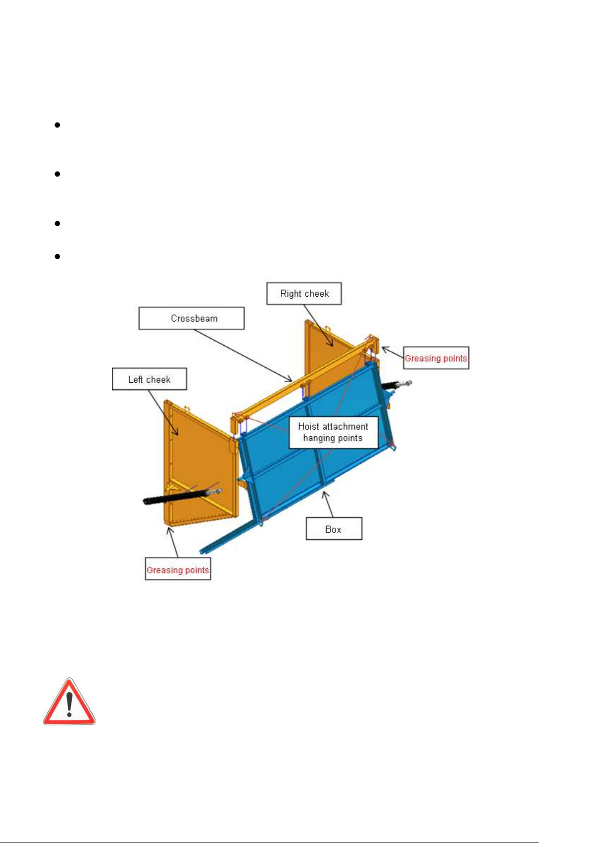
« LOULOU » Hatch
Having lubricated them with grease, assemble the cheeks. Greasing makes assembly
and disassembly easier since settings are adjusted in order to ensure assembly
watertightness. Attach to the spreader box with the screws supplied.
On the ground, assemble the box with the cross section higher using the spindles
supplied Make sure to put the locking pins in position in order to tighten up the
assembled set section.
By means of an overhead bridge crane, a hoist or a loader, put the box set in place with
the crossbeam. Attach to the cheeks with the screws supplied.
Finish by placing the jacks in position, the barrel being on the box side.
All operations carried out at height should be done using a suitable type of scaffolding
which is in compliance with regulations currently in force and set out for this kind of product
(body protectors, etc…).
The hatch opening jack « LOULOU » come equipped with double-pilot
valves. Pay attention to any potential residual pressure that there might be
between the valve and the jack.
Notice originale : Français NT0002 V –p – 03/2014

54
Component
Quantity
Illustration
Suspension jack
2
Suspension block with
tiller fitted with two
membrane accumulators
1
Jib 1
9-APPENDICES
APPENDIX 1
NOTES FOR SUSPENSION USE OF THE HYDRAULIC JIB
1- SYSTEM PRESENTATION
All trailer tillers are classed as hydraulic suspension jibs when they come fitted with
absorption systems which are powered by hydraulic technology rather than by parabolic
springs.
The system is governed by the tractor. The user can correct the height of his tiller trailer
in real time.
2- OPERATING PRINCIPLES
The system mainly comprises the following elements :
The different elements are assembled according to the following outline:
Notice originale : Français NT0002 V –p – 03/2014

55
3- SETTINGS IMPLEMENTATION AND USAGE
The jib should be set in such a way as to keep the trailer in a horizontal position.
It should however rest on the jackpin to deaden powerful bumps ( 3cm)
2 methods of use are envisaged:
It may be that the user wants a predefined trailer height setting valid throughout. In this
case the feed tubes on the circuit are not connecterd to the tractor. It is to be noted thst
the tiller functions in closed circuit , i.e, when the dumper is loaded, it can knock itself
over, and when going spreading, the jacks can be deployed and no corrective action is
possible.
This method of use is strongly advised against, despite the potential
benefits of having a distributor on the tractor.
Should the user leave pipes permanently attached to the tractor, he will thus be able to
alter the tiller height in real time and catch at will any jack oscillation due to any
variation of load in the vehicle.
This is the »normal» use of the system.
Operating this way gives maximum suspension supplety.
N.B : 2 or 3 adjustments are possible at the height attachment jack. The process for
attachment height procedure is the same as for the spring rest (see page 28)
Notice originale : Français NT0002 V –p – 03/2014

56
Compoennt
Quantity
Illustration
Suspension jack
4 suspension jacks for a 2axle vehicle
(6 for a 3-axle vehicle).
Passive suspension block B
1
Nitrogen ballholders
2
APPENDIX 2
USE NOTICE FOR PASSIVE SUSPENSION ON THE
UNDERCARRIAGE (Closed circuit ) ( ROLLMAX option)
1- SYSTEM PRESENTATION
Inactive, or even closed circuit suspension on train undercarriages comes equipped
with an autonomous shock absorption system.
The circuit is completely independent of the tractor.Suspension is regulated once and
for all (whilst still remaining alterable on occasions where necessary).Adjustment is made in
such a way that there is an optimum maximum articulation of the load .A jack stroke being
at 200mm, optimum articulatuion will be about ± 100mm.
The user cannot rectify the height of his vehicle in real time.
2- OPERATING PRINCIPLES
The system mainly comprises the following elements :
4 suspension jacks for a 2-axle vehicle (6 for a 3-axle vehicle)
1 hydraulic suspension management block
2 pistons accumulators
The system mainly comprises the following elements:
Notice originale : Français NT0002 V –p – 03/2014

57
External faucets
Middle
Manonometer
2 remarks :
There is a system in place during assembly intended to counter vehicle roll. Oil will never
just flow to where it is « easiest » Loads will be consistently equal on all 4 wheels, which in
turn provides hopper stability.
The pressure limit gauge is intended to even out abnormal peak pressure demands (violent
powerful bumps).
3- SETTING AND USE RECOMMENDATIONS
a. To increase the height of the suspension (raise the box) :
To add oil to the suspension circuit (if the height is deemed insufficient for example), it
is necessary to go ahead in the following manner :
Passive suspension block :
Attach the pipe marked by a spot to the tractor (the long green one ).
Open the two external block valves (see photo).The middle valve must be closed
Feed the oil circuit via the tube attached to the tractor until the desired level is attained A.
Reclose the two external valves and open the middle valve.
Release the residual pressure present in the pipe, whilst setting the tractor distributor to
"float".
Disconnect the (long green) tractor pipe.
Only the (short green) drain return pipe should remain connected.
ATTENTION: Be aware that spreader height may vary dependent on the
internal load.
Notice originale : Français NT0002 V –p – 03/2014

58
b.To increase the height of the suspension (raise the box):
To remove oil from the suspension circuit (where height is deemed too important for
example), it is necessary to go ahead as follows :
Attach the connector marked by a spot (the long green one) to the tractor.
Open the 2 external block valves (see photo).The middle valve should be closed
Set the relevant tractor distributor to "float" position until the required height is attained.
Reclose the 2 external valves and open the middle valve.
Release the residual pressure present in the pipe, whilst setting the tractor distributor to
"float".
Disconnect the (long green) tractor pipe.
Only the (short green) (vert court) drain return pipe should remain connected.
RECOMMENDATIONS FOR USE :
The tube which serves to regulate the height of the hopper must only be connected in
suspension interventions. In normal operations, this pipe must be attached tto the pipe box
door nose.
On the other hand, the "drain" pipe (oil return in the event of high excess pressure) must
remain permanenetly attached to the tractor.
AXLE OPTIONS BEFORE PRESSURE ABSORPTION (with 3 axles) :
A basic pipe (in a brown sheath like with the load transfer function) allows axle
command before absorption. In normal operating conditions (3-axle suspension), it is vital to
set the tractor distributor to "float".
This option is not recommended for 2-axle vehicles since it is incompatible with rear
steering axles. The combination of these two options would lead to vehicle instability.
Notice originale : Français NT0002 V –p – 03/2014

59
Date
Operation
Remarks
Visa
- Check wheel tightness
Every 50 km then twice yearly or at
he beginning of each season
- Check tyre inflation
pressure
Twice a year or at the beginning of
each season.
- Check for axle tightness or
the axle fulcrum
Twice a year or at the beginning of
each season.
- Grease points indicated in
the handbook
Check before each use
Actions to be carried out
prior to use by the
repurchaser
- Check for proper service
brake tightness, for
breakages and stationary
positioning
Make up for any defects found as
necessary
Operations to carry out before start-up
(by the DEALER)
9- Maintenance Log
Notice originale : Français NT0002 V –p – 03/2014

60
Date
Operation
Remarks
Maintenance Log
Notice originale : Français NT0002 V –p – 03/2014

61
11- CE Conformity Declaration for machines
(According to Annex IIA of Machines Directive 2006/42/CE)
Manufacturer: Ets ROLLAND
Address: Z.A des Landes 29800 TREFLEVENEZ
Name and address of the person authorised to elaborate technical dossier:
Name : Béatrice LE GALL
Address : Z.A des Landes 29800 TREFLEVENEZ
Through this document, we declare that
The machine:
- Brand: ROLLAND
- Commercial Designation:
- Type:
- Serial Number:
is in accordance with the relevant disposals of Machines Directives (2006/42/CE).
In addition, we declare that
(parts / articles ) compliant with the following European standardised standards were
applied.
-EN ISO 12100-1 & 12100-2
Done at TREFLEVENEZ, on
Name and title of signatory
Béatrice LE GALL
General Director
Notice originale : Français NT0002 V –p – 03/2014

62
12- WARRANTY CERTIFICATE – DECLARATION OF
START-UP OPERATION
Examples in this instance
USER
Name : ………………………………………………………………………………………………….
Address : ………………………………………………………………………………………………
Post Code : …………………City: …………………………..Country………………………………..
Landline : ……………………………… Mobile …………………………………
Fax : ………………………… Email : ……………………………………………………………….
VEHICLE
Type of vehicle : …………………………………………………………………….………………
Series N° (on the invoice or on the disc plate) : ………………………………………………….
Purchase date : ………………………………………………………………………………………….
Delivery date : …………………………………………………………………….……………….
GUARANTEE
Our vehicles are guaranteed for one year starting from the delivery date.Conditions of use are stipulated in the
service handbook which accompanies the vehicle. The prescribed conditions of use must be respected at all
times, where this isn’t the case then the guarantee will be rendered invalid. Movement and transport are not
included in the guarantee. Only fully purchased vehicles may benefit from the guarantee.In ther event of
difficulties the user should contact the dealer in the first instance.
I acknowledge that I am aware of the service terms and conditions and undertake to respect the
terms and conditions contained herein in order to take advantage of the one year guarantee
Name and signature of service person responsible : User signature :
Notice originale : Français NT0002 V –p – 03/2014

63
YOUR VIEWS COUNT
For the purposes of continuous improvement, please reply to the questions below : (tick your choice)
Compliance with delivery terms Good Average Bad
Delivery quality
First impressions of vehicle
Start-up quality
Your decision was based on : ( 3 possible choices on descending scale 1-3, 1 being your first choice)
Good price to quality ratio
Product design
Delivery time
Brand reputation
Brand quality
Brand trustworthiness
Your comments……………………..
Notice originale : Français NT0002 V –p – 03/2014
 Loading...