

Roline LineSecure 600VA, LineSecure 800VA, LineSecure 1500VA, LineSecure 1000VA User Manual
Page 1

Lineinteraktive USV
mit Sinus Ausgang
LineSecure
600VA/ 800VA/1000VA/ 1500VA
Bedienungsanleitung
Seite 1 von 44
SECOMP Electronic Components GmbH
Einsteinstrasse 17-23
D-76275 Ettlingen
Page 2

Vertrieb in Deutschland über :
SECOMP GmbH
Einsteinstr. 17 – 23
D-76275 Ettlingen
Tel. 07243 – 383 111
Fax 07243 – 383 222
Vente en France par :
SECOMP France S.N.C.
„Les Espaces Multiservices“
Lot 43
56, Bd. de Courcerin
F-77183 Croissy Beaubourg
Tel. 0033 16-4809230
Fax 0033 16-4809240
Distributor in United Kingdom:
Rotronic Interconnections Ltd.
Rotronic House
Vector Point, Newton Road
Crawley, W.Sussex RH10 2TU
Tel. 0044- 12-93565556
Fax 0044- 12-93843710
All other Countries:
Rotronic AG
Grindelstr. 6
CH-8303 Bassersdorf
Tel. 0041- 1- 8381111
Fax 0041-1-8381360
LineSecure 11.04.02 Alle Rechte vorbehalten. Änderungen vorbehalten.
Seite 2 von 44
SECOMP Electronic Components GmbH
Einsteinstrasse 17-23
D-76275 Ettlingen
Page 3

Lieferumfang der LineSecure Anlagen
USV mit Batteriesatz
Serielles Verbindungskabel
Telefon/Modem Kabel (RJ12)
Netzkabel
Apparateverbindungskabel
Software CD ( deutsch ) Windows 95 / 98 und Novell ( Einzelplatzversion )
Deutsche Anleitung für Software auf CD
Techn. Handbuch deutsch
Seite 3 von 44
SECOMP Electronic Components GmbH
Einsteinstrasse 17-23
D-76275 Ettlingen
Page 4

1. Einführung
Es handelt sich hier um eine lineinteraktive USV nach
IEC 62040-3; EN 50091-3 Klassifikation VI-SS-311
mit leistungsstarken Funktionen und modernster Technologie.
Diese USV mit AVR Funktion regelt die Eingangsspannung zwischen 75% und 125 % mit Spannungssenkung
bzw. Spannnungserhöhung . Sie schützt angeschlossene Geräte auf ideale Weise. Die Steuerung durch einen
Mikroprozessor ermöglicht auch ein Laden des Akkus bereits beim Anschluss der USV an die Netzspannung
ohne dass diese eingeschaltet sein muss. Im Back-UP Modus kann sich die USV zur Batterieschonung
automatisch Ausschalten, wenn keines der angeschlossenenen Geräte in Betrieb ist. Eine Akkuwechselanzeige
ist ebenso integriert wie ein zyklischer Selbstest für die USV und die Batterie.
Auf der Rückseite ist zum Schutz vor Überspannungen auf Telefon oder Modemleitungen ein RJ12 Anschluss
vorhanden.
Die mitgelieferte Software erlaubt über die eingebaute serielle Schnittstelle eine perfekte Überwachung und
Steuerung des angeschlossenen Rechner’s und sonstiger kritischer Geräte.
2. Sicherheitshinweise
- Diese Anleitung enthält wichtige Sicherheitshinweise die während der Installation und Wartung der USV
eingehalten werden müssen .
Vorsicht: Bitte beachten Sie die Sicherheit und Leistung der USV, schließen Sie keinen Föhn, Heizung,
Laserdrucker oder andere induktive Lasten an.
- Die USV erzeugt gefährliche elektrische Spannungen im Inneren. Alle Wartungsarbeiten dürfen
ausschließlich nur von entsprechendem Fachpersonal ausgeführt werden.
- Die USV enthält Batterien. Die Ausgangssteckdosen könnten unter Spannung stehen, auch wenn das Gerät
nicht an das Stromnetz angeschlossen ist.
- Während des Gebrauches muß die USV Anlage geerdet sein. Die grüne oder gelb-grüne Leitung muß
angeschlossen sein. Ziehen Sie nicht den Stecker während des Betriebes der USV Anlage. Damit würde die
Erdverbindung von der USV Anlage und allen angeschlossenen Verbrauchern unterbrochen.
- Das Erdungskabel muß immer angeschlossen sein. ( sowohl im Anschlußstecker wie auch in der
Netzanschlußdose )
- Um die Sicherheitsfunktion und Funktionsweise aufrecht zu erhalten, muß die USV richtig installiert sein.
- Das Gerät darf nicht unnötig geöffnet werden.
- Die USV darf nur über einen 3 poligen Schutzkontaktstecker und 3 Leitungen angeschlossen werden.
- Die USV darf nicht in feuchter Umgebung eingesetzt werden.
- Es dürfen weder Flüssigkeiten noch Gegenstände in die USV gelangen.
- Um die USV muß die Luft zirkulieren können.
- Die USV sollte vor direkter Sonneneinstrahlung und Hitzeeinwirkung geschützt werden.
- Die USV sollte in der Nähe des Verbrauchers stehen.
Achtung: Hochspannung !
- Falls die Batterie nicht von der Elektronik abgeklemmt ist, liegt zwischen der Batteriezuleitung und Masse
des Systems lebensgefährliche Spannung an. Bitte kontrollieren Sie die Spannung bevor Sie verbinden.
- Bevor mit der Wartung begonnen wird müssen die Batteriezuleitungen unterbrochen werden. Auch wenn
die USV nicht mit dem Stromnetz verbunden ist, besteht ein potentielles Risiko durch hohe Spannungen
zwischen den internen Komponenten der USV und den Batterien.
Seite 4 von 44
SECOMP Electronic Components GmbH
Einsteinstrasse 17-23
D-76275 Ettlingen
Page 5

3. Bedienelemente, Anzeigen und Anschlüsse
Vorderseite
3.1 Taste „EIN/TEST“
Bei bestehender Netzverbindung , wird die USV und die angeschlossene Last durch Drücken dieser Taste
eingeschaltet. Auch der Selbsttest wird durch Tastendruck gestartet.
3.2 Anzeige „Überlastung“ ( rote LED )
Wenn die gesamte angeschlossene Last die Leistung der USV übersteigt, leuchtet diese rote Anzeige.
3.3 Anzeige „Back Up Mode“ ( grüne LED )
Diese grüne LED leuchtet bei Stromausfall, wenn die angeschlossene Last durch den eingebauten Akku
versorgt wird.
3.4 Anzeige „Batteriewechsel“ ( rote LED )
leuchtet, wenn die eingebaute Batterie nicht mehr genügend Kapazität hat, um die angeschlossene Last
ausreichend abzusichern.
3.5 Anzeige „AVR Senkung“ ( gelbe LED )
Falls die Netzeingangsspannung zu hoch wird, leuchtet diese Anzeige und die Last wird mit normaler
Netzspannung versorgt.
3.6 Anzeige „Netzspannung“ ( grüne LED )
Wenn die Netzeingangsspannung anliegt, leuchtet diese LED.
3.7 Anzeige „ AVR Anhebung “ ( gelbe LED )
Falls die Netzeingangsspannung zu niedrig wird, leuchtet diese Anzeige und die Last wird mit normaler
Netzspannung versorgt.
3.8 Anzeige „ Belastung “
Mit dieser Bargraph LED Anzeige wird die angeschlossene Belastung angezeigt.
3.9 Anzeige „ Ladezustand der Batterie “
Mit dieser Bargraph LED Anzeige wird der Batterieladezustand angezeigt.
3.10 Taste „ AUS “
Durch drücken dieser Taste werden die USV und die angeschlossenen Geräte ausgeschaltet.
Seite 5 von 44
SECOMP Electronic Components GmbH
Einsteinstrasse 17-23
D-76275 Ettlingen
Page 6

Vorderseite
3.11
3.12
3.13
Rückseite
3.15
3.16
3.14
Seite 6 von 44
SECOMP Electronic Components GmbH
Einsteinstrasse 17-23
D-76275 Ettlingen
Page 7

Rückseite
3.11 Telefon / Modem Überlastungsschutz
Es handelt sich hier um einen Überlastungsschutz für Telefon und Modem, so dass Sie über
eine rundum sichere Internet Verbindung verfügen.
3.12 Stromausgänge
3.13 Netzstromeingang
3.14 Hauptsicherung
Wenn die angeschlossene Last die zulässige Gesamtlast der USV übersteigt, wird diese Sicherung
ausgelöst. Zur Wiederinbetriebnahme die mittlere Drucktaste betätigen.
3.15 Anzeige für falsche Verkabelung ( rote LED )
Diese Anzeige leuchtet, wenn die Steckdose an der die USV angeschlossen wurde, falsch verdrahtet ist.
3.16 PC Schnittstelle
Serielles Interface und Relaiskontaktausgang zur Unterstützung aller gängigen Betriebssysteme.
4. Installation
4.0 USV prüfen
Überprüfen Sie den Packungsinhalt der USV an Hand der Liste „ Lieferumfang“ ( 2.Seite)
4.1 Aufstellen der USV
Die USV darf nur in einem staubfreien und geschützten Raum mit geeigneter Belüftung installiert und in
Betrieb genommen werden. Die entsprechenden Grenzwerte finden Sie hinten in der Tabelle mit den
technischen Daten.
4.2 Verbindung mit dem Computer
Über die eingebaute serielle Schnittstelle und mit der mitgelieferten Software lässt sich ein Rechner steuern.
Schliessen sie das mitgelieferte 9 pol. Kabel an die Schnittstelle der USV und an Ihren Rechner an. Verwenden
Sie bitte nur das mitgelieferte Kabel. Die USV arbeitet auch ohne eine Verbindung über die
Schnittstelle mit der Last, und ohne Software, nur kann dann die Last weder gezielt gesteuert noch überwacht
werden.
4.3 Telefon/Modemkabel anschliessen
Verbinden Sie Ihre Telefon/Modemleitung mit dem mitgelieferten RJ12 Kabel auf der Rückseite der USV und
Sie erhalten einen wirksamen Überspannungsschutz für Ihre Kommunikationsanschlüsse.
Wichtig: Bei falschem Anschluss kann der Überspannungsschutz funktionslos werden. Prüfen Sie, ob die von
der Wanddose kommende Leitung mit „EIN“ und das zu schützende Gerät mit „AUS“ verbunden ist.
4.4 Netzanschluss der USV
Schliessen Sie die USV mit dem Netzkabel an das Stromnetz an.
Seite 7 von 44
SECOMP Electronic Components GmbH
Einsteinstrasse 17-23
D-76275 Ettlingen
Page 8

4.5 Akku Laden
Wenn die USV Netzverbindung hat, wird der Akku geladen.
Bei der ersten Inbetriebnahme müssen die Batterien min. 8 Stunden geladen werden
4.6 Geräte anschliessen
Schliessen Sie die Geräte an die entsprechenden Anschlüsse auf der Rückseite an. Um die USV als
Hauptschalter zu nutzen, müssen alle angeschlossenen Geräte eingeschaltet sein.
4.7 Anzeige für falsche Verkabelung prüfen
Nach dem Anschluss der Geräte und der USV, ist die Anzeige für falsche Verkabelung auf der Rückseite zu
prüfen. Leuchtet die Anzeige, ist die USV an eine falsch verkabelte Steckdose angeschlossen. Erkannte
Verkabelungsfehler sind Schutzleiter, Nulleiter, Beschaltung und Überlast.
5. Betrieb
5.1 Einschalten
Wenn die USV mit der Netzspannung verbunden ist, drücken Sie die Taste „EIN/TEST“ für 1 Sekunde.
Nach jedem Einschalten wird ein Selbsttest durchgeführt.
Hinweis: bei ausgeschalteter USV wird der Akku geladen und die USV ist über die serielle Schnittstelle
zu steuern.
5.2 Ausschalten
Drücken Sie die Taste „AUS“ , bis die LED’s „Netzspannung“ bzw. „Back Up Mode“ ausgehen.
5.3 Selbsttest
Beim Selbsttest wird die USV und der Akku überprüft. Drücken Sie bei normaler Netzspannung die Taste
„EIN/TEST“ min. eine Sekunde. Während des Eigentests schaltet sich die USV kurz in den Back Up Mode.
Wird der Selbsttest erfolgreich abgeschlossen kehrt die USV zum Normalbetrieb zurück und die Betriebsanzeige leuchtet wieder. Bei einem Fehler wird ebenfalls der Normalbetrieb wieder aufgenommen, zusätzlich
Leuchtet aber die Batteriewechsel LED. Laden Sie über Nacht den Akku auf und führen Sie erneut den
Selbsttest durch. Bei gleicher Fehlermeldung setzen Sie sich mit Ihrem Händler in Verbindung.
5.4 Alarmton abschalten
Drücken Sie im Back Up Mode die Taste „EIN/TEST“ länger als 1 Sekunde, um den Alarm auszuschalten.
Dies funktioniert nicht, wenn die Batterie leer ist, oder bei Überlastung.
5.5 Laststatus anzeigen
Diese Bargraph Anzeige zeigt die aktuelle Belastung der USV durch die angeschlossenen Geräte an. Bei
Übelastung leuchtet die entsprechende LED und es ertönt ein Alarmton.
5.6 Akkuladung anzeigen
Diese Bargraph Anzeige zeigt die aktuelle Ladekapazität der Akkus an. Leuchten alle fünf LED’s sind
die Akku’s voll aufgeladen. Blinkt die unterste LED, hält die Überbrückung nur noch für ca. 2 Min.
Seite 8 von 44
SECOMP Electronic Components GmbH
Einsteinstrasse 17-23
D-76275 Ettlingen
Page 9

5.7 Kaltstart
Bei ausgeschalteter USV und fehlender Netzspannung kann die angeschlossene Last über die eingebauten
Batterien versorgt werden. Dazu drücken Sie bitte die Taste „EIN/TEST“ solange, bis die USV piepst.
5.8. Abschaltmodus
Im Abschaltmodus unterbricht die USV die Energieversorgung zur Last solange, bis die Netzspannung
wiederkehrt. Über die serielle Schnittstelle kann ebenfalls ein Ausschalten der USV gesteuert werden.
Im Abschaltmodus lässt die USV die Anzeigen an der Vorderseite kurz aufleuchten.
6. Alarmsignale
6.1 „ Back Up Mode “ (langsamer Piepton)
In diesem Modus leuchtet die gelbe LED und die USV erzeugt langsame Pieptöne. Dies endet erst,
wenn die USV zum normalen Betrieb zurückgekehrt ist. Durch Druck auf die Taste „EIN/TEST“
kann der Alarmton ausgeschaltet werden.
6.2 „ Batterie schwach“ (kurze Pieptöne im Intervall)
Geht im Back Up Mode die Batteriekapazität zu Ende, erzeugt die USV solange schnelle Pieptöne, bis
Sich die USV wegen mangelnder Überbrückungszeit abschaltet, oder zum Normalbetrieb zurückkehrt.
6.4 „ Akkuwechsel “ (Daueralarm)
Besteht der Akku nicht den Selbsttest, folgt ein Daueralarm und die LED für den Akkuwechsel leuchtet.
Der Akkutausch wird wie im Abschnitt 10 beschrieben, durchgeführt.
7. Computer Interfaceanschluss
Dieser Kommunikationsanschluss an der Rückseite der USV dient zur Verbindung mit einem Computer.
Über diesen Anschluss lässt sich der Status der USV überwachen und teilweise steuern. Die Hauptmerkmale
bestehen aus folgenden Funktionen:
- Ausgabe eines Warnsignals bei Stromausfall
- Schliessen aller geöffneten Dateien, vor völliger Akkuentladung
- Ausschalten der USV
Die 9 polige D-Sub Buchse ist wie folgt belegt:
1. Pin 5 und 2 sind offene Kollektorausgänge für max 40 V Gleichspannung und dürfen nur mit max.25 mA
Gleichstrom belastet werden.
2. Pin 4 ist Masse
3. Pin 5 erzeugt ein Hi/Lo Signal, wenn die Akkuladung nur noch für 5 Minuten Überbrückung ausreicht.
4. Pin 2 erzeugt ein Hi/Lo Signal wenn die Netzspannung ausfällt.
5. Die USV schaltet sich ab, wenn Pin 1 für 0,36 Sekunden einen Hi Pegel nach RS232 erhält
6. Pin 9 ist die Sendeleitung TxD
7. Pin 6 ist die Empfangsleitung RxD
Bitte benutzen Sie nur das original USV Verbindungskabel, das jeder USV beiliegt.
8. Akkuwechsel
Die Nutzungsdauer des Akku’s beträgt etwa 3 – 5 Jahre, bevor er ausgetauscht werden muss. Um den
Akkuwechsel problemlos durchführen zu können, beachten Sie bitte die folgenden Anweisungen :
Seite 9 von 44
SECOMP Electronic Components GmbH
Einsteinstrasse 17-23
D-76275 Ettlingen
Page 10

1. Entfernen Sie alle Steckverbindungen zur USV ( Netzkabel, Telefonkabel, Serielles Kabel )
2. Nehmen Sie die Front der USV ab indem Sie die Front nach vorne abklappen, lösen Sie die Schrauben
und klappen Sie das Blech nach vorne ab. Ziehen Sie die Batterien aus der USV heraus und entFernen Sie das Batteriekabel. Der Einbau folgt in umgekehrter Reihenfolge.
3. Nun können alle externen Kabel wieder angeschlossen werden.
9. Fehlerbehebung
Fehler Ursache Fehlerbehebung
USV lässt sich Taste EIN/TEST nicht Schalten Sie die USV und Ihre Geräte
nicht einschalten oder zu kurz gedrückt durch drücken der Taste EIN/TEST ein
Hauptsicherung aktiviert Verringern Sie die angeschlossene Last
und schalten Sie die Hauptsicherung
wieder ein
Niedrige oder keine Prüfen Sie die Netzspannung
Netzspannung
USV lässt sich nicht Schnittstelle fehlerhaft Entfernen Sie das Schnittstellenkabel.
Ein- oder ausschalten Taste EIN/TEST nicht Funktioniert die USV normal, prüfen
oder zu kurz gedrückt Sie das Interfacekabel, den Computer
und die angeschlossene Last
USV verbraucht Akku- Hauptsicherung aktiviert Verringern Sie die angeschlossene Last
Strom bei normaler und schalten Sie die Hauptsicherung
Netzspannung wieder ein
Gelegentlich erzeugt normaler USV Betrieb Normalzustand
die USV Pieptöne
USV hat zu kurze Akku entladen oder nicht Laden Sie den Akku. Falls dieser nicht
Überbrückungszeit mehr zu laden mehr geladen werden kann, ist der Akku
zu wechseln.
die USV ist überlastet Prüfen Sie die Lastanzeige, verringern
Sie die Last
Anzeigen an der Front USV ist per Schnittstelle Keine. Die USV startet automatisch
blinken nacheinander abgeschaltet worden nach Netzwiederkehr
Alle Anzeigen blinken interner USV Fehler USV sofort ausser Betrieb nehmen,
und ein Alarm ertönt kontaktieren Sie Ihren Händler
USV arbeitet normal, Verkabelungsfehler an der Ihre elektrische Verkabelung muss
aber die Anzeige für Steckdose oder im Gebäude von einem qualifiziertem Elektriker
falsche Verkabelung überprüft werden
leuchtet
Anzeige für schwache USV hat abgeschaltet und Keine. Bei Netzwiederkehr schaltet
Batterie leuchtet der Akku ist leer oder nicht sich die USV wieder in den Normalbetrieb,
Mehr zu laden bzw. wenn der Akku wieder voll ist
Die Akkuwechsel- schwacher Akku Akku min. 4 Stunden laden. Bei bestehendem
anzeige leuchtet Fehler ist der Akku zu wechseln
Seite 10 von 44
SECOMP Electronic Components GmbH
Einsteinstrasse 17-23
D-76275 Ettlingen
Page 11

Technische Daten LineSecure
Schein
Leistung VA
Wirk
Leistung W
Ausführung Stand Stand Stand/RM Stand/RM
Eingangs
Spannung
Frequenz 50/60Hz
Phase 1ph
Batterie Überbrückungszeit
100% Last
50% Last 23 Min. 15 Min. 10 Min. 7Min.
Wiederaufladezeit 4h zu 90%
Austausch im Betrieb wechselbar
Ausgang Frequenz 50/60Hz, Sinus
Spannungsregulierung Buck u. Boost
Frequenzstabilität +-0,5%
Leistungsfaktor 0,7
Überlasterkennung 110%-20sec.
Filter Überspannung 320 Joule, 2msec.
Eingang Überlast u. Kurzschluss
EMI/RFI 10 dB bei 0,15 Mhz, 50 dB bei 30 MHz
Transfer Umschaltzeit 2-4 msec
PF=0.7 600 800 1000 1500
PF=1.0 420 560 700 1050
172-287 V AC
9 Min. 5 Min. 3 Min. 3 Min.
Lärmpegel 1m Entfernung < 40 dBA < 50 dBA
Umgebungsbed. Temperatur 0-40°C
Luftfeuchtigkeit 0-95% nicht kond.
Komm.
Schnittstelle
Grösse BxTxH Standgehäuse 140x445x200 170x448x214
Gewicht (netto) 13,8 kg 14,5 kg 15,0 kg 28,0 kg
Grösse BxTxH Rackgehäuse 483x381x84
Gewicht (netto) 20 kg 25 kg
RS232 + potentialfreie Kontakte
(2HE)
483x381x130
(3HE)
Seite 11 von 44
SECOMP Electronic Components GmbH
Einsteinstrasse 17-23
D-76275 Ettlingen
Page 12

Lineinteractive UPS
Pure Sine Wave Output
LineSecure
600VA/ 800VA/1000VA/ 1500VA
User’s Manual
Seite 12 von 44
SECOMP Electronic Components GmbH
Einsteinstrasse 17-23
D-76275 Ettlingen
Page 13

Package contents
UPS with Battery Set
Serial cable
Telephone / Modem cable (FJ12)
Mains cable
Load Power Cable (IEC 320)
Software CD (English) Windows 95/98 NT 2000 XP and Novell (Single User Version)
Technical Handbook
Seite 13 von 44
SECOMP Electronic Components GmbH
Einsteinstrasse 17-23
D-76275 Ettlingen
Page 14

1. Introduction
The UPS corresponds to the new classification
IEC 62040-3; EN 50091-3 classification VI-SS-311
This interactive UPS offers strong performance advantages with state of the art technology. Through the AVR
(Automatic Voltage Regulation) the battery is continuously and gently charged. The AVR regulates electrical
input within the range of 75% to 125% insuring the optimal conditions for effective battery charging. This
system manages itself using a onboard microprocessor. The system begins charging its batty as soon as it is
connected to the building mains. There is no need to insure the UPS is switched on for the battery to begin
charging. The system automatically monitors it loads and shuts down when zero load is detected. The UPS
offers a Change Battery Display and a cyclic self test.
The UPS offers surge protection for telephone lines. On the rear panel of the machine are sockets for telephone
or modems.
The included software allows easy management over a serial cable.
2. Safety Precautions
- Please be sure to consult this handbook during the installation of you UPS. Very Important: never
attach a hairdryer, heater, laser printer or any other inductive electrical device to you UPS!
- This device should only be served by qualified personal. Danger of electrical shock if opened!
- The batteries contained within this device are electrically charged and even when not connected to the
mains there is a danger of electrical shock.
- The UPS must be grounded during use. The green or yellow/green cable must be grounded to insure
safe performance. Never remove the plug from the mains during use, otherwise the UPS itself and the
loads are not grounded.
- The green or yellow/green cable must always be grounded. (The mains plug and the load sockets must
be grounded.)
- To maintain the safety functions of the UPS proper installation is absolutely necessary!
- This device should not be unnecessarily opened.
- Use only 3 pole plug and maximal 3 cables to attach this device to electricity.
- The UPS should be used in a cool dry place.
- No foreign objects or water should reach the inside of the device.
- Ensure adequate air circulation for the device.
- Do not place device in direct sunlight or near heaters.
- Attempt the place the UPS as close to the loads as possible. The length of the cables can influence its
performance.
Caution! High Voltage Danger!
- Danger of high voltage!! Always insure the battery is completely disconnected before attaching
additional battery packs to the UPS. There is dangerously high electrical tension between the battery
and the chassis.
- A shock could be deadly! Please test the system for electrical tension before connecting any new
battery packs.
- Before you open this device to replace battery packs or maintenance in general make sure that the
battery packs are completely disconnected from the electronic of UPS. Although the UPS is from the
electrical socket disconnected there are still high tensions within the device itself.
Seite 14 von 44
SECOMP Electronic Components GmbH
Einsteinstrasse 17-23
D-76275 Ettlingen
Page 15

3. User Controls and Presentation
Front Panel of UPS
3.1 Button On/Test
This button tuns on the UPS. The UPS functions only when the input voltage correctly connected is and
there are dependent units attached to it. This button also activates the self test mode of the UPS.
3.2 Overload Indicator (red LED)
This LED indicates that the UPS is overloaded. This occurs when to many loads are attached to UPS
.
3.3 Back Up Mode Indicator (green LED)
This LED indicates a power failure during which the loads are being powered by the UPS battery.
3.4 Change Battery Pack (red LED)
This LED indicates that new a new battery is necessary. The UPS has detected that the battery cannot
store enough electricity to supply the load incase of power failure.
3.5 Buck AVR (Voltage Reduction) (yellow LED)
The UPS has detected an input over voltage situation. The systems AVR is internally reducing the
voltage to within a normal voltage range. (220-230v) The loads receive normal voltage.
3.6 Line Voltage (green LED)
Indicates that the UPS is connected to the buildings mains.
3.7 Boost AVR (Voltage Increasing) (yellow LED)
The UPS has detected an input under voltage situation. The AVR is internally increasing the voltage to
within a normal range. The loads receive normal voltage.
3.8 Load Bar Graph
Indicates the present load situation of the UPS.
3.9 Power Bar Graph (Battery Charge/Line Charge)
Indicates the present level of battery charge in percentage to a full charge.
3.10 Off Button
Completely shuts down the UPS and its loads.
Seite 15 von 44
SECOMP Electronic Components GmbH
Einsteinstrasse 17-23
D-76275 Ettlingen
Page 16

Front
Rear
3.11
3.12
3.13
3.15
3.16
3.14
Seite 16 von 44
SECOMP Electronic Components GmbH
Einsteinstrasse 17-23
D-76275 Ettlingen
Page 17

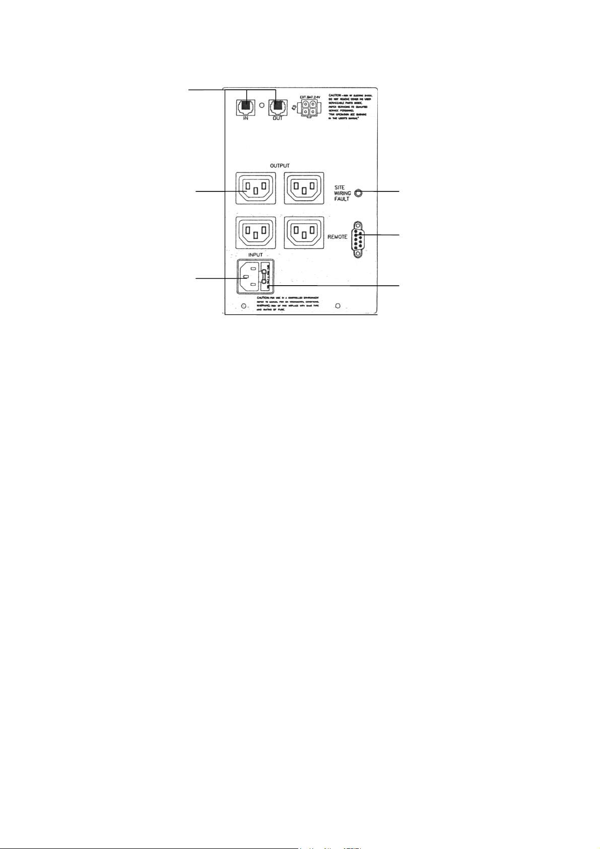
Rear Panel of UPS
3.11 Telephone Line or Modem Surge Protection
Protects against power surges that can come over the telephone line. This connection offers ideal
protection against power surges which could occur while connected to the Internet over a modem.
3.12 Output Power Receptacles
3.13 AC Input Power Receptacles
3.14 Input Circuit Breaker
This breaker trips when the connected load exceeds the maximal limit of the output receptacles. A
plunger exceeds from the center of the breaker when it trips. In order to reactivate the circuit breaker
simply push in the plunger.
3.15 Building Mains Wiring Fault Indicators (Red LED)
Indicates that the UPS is connected to a improperly wired AC outlet.
3.16 Computer Interface
The interface provides both RS-232 interface(serial) and offers a relay signal. It offers support for
Novell, Unix, DOS, Windows and other operating systems.
4 Installation
4.0 Inspection of UPS
Insure that the contents are complete. (using the list provided on page 2) The packaging material is
recyclable. We recommend that you keep the packaging for eventual use in the future.
4.1 Proper Placement of UPS
The UPS should be placed in a protected, ventilated and dust free area. Insure operation of the UPS
within the specified temperature and humidity range.
4.2 Connecting the UPS to PC
The UPS has s serial port on the rear panel. Connect the UPS to the computer over this port using the
factory supplied 9 pin serial cable. The UPS operates without being connected to the PC, but the
management features are not available.
4.3 Connecting the Modem/Telephone Lines
Using the Rj-45/RJ-11 sockets found on the rear panel of the UPS you can protect a single line
telephone or modem against power surges.
IMPORTANT NOTE: The surge protection for the telephone lines can be rendered inoperable if
the cables are not properly connected! Please insure that the telephone cable leading from the
wall is connected to the “IN” socket of the UPS and the one leading to telephone/modem
connected to the “OUT” socket!! Very Important!!
This UPS is intended for indoor use only! Never attach the telephone cables during a thunder
storm.
Seite 17 von 44
SECOMP Electronic Components GmbH
Einsteinstrasse 17-23
D-76275 Ettlingen
Page 18

4.4 Connecting the UPS to the Input Voltage
Connect the UPS to the building mains using the factory delivered power cord.
4.5 Charging the Battery
As soon as the UPS is attached the building mains it automatically begins charging its battery.
This UPS must be initially connected to the power outlet at least 8 hs, before switching on the load !
Switching on the UPS
After the battery is charged attach your required loads UPS. Pushing the ON/TEST button quickly (less
then a second) will turn on the UPS. The UPS performs a self test every time its turned on.
CAUTION: Never attach a laser printer or a plotter to the UPS!!!!! These devices have warm up
phases which can rashly overload the system. Such overloads can cause severe damage to you
UPS (which may or may not be covered by the warranty!). Due the high voltage components built
within the UPS and the danger of battery explosion or discharge, overloading the system in this
matter could also result in severe or deadly injury.
4.6 Checking the Building Mains Wiring Fault Indicator
After attaching the loads to your UPS, please check the wiring fault indicator on the rear panel. If this
LED lights red there is a problem. The most common faults are: improper grounding, hot-neutral
polarity reversal and overloaded neutral circuit of the AC outlet.
5 Operation
5.1 Switching on the UPS
After connection to the building mains the UPS is turned on by shortly pressing the ON/TEST button.
During the quick self test the UPS goes into Back Up Mode. Afterwards the UPS returns to normal
operation mode.
Note: When not in operation mode the UPS will still respond to commands received form a PC. The
batteries retain their charge.
5.2 Switching off the UPS
The UPS is switched off by pressing and holding the OFF button until the LINE NORMAL or
BACKUP LED ceases to shine.
5.3 Self Test
To initiate a self test press and hold the ON/TEST button for one second. The UPS goes into Back Up
Mode. The On-Battery LED lights up during the test. Upon successfully completing the self test the
UPS returns to Online Mode and the On-Battery LED goes out. If the LED does not go out and the
Change Battery LED blinks, the UPS has a battery failure. In this case the UPS also returns to operation
mode and supplies the loads with electricity as in a normal situation. We recommend the battery be
charged over night and then a second self test be initiated. If this failure persists consult your closest
dealer.
5.4 Turning off the Alarm
Seite 18 von 44
SECOMP Electronic Components GmbH
Einsteinstrasse 17-23
D-76275 Ettlingen
Page 19

If the alarm is sounding press and hold the ON/TEST button longer than a second while in Back Up
mode and it should quiet. This function is void when the batteries are low or the system is overloaded.
(Check system LED’s!)
Note: The system automatically shuts down in Back Up Mode when none of the loads are drawing
electricity.
5.5 Load Bar Graph
Indicates what percent of the UPSs max capacity is being exhausted by the connected loads.
5.6 Battery Charge Bar Graph
Indicates the present state of the battery charging. This is shown in percentage to the maximal charging
capacity. All 5 LED’s will shine when the batteries are fully charged. If the very last LED blinks there
are 2 minutes remaining until the batteries are empty.
5.7 Cold Start
It is possible to operate the UPS, while under load, when it’s disconnected from the buildings mains.
Press and hold the ON/TEST button until a peep ton is heard to activate this feature.
5.8 Shutdown Mode
During a power failure the UPS carefully boots down the attached loads, (PC’s Servers ect) so that no
data is lost. Afterwards the UPS shuts down completely. The UPS remains in this mode until it is
supplied with power again from the buildings mains. The LED’s should shortly flicker in this mode. A
shut down can also be initiated per computer connected to the UPS. (serial port)
6. Alarm Signals
6.1 Back Up Mode (slow peep ton)
The yellow LED illuminates and an audible alarm is activated. These alarm signals will cease when the
UPS can return to the LINE NORMAL condition. The audible alarm can be extinguished by pressing
the EIN/TEST button.
6.2 Low Battery (rapid peep ton)
This alarm indicates that the UPS is in back up mode and the battery capacity is very low. This audible
signal will continue until the batteries are fully exhausted or the UPS can return to LINE NORMAL
condition.
6.3 Overload (persistent peep ton)
When the load being supplied from UPS exceeds its capacity a persistent audible alarm ton is emitted.
Unnecessary loads must be disconnected before the UPS can return to LINE NORMAL condition.
6.4 Replace Battery (persistent peep ton)
The battery must be replaced when the REPLACE BATTERY LED is illuminated, a self test results in
failure and a persistent peeps ton is emitted.
7.0 The UPS has a communication port on the rear panel. This offers limited management of some features
of the UPS. Allows monitoring of the UPS from a satellite computer. Below are the main functions
listed.
Seite 19 von 44
SECOMP Electronic Components GmbH
Einsteinstrasse 17-23
D-76275 Ettlingen
Page 20

1. Transmission of warn signals by power failure
2. Allows the secure closing of all files open before the battery is fully exhausted
3. Shutting down the UPS
Note: Some older computers may need special hardware or software in order to utilize this feature of
the UPS. Ask your local dealer for details.
8.0 Battery replacement
After 3 to 5 years of operation the battery should be replaced.
Please follow the instructions below for easy battery replacement.
1. Unplug unit from AC power source and disconnect all connected equipment.
2. Disconnect AC power cord from unit.
3. Remove the front cover by pulling the front cover from the unit away, unscrew the 2 screws
holding the metal plate and clap it down.
4. Remove the 2 connecting wires from battery
2. You can now easily remove the battery from the unit and replace it with a new one
3. Please follow manual instructions in order to properly reconnect your equipment
Seite 20 von 44
SECOMP Electronic Components GmbH
Einsteinstrasse 17-23
D-76275 Ettlingen
Page 21

9.0 Troubleshooting
Problem Possible Action to take
UPS will not turn on On/test button not Press the on/test button to power the ups
Pushed or push too short and the load
UPS input circuit breaker tripped Reduce the load on the UPS by
unplugging equipment and reset the
circuit breaker by pressing the plunger
back
very low or no utility voltage Check the AC power supply to the UPS
UPS will not turn on/off Computer interface of accessory Disconnect the computer interface or
problem . Push on/test or off accessory. If the UPS now works
button too short normally, check the interface cable, the
attached computer and the accessory
UPS generates on battery UPS input circuit breaker tripped Reduce the load on the UPS by
unplugging equipment and reset
the circuit breaker
UPS beeps occasionally Normal UPS operation Normal operation
UPS does not provide The UPS battery is weak due Charge the battery. If the battery is
expected back up time to recent outage or is near the near end of its service life, consider
end of its service life replacing the battery even the replace
battery indicator is nor yet lit
The UPS is overloaded Check the UPS load display
Remove nonessential equipments
Front panel indicators flash The UPS has been shut down None. The UPS will restart automatically
sequentially by remote control when utility power returns
All indicators are flash and Internal UPS fault Do not attempt to use the UPS. Turn the
the UPS emits a constant tone UPS off and have it service immediatly
The UPS operates normally , Building wire error such as Have a qualified electrician correct
but the site wiring fault missing ground or hot to the building wiring
neutral wire reversal
Low battery light is on and The UPS is shut down and the None. The UPS will return to normal
all LED is off battery is discharged and operation when power is restored and
exhausted the battery has a sufficient charge.
The replace battery light is lit Weak batteries The batteries to charge for at least four
hours. If the problem still exists after
recharging, replace with batteries.
Seite 21 von 44
SECOMP Electronic Components GmbH
Einsteinstrasse 17-23
D-76275 Ettlingen
Page 22

Specification LineSecure
Load VA PF=0.7 600 800 1000 1500
Load W PF=1.0 420 560 700 1050
Housing Tower Tower Tower /RM Tower /RM
Input Voltage 172-287 V AC
Frequency 50/60Hz
Phase 1ph
Battery Back UP Time
100% Load
50% Load 23 Min. 15 Min. 10 Min. 7Min.
Recharge Time 4h to 90%
Typ hot swappable, sealed lead acid
Output Frequency 50/60Hz, pure sine wave
Voltage Regulation
AVR
Frequencystability +-0,5%
Powerfactor 0,7
Overload detection 110%-20sec.
Filter Overvoltage 320 Joule, 2msec.
Input Overload & short circuit protection
EMI/RFI 10 dB / 0,15 Mhz, 50 dB / 30 MHz
Transfer time 2-4 msec
9 Min. 5 Min. 3 Min. 3 Min.
Buck & Boost
Audible Noise 1m from surface < 40 dBA < 50 dBA
Interface Temperature 0-40°C
Environment Humidity 0-95% not condensing
Interface RS232 Bi directional communication port
Dimensions
WxDxH
Weight (netto) 13,8 kg 14,5 kg 15,0 kg 28,0 kg
Dimensions
WxDxH
Weight (netto) 20 kg 25 kg
Tower 140x445x200 170x448x214
Rack mount 483x381x84
(2HU)
483x381x130
(3HU)
Seite 22 von 44
SECOMP Electronic Components GmbH
Einsteinstrasse 17-23
D-76275 Ettlingen
Page 23

Appareil d'alimentation ininterruptible
à interaction de lignes
avec sortie Sinus
LineSecure
600VA/ 800VA/1000VA/ 1500VA
Manuel d'instruction
Seite 23 von 44
SECOMP Electronic Components GmbH
Einsteinstrasse 17-23
D-76275 Ettlingen
Page 24

Fournitures des installations LineSecure
Appareil d'alimentation ininterruptible avec groupe de batterie
Câble sériel de liaison
Câble pour téléphone/modem (RJ12)
Câble secteur
Câble de d'interconnexion des appareils
Logiciel sur CD (en allemand) Windows 95 / 98 et Novell (version monoposte)
Manuel d'instruction (en allemand) pour le logiciel sur CD
Manuel technique
Seite 24 von 44
SECOMP Electronic Components GmbH
Einsteinstrasse 17-23
D-76275 Ettlingen
Page 25

2. Introduction
Il s'agit là d'un appareil d'alimentation ininterruptible à interaction de lignes possédant des fonctions
performantes et la plus moderne technologie.
Cet appareil d'alimentation ininterruptible équipé de la fonction de circuit de régulation de tension règle la
tension à l'entrée entre 75% et 125% avec abaissement respectivement augmentation de tension. Il constitue la
protection idéale si des appareils critiques sont raccordés. La commande est réalisée par le biais d'un
microprocesseur, et ainsi l'accumulateur peut être chargé alors que l'appareil d'alimentation ininterruptible n'est
pas encore sous tension mais qu'il est uniquement raccordé au secteur. En mode d'attente, et dans la mesure où
tous les appareils raccordés sont hors marche, l'appareil d'alimentation ininterruptible peut se mettre hors circuit
automatiquement pour ménager la batterie. Un affichage indiquant la nécessité de remplacer la batterie ainsi
qu'un contrôle automatique pour l'appareil d'alimentation ininterruptible et la batterie sont intégrés.
Un raccordement RJ12 figure sur la face arrière pour protéger contre des surtensions présentes sur les lignes
téléphoniques et les lignes modem.
Le logiciel fourni permet, par le biais de l'interface sérielle intégrée, de contrôler et de
commander parfaitement l'ordinateur raccordé ainsi que d'autres appareils critiques.
2. Consignes de sécurités
- Ce manuel contient d'importantes consignes de sécurité devant être respectées lors de l'installation et de la
maintenance de l'appareil d'alimentation ininterruptible.
Prudence : veuillez observer la sécurité et la puissance de l'appareil d'alimentation ininterruptible, ne
raccordez donc pas de sèche-cheveux, de chauffage, d'imprimantes laser ou d'autres charges inductives.
- L'appareil d'alimentation ininterruptible engendre des tensions électriques dangereuses à l'intérieur. Tous les
travaux de maintenance ne doivent être effectués que par du personnel spécialisé.
- L'appareil d'alimentation ininterruptible est équipé de batteries. Les douilles de sortie peuvent être sous
tension même si l'appareil n'est pas raccordé au secteur.
- Durant l'utilisation, l'appareil d'alimentation ininterruptible doit être mis à la terre. Le conducteur vert ou
jaune-vert doit être raccordé. Ne retirez jamais le connecteur durant le fonctionnement de l'appareil
d'alimentation ininterruptible, vu que de la sorte la connexion de terre de l'installation UPS et de tous les
autres récepteurs serait interrompue.
- Le câble de mise à la terre doit toujours être raccordé. (aussi bien dans la fiche de raccordement
qu'également dans la boîte de jonction au secteur)
- La fonction de sécurité et le fonctionnement ne peuvent assurés que si l'appareil d'alimentation
ininterruptible est installé correctement.
- N'ouvrez jamais inutilement l'appareil.
- Raccordez l'appareil d'alimentation ininterruptible uniquement par le biais d'un connecteur à 3 pôles et
de 3 lignes.
- Ne placez pas l'appareil d'alimentation ininterruptible dans un environnement humide.
- Des liquides ou des objets ne doivent jamais pénétrer dans l'appareil d'alimentation ininterruptible.
- Une circulation d'air autour de l'appareil d'alimentation ininterruptible doit être possible.
- L'appareil d'alimentation ininterruptible doit être protégé contre un ensoleillement direct et contre un effet
de la chaleur.
- Il est recommandé de placer l'appareil d'alimentation ininterruptible à proximité du récepteur.
Attention ! Risque de haute tension !
- Si la batterie n'est pas déconnectée du système électronique, la tension entre le câble d'alimentation de la
batterie et la masse du système présente un danger de mort. Veuillez contrôler la tension avant d'effectuer le
raccordement.
- Avant de commencer à effectuer les travaux de maintenance, vous devez déconnecter les câbles
d'alimentation de la batterie. Même si l'appareil d'alimentation ininterruptible n'est pas relié au secteur, des
tensions élevées entre les composantes internes de l'appareil d'alimentation ininterruptible et les batteries
engendrent un risque potentiel.
Seite 25 von 44
SECOMP Electronic Components GmbH
Einsteinstrasse 17-23
D-76275 Ettlingen
Page 26

3. Eléments de commande, affichage et raccordements
Face avant
3.1 Bouton "MARCHE/TEST"
Après avoir effectué la connexion au secteur, l'appareil d'alimentation ininterruptible et la charge raccordée sont
mis en circuit en appuyant sur ce bouton. Le contrôle automatique est également lancé en appuyant sur le
bouton.
3.2 Affichage "Surcharge" (DEL rouge)
Cette DEL rouge est allumée si la charge totale raccordée dépasse la capacité de l'appareil d'alimentation
ininterruptible.
3.3 Affichage "Mode d'attente" (DEL verte)
Cette DEL verte est allumée en cas de panne de courant si la charge raccordée est alimentée au moyen d'un
accumulateur intégré.
3.4 Affichage "Remplacement de batterie" (DEL rouge)
Cette DEL rouge est allumée lorsque la batterie intégrée n'a plus assez de capacité pour protéger suffisamment
la charge raccordée.
3.5 Affichage "Abaissement du circuit de régulation de tension" (DEL jaune)
Si la tension à l'entrée du secteur augmente de trop, cette DEL est allumée et la charge est alimentée en tension
normale de secteur.
3.6 Affichage "Tension de secteur" (DEL verte)
Cette DEL est allumée lorsque la tension d'entrée de secteur est raccordée.
Seite 26 von 44
SECOMP Electronic Components GmbH
Einsteinstrasse 17-23
D-76275 Ettlingen
Page 27

3.7 Affichage "Augmentation du circuit de régulation de tension" (DEL jaune)
Si la tension d'entrée de secteur baisse de trop, cette DEL est allumée et la charge est alimentée en tension
normale de secteur.
3.11 Affichage "Charge"
La charge raccordée est affichée au moyen de cet affichage analogique linéaire.
3.12 Affichage "Etat de charge de la batterie"
L'état de charge de la batterie est affiché au moyen de cet affichage analogique linéaire.
3.13 Bouton "ARRET"
En appuyant sur ce bouton, l'appareil d'alimentation ininterruptible et les appareils raccordés sont mis hors
circuit.
Face avant
3.11
Face arrière
Seite 27 von 44
SECOMP Electronic Components GmbH
Einsteinstrasse 17-23
D-76275 Ettlingen
Page 28
3.12
3.15
3.16
3.13
Face arrière
3.11 Protection contre les surcharges téléphone / modem
Il s'agit là d'une protection contre les surcharges pour téléphone et modem. Elle vous permet donc
de disposer d'une connexion Internet entièrement fiable.
3.17 Sorties de courant
3.18 Entrée de courant de secteur
3.19 Coupe-circuit principal
3.14
Lorsque la charge raccordée dépasse la charge totale admissible pour l'appareil d'alimentation ininterruptible, ce
coupe-circuit est déclenché. Pour la remise en route, appuyez sur le bouton-poussoir au milieu.
3.20 Affichage pour faux câblage (DEL rouge)
Cette DEL est allumée si la prise de courant raccordée à l'appareil d'alimentation ininterruptible est mal câblée.
3.21 Interface PC
Interface sérielle et sortie du contact de relais pour assister tous les systèmes d'exploitation habituels.
4. Installation
4.0 Contrôle de l'appareil d'alimentation ininterruptible
Seite 28 von 44
SECOMP Electronic Components GmbH
Einsteinstrasse 17-23
D-76275 Ettlingen
Page 29

Contrôler le contenu de l'emballage de l'appareil d'alimentation ininterruptible à l'aide de la liste "Fournitures"
(2ème page)
4.2 Mise en place de l'appareil d'alimentation ininterruptible
L'appareil d'alimentation ininterruptible doit être installé et mis en route uniquement dans une pièce exempte de
poussières et protégée, à aération appropriée. Les valeurs limites correspondantes sont indiquées dans le tableau
des caractéristiques techniques figurant à la fin de ce manuel.
4.8 Connexion avec l'ordinateur
Un ordinateur peut être commandé par le biais de l'interface sérielle intégrée et du logiciel livré avec l'appareil.
Raccordez le câble à 9 pôles fourni avec l'appareil à l'interface de l'appareil d'alimentation ininterruptible et à
l'ordinateur. N'utilisez que le câble fourni avec l'appareil. L'appareil d'alimentation ininterruptible fonctionne
également avec la charge sans connexion par le biais de l'interface, et sans logiciel. Cependant, il est alors
impossible de commander ou de contrôler la charge.
4.9 Raccordement du câble de téléphone/modem
En reliant sur la face arrière de l'appareil d'alimentation ininterruptible votre ligne téléphonique/modem au câble
RJ12 fourni, vous obtenez un coupe-circuit de surtension efficace pour vos raccordements de communication.
Important : le coupe-circuit de surtension peut être sans fonctionnement suite à un mauvais raccordement.
Contrôlez si la ligne venant de la prise murale est reliée à "MARCHE" et si l'appareil devant être protéger est
relié à "ARRET".
4.10 Raccordement au secteur de l'appareil d'alimentation ininterruptible
Raccordez l'appareil d'alimentation ininterruptible au secteur au moyen du câble secteur.
4.11 Chargement de l'accumulateur
Lorsque l'appareil d'alimentation ininterruptible est raccordé au secteur, l'accumulateur est chargé.
L‘onduleur doit être connecté pendant 8 heures minimum avant mise en route avec charge.
4.12 Raccordement des appareils
Connectez les appareils aux raccordements correspondants sur la face arrière. Afin de pouvoir utiliser l'appareil
d'alimentation ininterruptible comme commutateur principal, tous les appareils raccordés doivent être en circuit.
4.13 Vérification de l'affichage pour faux câblage
Après avoir raccordé les appareils et l'appareil d'alimentation ininterruptible, il faut contrôler l'affichage pour
faux câblage sur la face arrière. Si l'affichage est allumé, ceci signifie que l'appareil d'alimentation
ininterruptible est raccordé à une prise de courant mal câblée.
Des erreurs de câblage reconnus sont le conducteur de protection, le conducteur neutre, le câblage et la
surcharge.
5. Fonctionnement
5.1 Mise en circuit
Lorsque l'appareil d'alimentation ininterruptible est relié à la tension de secteur, appuyez sur le bouton
"MARCHE/TEST" pendant à peine 1 seconde.
Un contrôle automatique est effectué après chaque mise en circuit.
Remarque : lorsque l'appareil d'alimentation ininterruptible est hors circuit, l'accumulateur est chargé et
l'appareil d'alimentation ininterruptible doit être commandé par le biais de l'interface sérielle.
Seite 29 von 44
SECOMP Electronic Components GmbH
Einsteinstrasse 17-23
D-76275 Ettlingen
Page 30

5.2 Mise hors circuit
Appuyez sur le bouton "ARRET" jusqu'à ce les DEL "Tension de secteur" respectivement "Mode d'attente"
s'éteignent.
5.8 Contrôle automatique
Le contrôle automatique vérifie l'appareil d'alimentation ininterruptible et l'accumulateur. Pour une tension de
secteur normale, appuyez au moins pendant une seconde sur le bouton "MARCHE"TEST". Durant le contrôle
automatique l'appareil d'alimentation ininterruptible commute brièvement en mode d'attente.
Si le contrôle automatique est effectué avec succès, l'appareil d'alimentation ininterruptible retourne en
fonctionnement normal et l'affichage de fonctionnement est à nouveau allumé. En cas d'erreur, le
fonctionnement normal est également repris. Cependant, la DEL Changement de batterie est allumée. Charger
l'accumulateur pendant la nuit et effectuez à nouveau le contrôle automatique. Si le message d'erreur réapparaît
tout de même, contactez votre concessionnaire.
5.9 Extinction du signal d'alarme
Pour éteindre l'alarme, appuyez en mode d'attente pendant plus d'une seconde sur le bouton "MARCHE/TEST".
Ceci ne fonctionne cependant pas si la batterie est vide ou en cas de surcharge.
5.10 Affichage de l'état de charge
Cet affichage graphique linéaire indique la charge de l'appareil d'alimentation ininterruptible engendrée par les
appareils raccordés. En cas de surcharge, la DEL correspondante s'allume et un signal d'alarme retentit.
5.11 Affichage de la charge de l'accumulateur
Cet affichage analogique linéaire indique la capacité de charge des accumulateurs. Lorsque les cinq DEL sont
allumées, ceci signifie que les accumulateurs sont entièrement chargés. Lorsque la LED inférieure clignote, ceci
indique que le pontage ne suffit plus que pour environ 2 minutes.
5.12 Démarrage à froid
Si l'appareil d'alimentation ininterruptible est hors circuit et qu'il n'y a pas de tension de secteur, la charge
raccordée peut être alimentée par le biais des batteries. Pour ce faire, appuyez sur le bouton "MARCHE/TEST"
jusqu'à ce que l'appareil d'alimentation ininterruptible émette des tonalités bip.
5.8. Mode de coupure
En mode de coupure, l'appareil d'alimentation ininterruptible coupe l'alimentation en énergie vers la charge
jusqu'à ce que la tension de secteur soit à nouveau disponible. Une mise hors circuit de l'appareil d'alimentation
ininterruptible peut également être commandée par le biais de l'interface sérielle. En mode de coupure, les
affichages de l'appareil d'alimentation ininterruptible sur la face avant s'allument brièvement.
6. Signaux d'alarme
6,1 Affichage "Mode d'attente" (tonalité bip lente)
Dans ce mode, la DEL jaune est allumée et l'appareil d'alimentation ininterruptible émet de lentes tonalités bip.
Ceci ne s'arrête que lorsque la USV retourne au fonctionnement normal. En appuyant sur le bouton
"MARCHE/TEST" vous pouvez éteindre le signal d'alarme.
6.2 "Faible Batterie" (brèves tonalités en intervalles)
Seite 30 von 44
SECOMP Electronic Components GmbH
Einsteinstrasse 17-23
D-76275 Ettlingen
Page 31

Si la capacité de la batterie est presque vide en mode d'attente, l'appareil d'alimentation ininterruptible émet des
tonalités bip rapides jusqu'à ce que la USV se mette hors circuit suite à un temps de pontage manquant ou qu'elle
retourne en fonctionnement normal.
6.5 "Remplacement d'accumulateur" ( alarme continue )
Si le contrôle automatique de l'accumulateur est négatif, il s'en suit une alarme continue et la DEL pour le
remplacement d'accumulateur est allumée.
Le remplacement d'accumulateur est effectué comme décrit dans le chapitre 10.
9. Ordinateur raccordement d'interface
Ce raccordement de communication figurant sur la face arrière de l'appareil d'alimentation ininterruptible est
destiné à la connexion avec un ordinateur.
Il est possible de contrôler, et en partie de commander, l'état de l'appareil d'alimentation ininterruptible par le
biais de ce raccordement. Les caractéristiques principales sont composées des fonctions suivantes :
- Emission d'un signal avertisseur en cas de panne de courant
- Fermeture de tous les fichiers ouverts avant une décharge complète de l'accumulateur
- Mise hors circuit de l'appareil d'alimentation ininterruptible
L'affectation de la douille DSub à 9 pôles est réalisée comme suit :
8. Broches 5 et 2 sont des sorties de collecteur ouvertes pour tension continue d'au max. 40 V et elles doivent
être en charge avec un courant continu max. de 25 mA.
9. Broche 4 est la masse
10. Broche 5 engendre un signal Haut/Bas, lorsque la charge de l'accumulateur se suffit plus que pour 5 minutes
de pontage.
11. Broche 2 engendre un signal Haut/Bas en cas de panne de tension de secteur.
12. La UPS se met hors circuit lorsque broche 1 obtient pendant 0,36 secondes un niveau Haut après RS232.
13. Broche 9 est la ligne d'émission TxD
14. Broche 6 est la ligne de réception TxD
Utilisez uniquement le câble de liaison d'origine de l'appareil d'alimentation ininterruptible étant fourni avec
chaque appareil.
8. Remplacement d'accumulateur
L'accumulateur peut être utilisé entre 3 et 5 ans avant de devoir le remplacer. Afin de pouvoir remplacer
l'accumulateur sans problème, il est recommandé de respecter les instructions suivantes :
4. Retirez toutes les fiches de raccordement vers l'appareil d'alimentation ininterruptible (câble secteur, câble
de téléphone, câble sériel)
5. Retirez la face avant de l'appareil d'alimentation ininterruptible en la rabattant vers l'avant, desserrez les vis
et enlevez la tôle en la tirant vers l'avant. Retirez les batteries de l'appareil d'alimentation ininterruptible et
éliminez le câble de batterie. Pour le montage, procédez dans l'ordre inverse.
6. Maintenant vous pouvez à nouveau raccorder tous les câbles externes.
Seite 31 von 44
SECOMP Electronic Components GmbH
Einsteinstrasse 17-23
D-76275 Ettlingen
Page 32

9. Elimination d'erreurs
Erreur Cause Elimination d'erreurs
L'appareil d'alimentation Bouton MARCHE/TEST n'a Mettez votre appareil d'alimentation
ininterruptible ne peut pas pas été actionné ou bien il a ininterruptible et vos appareils en marche
être mis en circuit été actionné trop brièvement en appuyant sur le bouton
MARCHE/TEST
Coupe-circuit principal activé Réduisez la charge raccordée
et remettez le coupe-circuit principal
en circuit
Tension de secteur basse Contrôlez la tension de secteur
ou manquante
L'appareil d'alimentation Interface défectueuse Retirez la câble d'interface.
ininterruptible ne peut pas Bouton MARCHE/TEST n'a Si l'appareil d'alimentation ininterruptible
être mis en circuit ni hors pas été actionné ou bien il a fonctionne normalement,
circuit été actionné trop brièvement contrôlez le câble d'interface, l'ordinateur
et la charge raccordée
L'appareil d'alimentation Coupe-circuit principal activé Réduisez la charge raccordée
ininterruptible consomme et remettez le coupe-circuit principal
du courant de l'accumulateur en circuit
alors que la tension de
secteur est normale
L'appareil d'alimentation Fonctionnement normal Etat normal
ininterruptible émet de de l'appareil d'alimentation
temps en temps des ininterruptible
tonalités bip
Le temps de pontage de Accumulateur déchargé ou Chargez l'accumulateur. S'il ne peut
l'appareil d'alimentation impossible de le charger plus être chargé, il faut remplacer
ininterruptible est l'accumulateur
trop court
Surcharge de l'appareil Vérifiez l'affichage de la charge, réduisez
d'alimentation ininterruptible la charge
Affichages sur la face L'appareil d'alimentation Aucun. L'appareil d'alimentation
avant clignotent l'un ininterruptible a été mis hors ininterruptible se remet automatiquement
après l'autre circuit par le biais de l'interface en marche après le retour du courant
Tous les affichages Erreur interne de l'appareil Mettez immédiatement l'appareil
clignotent et un signal d'alimentation ininterruptible d'alimentation ininterruptible hors
avertisseur est émis service, contactez votre concessionnaire
L'appareil d'alimentation Erreur de câblage sur la prise Votre câblage électrique doit être
ininterruptible fonctionne de courant ou dans le bâtiment contrôlé par un électricien qualifié
normalement, cependant
les affichages pour faux
câblage sont allumés
Affichage pour faible L'appareil d'alimentation Aucun. L'appareil d'alimentation
batterie est allumé ininterruptible s'est mis hors ininterruptible commute
circuit et l'accumulateur est vide automatiquement en fonctionnement
Seite 32 von 44
SECOMP Electronic Components GmbH
Einsteinstrasse 17-23
D-76275 Ettlingen
Page 33

ou il ne peut plus être chargé normal après le retour du courant,
respectivement lorsque l'accumulateur est
à nouveau plein
L'affichage pour le Accumulateur faible Chargez l'accumulateur au moins pendant
remplacement d'accu- 4 heures. Si le problème n'est alors pas
mulateur est allumé encore résolu, il faut remplacer
l'accumulateur
Seite 33 von 44
SECOMP Electronic Components GmbH
Einsteinstrasse 17-23
D-76275 Ettlingen
Page 34

Caractéristiques techniques LineSecure
Puissance VA PF=0.7 600 800 1000 1500
Puissance W PF=1.0 420 560 700 1050
Boîtier sur pieds sur pieds sur pieds/19“ sur pieds/19“
Entrée Tension en
Volt
Fréquence 50/60Hz
Phase 1ph
Batterie Temps de pontage avec
charge de 100%
avec charge de 50% 23 min. 15 min. 10 min. 7min.
Temps de recharge 4h à 90%
Remplacement réalisable durant le fonctionnement
Sortie Fréquence 50/60Hz, Sinus
Régulation de tension Buck et Boost
Stabilité de fréquence +-0,5%
Facteur de puissance 0,7
Reconnaissance de
surcharge
Filtre Surtension 320 Joule, 2msec.
Entrée surcharge et court-circuit
EMI/RFI 10 dB à 0,15 Mhz, 50 dB à 30 MHz
Transfert Durée de parcours 2-4 msec
19 172-287 V AC
9 min. 5 min. 3 min. 3 min.
110%-20sec.
Niveau de bruit à 1m de distance < 40 dBA < 50 dBA
Conditions
ambiantes
Interface de
communication
Dimensions larg.
x prof. x haut.
Poids (net) 13,8 kg 14,5 kg 15,0 kg 28,0 kg
Dimensions larg.
x prof. x haut.
Poids (net) 20 kg 25 kg
Température 0-40°C
Humidité de l'air 0-95% non condensé.
RS232 + contacts exempts de potentiel
Boîtier sur pieds 140x445x200 170x448x214
Boîtier 19“ 483x381x84
(2UH)
483x381x130
(3UH)
Seite 34 von 44
SECOMP Electronic Components GmbH
Einsteinstrasse 17-23
D-76275 Ettlingen
Page 35

Gruppo di continuità UPS
interattivo con uscita sinusoidale
LineSecure
600VA/ 800VA/1000VA/ 1500VA
Istruzioni per l’uso
Seite 35 von 44
SECOMP Electronic Components GmbH
Einsteinstrasse 17-23
D-76275 Ettlingen
Page 36

Contenuto della confezione degli impianti LineSecure
UPS con gruppo batterie
Cavo di collegamento seriale
Cavo per telefono/modem (RJ12)
Cavo di alimentazione
Cavo di collegamento apparecchi
CD con software ( in tedesco ) Windows 95 / 98 e Novell ( versione monoutente )
Istruzioni in tedesco per software su CD
Manuale tecnico in tedesco
Seite 36 von 44
SECOMP Electronic Components GmbH
Einsteinstrasse 17-23
D-76275 Ettlingen
Page 37

3. Introduzione
Si tratta di un gruppo di continuità (UPS) con riconoscimento interattivo dello stato di tensione, dotato di potenti
funzionalità e tecnologia avanzata. Questo UPS con funzione AVR regola la tensione di entrata tra il 75% e il
125% mediante riduzione o aumento della tensione. In questo modo, esso protegge in maniera ideale le
apparecchiature critiche collegate. Il comando tramite microprocessore consente anche il caricamento
dell'accumulatore non appena l'UPS viene collegato alla tensione di rete, senza la necessità di doverlo
accendere. Nella modalità Backup, l'UPS è in grado di spegnersi automaticamente nel caso in cui nessun
apparecchio sia collegato, in modo da non sollecitare inutilmente le batterie. Inoltre è integrato un indicatore di
carica dell'accumulatore nonché una funzione di autotest ciclico per l'UPS e le batterie.
Sul retro è presente una presa RJ12 per proteggere il telefono o la linea modem da eventuali sovratensioni.
Il software in dotazione consente un controllo accurato del computer collegato e di altri apparecchi critici grazie
all'interfaccia seriale integrata.
2. Indicazioni di sicurezza
- Queste istruzioni per l'uso contengono importanti indicazioni di sicurezza, che devono essere rispettate
durante l'installazione e la manutenzione dell'UPS.
Attenzione: al fine di garantire la sicurezza e il perfetto rendimento dell'UPS, non collegare alcun
asciugacapelli, radiatore, stampante laser o altri carichi induttivi.
- L'UPS genera tensioni elettriche pericolose al proprio interno. Tutti i lavori di manutenzione devono essere
eseguiti esclusivamente da personale specializzato.
- L'UPS contiene batterie. Le prese esterne potrebbero essere sotto tensione anche quando l'apparecchio non è
collegato alla rete.
- Durante l'impiego, l'UPS deve essere collegato a terra. Il cavo verde o giallo-verde deve essere collegato.
Non estrarre la spina dalla presa di corrente durante il funzionamento dell'impianto UPS. In questo caso, il
collegamento a terra dell'impianto UPS e di tutte le utenze collegate verrebbe interrotto.
- Il cavo di messa a terra deve sempre essere collegato. (sia nella spina che nella presa di collegamento).
- Al fine di garantire il funzionamento sicuro e privo di disturbi è necessario che l'UPS venga installato
correttamente.
- Non aprire l'apparecchio.
- L'UPS può essere collegato esclusivamente tramite la spina a 3 poli e 3 cavi.
- Non utilizzare l'UPS in ambienti umidi.
- Evitare l'infiltrazione di liquidi o la caduta di oggetti nell'UPS.
- All'interno dell'apparecchio deve essere garantita una libera circolazione dell'aria.
- Proteggere l'UPS dall'esposizione diretta ai raggi solari e fonti di calore ravvicinate.
- L'UPS dovrebbe trovarsi in prossimità dell'utilizzatore.
Pericolo di alta tensione ! Attenzione:
- Tra la linea di alimentazione della batteria e la massa del sistema viene a crearsi una tensione estremamente
pericolosa nel caso in cui la batteria non sia staccata dal sistema elettronico. Verificare sempre la tensione
prima di effettuare il collegamento
- Prima di iniziare qualsiasi intervento di manutenzione, occorre staccare i cavi di collegamento della
batteria. Il rischio potenziale di alte tensioni è sempre presente tra i componenti interni dell’UPS e le
batterie, anche quando l’UPS non è collegato alla rete elettrica.
Seite 37 von 44
SECOMP Electronic Components GmbH
Einsteinstrasse 17-23
D-76275 Ettlingen
Page 38

3. Elementi di comando, visualizzatori e attacchi
Lato anteriore
3.1 Tasto "ON/TEST"
Una volta collegato alla rete elettrica, l'UPS (e le utenze collegate) viene attivato premendo questo tasto. Anche
l'autotest viene avviato mediante la pressione del tasto.
3.2 Indicazione "Sovraccarico" ( LED rosso )
Questo LED rosso si accende quando il carico complessivo collegato supera la potenza ammessa dell'UPS.
3.3 Indicazione "Modalità Backup" ( LED verde )
Questo LED verde si accende in caso di mancanza di corrente, cioè quando il carico collegato viene alimentato
tramite l'accumulatore incorporato.
3.4 Indicazione "Cambio batteria" ( LED rosso )
Questo LED si accende quando la capacità della batteria incorporata non è più sufficiente a garantire
l'alimentazione delle utenze collegate.
3.5 Indicazione "Riduzione AVR" ( LED giallo )
In caso di un aumento eccessivo della tensione di entrata, questo LED si accende e le utenze collegate vengono
alimentate con la normale tensione di rete.
3.6 Indicazione "Tensione di rete" ( LED verde )
Questo LED si accende in presenza della normale tensione di rete in entrata.
3.7 Indicazione "Aumento AVR" ( LED giallo )
In caso di una riduzione eccessiva della tensione di entrata, questo LED si accende e le utenze collegate
vengono alimentate con la normale tensione di rete.
3.14 Indicazione "Sovraccarico"
Mediante questo grafico a barre viene visualizzato il carico delle utenze collegate.
3.15 Indicazione "Stato di carica batteria"
Mediante questo grafico a barre viene visualizzato lo stato di carica della batteria.
3.16 Tasto "OFF"
Premendo questo tasto viene spento l'UPS e le utenze collegate.
Seite 38 von 44
SECOMP Electronic Components GmbH
Einsteinstrasse 17-23
D-76275 Ettlingen
Page 39

Lato anteriore
3.11
3.12
3.13
Lato posteriore
3.15
3.16
3.14
Seite 39 von 44
SECOMP Electronic Components GmbH
Einsteinstrasse 17-23
D-76275 Ettlingen
Page 40

Lato posteriore
3.11 Protezione da sovraccarichi per telefono / modem
Si tratta di una protezione per il telefono e il modem contro eventuali sovraccarichi, in modo da garantire
collegamenti Internet sicuri.
3.22 Uscite di corrente
3.23 Ingresso di corrente
3.24 Fusibile principale
Questo fusibile scatta non appena il carico delle utenze collegate supera il carico complessivo consentito
dell'UPS. Per rimettere in funzione l'UPS, premere il pulsante centrale.
3.25 Indicazione di cablaggio errato ( LED rosso )
Questo LED si accende nel caso in cui la presa di corrente al quale viene collegato l'UPS sia cablata in modo
errato.
3.26 Interfaccia PC
Interfaccia seriale e uscita a contatto di relè compatibili con tutti i comuni sistemi operativi.
4. Installazione
4.0 Controllo dell'UPS
Verificare il contenuto della confezione dell'UPS in base alla lista "Contenuto della confezione" (vedi pagina 2).
4.3 Installazione dell'UPS
L'UPS può essere installato e utilizzato soltanto in ambienti protetti e non polverosi, dotati di un sufficiente
ricambio d'aria. I valori limite consentiti sono riportati nella tabella con i dati tecnici alla fine di queste
istruzioni.
4.14 Collegamento al computer
Mediante l'interfaccia seriale incorporata e il software in dotazione è possibile pilotare un computer.
Collegare il cavo a 9 poli, fornito in dotazione, all'interfaccia dell'UPS e al computer. Utilizzare esclusivamente
il cavo in dotazione. L'UPS funziona anche senza il collegamento tramite interfaccia e senza il software. In tal
caso, tuttavia, non è possibile pilotare e neppure sorvegliare il carico delle utenze collegate.
4.15 Collegamento del cavo per telefono / modem
Collegare il cavo del telefono/modem al connettore RJ12 sul retro dell'UPS in modo da ottenere una protezione
efficace contro eventuali sovratensioni durante le connessioni.
Importante: in caso di collegamento errato, la protezione contro le sovratensioni potrebbe risultare inefficace.
Controllare se il cavo proveniente dalla presa a muro è collegato con "ON" e l'apparecchio da proteggere con
"OFF".
4.16 Collegamento alla rete dell'UPS
Collegare l'UPS alla rete elettrica mediante il cavo di alimentazione.
Seite 40 von 44
SECOMP Electronic Components GmbH
Einsteinstrasse 17-23
D-76275 Ettlingen
Page 41

4.17 Ricarica dell'accumulatore
L'accumulatore viene ricaricato quando l'UPS è collegato alla rete elettrica.
È necessario caricare quest’ups per 8 ore prima di collegare dei consumatori d’energia.
4.18 Collegamento degli apparecchi (utenze)
Collegare gli apparecchi alle prese corrispondenti sul retro dell'UPS. Per utilizzare l'UPS come interruttore
principale è necessario che tutti gli apparecchi collegati siano accesi.
4.19 Controllo dell'indicazione di cablaggio errato
Dopo il collegamento degli apparecchi e dell'UPS è necessario controllare l'indicazione di cablaggio errato sul
retro. Se il LED è acceso significa che l'UPS è collegato ad una presa di corrente cablata in modo errato. Gli
errori di cablaggio riconoscibili si riferiscono al conduttore di protezione, al conduttore di neutro, al cablaggio e
al sovraccarico.
5. Funzionamento
5.1 Accensione
Dopo aver collegato l'UPS alla rete elettrica, premere il tasto "ON/TEST" per ca. 1 secondo.
Dopo ogni accensione viene eseguito un autotest interno.
Nota: quando l'UPS è spento avviene la ricarica dell'accumulatore e l'UPS è pilotabile tramite l'interfaccia
seriale.
5.2 Spegnimento
Premere il tasto "OFF" finché non si spengono i LED "Tensione di rete" o "Modalità Backup".
5.13 Autotest
Durante l'autotest viene verificato lo stato dell'UPS e dell'accumulatore. Durante il normale funzionamento a
rete, premere il tasto "ON/TEST" per almeno 1 secondo. Nel corso dell'autotest, l'UPS commuta brevemente
nella modalità Backup.
Al termine dell'autotest, in caso di esito positivo l'UPS ritorna al normale funzionamento e il LED di servizio si
riaccende. Anche in caso di errore viene ripreso il normale funzionamento, ma si accende anche il LED di
cambio batteria. Ricaricare l'accumulatore nel corso della notte ed eseguire di nuovo l'autotest il giorno dopo. Se
si ripresenta lo stesso messaggio di errore, contattare il rivenditore di fiducia.
5.14 Disattivazione del tono di allarme
Per disattivare l'allarme acustico, premere il tasto "ON/TEST" per più di 1 secondo quando l'UPS si trova nella
modalità Backup.
Questa procedura non funziona quando la batteria è scarica oppure in caso di sovraccarico.
5.15 Visualizzazione dello stato di carico
Questo grafico a barre visualizza il carico attuale dell'UPS provocato dagli apparecchi collegati. In caso di
sovraccarico si accende il LED corrispondente e risuona l'allarme acustico.
5.16 Visualizzazione della carica della batteria
Seite 41 von 44
SECOMP Electronic Components GmbH
Einsteinstrasse 17-23
D-76275 Ettlingen
Page 42

Questo grafico a barre visualizza l'attuale capacità degli accumulatori. Quando tutti e cinque i LED sono accesi
significa che gli accumulatori sono completamente carichi. Quando invece lampeggia il LED più inferiore,
rimane un'autonomia di ca. 2 minuti.
5.17 Avvio a freddo
In caso di UPS spento e in mancanza della tensione di rete è possibile alimentare gli apparecchi collegati tramite
le batterie incorporate. A tale scopo, premere il tasto "ON/TEST" finché l'UPS non emette un bip.
5.8. Modalità di disattivazione
In questa modalità, l'UPS interrompe l'alimentazione di corrente verso le utenze collegate finché non viene
reinserita la tensione di rete. Lo spegnimento dell'UPS può essere pilotato anche tramite l'interfaccia seriale.
Nella modalità di disattivazione, si accendono brevemente i LED sul lato frontale dell'UPS.
6. Segnali di allarme
6.1 "Modalità Backup" ( bip lento )
In questa modalità si accende il LED giallo e l'UPS emette segnali acustici (bip) lenti. Tale condizione permane
fino a quando l'UPS ritorna al normale funzionamento. Il tono di allarme può essere disattivato premendo il
tasto "ON/TEST".
6.2 "Batteria scarica" ( bip brevi a intermittenza )
Se durante la modalità Backup si esaurisce la capacità della batteria, l'UPS emette bip brevi fino a raggiungere il
completo spegnimento oppure finché non viene ripreso il normale funzionamento.
6.6 "Cambio accumulatore" ( allarme continuo )
Se l'accumulatore non supera l'autotest, viene emesso un allarme continuo e si accende il LED per il cambio
dell'accumulatore.
La procedura di sostituzione degli accumulatori è descritta al paragrafo 10.
10. Attacco per interfaccia computer
Questo attacco sul retro dell'UPS serve per stabilire il collegamento con un computer.
Tramite questo collegamento è possibile monitorare e pilotare parzialmente l'UPS. Funzioni principali:
- emissione di un segnale d'avvertimento in caso di caduta di tensione
- chiusura di tutti i file aperti prima che l'accumulatore sia completamente scarico
- spegnimento dell'UPS
Configurazione della presa DSub a 9 poli:
15. I pin 5 e 2 sono uscite a collettore aperte per una tensione continua di max. 40 V e possono essere
sollecitate con una corrente continua di max. 25 mA.
16. Il pin 4 è massa.
17. Il pin 5 produce un segnale "high/low" quando la carica rimanente degli accumulatori è sufficiente per non
più di 5 minuti.
18. Il pin 2 produce un segnale "high/low" in caso di caduta della tensione di rete.
19. L'UPS viene automaticamente spento quando il pin 1 riceve per 0,36 secondi un segnale "high" sec. RS232.
20. Il pin 9 è la linea di trasmissione TxD.
21. Il pin 6 è la linea di ricezione RxD.
Utilizzare esclusivamente il cavo di collegamento originale, fornito in dotazione con ogni UPS.
10. Sostituzione degli accumulatori
Seite 42 von 44
SECOMP Electronic Components GmbH
Einsteinstrasse 17-23
D-76275 Ettlingen
Page 43

La durata utile degli accumulatori è di circa 3 - 5 anni, dopodiché occorre procedere alla loro sostituzione. Per
garantire una procedura sostituzione priva di problemi, osservare le indicazioni seguenti:
7. Separare tutte le connessioni con l'UPS (cavo di alimentazione, cavo del telefono, cavo seriale).
8. Rimuovere il frontale dell'UPS, abbassandolo in avanti, quindi allentare le viti e abbassare in avanti il
lamierino frontale. Estrarre le batterie dall'UPS e rimuovere il cavo delle batterie. Il montaggio delle nuove
batterie avviene nell'ordine inverso.
9. Una volta inserite le nuove batterie è possibile collegare di nuovo tutti i cavi esterni.
12. Ricerca ed eliminazione degli errori
Errore Causa Rimedio
Impossibile accendere Tasto ON/TEST non premuto Accendere l'UPS e le relative utenze
l'UPS o premuto troppo brevemente premendo il tasto ON/TEST
Fusibile principale attivato Ridurre il carico delle utenze collegate
e reinserire il fusibile automatico
Tensione di rete assente o Controllare la tensione di rete
insufficiente
Impossibile accendere Interfaccia difettosa Rimuovere il cavo d'interfaccia.
o spegnere l'UPS Tasto ON/TEST non premuto Se l'UPS funziona in modo normale,
o premuto troppo brevemente controllare il cavo d'interfaccia, il computer
e il carico delle utenze collegate
L'UPS usa l'energia Fusibile principale attivato Ridurre il carico delle utenze collegate
dell'accumulatore durante e reinserire il fusibile automatico
il normale funzionamento
a rete
L'UPS emette bip Normale funzionamento Stato normale
durante il normale dell'UPS
funzionamento
I tempi di esclusione Accumulatore scarico o non Caricare l'accumulatore. Se non è più
dell'UPS sono più ricaricabile possibile ricaricarlo, sostituire
troppo breve l'accumulatore
Sovraccarico dell'UPS Controllare l'indicazione di carico e, se
necessario, ridurre il carico
I LED sul frontale L'UPS è stato spento tramite Nessuno. L'UPS si riavvia automaticamente
lampeggiano in sequenza l'interfaccia quando ritorna al funzionamento a rete
Tutti i LED lampeggiano Errore interno dell'UPS Spegnere immediatamente l'UPS,
e risuona un allarme contattare il rivenditore
L'UPS funziona, ma Errore di cablaggio nella presa Fare controllare il cablaggio elettrico
il LED per il cablaggio di corrente o nell'edificio domestico da un elettricista qualificato
errato è acceso
Il LED di batteria L'UPS si è spento e Nessuno. L'UPS ritorna al normale
scarica è acceso l'accumulatore è scarico o funzionamento non appena torna la tensione
non più ricaricabile di rete o l'accumulatore è completamente carico
Il LED di cambio Accumulatore scarico Caricare l'accumulatore per min. 4 ore.
accumulatore è acceso Se l'errore permane, sostituire l'accumulatore
Seite 43 von 44
SECOMP Electronic Components GmbH
Einsteinstrasse 17-23
D-76275 Ettlingen
Page 44

Dati tecnici LineSecure
Potenza VA PF=0.7 600 800 1000 1500
Potenza W PF=1.0 420 560 700 1050
Ausführung Scatola Scatola Scatola /RM Scatola /RM
Ingresso Tensione in Volt 172-287 V AC
Frequenza 50/60Hz
Fase 1ph
Batteria Tempo esclusione
100% carico
50% carico 23 Min. 15 Min. 10 Min. 7Min.
Tempo di ricarica 4 ore al 90%
Sostituzione durante l'utilizzo
Uscita Frequenza 50/60Hz, sinusoidale
Regolazione di tensione Buck e Boost
Stabilità di frequenza +-0,5%
Fattore di potenza 0,7
Rilevamento
sovraccarico
Filtero Sovratensione 320 Joule, 2msec.
Ingresso sovraccarico e cortocircuito
EMI/RFI 10 dB a 0,15 Mhz, 50 dB a 30 MHz
Trasferimento Tempo di
commutazione
9 Min. 5 Min. 3 Min. 3 Min.
110%-20sec.
2-4 msec
Rumorosità a 1m di distanza < 40 dBA < 50 dBA
Condizioni
ambientali
Interfaccia di
comunicazione
Dimensioni
(LxPxH)
Peso (netto) 13,8 kg 14,5 kg 15,0 kg 28,0 kg
Dimensioni
(LxPxH)
Peso (netto) 20 kg 25 kg
Temperatura 0-40°C
Umidità dell'aria 0-95% senza condensa
RS232 + contatti a potenziale zero
Scatola 140x445x200 170x448x214
Rackgehäuse 483x381x84
(2HE)
483x381x130
(3HE)
Seite 44 von 44
SECOMP Electronic Components GmbH
Einsteinstrasse 17-23
D-76275 Ettlingen
 Loading...