

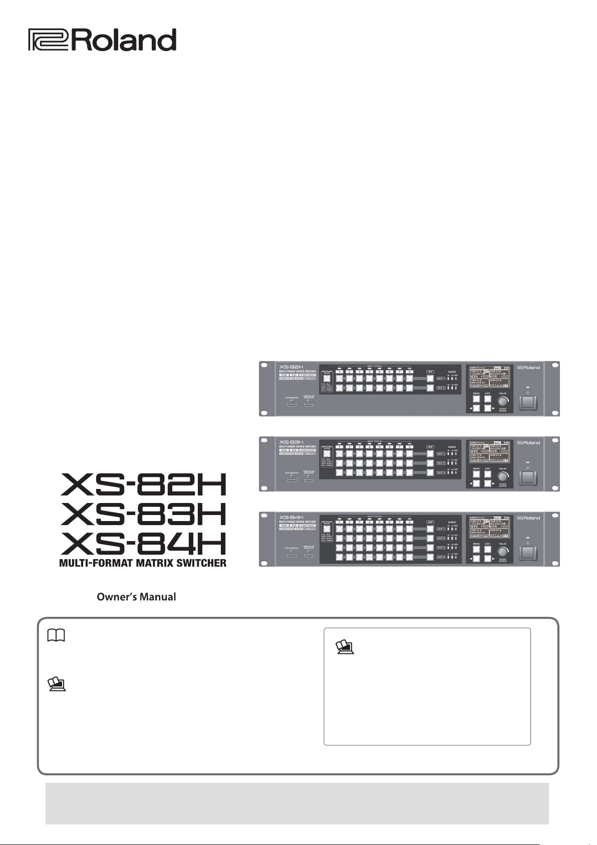
Owner’s Manual (this document)
Read this rst. It explains the basic things you need to know in
order to use the XS-82H/XS-83H/XS-84H.
PDF Manual (download from the Web)
. Reference Manual
This describes all parameters of the XS-82H/XS-83H/XS-84H.
It also describes the settings to make when operating the unit by
remote control.
Copyright © 2014 ROLAND CORPORATION
All rights reserved. No part of this publication may be reproduced in any form without the written permission of ROLAND CORPORATION.
Before using the XS-82H/XS-83H/XS-84H, ensure that its system program is at the most recent version. For information on available upgrades
for the system program, see the Roland website (http://proav.roland.com).
You can check the version of the system program by selecting the [MENU] button
To obtain the PDF manual
1. Enter the following URL in your computer.
http://proav.roland.com
I
2. Go to the XS-82H, XS-83H, or XS-84H
product page and click the “Support” tab.
g “SYSTEM” g “VERSION.”
IMPORTANT SAFETY INSTRUCTIONS
WARNING: To reduce the risk of fire or electric shock, do not expose this apparatus to rain or moisture.
CAUTION
RISK OF ELECTRIC SHOCK
DO NOT OPEN
ATTENTION: RISQUE DE CHOC ELECTRIQUE NE PAS OUVRIR
CAUTION: TO REDUCE THE RISK OF ELECTRIC SHOCK,
DO NOT REMOVE COVER (OR BACK).
NO USER-SERVICEABLE PARTS INSIDE.
REFER SERVICING TO QUALIFIED SERVICE PERSONNEL.
The lightning flash with arrowhead symbol, within an
equilateral triangle, is intended to alert the user to the
presence of uninsulated “dangerous voltage” within the
product’s enclosure that may be of sufficient magnitude to
constitute a risk of electric shock to persons.
The exclamation point within an equilateral triangle is
intended to alert the user to the presence of important
operating and maintenance (servicing) instructions in the
literature accompanying the product.
INSTRUCTIONS PERTAINING TO A RISK OF FIRE, ELECTRIC SHOCK, OR INJURY TO PERSONS.
IMPORTANT SAFETY INSTRUCTIONS
SAVE THESE INSTRUCTIONS
WARNING - When using electric products, basic precautions should always be followed, including the following:
1. Read these instructions.
2. Keep these instructions.
3. Heed all warnings.
4. Follow all instructions.
5. Do not use this apparatus near water.
6. Clean only with a dry cloth.
7. Do not block any of the ventilation openings. Install in
accordance with the manufacturers instructions.
8. Do not install near any heat sources such as radiators,
heat registers, stoves, or other apparatus (including
amplifiers) that produce heat.
9. Do not defeat the safety purpose of the polarized or
grounding-type plug. A polarized plug has two blades with
one wider than the other. A grounding type plug has two
blades and a third grounding prong. The wide blade or the
third prong are provided for your safety. If the provided plug
does not fit into your outlet, consult an electrician for
replacement of the obsolete outlet.
10. Protect the power cord from being walked on or pinched
particularly at plugs, convenience receptacles, and the
point where they exit from the apparatus.
11. Only use attachments/accessories specified
by the manufacturer.
12. Unplug this apparatus during lightning storms or when
unused for long periods of time.
13. Refer all servicing to qualified service personnel. Servicing
is required when the apparatus has been damaged in any
way, such as power-supply cord or plug is damaged, liquid
has been spilled or objects have fallen into the apparatus,
the apparatus has been exposed to rain or moisture, does
not operate normally, or has been dropped.
For the U.K.
WARNING:
IMPORTANT:
As the colours of the wires in the mains lead of this apparatus may not correspond with the coloured markings identifying
the terminals in your plug, proceed as follows:
The wire which is coloured GREEN-AND-YELLOW must be connected to the terminal in the plug which is marked by the
letter E or by the safety earth symbol or coloured GREEN or GREEN-AND-YELLOW.
The wire which is coloured BLUE must be connected to the terminal which is marked with the letter N or coloured BLACK.
The wire which is coloured BROWN must be connected to the terminal which is marked with the letter L or coloured RED.
THIS APPARATUS MUST BE EARTHED
THE WIRES IN THIS MAINS LEAD ARE COLOURED IN ACCORDANCE WITH THE FOLLOWING CODE.
GREEN-AND-YELLOW: EARTH, BLUE: NEUTRAL, BROWN: LIVE
2
AVERTISSEMENT: Pour éviter les risques d’incendie ou de choc électrique, ne pas exposer cet appareil à la pluie ou à l’humidité.
L’éclair éché dans un triangle équilatéral est destiné à
avertir l’utilisateur de la présence, dans l’appareil, d’une
zone non-isolée soumise à une « haute-tension » dont
l’intensité est susante pour constituer un risque
Le point d’exclamation dans un triangle équilatéral est
destiné à attirer l’attention de l’utilisateur sur la
présence d’informations de fonctionnement et
maintenance (entretien) importantes dans la brochure
ATTENTION
RISQUE DE CHOC ÉLECTRIQUE
NE PAS OUVRIR
ATTENTION: RISQUE DE CHOC ÉLECTRIQUE NE PAS OUVRIR
ATTENTION: POUR ÉVITER LES RISQUES DE CHOC ÉLECTRIQUE,
NE PAS OUVRIR LE COUVERCLE (OU L’ARRIÈRE).
AUCUN DES ÉLÉMENTS INTERNES NE DOIT ÊTRE RÉPARÉ PAR L’UTILISATEUR.
NE CONFIER L’ENTRETIEN QU’À UN PERSONNEL QUALIFIÉ.
d’électrocution.
accompagnant l’appareil.
INSTRUCTIONS RELATIVES AUX RISQUES D’INCENDIE, DE CHOC ÉLECTRIQUE OU DE BLESSURES.
INSTRUCTIONS IMPORTANTES DE SÉCURITÉ
CONSERVER CES INSTRUCTIONS
AVERTISSEMENT - Lors de l’utilisation d’appareils électriques, des précautions de base doivent toujours être respectées, y compris ce qui suit :
1. Bien lire ces instructions.
2. Conserver ces instructions.
3. Tenir compte de tous les avertissements.
4. Suivre toutes ces instructions.
5. Ne pas utiliser pas l’appareil près de l’eau.
6. Nettoyer uniquement avec un chion sec.
7. Ne pas obstruer les ouïes de ventilation. Installer
conformément aux instructions du fabricant.
8. Ne pas installer à proximité d’une source de chaleur telle
qu’un radiateur, une bouche de chaleur, un poêle ou
d’autres appareils (dont les amplicateurs) produisant de la
chaleur.
9. Ne pas détériorer la sécurité de la che polarisée ou de la
che de terre. Une che polarisée comporte deux lames
dont l’une est plus large que l’autre. Une che de terre
comporte deux lames et une troisième broche de mise à la
terre. La lame la plus large ou la troisième broche assure la
sécurité de l’utilisateur. Si la che fournie ne s’adapte pas à
la prise électrique, demander à un électricien de remplacer
la prise hors normes.
10. Protéger le cordon d’alimentation an que personne ne
marche dessus et que rien ne le pince, en particulier au
niveau des ches, des prises de courant et du point de
sortie de l’appareil.
11. Utiliser uniquement les pièces / accessoires spéciés par le
fabricant.
12. Débrancher l’appareil pendant les orages ou quand il ne
sera pas utilisé pendant longtemps.
13. Coner toute réparation à du personnel qualié. Des
réparations sont nécessaires si l’appareil est endommagé
d’une façon quelconque, par exemple : cordon ou prise
d’alimentation endommagé, liquide renversé ou objet
tombé à l’intérieur de l’appareil, exposition de l’appareil à la
pluie ou à l’humidité, appareil qui ne marche pas
normalement ou que l’on a fait tomber.
3
Contents
USING THE UNIT SAFELY . . . . . . . . . . . . . . . . . . . . . . . . . . . . . . . . . . . . . . . 5
CONSIGNES DE SÉCURITÉ . . . . . . . . . . . . 7
IMPORTANT NOTES . . . . . . . . . . . . . . . . . . . . . . . . . . . . . . . . . . . . . . . . . . . . 9
Panel Descriptions . . . . . . . . . . . . . . . . . . . . . . . . . . . . . . . . . . . . . . . . . . . . 10
Front Panel/Top Panel/Side Panel . . . . . . . . . . . . . . . . . . . . . . . . . . . . . . 10
Rear Panel . . . . . . . . . . . . . . . . . . . . . . . . . . . . . . . . . . . . . . . . . . . . . . . . . . 12
Placement and Setup . . . . . . . . . . . . . . . . . . . . . . . . . . . . . . . . . . . . . . . . . 13
Important Notes on Rack Mounting . . . . . . . . . . . . . . . . . . . . . . . . . . . . 13
Attaching the Rubber Feet . . . . . . . . . . . . . . . . . . . . . . . . . . . . . . . . . . . . 13
Connecting Cables to the Euroblock Plugs . . . . . . . . . . . . . . . . . . . . . . 13
Connecting External Equipment . . . . . . . . . . . . . . . . . . . . . . . . . . . . . . 14
Connecting Video Source/Output Equipment . . . . . . . . . . . . . . . . . . . 14
Connecting Audio Source/Output Equipment . . . . . . . . . . . . . . . . . . .15
Using Phantom Power . . . . . . . . . . . . . . . . . . . . . . . . . . . . . . . . 15
Connecting the Power Cord . . . . . . . . . . . . . . . . . . . . . . . . . . . . . . . . . . . 16
Basic Operation . . . . . . . . . . . . . . . . . . . . . . . . . . . . . . . . . . . . . . . . . . . . . . . 17
Turning the Power On and O . . . . . . . . . . . . . . . . . . . . . . . . . . . . . . . . . 17
Using the Menus. . . . . . . . . . . . . . . . . . . . . . . . . . . . . . . . . . . . . . . . . . . . . 17
Changing the View on the Display . . . . . . . . . . . . . . . . . . . . . . . . . . . . . 18
Changing Audio Fader Assignments . . . . . . . . . . . . . . . . . . . . 18
Video Operations . . . . . . . . . . . . . . . . . . . . . . . . . . . . . . . . . . . . . . . . . . . . . 19
Setting the Video Signal for Each Video Input Channel . . . . . . . . . . . . 19
Sharing a Video Source (SHARE) . . . . . . . . . . . . . . . . . . . . . . . . 19
Changing Cross Points . . . . . . . . . . . . . . . . . . . . . . . . . . . . . . . . . . . . . . . .19
Inputting/Outputting Copyright-protected (HDCP) Video . . . . . . . . . 20
Switching Between HDMI Output and HDBaseT Output . . . . . . . . . .21
Outputting an Imported Still Image . . . . . . . . . . . . . . . . . . . . . . . . . . . . 21
Switching the Video Output Mode . . . . . . . . . . . . . . . . . . . . . . . . . . . . . 22
Applying a Fade to Output Video . . . . . . . . . . . . . . . . . . . . . . . . . . . . . . 24
Audio Operations . . . . . . . . . . . . . . . . . . . . . . . . . . . . . . . . . . . . . . . . . . . . . 25
Adjusting Microphone Gain . . . . . . . . . . . . . . . . . . . . . . . . . . . . . . . . . . . 25
Adjusting the Volume Balance of Input Audio . . . . . . . . . . . . . . . . . . . 25
Adjusting the Volume Level of Output Audio . . . . . . . . . . . . . . . . . . . . 26
Other Features . . . . . . . . . . . . . . . . . . . . . . . . . . . . . . . . . . . . . . . . . . . . . . . .27
Saving/Recalling Settings (Presets) . . . . . . . . . . . . . . . . . . . . . . . . . . . . . 27
Saving Settings on a USB Flash Drive . . . . . . . . . . . . . . . . . . . 27
Formatting USB Flash Drives . . . . . . . . . . . . . . . . . . . . . . . . . . . . . . . . . . 28
Returning Settings to the Factory-default State (Factory Reset) . . . . 28
Remote Control from an External Device . . . . . . . . . . . . . . . . . . . . . . . . 28
Appendices . . . . . . . . . . . . . . . . . . . . . . . . . . . . . . . . . . . . . . . . . . . . . . . . . . . 29
Troubleshooting . . . . . . . . . . . . . . . . . . . . . . . . . . . . . . . . . . . . . . . . . . . . . 29
Block Diagram . . . . . . . . . . . . . . . . . . . . . . . . . . . . . . . . . . . . . . . . . . . . . . . 31
Connector Specications . . . . . . . . . . . . . . . . . . . . . . . . . . . . . . . . . . . . .32
Analog video INPUT connectors . . . . . . . . . . . . . . . . . . . . . . . 32
RS-232C connector . . . . . . . . . . . . . . . . . . . . . . . . . . . . . . . . . . . 32
AUDIO INPUT/OUTPUT connectors . . . . . . . . . . . . . . . . . . . . . 33
Main Specications . . . . . . . . . . . . . . . . . . . . . . . . . . . . . . . . . . . . . . . . . .34
Dimensions . . . . . . . . . . . . . . . . . . . . . . . . . . . . . . . . . . . . . . . . . . . . . . . . . 36
* Before using this unit, carefully read the sections entitled
“IMPORTANT SAFETY INSTRUCTIONS” (p. 2), “USING THE UNIT
SAFELY” (p. 5), and “IMPORTANT NOTES” (p. 9). These sections
provide important information concerning the proper operation
of the unit. Additionally, in order to feel assured that you have
gained a good grasp of every feature of your new unit, read
Owner’s Manual in its entirety. This manual should be saved and
kept on hand as a convenient reference.
* The explanations of operation procedures in this document use
illustrations of the XS-84H.
Unless explicitly indicated to be for a specic model (such as “XS-84H
only”), the explanations also cover the XS-82H and XS-83H as well.
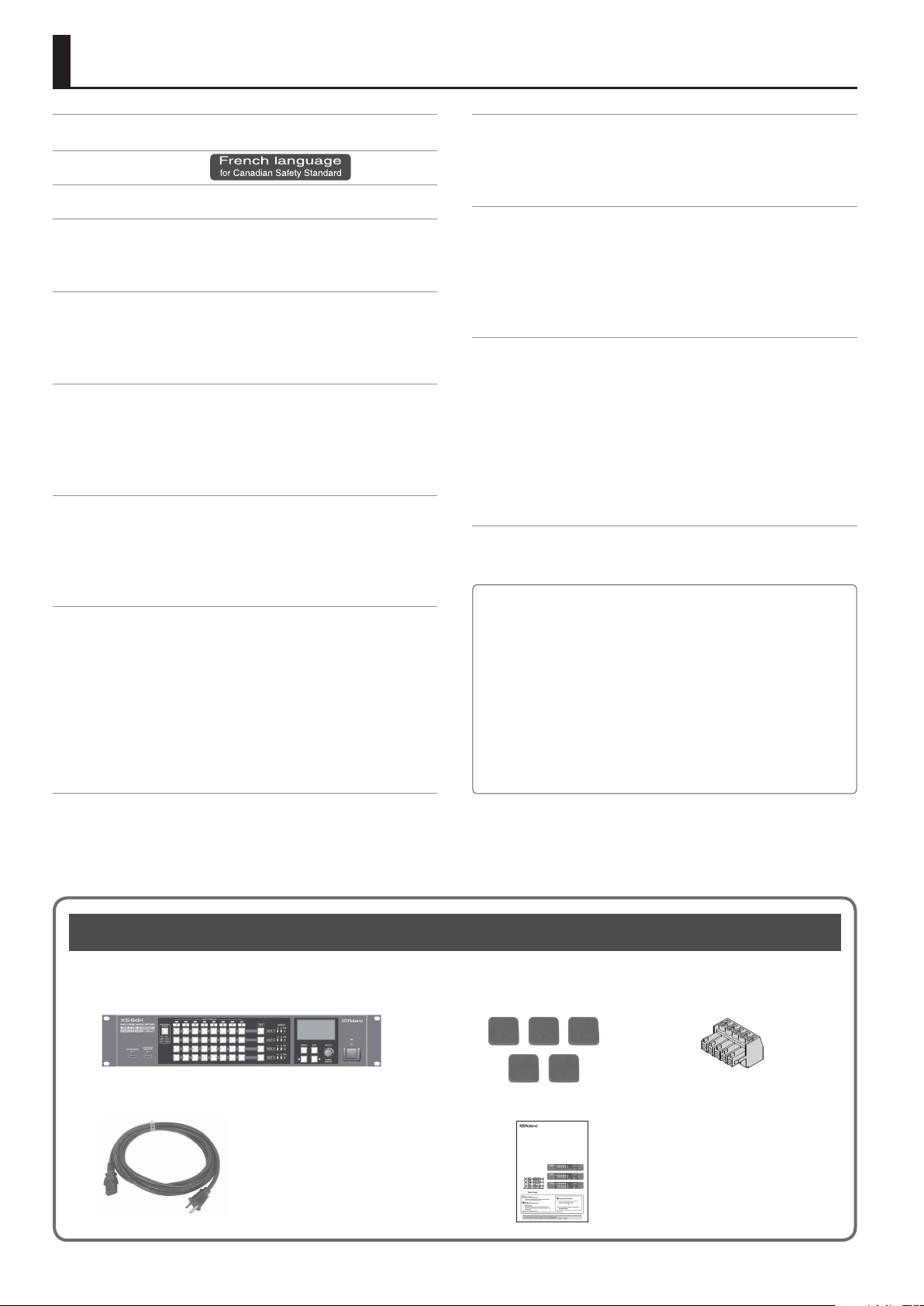
Checking the Included Items
The following items are included with this unit. Check to make sure that all items are present. If anything is missing, contact your dealer.
The unit Rubber foot (5) Euroblock plug (12)
* The appearance of each model diers.
Power cord Owner’s Manual
* The shape of the power cord’s plug
varies depending on the country.
4
USING THE UNIT SAFELY
About WARNING and CAUTION Notices
Used for instructions intended to alert the
user to the risk of death or severe injury
should the unit be used improperly.
Used for instructions intended to alert the
user to the risk of injury or material
damage should the unit be used
improperly.
* Material damage refers to damage or
other adverse effects caused with
respect to the home and all its
furnishings, as well to domestic animals
or pets.
ALWAYS OBSERVE THE FOLLOWING
001-50
Make sure that the power cord is grounded
Connect mains plug of this model to a
mains socket outlet with a protective
earthing connection.
001-60
To completely turn o power to the unit, pull out
the plug from the outlet
Even with the power switch turned o, this
unit is not completely separated from its
main source of power. When the power
needs to be completely turned o, turn o
the power switch on the unit, then pull out the plug
from the outlet. For this reason, the outlet into which
you choose to connect the power cord’s plug should
be one that is within easy reach and readily accessible.
001-75
Secure a sucient amount of space at the setup
location
Since this unit normally emits a slight
amount of heat, make sure to secure
sucient space around it, as shown below.
30 cm (12 in.)
or greater
20 cm (8 in.)
or greater
002a
Do not disassemble or modify by yourself
Do not carry out anything unless you are
instructed to do so in the owner’s manual.
Otherwise, you risk causing malfunction.
003
Do not repair or replace parts by yourself
Refer all servicing to your retailer, the
nearest Roland Service Center, or an
authorized Roland distributor, as listed on
the “Information.”
WARNING
Front Side
5 cm (2 in.)
or greater
20 cm (8 in.)
or greater
15 cm (6 in.)
or greater
About the Symbols
The symbol alerts the user to important instructions or
warnings.The specific meaning of the symbol is
determined by the design contained within the triangle. In
the case of the symbol at left, it is used for general
cautions, warnings, or alerts to danger.
The symbol alerts the user to items that must never be
carried out (are forbidden). The specific thing that must
not be done is indicated by the design contained within
the circle. In the case of the symbol at left, it means that
the unit must never be disassembled.
The symbol alerts the user to things that must be
carried out. The specific thing that must be done is
indicated by the design contained within the circle. In the
case of the symbol at left, it means that the power-cord
plug must be unplugged from the outlet.
004
Do not use or store in the following types of
locations
• Subject to temperature extremes (e.g.,
direct sunlight in an enclosed vehicle,
near a heating duct, on top of heatgenerating equipment); or are
• Damp (e.g., baths, washrooms, on wet
oors); or are
• Exposed to steam or smoke; or are
• Subject to salt exposure; or are
• Exposed to rain; or are
• Dusty or sandy; or are
• Subject to high levels of vibration and shakiness.
007
Do not place in an unstable location
Otherwise, you risk injury as the result of
the unit toppling over or dropping down.
008e
Use only the supplied power cord
Use only the attached power cord. Also,
the supplied power cord must not be used
with any other device.
008f
Connect the power cord to an outlet of the correct
voltage
The unit should be connected to a power
supply only of the type described in the
operating instructions, or as marked on the
rear side of unit.
009
Do not bend the power cord or place heavy objects
on it
Otherwise, re or electric shock may result.
010
Avoid extended use at high volume
Use of the unit at high volume for
extended periods of time may cause
hearing loss. If you ever experience any
hearing loss or ringing in the ears, you
should immediately stop using the unit
and consult a specialized physician.
WARNING
011
Do not allow foreign objects or liquids to enter
WARNING
unit; never place containers with liquid on unit
Do not place containers containing liquid
(e.g., ower vases) on this product. Never
allow foreign objects (e.g., ammable
objects, coins, wires) or liquids (e.g., water
or juice) to enter this product. Doing so
may cause short circuits, faulty operation,
or other malfunctions.
012a
Turn o the unit if an abnormality or malfunction
occurs
Immediately turn the unit o, remove the
power cord from the outlet, and request
servicing by your retailer, the nearest
Roland Service Center, or an authorized
Roland distributor, as listed on the “Information” when:
• The power cord has been damaged; or
• If smoke or unusual odor occurs; or
• Objects have fallen into, or liquid has been spilled
onto the unit; or
• The unit has been exposed to rain (or otherwise has
become wet); or
• The unit does not appear to operate normally or
exhibits a marked change in performance.
014
Do not drop or subject to strong impact
Otherwise, you risk causing damage or
malfunction.
015
Do not share an outlet with an unreasonable
number of other devices
Otherwise, you risk overheating or re.
016
Do not use overseas
Before using the unit in overseas, consult
with your retailer, the nearest Roland
Service Center, or an authorized Roland
distributor, as listed on the “Information.”
5
USING THE UNIT SAFELY
101a
Place in a well ventilated location
The unit should be located so that its
location or position does not interfere with
its proper ventilation.
102b
When disconnecting the power cord, grasp it by the
CAUTION
plug
To prevent conductor damage, always
grasp the power cord by its plug when
disconnecting it from this unit or from a
power outlet.
103a
Periodically clean the power plug
An accumulation of dust or foreign objects
between the power plug and the power
outlet can lead to re or electric shock.
At regular intervals, be sure to pull out the
power plug, and using a dry cloth, wipe away any dust
or foreign objects that may have accumulated.
103c
Disconnect the power plug whenever the unit will
not be used for an extended period of time
Fire may result in the unlikely event that a
breakdown occurs.
104
Route all power cords and cables in such a way as
to prevent them from getting entangled
Injury could result if someone were to
trip on a cable and cause the unit to fall
or topple.
106
Avoid climbing on top of the unit, or placing heavy
objects on it
Otherwise, you risk injury as the result of
the unit toppling over or dropping down.
107a
Never connect/disconnect a power plug if your
hands are wet
Otherwise, you could receive an electric
shock.
108a
Disconnect all cords/cables before moving the unit
Before moving the unit, disconnect the
power plug from the outlet, and pull out all
cords from external devices.
109a
Before cleaning the unit, disconnect the power
plug from the outlet
If the power plug is not removed from the
outlet, you risk receiving an electric shock.
110a
Whenever there is a threat of lightning, disconnect
the power plug from the outlet
If the power plug is not removed from the
outlet, you risk receiving an electric shock.
120
Precautions concerning use of phantom power
supply
Always turn the phantom power o
when connecting any device other than
condenser microphones that require
phantom power. You risk causing damage
if you mistakenly supply phantom power to dynamic
microphones, audio playback devices, or other devices
that don’t require such power. Be sure to check the
specications of any microphone you intend to use by
referring to the manual that came with it.
(This instrument’s phantom power: 48 V DC, 14 mA
Max)
6
CONSIGNES DE SÉCURITÉ
PROCÉDEZ TOUJOURS COMME SUIT
INSTRUCTIONS POUR LA PRÉVENTION DES INCENDIES, CHOCS ÉLECTRIQUES OU BLESSURES
À propos des mentions AVERTISSEMENT
et ATTENTION
AVERTISSEMENT
ATTENTION
Utilisé pour avertir l’utilisateur d’un
risque de décès ou de blessure grave en
cas de mauvaise utilisation de l’appareil.
Utilisé pour avertir l’utilisateur d’un
risque de blessure ou de dommage
matériel en cas de mauvaise utilisation
de l’appareil.
* Par dommage matériel, il est entendu
les dommages ou tout autre eet
indésirable sur la maison et tous ses
meubles ainsi que les animaux
domestiques ou familiers.
À propos des symboles
TLe symbole alerte l’utilisateur d’instructions importantes
ou de mise en garde. La signication du symbole est
déterminée par ce que contient le triangle. Dans le cas du
symbole de gauche, il sert pour des précautions générales,
des mises en garde ou alertes vis-à-vis d’un danger.
Le symbole prévient l’utilisateur des choses à ne pas faire
(des interdits). Ce qui ne doit spéciquement pas être fait est
indiqué dans le cercle. Dans le cas du symbole de gauche, cela
signie que l’appareil ne doit jamais être démonté.
Le symbole alerte l’utilisateur des choses à faire. Ce qui
doit être fait est indiqué par l’icône contenue dans le cercle.
Dans le cas du symbole de gauche, cela signie que le cordon
d’alimentation doit être débranché de la prise murale.
001-50
S’assurer que le cordon d’alimentation est bien mis
AVERTISSEMENT
à la terre
Connectez la che secteur de ce modèle
à une prise de courant dotée d’une
protection par mise à la terre.
001-60
Pour éteindre complètement l’alimentation de
l’appareil, retirer la che de la prise
Même avec son interrupteur
d’alimentation hors tension, l’appareil
n’est pas complètement isolé de sa
source principale d’alimentation. Lorsque
l’alimentation doit être complètement coupée,
éteignez l’interrupteur d’alimentation de l’appareil
puis retirez la che de la prise. Pour cette raison, la
prise dans laquelle vous choisissez de brancher la
che du cordon d’alimentation doit être proche et
facilement accessible.
001-75
Ménager un espace susant à l’emplacement
d’installation
Comme l’appareil émet normalement une
faible quantité de chaleur, assurez-vous de
ménager susamment d’espace autour de
lui, comme indiqué ci-dessous.
Avant Côté
30 cm (12 in.)
ou plus
20 cm (8 in.)
ou plus
002a
Ne jamais démonter ou modier vous-même
Ne jamais eectuer une quelconque
opération, sauf si vous êtes invité à le
faire dans le manuel du propriétaire.
Sinon, vous risquez de provoquer des
dysfonctionnements.
003
Ne pas réparer ou remplacer de pièces par
5 cm (2 in.)
ou plus
20 cm (8 in.)
ou plus
15 cm (6 in.)
ou plus
vous-même
Conez toute réparation à votre revendeur,
le centre Roland le plus proche ou un
distributeur Roland agréé, comme indiqué
dans les « Informations ».
004
Ne jamais ranger ou utiliser dans des endroits:
• Soumis à des températures
extrêmes (ex : en plein soleil dans
un véhicule fermé, à proximité d’une
conduite de chauage, au-dessus de
matériel générateur de chaleur),
• humides (ex : salles de bain, toilettes, sur
des sols mouillés), ou
• exposés à de la vapeur ou de la fumée,
ou
• exposés au sel, ou
• exposés aux précipitations, ou
• poussiéreux ou sableux, ou
• soumis à de fortes vibrations et secousses.
007
Ne pas placer à un endroit instable
Sinon, vous risquez des blessures si
l’appareil se renverse ou tombe.
008e
Utilisez uniquement le cordon d’alimentation
AVERTISSEMENT
fourni
Utilisez exclusivement le cordon
d’alimentation inclus. De plus, le cordon
d’alimentation fourni ne doit pas être
utilisé avec un autre appareil.
008f
Brancher le cordon d’alimentation à une prise
d’une tension correcte
L’appareil doit être connecté à une source
d’alimentation du type décrit dans les
instructions d’utilisation, ou comme
indiqué sur la face arrière de l’appareil.
009
Ne pas plier le cordon d’alimentation ou déposer
d’objets lourds sur celui-ci
Sinon, cela risque de provoquer un
incendie ou un choc électrique.
010
Éviter l’utilisation prolongée à un volume élevé
L’utilisation de l’appareil à un volume élevé
pendant des périodes prolongées peut
entraîner une perte auditive. Si jamais
vous ressentez une perte auditive ou des
bourdonnements dans les oreilles, veuillez
immédiatement cesser d’utiliser l’appareil et consultez
un médecin spécialisé.
011
Ne jamais laisser de corps étrangers ou de liquides
AVERTISSEMENT
pénétrer dans l’appareil et ne jamais placer de
récipients contenant un liquide sur l’appareil
Ne jamais placer de récipients contenant
du liquide (ex : vases de eurs) sur ce
produit. Ne jamais laisser des corps
étrangers (ex : objets inammables, pièces,
ls) ou des liquides (ex : eau, jus de fruit)
pénétrer à l’intérieur du produit. Vous
risqueriez de provoquer des courts-circuits,
pannes ou autres dysfonctionnements.
012a
Eteindre l’appareil en cas d’anomalie ou de
dysfonctionnement
Mettez immédiatement l’appareil
hors tension, débranchez le cordon
d’alimentation de la prise et contactez
votre revendeur, le centre Roland le plus
proche ou un distributeur Roland agréé, comme
indiqué dans les « Informations » lorsque:
• Le cordon d’alimentation a été endommagé, ou
• en présence de fumée ou odeur inhabituelle, ou
• des objets sont tombés dans ou du liquide a été
renversé dans l’appareil, ou
• l’appareil a été exposé à la pluie (ou a été mouillé),
ou
• l’appareil ne semble pas fonctionner normalement
ou présente un changement notable de ses
performances.
014
Ne pas faire tomber ou soumettre à des chocs
violents
Sinon, vous risquez de provoquer des
dommages ou des dysfonctionnements.
015
Ne pas partager une prise murale avec un nombre
excessif d’autres appareils
Sinon, vous risquez une surchaue ou un
incendie.
016
Ne pas utiliser à l’étranger
Avant d’utiliser l’appareil à l’étranger,
consultez votre revendeur, un centre
Roland ou un distributeur Roland agréé,
comme indiqué dans les « informations ».
7
USING THE UNIT SAFELY
101a
Placer dans un endroit bien ventilé
L’appareil doit être placé en veillant à ce
que son emplacement ou sa position ne
gêne pas sa propre ventilation.
102b
Lorsque vous débranchez le cordon d’alimentation,
ATTENTION
saisissez-le par la che
Pour éviter d’endommager le conducteur,
toujours saisir le cordon d’alimentation
par sa che lorsque vous le débranchez de
l’appareil ou d’une prise de courant.
103a
Nettoyer régulièrement le cordon d’alimentation
Une accumulation de poussière ou
de corps étrangers entre la che
d’alimentation et la prise de courant
peut provoquer un incendie ou un choc
électrique.
A intervalles réguliers, assurez-vous de débrancher
la prise d’alimentation, et à l’aide d’un chion sec,
essuyez la poussière ou les corps étrangers qui ont pu
s’y accumuler.
103c
Débrancher le cordon d’alimentation lorsque
l’appareil n’est pas utilisé pendant une longue
période
Un incendie peut se produire dans le cas
fortuit où une panne survient.
104
Acheminer tous les cordons d’alimentation et
câbles de façon à ce qu’ils ne puissent pas
s’emmêler
Des blessures peuvent survenir si
quelqu’un vient à trébucher sur un câble
et provoque la chute ou le basculement
de l’appareil
106
Ne pas grimper sur l’appareil ou y poser des objets
lourds
Sinon, vous risquez des blessures suite à la
chute ou au basculement de l’appareil.
120
Précautions concernant l’utilisation de
ATTENTION
l’alimentation fantôme
Toujours éteindre l’alimentation fantôme
avant de brancher tout autre appareil
qu’un microphone à condensateur
nécessitant une alimentation fantôme.
Vous risquez de provoquer des dommages si vous
fournissez à tort une alimentation fantôme à des
micros dynamiques, des appareils de lecture audio
ou d’autres appareils qui ne nécessitent pas une telle
alimentation. Assurez-vous de vérier les spécications
de tout microphone que vous souhaitez utiliser en
vous référant au manuel qui l’accompagne.
(Alimentation fantôme de cet instrument: 48 V DC,
14 mA Max)
107a
Ne jamais brancher / débrancher un cordon
d’alimentation lorsque vous avez les mains
mouillées
Sinon, vous pourriez subir un choc
électrique.
108a
Débrancher tous les cordons / câbles avant de
déplacer l’appareil
Avant de déplacer l’appareil, débrancher le
cordon d’alimentation de la prise et retirer
tous les cordons des appareils externes.
109a
Avant de nettoyer l’appareil, débrancher le cordon
d’alimentation de la prise
Si la che d’alimentation n’est pas
débranchée de la prise, vous risquez de
subir un choc électrique.
110a
Chaque fois qu’il y a un risque de foudre,
débrancher le cordon d’alimentation de la prise
Si la che d’alimentation n’est pas
débranchée de la prise, vous risquez de
subir un choc électrique.
8

IMPORTANT NOTES
Power Supply
• Do not connect this unit to same electrical outlet
that is being used by an electrical appliance that
is controlled by an inverter or a motor (such as a
refrigerator, washing machine, microwave oven, or
air conditioner). Depending on the way in which
the electrical appliance is used, power supply noise
may cause this unit to malfunction or may produce
audible noise. If it is not practical to use a separate
electrical outlet, connect a power supply noise lter
between this unit and the electrical outlet.
Placement
• Using the unit near power ampliers (or other
equipment containing large power transformers)
may induce hum. To alleviate the problem, change
the orientation of this unit; or move it farther away
from the source of interference.
352a
• This unit may interfere with radio and television
reception. Do not use this unit in the vicinity of such
receivers.
• Noise may be produced if wireless communications
devices, such as cell phones, are operated in the
vicinity of this unit. Such noise could occur when
receiving or initiating a call, or while conversing.
Should you experience such problems, you should
relocate such wireless devices so they are at a
greater distance from this unit, or switch them o.
354a
• Do not expose the unit to direct sunlight, place
it near devices that radiate heat, leave it inside
an enclosed vehicle, or otherwise subject it to
temperature extremes. Excessive heat can deform
or discolor the unit.
355b
• When moved from one location to another where
the temperature and/or humidity is very dierent,
water droplets (condensation) may form inside
the unit. Damage or malfunction may result if you
attempt to use the unit in this condition. Therefore,
before using the unit, you must allow it to stand
for several hours, until the condensation has
completely evaporated.
360
• Depending on the material and temperature of the
surface on which you place the unit, its rubber feet
may discolor or mar the surface.
You can place a piece of felt or cloth under the
rubber feet to prevent this from happening. If you
do so, please make sure that the unit will not slip or
move accidentally.
361
• Do not place containers or anything else containing
liquid on top of this unit. Also, whenever any liquid
has been spilled on the surface of this unit, be sure
to promptly wipe it away using a soft, dry cloth.
Maintenance
401a
• For everyday cleaning wipe the unit with a soft,
dry cloth or one that has been slightly dampened
with water. To remove stubborn dirt, use a cloth
impregnated with a mild, non-abrasive detergent.
Afterwards, be sure to wipe the unit thoroughly
with a soft, dry cloth.
402
• Never use benzine, thinners, alcohol or solvents of
any kind, to avoid the possibility of discoloration
and/or deformation.
Repairs and Data
452
• Before sending the unit away for repairs, be sure to
make a backup of the data stored within it; or you
may prefer to write down the needed information.
Although we will do our utmost to preserve the
data stored in your unit when we carry out repairs,
in some cases, such as when the memory section
is physically damaged, restoration of the stored
content may be impossible. Roland assumes no
liability concerning the restoration of any stored
content that has been lost.
Additional Precautions
551
• Any data stored within the unit can be lost as the
result of equipment failure, incorrect operation,
etc. To protect yourself against the irretrievable
loss of data, try to make a habit of creating regular
backups of the data you’ve stored in the unit.
552
• Roland assumes no liability concerning the
restoration of any stored content that has been lost.
553
• Use a reasonable amount of care when using the
unit’s buttons, sliders, or other controls; and when
using its jacks and connectors. Rough handling can
lead to malfunctions.
556
• When disconnecting all cables, grasp the connector
itself—never pull on the cable. This way you will
avoid causing shorts, or damage to the cable’s
internal elements.
557
• A small amount of heat will radiate from the unit
during normal operation.
558
• To avoid disturbing others nearby, try to keep the
unit’s volume at reasonable levels.
559b
• When you need to transport the unit, pack it in
shock-absorbent material. Transporting the unit
without doing so can cause it to become scratched
or damaged, and could lead to malfunction.
568
• This unit allows you to switch images at high speed.
For some people, viewing such images can cause
headache, nausea, or other discomfort. Do not use
this unit to create video that might cause these
types of health problems. Roland Corporation
will accept no responsibility for any such health
problems that may occur in yourself or in viewers.
Using External Memories
709
• Please observe the following precautions when
handling external memory devices. Also, make sure
to carefully observe all the precautions that were
supplied with the external memory device.
• Do not remove the device while reading/writing
is in progress.
• To prevent damage from static electricity,
discharge all static electricity from your person
before handling the device.
Intellectual Property Right
C-02
• This product can be used to record or duplicate
audio or visual material without being limited by
certain technological copy-protection measures.
This is due to the fact that this product is intended
to be used for the purpose of producing original
music or video material, and is therefore designed
so that material that does not infringe copyrights
belonging to others (for example, your own original
works) can be recorded or duplicated freely.
• MMP (Moore Microprocessor Portfolio) refers to a
patent portfolio concerned with microprocessor
architecture, which was developed by Technology
Properties Limited (TPL). Roland has licensed this
technology from the TPL Group.
R-01
• Roland is an either registered trademark or
trademark of Roland Corporation in the United
States and/or other countries.
T-01
• Company names and product names appearing
in this document are registered trademarks or
trademarks of their respective owners.
9
Panel Descriptions
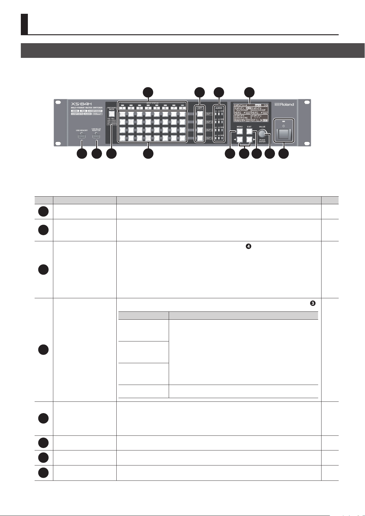
Front Panel/Top Panel/Side Panel
5 6 7 8
XS-84H
No. Name Explanation Page
USB MEMORY connector
1
USB WLAN ADAPTOR connector
2
[SWITCHING MODE] button
3
Cross-point selection buttons
4
1 2
3 4
This is for connecting a USB ash drive. You use this when saving or loading settings, or when importing still
images.
Here you connect a wireless USB adapter (sold separately) for making a Wi-Fi connection to an iPad.
You use this when operating the unit remotely using the XS-80H Remote iPad application.
* For the wireless USB adaptor, use the ONKYO UWF-1 or Roland WNA1100-RL.
This switches the operation mode of the cross-point selection buttons (
cycle through the modes in this sequence: video and audio interlink mode g video independent mode g audio
independent mode g preset mode.
The color of the lighted button indicates the operation mode.
5 Lighted in yellow: Video and audio interlink mode
5 Lighted in green: Video independent mode
5 Lighted in red: Audio independent mode
5 Lighted in blue: Preset mode
These function as follows, according to the operation mode selected using the [SWITCHING MODE] button (
Operation mode Functioning of the cross-point selection buttons
Video and audio interlink
mode
Video independent mode
Audio independent mode
Preset mode
These switch the cross points for the video or audio channels. According
to the operation mode, they can switch the video and audio in tandem, or
independently switch only the video or only the audio.
Each button’s horizontal direction is the input channel and vertical direction is
the output channel.
The current selection of audio or video channel is indicated by the color of the
lighted button.
5 Lighted in yellow: Video channel and audio channel
5 Lighted in green: Video channel only
5 Lighted in red: Audio channel only
These function as memory-number selection buttons. These buttons access
preset settings that have been saved.
9 10 11 12 13
). Successive presses of the button
p. 21
p. 27
p. 28
p. 19
p. 27
).
p. 19
p. 27
10
These indicate the type of video signal being input.
INPUT STATUS indicators
5
[OFF] buttons
6
AUDIO level meters These indicate the volume levels on the output channels. p. 26
7
Display These display information about input and output video, menu items, and the like. p. 18
8
5 Lighted in blue: HDMI signal
5 Lighted in red: Analog video signal (RGB/component, composite, Y/C)
5 Lighted up in white: Still picture
5 Dark: No input signal
These apply fade to the output video and output a picture of a single color (speciable). The corresponding [OFF]
button lights up when the video fade-out is complete.
p. 19
p. 24
Panel Descriptions
14
1414
No. Name Explanation Page
[MENU] button This displays the menu. p. 17
9
5 During menu display, these move the cursor. Also, depending on the menu item, they move to the setting
10
[ ][ ] (cursor) buttons
[EXIT] button This exits the menus. When the system is at a lower-level menu, these return operation to the upper menu. p. 17
11
[VALUE] knob
12
Power indicator
13
Power button
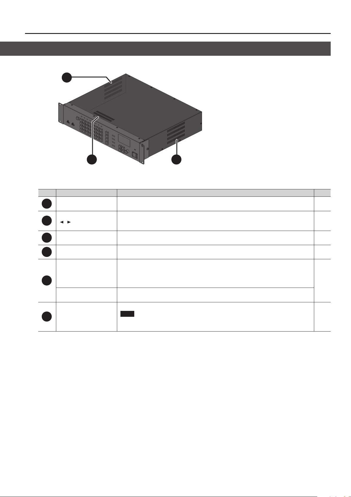
Cooling-fan exhaust port
14
screen for a dierent channel or the like.
5 These change the view mode for the top screen of the display.
This selects menu items and changes setting values. Pressing the [VALUE] dial applies a selected menu item or
changes made to a setting value.
This indicates the power state.
5 Lighted in red: Standby
5 Lighted in green: Powered
5 Dark: Main power o
This switches the power between on and standby.
* This is enabled only when the [POWER] (main power) switch is set to “ON.”
This expels internal heat to keep temperatures inside the unit from rising excessively.
NOTE
Never block the cooling-fan exhaust port. Blocking the exhaust port might result in a rise in temperature
inside the unit, resulting in malfunction due to heat.
p. 17
p. 18
p. 17
p. 17
-
11
Panel Descriptions
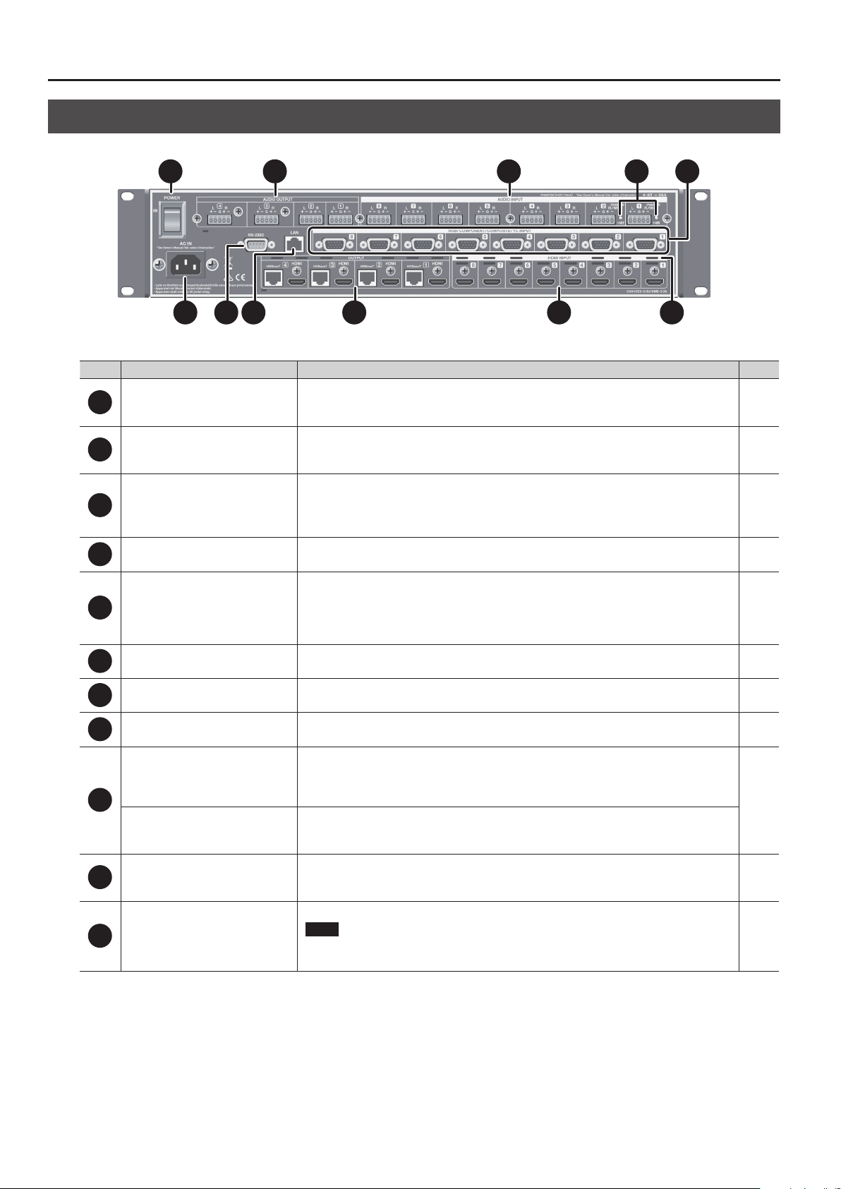
Rear Panel
1 2 3 4 5
XS-84H
No. Name Explanation Page
[POWER] (main power) switch
1
AUDIO OUTPUT connectors
2
AUDIO INPUT connectors
3
Phantom power indicator This indicator lights up when phantom power (+48 V) is turned on. p. 14
4
Analog video INPUT connectors
(RGB/COMPONENT/COMPOSITE/YC
5
INPUT connectors)
AC IN connector This is for connecting the included power cord. p. 16
6
RS-232C connector
7
6 7 8
9 10 11
This turns the main power on and o.
When the main power has been turned on, the power button on the front panel can be used to switch
the power to on or standby.
These are 5p Euroblock connectors for output of analog audio signals. Recording units, power amps,
speakers, and other devices are connected to these.
* To make connections, use the included Euroblock plugs (p. 13).
These are 5p Euroblock connectors for input of analog audio signals. You connect audio decks,
microphones, and other such devices to these.
* To make connections, use the included Euroblock plugs (p. 13).
* AUDIO INPUT connectors 1 and 2 can supply phantom power (+48 V).
These are D-Sub 15-pin connectors for input of analog video signals. In addition to RGB signals, using
conversion cables lets you input component, composite, and Y/C (S-Video) signals. You connect video
decks, computers, and other such devices to these.
* Inputting video requires setting the type of video signal (RGB/component, composite, or Y/C) for each
input video channel.
This is for connecting a remote-control device (such as an RS-232C-compatible computer) for operating
the unit remotely.
p. 17
p. 14
p. 14
p. 14
p. 28
LAN port This is for connecting a computer or other network-capable equipment for operating the unit remotely. p. 28
8
These output HDMI signals. External displays or other devices equipped with HDMI input connectors are
HDMI OUTPUT connectors
9
HDBaseT OUTPUT connectors
HDMI INPUT connectors
10
Cooling-fan exhaust port
11
connected to these.
* Simultaneously outputting video from both the HDMI output connector and the HDBaseT output
connector on the same channel is not possible.
These output HDBaseT signals. Projectors or other devices equipped with HDBaseT input connectors are
connected to these.
* To make connections, use a Cat 5e (Category 5e) or later shielded LAN cable.
These are for inputting HDMI signals. Video devices equipped with HDMI output connectors are
connected to these.
* Inputting video requires setting the type of video signal (HDMI) for each input video channel.
This expels internal heat to keep temperatures inside the unit from rising excessively.
NOTE
Never block the cooling-fan exhaust port. Blocking the exhaust port might result in a rise in
temperature inside the unit, resulting in malfunction due to heat.
p. 14
p. 21
p. 15
-
12

Placement and Setup
Important Notes on Rack Mounting
* When mounting the unit in a rack, to ensure ecient cooling, give
attention to the following points.
5 Install in a well-ventilated location.
5 Never obstruct the exhaust ports on the unit’s top, rear, and side
panels.
5 Avoid mounting the unit in a sealed-type rack. Warm air within
the rack cannot escape and is sucked into the unit, making
ecient cooling impossible.
5 If the back of the rack cannot be opened, install an exhaust port
or ventilation fan at the top back surface of the rack, where
warm air collects.
5 When using the unit while mounted in a movable case (portable
rack), remove the front and rear rack covers so that the front and
back of the unit are not obstructed.
* When installing the unit in a rack or the like, use the mounting
screws occupying the screw holes in the rack-mount brackets
(included with the unit). Also, use due caution to ensure that your
ngers don’t get pinched.
* Also read the “Placement” section (p. 9) under “IMPORTANT NOTES.”
Attaching the Rubber Feet
Connecting Cables to the Euroblock Plugs
Attach cables to the included Euroblock plug and connect them to the
AUDIO INPUT and OUTPUT connectors.
1. Prepare the cables.
Strip o about 5 mm of insulation from the tip of each cable and
tightly twist the core wires.
* To avoid electromagnetic noise and other such trouble, we
recommend using shielded cables.
5mm
NOTE
Never apply solder to the insulation-stripped section of the cable.
2. Attach the cable to the Euroblock plug.
Use a commercially available athead screwdriver to loosen the
connector screw.
Insert the cable prepared in step 1, then secure it in place by
tightening the connector screw using the athead screwdriver.
Tighten
Loosen
When using the unit with it unmounted in a rack, attach the
included rubber feet (5) if necessary.
1. Peel o the double-sided tape from the rubber feet and
ax the rubber feet at the locations shown in the gure.
Connector screw
Important Notes When Wiring
The AUDIO INPUT and OUTPUT connectors are wired as
shown in the gure below.
L R
COLD HOT
HOT COLD
GND
Wire the cables correctly, according to whether you’re
using balanced or unbalanced connections.
* For information on how to carry out wiring, refer to
“AUDIO INPUT/OUTPUT connectors” (p. 33).
3. Insert the Euroblock plug into the AUDIO INPUT or
OUTPUT connector on the unit.
13

Connecting External Equipment
* To prevent malfunction and equipment failure, always turn down the volume, and turn o all the units before making any connections.
* Provide cable and adapter plugs to match the connector conguration on the equipment you’re using.
Connecting Video Source/Output Equipment
After making the connections, make the settings for the type of incoming video signals on video channels 1 through 8 (p. 19).
Computer
Analog RGB
output connector
Video source
equipment
Component output
connectors
Blue Blue (C)Red Green (Y)Green
Video cameras, DVD players, etc.
Green
Composite output
connector
S-Video output
connector
HDMI output
connector
XS-84H
HDBaseT
input connector
Video output equipment
Preview monitor
HDBaseT transmitter, Displays,
projectors, etc.
* For the connector specications of the analog video input connectors (D-Sub
15-pin), refer to “Analog video INPUT connectors” (p. 32).
* Simultaneously outputting video from both the HDMI OUTPUT connector and
the HDBaseT OUTPUT connector on the same channel is not possible (p. 21).
* When making a connection to an HDBaseT OUTPUT connector, use a Cat 5e
(Category 5e) or later shielded LAN cable.
HDMI
input connector
Video output equipment
Preview monitor
Displays, projectors, etc.
14

Connecting Audio Source/Output Equipment
Connecting External Equipment
Audio output
equipment
Ampliers, speakers, recording units, etc.
Audio input connectors
Audio source
equipment
Video decks, CD players Microphones, audio mixers, etc.
Audio output connectors
RR
XS-84H
* Connect microphones to the R channel of AUDIO INPUT
connector 1 or 2. For information on how to perform wiring,
refer to “AUDIO INPUT/OUTPUT connectors” (p. 33).
* AUDIO INPUT and OUTPUT connectors are wired as shown in the
gure below. Make connections after rst checking the wiring
diagrams of other equipment you intend to connect.
L R
COLD HOT
HOT COLD
GND
5 For information on how to attach cables to the included Euroblock
plugs, refer to “Connecting Cables to the Euroblock Plugs” (p. 13).
5 For information on how to perform wiring, refer to “AUDIO INPUT/
OUTPUT connectors” (p. 33).
* Acoustic feedback could be produced depending on the location of
microphones relative to speakers. This can be remedied by:
5 Changing the orientation of the microphone(s).
5 Relocating microphone(s) at a greater distance from speakers.
5 Lowering volume levels
Using Phantom Power
AUDIO INPUT connectors 1 and 2 (R channel only) can supply
phantom power (+48 V).
When using a condenser microphone that requires phantom power,
turn on phantom power.
[MENU] button g “AUDIO INPUT” g “ANALOG-1” or “ANALOG-2” g
set “PHANTOM POWER” to “ON.”
The phantom power indicator next to the connector lights up when
phantom power is turned on.
NOTE
Always turn the phantom power o when connecting any
device other than condenser microphones that require
phantom power. You risk causing damage if you mistakenly
supply phantom power to dynamic microphones, audio
playback devices, or other devices that don’t require such
power. Be sure to check the specications of any microphone
you intend to use by referring to the manual that came with it.
(This instrument’s phantom power: 48 V DC, 14 mA Max)
15

Connecting External Equipment
Connecting the Power Cord
NOTE
Be sure to use the included power cord for connecting the
power supply.
1. Connect the included power cord to the AC IN connector
on the rear panel.
AC IN connector
Power code
* The shape of the power cord’s plug varies depending on the
country.
16

Basic Operation
Turning the Power On and O
Once everything is properly connected (p. 14), be sure to follow the
procedure below to turn on their power. If you turn on equipment in
the wrong order, you risk causing malfunction or equipment failure.
* Before turning the unit on/o, always be sure to turn the volume
down. Even with the volume turned down, you might hear some
sound when switching the unit on/o. However, this is normal
and does not indicate a malfunction.
* Importing still images (p. 21) might result in longer startup
times, depending on the image size and the number saved.
Turning the Power On
1. Make sure all devices are turned o.
2. Turn on the [POWER] (main power) switch on the unit’s
rear panel.
XS-84H
The power indicator on the front panel lights up in red, and the unit
goes into standby.
3. Press the power button on the unit’s front panel to turn
on the power.
Using the Menus
This explains how to display menus and make various settings
MEMO
For more information about the menus, download and refer
to the Reference Manual (PDF) for the unit from the following
Roland website.
http://proav.roland.com
1. Press the [MENU] button to display the menu.
The menu categories are displayed.
2. Turn the [VALUE] dial to select a category, then press the
[VALUE] dial to conrm the selection.
Power indicator
Lighted in red Standby
Lighted in green Powered
Dark Main power o
The power comes on and the color of the lighted power indicator
changes to green.
* This unit is equipped with a protection circuit. A brief interval (a
few seconds) after turning the unit on is required before it will
operate normally.
4. Turn on the power to the source devices.
Turn on the power to source equipment connected to input
connectors on the unit.
5. Turn on the power to the output devices.
Turn on the power to projectors or other devices connected to
output connectors on the unit.
Turning the Power O
1. Turn o the power rst to output equipment, and then to
source equipment.
2. If the unit’s power is on, press the power button once more.
The color of the lighted power indicator changes from green to red,
and the unit goes into standby.
3. Turn o the [POWER] (main power) switch on the rear panel.
The power indicator goes dark and the power is turned o.
* If you need to turn o the power completely, rst turn o the
unit, then unplug the power cord from the power outlet. Refer
to “To completely turn o power to the unit, pull out the plug
from the outlet” (p. 5).
The menu items for the selected category are displayed.
3. Turn the [VALUE] dial to select a menu item, then press
the [VALUE] dial to conrm the selection.
5 If the menu item is located at a deeper level, repeat step 3.
4. Turn the [VALUE] dial to change the setting value.
5 If there is more than one setting location, use the cursor buttons
to move the cursor, then change the setting.
5 You can use the cursor buttons to jump to the setting screen for
a dierent channel or the like, without having to go back up one
level.
5 You can change the setting value in larger steps by holding
down the [VALUE] dial as you turn it.
5. Press the [MENU] button to quit the menu.
Pressing the [EXIT] button once returns you to the previous screen.
MEMO
You can return the menu item you’re setting to its factorydefault value by holding down the [VALUE] knob and pressing
the [EXIT] button.
17

Basic Operation
Changing the View on the Display
The unit’s top screen has ve types of view modes.
You use the cursor buttons to change the view mode.
Input/output status screen
This displays information about the
currently selected video input and
output channels.
XS-84H
Input status screen 1/2
This displays information about
video input channels 1 through 4.
Input status screen 2/2
This displays information about
video input channels 5 through 8.
Changing Audio Fader Assignments
At the audio volume control screen, you can display audio faders for
eight audio input channels and one audio output channel.
You can change the audio input channels and output channel
assigned to the audio faders as required.
Assigning an Audio Input Channel
1. Use the [MENU] button g “AUDIO CONTROL” g “FADER
1” through “FADER 8” to select the audio input channel to
assign to the respective audio fader.
You can choose from among “HDMI INPUT 1” through “HDMI INPUT
8” and “ANALOG INPUT 1” through “ANALOG INPUT 8.”
2. Press the [MENU] button to quit the menu.
Assigning an Audio Output Channel
1. Use the [MENU] button g “AUDIO CONTROL” g “OUTPUT
FADER” to select the audio output channel to assign to the
audio fader.
You can choose from among “OUTPUT 1” through “OUTPUT 4”
(Note: This varies according to the model.), or “ALL.” Selecting “ALL”
makes it possible to adjust the audio on all audio output channels
simultaneously.
2. Press the [MENU] button to quit the menu.
Output status screen
This displays information about the
video output channels.
XS-84H
Audio volume control screen
This displays audio faders for eight
audio input channels and one output
channel.
You operate the audio faders to
adjust the volume levels for audio
input and output (p. 25, p. 26).
* You can change the audio input channels and output channel assigned
to the audio faders as required. For details, refer to “Changing Audio
Fader Assignments” in the column at right.
MEMO
5 You can adjust the brightness of the display. Use the [MENU]
g “SYSTEM” g “LCD BACKLIGHT” to adjust.
button
5 You can set the view mode of the display at startup by using the
[MENU] button
g “SYSTEM” g “TOP DISPLAY.”
18

Video Operations
RGB/
HDMI
Ch.1
RGB/
Ch.2
Setting the Video Signal for Each Video Input Channel
This sets the type of incoming video signal for each individual video
input channel.
NOTE
No video is output if the type setting for the input video signal
is incorrect.
MEMO
You can assign a still image imported from a USB ash drive to a
video input channel and output it in the same way as video.
For details, refer to “Outputting an Imported Still Image” (p. 21).
1. Use the [MENU] button g “VIDEO INPUT” g “INPUT-1”
through “INPUT-8” g “INPUT SELECT” to make your
selection.
2. Turn the [VALUE] dial to select the video signal.
5 If you want to output a still image imported into the unit,
choose “STILL1” through “STILL4 (p. 21).
5 Selecting “SHARE” enables sharing of a video source on the
video input channels. For details, refer to the column below,
“Sharing a Video Source (SHARE).”
3. Press the [MENU] button to quit the menu.
MEMO
When video is input, the INPUT STATUS indicator lights up.
Lighted in blue HDMI signal
Lighted in red Analog video signal
Lighted up in white Still picture
Dark No input signal
Changing Cross Points
This changes the cross points for video or audio.
* This unit provides a variety of output modes for video output.
The explanation in this section describes the procedure for
changing the cross point when the output mode is set to
“MATRIX.”
For information on how to set the output mode, refer to
“Switching the Video Output Mode” (p. 22).
1. Use the [MENU] button g “TRANSITION” g “TIME” to set
the length of the video transition (0.0 to 10.0 sec).
When you want an instant video transition, set the value to “0.0 sec.”
* The “TIME” setting is shared with the fade time (p. 24).
2. Press the [SWITCHING MODE] button to change the
operation mode of the cross-point selection buttons.
Indicators and operation modes
Lighted in
yellow
Lighted in
green
Lighted in
red
Lighted in
blue
Successive presses of the [SWITCHING MODE] button cycle through
the modes in this sequence: video and audio interlink mode g
video independent mode g audio independent mode g preset
mode.
NOTE
When the [SWITCHING MODE] button is lighted up in blue
(preset mode), the cross-point selection buttons function as
memory-number selection buttons (p. 27).
Video and audio
interlink mode
Video independent
mode
Audio independent
mode
Preset mode
XS-84H
Sharing a Video Source (SHARE)
You can share a video source on the video input channels. Sharing
a video source assigns a single video source to two or more input
channels.
The video source you can share on video input channels is the
source on the previous channel. For example, to share the video
on channel 1 on channels 2 through 8, set "INPUT SELECT" for
channels 2 to 8 to "SHARE."
STILL2
COMPONENT
* Audio sources cannot be shared.
YC
COMPOSITE STILL1
STILL3
STILL4
COMPONENT
COMPOSITEHDMI
SHARE
3. Press a cross-point selection button.
XS-84H
Each button’s horizontal direction is the input channel and vertical
direction is the output channel.
The cross point of the audio or video channel is switched according
to the operation mode you selected in step 2.
The current selection of audio or video channel is indicated by the
color of the lighted button.
5 Lighted in yellow: Video channel and audio channel
5 Lighted in green: Video channel only
5 Lighted in red: Audio channel only
MEMO
You can change the fade color used during the video transition.
Use the [MENU] button g
“BLUE” to adjust the color. The setting for fade color is shared
with fades (p. 24).
“OFF SWITCH” g “RED,” “GREEN,” or
19

Video Operations
Inputting/Outputting Copyright-protected (HDCP) Video
This unit lets you enable and disable HDCP (digital content protection) individually for copyright-protected (HDCP) video that is input and output.
By default, input and output of HDCP-protected video are enabled. To enable or disable HDCP input and output, use the procedure described below
to described below to change the setting.
Input
1. Use the [MENU] button g “VIDEO INPUT” g “INPUT-1”
through “INPUT-8” g “HDCP INPUT ENABLE” to make the
setting.
Setting value Description
ENABLE Copyright-protected (HDCP) video can be input.
DISABLE Copyright-protected (HDCP) video cannot be input.
2. Press the [MENU] button to quit the menu.
NOTE
When inputting or outputting video on which no copyright
protection (HDCP) is applied, the eects of HDCP on other
channels might result in no audio output.
For details, refer to “Important Notes When Working with
Copyright-protected (HDCP) Video” in the Reference Manual
(PDF).
Output
1. Use the [MENU] button g “VIDEO OUTPUT” g “OUTPUT-1”
through “OUTPUT-4” (Note: This varies according to the
model.) g “HDCP OUTPUT ENABLE” to make the setting.
Checking HDCP-compatible Equipment
When the setting for HDCP-applied input or output is at “ENABLE,”
you can use the output status view or input status view on the
display to check the state of HDCP compatibility of connected
equipment.
Input status screen
The HDCP icon is displayed when copyright-protected (HDCP)
video is input.
HDCP icon
Output status screen
The HDCP icon is displayed when HDCP-compatible equipment is
connected.
HDCP icon
XS-84H
Setting value Description
Video is output with copyright protection (HDCP) applied.
ENABLE
DISABLE
HDCP is applied even to output video that is not
copyright-protected (HDCP).
Video is output with no copyright protection (HDCP)
applied.
* Copyright-protected (HDCP) video cannot be output
with no HDCP applied. When the setting is at “DISABLE,”
a black video image is output.
2. Press the [MENU] button to quit the menu.
20

Video Operations
Switching Between HDMI Output and HDBaseT Output
By factory default, the selection of HDMI output and HDBaseT
output is set at “AUTO” (the setting for automatic detection on
connection). When devices are connected to both the HDMI
OUTPUT connector and the HDBaseT OUTPUT connector, HDMI
output takes precedence.
When you want to output video via a specied OUTPUT connector,
change the setting.
NOTE
Simultaneously outputting video from both the HDMI OUTPUT
connector and the HDBaseT OUTPUT connector on the same
channel is not possible.
1. Use the [MENU] button g “VIDEO OUTPUT” g “OUTPUT-1”
through “OUTPUT-4” (Note: This varies according to the
model.) g “OUTPUT SELECT” to make the setting.
Setting value Description
The connector where the connection is made is
automatically detected and video is output.
AUTO
HDMI Video is output only from the HDMI OUTPUT connector.
HDBaseT
2. Press the [MENU] button to quit the menu.
When devices are connected to both the HDMI OUTPUT
connector and the HDBaseT OUTPUT connector, HDMI
output takes precedence.
Video is output only from the HDBaseT OUTPUT
connector.
Outputting an Imported Still Image
This assigns a still image imported from a USB ash drive to a video
input channel and outputs it in the same way as video.
Supported Still-image Formats and Resolutions
Still-image le formats that can be imported are as follows.
Format Bitmap (.bmp), 24-bit, uncompressed
Resolution Maximum 1,920 x 1,200 pixels
NOTE
Still images cannot be scaled. Provide a still image whose
resolution matches the nal format.
Importing a Still Image
This imports into the unit a still image saved on a USB ash drive.
You can save four still images in the unit.
* When you’re using a USB ash drive for the rst time, be sure to
format it on the unit (p. 28).
1. Save the still image in the root directory of the USB ash
drive.
Give the still image a le name composed of no more than eight
alphanumeric characters, and be sure to append a “.bmp” le extension.
2. Connect the USB ash drive containing the saved still
image to the USB MEMORY connector.
3. Select the [MENU] button g “USB MEMORY” g “LOAD
STILL IMAGE” g the destination for saving the still image
(1 through 4), then press the [VALUE] dial.
The “LOAD STILL IMAGE” popup appears. The names of the les on
the USB ash drive are displayed in the popup.
4. Select the still image le you want to import, then press
the [VALUE] dial.
5. Check the message and press the [VALUE] dial.
(If you want to quit, press the [EXIT] button.)
The still image is imported into the unit
6. Press the [MENU] button to quit the menu.
NOTE
Importing still images might result in longer startup times,
depending on the image size and the number saved.
Outputting a Still Image
This outputs the still image imported into the unit.
1. Assign the still image to a video input channel.
Follow the procedure in “Setting the Video Signal for Each Video
Input Channel” (p. 19), and at step 2, select “STILL1” through “STILL4.”
2. Press the cross-point selection button for the video input
channel where “STILL1” through “STILL4” is assigned (p. 19).
The still image is output.
21

Video Operations
Switching the Video Output Mode
This unit provides a variety of output modes for video output. Selecting an output mode recalls preset values for video output.
* You can change “VIDEO OUTPUT” settings after recalling the preset values for video output. Note, however, that depending on the “MODE” setting,
some individual menu items might be unchangeable.
For details, refer to “VIDEO OUTPUT” under “Menu List” in the Reference Manual (PDF).
1. Select the [MENU] button g “MODE” g the output mode.
A B C D E F G H
In this section, output images are described using A through H for the input video and 1 through
4 for the output video, as shown in the gure at right.
Setting value Description
This outputs the video input channels selected using the
MATRIX
cross-point selection buttons (p. 19).
OUTPUT 1 OUTPUT 2 OUTPUT 3 OUTPUT 4 OUTPUT
Output image Interlinked buttons
XS-83H and
XS-84H only
INPUT
XS-84H only
XS-84H
1 2 3 4
OUTPUT
1
2
3
4
Button
illumination
pattern
MULTI-2 (*1)
MULTI-3 (*1)
MULTI-4 (*1)
SPAN-2
SPAN-3 (*2)
SPAN-4 (*3)
ROTATION-L1
ROTATION-L2
This combines video pictures into composite output.
The layer positions are xed and cannot be changed.
This displays a single video picture across multiple screens.
ü ü
ü ü ü
ü ü ü ü
This outputs the picture rotated 90 degrees
counterclockwise.
ü ü ü ü
ü ü ü ü
ROTATION-L3 (*2)
ROTATION-L4 (*3)
22
ü ü ü ü
ü ü ü ü

Setting value Description
This outputs the picture rotated 90 degrees clockwise.
ROTATION-R1
Output image Interlinked buttons
OUTPUT 1 OUTPUT 2 OUTPUT 3 OUTPUT 4 OUTPUT
XS-83H and
XS-84H only
XS-84H only
1 2 3 4
ü ü ü ü
Video Operations
Button
illumination
pattern
ROTATION-R2
ROTATION-R3 (*2)
ROTATION-R4 (*3)
4K-1 (*3)
4K-2 (*3)
Pressing the cross-point selection buttons switches video
output channels 1 through 4 simultaneously.
Video input channel 1 through 4 and 5 through 8 are
respectively grouped together as a set, and regardless
of which cross-point selection button is pressed, the
cross-point selection buttons are automatically selected as
shown in the gure at right.
5 Video input channels 1 – 4
Operation is the same as for 4K-1.
5 Video input channels 5 – 8
The single video picture selected using the cross-point
selection buttons is displayed across four screens.
OUTPUT 1
OUTPUT 3
OUTPUT 1
OUTPUT 3
OUTPUT 1
OUTPUT 3
OUTPUT 1
OUTPUT 3
OUTPUT 2
OUTPUT 4
OUTPUT 2
OUTPUT 4
OUTPUT 2
OUTPUT 4
OUTPUT 2
OUTPUT 4
ü ü ü ü
ü ü ü ü
ü ü ü ü
ü ü ü ü
ü ü ü ü
ü ü ü ü
ü ü ü ü
5 The same video and audio are output on the channels used for composited output.
(*1)
5 XS-82H/XS-83H: Video in windows that cannot be specied using cross-point selection buttons can be selected by using the MENU button
5 Size and other settings for windows can be adjusted by using the MENU button
(*2)
XS-83H and XS-84H only
(*3) XS-84H only
g “MULTI.”
2. Press the [MENU] button to quit the menu.
MEMO
You can output video combined with a vertically or horizontally ipped picture.
Vertical ipping: [MENU] button g“VIDEO INPUT” g “INPUT-1” through “INPUT-8” g “FLIP VERTICAL,” and set this to “ON.”
Horizontal ipping: [MENU] button g “VIDEO OUTPUT” g “OUTPUT-1” through “OUTPUT-4”
“FLIP HORIZONTAL,” and set this to “ON.”
5 You can determine the current output mode by checking the output mode icon on the top screen.
Output mode icon
(Note: This varies according to the model.) g
g “MULTI” g “SOURCE CH.”
23

Video Operations
Applying a Fade to Output Video
This applies a fade to output video.
1. Use the [MENU] button g “TRANSITION” g “TIME” to set
the fade time (0.0 to 10.0 sec).
If you want to change to a monochrome picture instantly, set “0.0
sec” as the value.
* The “TIME” setting is shared with the length of time for which
video transitions (p. 19) are applied.
2. Press the [OFF] button for the video output channel
where you want the fade-out to occur.
XS-84H
The video fades out over the time interval you set in step 1.
The [OFF] button ashes while the fade takes place. When the fade-
out has been completed, the [OFF] button stops ashing and stays
lighted.
3. To perform a fade-in, press the [OFF] button a second
time.
The [OFF] button ashes and video output starts.
When the fade-in has been completed, the [OFF] button goes dark.
MEMO
5 You can change the fade color. Use the [MENU] button g “OFF
SWITCH” g “RED,” “GREEN,” or “BLUE” to adjust the color. The
setting for fade color is shared with video transitions (p. 19).
5 By default, the system is set up so that audio also fades out or in
as a video fade-out or fade-in occurs.
To decouple the audio from this, select the [MENU] button g
“OFF SWITCH” g “AUDIO FOLLOW,” and set it to “OFF.”
24

Audio Operations
Adjusting Microphone Gain
This adjusts the input sensitivity of microphones connected to the R
channels of AUDIO INPUT connectors 1 and 2.
MEMO
5 Input sensitivity can be adjusted for only the R channel of
AUDIO INPUT connectors 1 and 2. For microphones, make the
connection to the R channel of AUDIO INPUT connector 1 or 2.
5 By default, AUDIO INPUT connectors 1 and 2 are congured
for stereo input. When connecting a microphone, select the
[MENU] button g “AUDIO INPUT” g “ANALOG-1” or “ANALOG-2”
g“MONO INPUT,” and set it to “ON”(monaural input).
1. Set the volume level of the microphone connected to
AUDIO INPUT connector 1 or 2 to “100 (0 dB).”
You can use either of the following two methods to adjust the
volume level.
5 Change the display to the audio volume control screen, then
raise the channel fader to the “100” (0 dB) position.
For more information on how to do this, refer to “Using Audio
Faders to Adjust the Volume Level” in the column at right.
100 (0 dB)
5 Select the [MENU] button g “AUDIO INPUT 1” g “ANALOG-1” or
“ANALOG-2” g “INPUT LEVEL,” and set this to “100 (0 dB).”
Adjusting the Volume Balance of Input Audio
This adjusts the volume balance of the audio input to the unit.
NOTE
Even when an HDMI connection is used, no HDMI audio is input
unless “HDMI” has been selected in the settings for the video
input channel (p. 19).
Using Audio Faders to Adjust the Volume Level
You operate the audio faders shown on the display to adjust the
volume levels.
1. Before you start, make the settings for the audio input
channels assigned to the audio faders on the display (p. 18).
2. Use the cursor buttons to switch the display to the screen
for audio volume control (p. 18).
3. Raise or lower the audio faders to adjust the volume
balance for each channel.
Turn the [VALUE] dial to select the audio fader to operate (1 through
8), then press the [VALUE] dial to apply the selection.
Turn the [VALUE] dial to adjust the volume level of the input channel.
Pressing the [VALUE] dial once more lets you select the audio fader
to operate.
2. Select the [MENU] button g “AUDIO INPUT” g “ANALOG-1”
or “ANALOG-2” g “INPUT GAIN.”
3. Turn the [VALUE] dial all the way counterclockwise to
lower the input sensitivity.
4. Slowly turn the [VALUE] dial clockwise to adjust the input
sensitivity.
While inputting actual audio, turn the [VALUE] dial to increase and adjust the
input sensitivity.
5. Press the [MENU] button to quit the menu.
Using the Menus to Adjust the Volume Level
1. Select the [MENU] button g “AUDIO INPUT” g “HDMI-1”
through “HDMI-8” or “ANALOG-1” through “ANALOG-8” g
“INPUT LEVEL,” then adjust the volume level.
2. Press the [MENU] button to quit the menu.
25

Audio Operations
Adjusting the Volume Level of Output Audio
This adjusts the volume level of output audio.
Checking the Volume Level
1. See the level meter to check the volume level of output
audio.
Insucient
If “OVER” lights up, the volume level is too high.
A level where the “-18” indicator lights up when peak-volume audio
is input is appropriate.
NOTE
If the volume level of speaker output is not appropriate even
after adjusting so that “-18” lights up only at peak volume,
adjust the volume levels of the speakers and ampliers. Using
the output channel faders to make adjustments might result
in distortion or reduced sound quality. Use the audio faders to
adjust the volume level.
Suitable
Excessive
Using Audio Faders to Adjust the Volume Level
1. Before you start, make the settings for the audio output
channels assigned to the audio faders on the display (p. 18).
2. Use the cursor buttons to switch the display to the screen
for audio volume control (p. 18).
3. Raise or lower the audio faders to adjust the volume
levels.
Turn the [VALUE] dial to select the output audio fader, then press
the [VALUE] dial to apply the selection. Turn the [VALUE] dial to
adjust the output-channel volume level.
Pressing the [VALUE] dial once more lets you select the audio fader
to operate.
Using the Menus to Adjust the Volume Level
1. Select the [MENU] button g “AUDIO OUTPUT” g
“OUTPUT-1” to “OUTPUT-4”
model.)
g “OUTPUT LEVEL,” then adjust the volume level.
2. Press the [MENU] button to quit the menu.
26
(Note: This varies according to the

Other Features
Saving/Recalling Settings (Presets)
You can internally save current cross points, audio/video settings, and other values as presets and recall them for use when needed.
The unit can save 32 presets.
Saving Settings
1. Select the [MENU] button g “PRESET MEMORY” g “SAVE
SETTING” g a save-destination preset number (1 to 32),
then press the [VALUE] button.
2. Check the message and press the [VALUE] dial.
(If you want to quit, press the [EXIT] button.)
The current settings are saved as a preset.
3. Press the [MENU] button to quit the menu.
MEMO
The settings for the categories listed below are not saved in
each individual preset. Only a single set is saved in the unit.
5 EDID ((DATA1–DATA8)
5 RS-232C
5 LAN
5 WIRELESS LAN
5 USB MEMORY
5 SYSTEM
After settings for menu items have been made, the new values
are saved in the unit’s internal memory when you exit the menu.
Recalling Settings
This calls up a saved preset.
When recalling a preset, by pre-specifying the setting values to call
up, you can recall just some settings without having to call up all
stored settings.
NOTE
If changes are made in the video input connectors or the output
format in the preset before and after recalling, output video
might become corrupted.
1. Specify the setting values in the preset that you want to
recall.
Select the [MENU] button g “PRESET MEMORY” g “RECALL SAFE” g
“ON,” then press the [VALUE] dial.
The “RECALL SAFE” popup appears. Specify whether the settings
for the following items are individually recalled (OFF) or not
individually recalled (ON).
Setting items Description
VIDEO INPUT Video input settings, input EDID assignment settings
VIDEO OUTPUT Video output settings
OUT RESOLUTION Output resolution setting
TRANSITION Video transition time/fade time setting
OFF SWITCH [OFF] switch settings
MULTI Multi-view settings
AUDIO INPUT Audio input settings
AUDIO OUTPUT Audio output settings
AUDIO CONTROL
MODE Output mode settings
CROSSPOINT Cross-point selection button settings
Fader assignment settings at the audio volume
control screen
Saving Settings on a USB Flash Drive
You can save all presets and system settings grouped together into a
single le on a USB ash drive inserted into the USB port.
* When you’re using a USB ash drive for the rst time, be sure to
format it on the unit (p. 28).
Saving Settings
To execute this, select the [MENU] button g “USB MEMORY” g “SAVE
PRESET” or “SAVE AS PRESET.”
Importing Settings
To execute this, select the [MENU] button g “USB MEMORY” g
“LOAD PRESET” g the le you want to import.
2. Press the [SWITCHING MODE] button several times to
make it light up in blue (preset mode).
Preset numbers are assigned to the cross-point selection buttons as
shown below.
Preset
numbers
Lighted up
in blue
XS-84H
* The cross-point selection buttons for numbers where presets are
saved light up in blue.
* XS-82H/XS-83H: If a preset number has no corresponding
cross-point selection button, use the [MENU] button g “PRESET
MEMORY” g “LOAD SETTINGS” to specify the preset number and
recall the settings.
1–8
9–16
17–24
25–32
3. Press the cross-point selection button for the preset
number whose setting you want to recall.
The settings are recalled. The currently selected cross-point
selection button lights up in light blue.
MEMO
You can also recall a specied preset at startup. Use the [MENU]
button g “SYSTEM” g “STARTUP” to specify the preset number
you want to recall.
27

Other Features
Formatting USB Flash Drives
When you’re using a USB ash drive for the rst time, it must rst be
formatted on the unit.
NOTE
5 USB ash drives not formatted on the unit cannot be
recognized.
5 Performing formatting causes all data already saved on the USB
ash drive to be deleted. If the ash drive contains necessary
data, back it up onto a computer or elsewhere before formatting
the drive.
Making the Connection
Carefully insert the USB ash drives all the way in—until it is rmly
in place.
NOTE
5 Never turn o the power or disconnect the USB ash drives
while the screen indicates “Please wait....”
5 After connecting the USB ash drive, a short wait may be
required until reading and writing data become possible.
Performing Formatting
Remote Control from an External Device
The XS-80H Remote application for the iPad is compatible
with version 1.1 and later of the system program for this unit.
You can check the version of the system program by selecting
the [MENU] button g “SYSTEM” g “VERSION.”
Inserting a wireless USB adapter (sold separately) into the USB
WIRELESS ADAPTOR connector lets you operate the unit remotely
by using the XS-80H Remote application for the iPad.
* For the wireless USB adaptor, use the ONKYO UWF-1 or Roland
WNA1100-RL.
You can use the RS-232C connector or LAN port to operate the unit
remotely from a computer or other external device.
You can also use the XS-80H Remote application to operate the unit
remotely via a Wi-Fi router connected to the LAN port.
XS-84H
1. Select the MENU button g “USB MEMORY” g “FORMAT,”
then press the [VALUE] dial.
2. Check the message and press the [VALUE] dial.
(If you want to quit, press the [EXIT] button.)
Formatting of the USB ash drive is carried out.
3. Press the [MENU] button to quit the menu.
Returning Settings to the Factory-default State (Factory Reset)
This returns the values of the unit’s setting to their factory defaults.
If operation that diers from what is described in the owner’s
manual occurs even when the steps described are followed
correctly, try performing a factory reset.
NOTE
Performing a factory reset causes all settings made, values saved
in presets (p. 27), and any imported still image (p. 21) to be lost.
1. Select the [MENU] button g “SYSTEM” g “FAC TORY
RESET,” then press the [VALUE] dial.
2. Check the message and press the [VALUE] button.
(If you want to quit, press the [EXIT] button.)
A factory reset is executed.
For detailed information about remote control, download and refer
to the Reference Manual (PDF) from the following Roland website.
http://proav.roland.com
3. Press the [MENU] button to quit the menu.
28

Appendices
Troubleshooting
Problem Items to check Action Page
Problems with Video
Set the video-signal type for each individual video input channel.
Video might not be displayed, or might be displayed improperly, if the
type of video signal is not set correctly.
When inputting copyright-protected (HDCP) video signals, set “HDCP
INPUT ENABLE” to “ENABLE.”
Set the output resolution for each individual output channel.
Use “VIDEO OUTPUT” g “OUTPUT-1” through “OUTPUT-4” g
“RESOLUTION” to change the setting.
When outputting copyright-protected (HDCP) video signals, set “HDCP
OUTPUT ENABLE” to “ENABLE.”
Check whether an HDCP-compatible monitor is being used.
When all of the following conditions obtain, the multi-view output
channel is a black picture.
5 The video output mode is at a setting from “MULTI-2” to “MULTI-4.”
5 “HDCP OUTPUT ENABLE” for the output channel is set to “DISABLE.”
5 Copyright-protected (HDCP) video is being input in one of the multi-
view windows.
Simultaneously outputting video from both the HDMI output connector
and the HDBaseT output connector on the same channel is not possible.
By factory default, the selection of HDMI output and HDBaseT output is
set at “AUTO” (the setting for automatic detection on connection). When
devices are connected to both the HDMI OUTPUT connector and the
HDBaseT OUTPUT connector, HDMI output takes precedence.
When you want to output video from a specied OUTPUT connector,
change the “OUTPUT SELEC T” setting.
Change the “COLOR SPACE” settings for “VIDEO INPUT” and “VIDEO
OUTPUT.”
Depending on the device, the color space might be interlinked with
the selection of DVI or HDMI or the selected format. In such happens,
changing the color space on the input or output device might bring
about improvement for the problem.
In the case of HDMI signals, automatic overscan occurs on some displays.
Change the display’s settings.
Adjust to an appropriate volume level.
When inputting or outputting video on which no copyright protection
(HDCP) is applied, the eects of HDCP on other channels might result in
no audio output.
For details, refer to “Important Notes When Working with Copyrightprotected (HDCP) Video” in the Reference Manual (PDF).
http://proav.roland.com
When the input sensitivity is turned down on audio channels 1 and 2, no
audio is output even when the volume is raised. Go to “AUDIO INPUT”
and use “INPUT GAIN” to adjust the input sensitivity.
When connecting a condenser microphone or other device that requires
phantom power, go to “AUDIO INPUT” and set “PHANTOM POWER” to
“ON.”
When you’re using a USB ash drive for the rst time, be sure to format it
on the unit.
Operation of non-Roland USB ash drives cannot be assured.
Operation has been tested for commonly available USB ash drives, but
operation with all USB ash drives is not assured. Depending on the
manufacturer and type of the USB ash drive, correct operation may not
be possible.
p. 19
p. 20
-
p. 20
-
-
p. 21
-
-
-
p. 25
p. 26
-
p. 25
p. 15
p. 28
-
No picture is input.
No picture is output.
Colors are incorrect.
HDMI output shown on a display
has its periphery cut o.
Problems with Audio
No audio is output.
The audio volume is too low.
Other Problems
A USB ash drive cannot be read.
Is the type of incoming video signal set correctly for
each video input channel?
Is copyright-protected (HDCP) video being input?
Is the output resolution set correctly?
Is copyright-protected (HDCP) video being output?
Is the correct OUTPUT connector (HDMI or HDBaseT
output connector) selected?
Does the color space of the video being input or
output match the color space for the processing being
done by the unit?
Are the display settings compatible?
Is the volume turned down on the connected
ampliers or speakers?
Is the volume turned down on the unit? Adjust the volume of input and output audio to appropriate levels.
Are copyright-protected (HDCP) signals being sent in
a mixed state to a video output connector for which
“HDCP OUTPUT ENABLE” is set to “DISABLE”?
Is gain (input sensitivity) turned down on audio
channels 1 and 2?
Is a condenser microphone connected?
Was the USB ash drive formatted on the unit?
Was a non-Roland USB ash drive used?
The unit is extremely hot. Has the cooling fan stopped? Immediately stop use and contact a Roland Service Center.
-
29

Appendices
Memory
Block Diagram
Video Block
HDMI/DVI Inputs x 8
Analog Video Inputs x 8
HDMI
CH 1
D-sub
HDMI
CH 2
D-sub
EDID Emu
EDID Emu
EDID Emu
EDID Emu
A/D
A/D
SCALER SETTING
SCALER SETTING
SCALER SETTING
SCALER SETTING
SCALER
COLOR
CORRECTOR
FLIP
VERTICAL
HDMI
CH 3
D-sub
HDMI
CH 4
D-sub
HDMI
CH 5
D-sub
HDMI
CH 6
D-sub
HDMI
CH 7
D-sub
HDMI
CH 8
D-sub
* D-sub: Component, composite, and Y/C signals can
be accommodated by using conversion cables.
Audio Block
Analog Audio Iutputs x 8
CH 1–2
CH 3–8
EDID Emu
EDID Emu
EDID Emu
EDID Emu
EDID Emu
EDID Emu
EDID Emu
EDID Emu
EDID Emu
EDID Emu
EDID Emu
EDID Emu
HDMI Iutputs (Audio) x 8
PHANTOM (*1)
+48V
A/D
A/D
A/D
A/D
A/D
A/D
De-Embedded
AUDIO (8ch)
GAIN (*1)
D/A
D/A
SCALER SETTING
SCALER SETTING
SCALER SETTING
SCALER SETTING
SCALER SETTING
SCALER SETTING
SCALER SETTING
SCALER SETTING
SCALER SETTING
SCALER SETTING
SCALER SETTING
SCALER SETTING
Analog CH 1-8
MONO
INPUT
INPUT
MUTE
HDMI CH 1–8
INPUT
MUTE
HDMI1–8, ANALOG1–8
(from KEY IN)
HPF
HDMI1–8, ANALOG1–8
(from KEY IN)
VIDEO
8x4
MATRIX
SWITCH
4BAND
PEQ
4BAND
PEQ
(to KEY IN)
(to KEY IN)
SCALER
SCALER
SCALER
GATE
SELF
GATE
SELF
COLOR
CORRECTOR
COLOR
CORRECTOR
COLOR
CORRECTOR
AUDIO FOLLOW
COMP/
DUCKING
COMP/
DUCKING
INPUT
LEVEL
INPUT
LEVEL
FLIP
VERTICAL
FLIP
VERTICAL
FLIP
VERTICAL
(*1) Phantom power and gain are enabled only for the R channels of analog input channels 1 and 2.
30

USB
Memory
STILL
MEMORY 1–4
PROCESSOR
SCALER
TEST
PATTERN
FLIP
HORIZONTAL
OFF
COLOR
CORRECTOR
OUTPUT
SELECT
Appendices
HDMI/DVI OUTPUTS
HDBaseT OUTPUTS
HDMI
CH 1
HDBaseT
STILL
MEMORY 1–4
STILL
MEMORY 1–4
STILL
MEMORY 1–4
* The data for STILL MEMORY 1
through 4 is saved in the unit. The
saved data persists after power-o.
OUTPUT CH
1 2 3 4
AUDIO MATRIX
16 x 4
[MODE]
4K
SPAN
MULTI
ROTATION
MATRIX
* AUDIO FOLLOW = ON,
Audio on each output channel synchronizes
with switching of the audio inputs.
* AUDIO FOLLOW = OFF,
Audio on each output channel is sent to all
channels.
SCALER
SCALER
(*3)
SCALER
(*4)
TEST
PATTERN
TEST
PATTERN
TEST
PATTERN
FLIP
HORIZONTAL
FLIP
HORIZONTAL
FLIP
HORIZONTAL
AUDIO FOLLOW
OFF
OFF
OFF
COLOR
CORRECTOR
COLOR
CORRECTOR
COLOR
CORRECTOR
Embedded
AUDIO (8ch)
HDMI
CH 2
HDBaseT
HDMI
CH 3
HDBaseT
HDMI
CH 4
HDBaseT
OUTPUT
TEST
TONE
TEST
TONE
(*3)
TEST
TONE
(*4)
TEST
TONE
(*2) DOWN MIX: From the menu, set “OFF,” “STEREO > MONO,” “5.1ch > STEREO,” “5.1ch > MONO.”
(*3)
: XS-83H and XS-84H only
(*4)
: XS-84H only
OUPUT
MUTE
OUPUT
MUTE
OUPUT
MUTE
OUPUT
MUTE
4BAND
PEQ
4BAND
PEQ
4BAND
PEQ
4BAND
PEQ
GATE
/COMP
GATE
/COMP
GATE
/COMP
GATE
/COMP
OUTPUT
OUTPUT
OUTPUT
LEVEL
LEVEL
LEVEL
LEVEL
(*2)
DOWN
(*2)
DOWN
(*2)
DOWN
(*2)
DOWN
MIX
MIX
MIX
MIX
METER
METER
METER
METER
DELAY
DELAY
DELAY
DELAY
D/A
D/A
D/A
D/A
Analog Audio Outputs
CH 1
CH 2
CH 3
CH 4
31

Appendices
1 2 3 4 5
6 7 8 9
Connector Specications
Analog video INPUT connectors
5 1
10 6
15 11
D-Sub 15-pin (female)
Pin No.
1 Red Pr/Cr
2 Green/G on Sync Y VIDEO Y
3 Blue Pb/Cb C
4
5 GND
6 GND GND
7 GND GND GND GND
8 GND GND GND
9 DDC +5V
10 GND
11
12 DDC data
13 HD
14 VD
15 DDC clock
RGB Component Composite YC
Input video signal type
RS-232C connector
Pin No. Signal
1
2 RXD
3 TXD
4 DTR
5 GND
6 DSR
D-Sub 9-pin (male)
Communication method Synchronous (asynchronous), full-duplex
Communication speed 9600 bps/38400 bps
Parity none
Data length 8 bit
Stop bit 1 bit
Code set ASCII
Flow Control XON/XOFF
Cable Wiring Diagram
Wire the three lines of RXD, TXD, and GND as shown in the gure
below.
XS-82H/XS-83H/
XS-84H
:1 1 :
RXD : 2
TXD : 3 3 : TXD
DTR : 4 4 :
GND : 5
DSR : 6 6 :
RTS : 7 7 :
CTS : 8 8 :
: 9 9 :
7 RTS
8 CTS
9
Computer
2 : RXD
5 : GND
32
* The connections between 4 and 6 and between 7 and 8 are
inside the unit.
* When connecting to a controlling device (such as an RS-232C-
compatible computer), use a crossover cable.

AUDIO INPUT/OUTPUT connectors
Appendices
The AUDIO INPUT and OUTPUT connectors are wired as shown in the
gure below.
Wire the cables correctly, according to whether you’re using balanced
or unbalanced connections.
L R
COLD HOT
HOT COLD
GND
TRS plug
Balanced connection
TIP: HOT
RING: COLD
SLEEVE: GND
L
R
SLEEVE: GND
RING: COLD
TIP: HOT
Unbalanced connection
TIP: HOT
HOT
COLD
GND
HOT
COLD
RCA pin plug
Unbalanced connection
TIP: HOT
SLEEVE: GND
L
R
SLEEVE: GND
TIP: HOT
L
R
Microphones
Balanced connection
1: GND
2: HOT
3: COLD
HOT
COLD
GND
HOT
COLD
HOT
COLD
GND
HOT
COLD
L
R
L
R
SLEEVE: GND
L
R
SLEEVE: GND
TIP: HOT
XLR plug (female)
Balanced connection
2: HOT
3: COLD
L
R
Unbalanced connection
1: GND
1: GND
2: HOT
3: COLD
2: HOT
HOT
COLD
GND
HOT
COLD
HOT
COLD
GND
HOT
COLD
L
R
L
R
Unbalanced connection
SLEEVE: GND
TIP: HOT
HOT
COLD
GND
HOT
COLD
L
R
L
R
1: GND
1: GND
2: HOT
HOT
COLD
GND
HOT
COLD
L
R
33

Appendices
Main Specications
Video
Video processing 4:4:4 ( Y/Pb/Pr), 10-bit
HDMI Type A (19 pins) x 8 (INPUT 1–8) * HDCP Supported
Input Connectors
XS-82H
Output
Connectors
Input Level and Impedance
Scan Convertor
Input formats
Output formats
Video eects
XS-83H
XS-84H
RGB/
Component/
Composite/SVideo
HDMI Type A (19 pins) x 2 (OUTPUT1–2)
HDBaseT RJ-45 x 2(OUTPUT1–2)
HDMI Type A (19 pins) x 3 (OUTPUT1–3)
HDBaseT RJ-45 x 3(OUTPUT1–3)
HDMI Type A (19 pins) x 4 (OUTPUT1–4)
HDBaseT RJ-45 x 4 (OUTPUT1–4)
Analog RGB 0.7 Vp-p 75 ohms (H, V: 5 VTTL)
Analog HD 1.0 Vp-p 75 ohms (Sync-Signal: Bi-Level/Tri-Level)
Composite/
S-Video
INPUT
OUTPUT
HDMI
RGB/
Component
Composite 480i/59.94, 576i/50
S-Video 480i/59.94, 576i/50
Still Image
HDMI/
HDBaseT
Transition
Mode Matrix, Multi (Up to 4 Windows),Span, Left and right 90 degrees rotation, 4K
Others Flip vertical, Flip horizontal, Output fade, Test pattern output (Colorbar, Hatch,etc)
HD DB-15 type x 8 (INPUT 1–8)
* HDCP Supported
* HDCP Supported
* HDCP Supported
Signal Level 1.0 Vp-p (luminance), 0.286 Vp-p (chroma(NTSC)), 0.3 Vp-p (chroma(PAL))
Impedance 75 ohms
Aspect ratio control, Image adjustment function (Brightness, Contrast, Color adjustment, Display position, Size, Flip vertical)
* Settings can be saved in memory for each input.
Image adjustment function(Brightness, Contrast, Color adjustment, Display position, Size, Flip horizontal, Crop)
* Settings can be saved in memory for each output.
480/59.94i, 576/50i, 480/59.94p, 576/50p, 720/59.94p, 720/50p, 1080/59.94i, 1080/50i, 1080/59.94p, 1080/50p,
640 x 480/60 Hz, 800 x 600/60 Hz, 1024 x 768/60 Hz, 1280 x 768/60 Hz, 1280 x 1024/60 Hz, 1366 x 768/60 Hz,
1400 x 1050/60 Hz, 1600 x 1200/60 Hz, 1920 x 1080/60 Hz, 1920 x 1200/60 Hz
* The video signal frame rate must match with the unit’s frame rate setting.
* Conforms to VESA DMT Version 1.0 Revision 11.
* 1920 x 1200/60Hz : Reduced blanking
Windows Bitmap File (.bmp)
* Maximum 1920 x 1200 pixels, 24-bit per pixel, uncompressed. It can be stored up to 4 les in the internal memory.
480/59.94i, 576/50i, 480/59.94p, 576/50p, 720/59.94p, 720/50p, 1080/59.94i, 1080/50i, 1080/59.94p, 1080/50p,
640 x 480/60 Hz, 800 x 600/60 Hz, 1024 x 768/60 Hz, 1280 x 768/60 Hz, 1280 x 1024/60 Hz, 1366 x 768/60 Hz,
1600 x 1200/60 Hz, 1920 x 1200/60 Hz
* The output refresh rates of 640 x 480–1366 x 768 are 75 Hz when the unit’s frame rate setting is 50 Hz.
* Conforms to VESA DMT Version 1.0 Revision 11.
* 1920 x 1200/60Hz : Reduced blanking
Seamless switching (Seamless fade through black transition eects are available to enhance presentations by eliminating
distractions during switching.)
34

Audio
Audio processing Sampling rate 24 bits/48 kHz, 8ch
Input Connectors
XS-82H
Output
Connectors
Input Level and Impedance
Output Level and
Impedance
Audio Formats HDMI Linear PCM, 24 bit, 48 kHz, 8 ch
Audio Eects
XS-83H
XS-84H
Digital HDMI Type A (19 pins) x 8
Analog 5-pin euroblock type x 8
Digital HDMI Type A (19 pins) x 2
Analog 5-pin euroblock type x 2
Digital HDMI Type A (19 pins) x 3
Analog 5-pin euroblock type x 3
Digital HDMI Type A (19 pins) x 4
Analog 5-pin euroblock type x 4
Ch1–2
Ch3–8
Ch1–4
16 stereo inputs and 4 outputs digital audio mixer
Input High-pass lter, Mono, 4-band parametric equalizer, Compressor/Ducking, Gate
Output 4-band parametric equalizer, Compressor/Gate, Down mix, Lip-sync Delay (1 msec units, max 170 msec)
Other Test tone output, Synchronized/unsynchronized audio and video function
Signal Level -60 to +4 dBu (Maximum: +22 dBu)
Impedance Gain 0 to 23 = 10 k ohms, Gain 2 to 60 = 5 k ohms
Signal Level +4 dBu (Maximum: +22 dBu)
Impedance 8.5 k ohms
Signal Level +4 dBu (Maximum: +22 dBu)
Impedance 600 ohms
Other function
Preset memory (32), Key lock function.
Other jacks
RS-232C 9 pins D-sub type x 1
LAN RJ-45 x 1
USB A type x 2 (for USB memories, for WNA1100-RL/ONKYO UWF-1)
Display
Graphic LCD 128 x 64 dots
Others
Power Supply AC 117 V, AC 220 V, AC 230 V, AC 240 V (50/60 Hz)
Power
Consumption
Dimensions
Weight
Operation Temperature
Accessories Power Cord, Euroblock Plug x 12, Rubber Foot x 5, Owner’s Manual
XS-82H 55 W/0.5 A (117 V), 55 W/0. 4 A (220 V, 230 V, 240 V)
XS-83H 60 W/0.6 A (117 V), 60 W/0.4 A (220 V, 230 V, 240 V)
XS-84H 70 W/0.6 A (117 V), 70 W/0.5 A (220 V, 230 V, 240 V)
481(W) x 353(D) x 88(H) mm
18-15/16 (W) x 13-15/16 (D) x 3-1/2 (H) inches * EIA-2U rack mountable
6.0 kg
13 lbs 4 oz
+0 to +40 degrees Celsius
+32 to +104 degrees Fahrenheit
Appendices
* 0 dBu=0.775 Vrms
* In the interest of product improvement, the specications and/or appearance of this unit are subject to change without prior notice.
* This product is intended for use in the following Electromagnetic environments:
E1: residential, E2:commercial and light industrial, E3:urban outdoors, E4:controlled EMC environment, ex. recording studio (broadcasting studio) which are specied in
EN55103-1 and EN55103-2.
35

Appendices
Dimensions
481
430
353 7
372
88
Unit: mm
36

MEMO
37

For the USA
For the USA
FEDERAL COMMUNICATIONS COMMISSION
RADIO FREQUENCY INTERFERENCE STATEMENT
This equipment has been tested and found to comply with the limits for a Class B digital device, pursuant to Part 15 of the FCC Rules.
These limits are designed to provide reasonable protection against harmful interference in a residential installation. This equipment
generates, uses, and can radiate radio frequency energy and, if not installed and used in accordance with the instructions, may cause
harmful interference to radio communications. However, there is no guarantee that interference will not occur in a particular
installation. If this equipment does cause harmful interference to radio or television reception, which can be determined by turning
the equipment o and on, the user is encouraged to try to correct the interference by one or more of the following measures:
– Reorient or relocate the receiving antenna.
– Increase the separation between the equipment and receiver.
– Connect the equipment into an outlet on a circuit dierent from that to which the receiver is connected.
– Consult the dealer or an experienced radio/TV technician for help.
This device complies with Part 15 of the FCC Rules. Operation is subject to the following two conditions:
(1) this device may not cause harmful interference, and
(2) this device must accept any interference received, including interference that may cause undesired operation.
This equipment requires shielded interface cables in order to meet FCC class B limit.
Any unauthorized changes or modications not expressly approved by the party responsible for compliance could void the user’s
authority to operate the equipment.
For Canada
CAN ICES-3 (B)/NMB-3 (B)
For Korea
For C.A. US (Proposition 65)
WARNING
This product contains chemicals known to cause cancer, birth defects and other reproductive harm, including lead.
DECLARATION OF CONFORMITY
Compliance Information Statement
Model Name :
Type of Equipment :
Responsible Party :
Address :
Telephone :
XS-82H/XS-83H/XS-84H
Video Switcher
Roland Corporation U.S.
5100 S. Eastern Avenue Los Angeles, CA 90040-2938
(323) 890-3700
This product is intended for use in the following Electromagnetic environments:
E1: residential, E2: commercial and light industrial, E3: urban outdoors, E4: controlled EMC environment,
ex. recording studio (broadcasting studio) which are specied in EN55103-1 and EN55103-2.
For EU Countries
38

For EU Countries
For China
39

* 5 1 0 0 0 4 2 6 0 6 - 0 3 *
 Loading...