

Contents
Menu List . . . . . . . . . . . . . . . . . . . . . . . . . . . . . . . . . . . . . . . . . . . . . . . . 2
Output Menu . . . . . . . . . . . . . . . . . . . . . . . . . . . . . . . . . . . . . . . . . 2
In Matrix Mode . . . . . . . . . . . . . . . . . . . . . . . . . . . . . . . . . . . 2
In Split Mode or Switcher Mode . . . . . . . . . . . . . . . . . . . 3
Input Menu . . . . . . . . . . . . . . . . . . . . . . . . . . . . . . . . . . . . . . . . . . . 4
Composition Menu . . . . . . . . . . . . . . . . . . . . . . . . . . . . . . . . . . . . 5
In Split Mode . . . . . . . . . . . . . . . . . . . . . . . . . . . . . . . . . . . . 5
In Switcher Mode . . . . . . . . . . . . . . . . . . . . . . . . . . . . . . . . 6
Audio Menu . . . . . . . . . . . . . . . . . . . . . . . . . . . . . . . . . . . . . . . . . . . 6
System Menu . . . . . . . . . . . . . . . . . . . . . . . . . . . . . . . . . . . . . . . . . 7
File Menu . . . . . . . . . . . . . . . . . . . . . . . . . . . . . . . . . . . . . . . . . . . . . 8
RS-232 Command Reference . . . . . . . . . . . . . . . . . . . . . . . . . . . . 9
REMOTE Connector (RS-232) Specications . . . . . . . . . . . . . . 9
Command Summary . . . . . . . . . . . . . . . . . . . . . . . . . . . . . . . . . . . 9
Received Commands (Controller0XS-1HD) . . . . . . . . . . . . 10
Sent Commands (XS-1HD0Controller) . . . . . . . . . . . . . . . . . 10
Copyright © 2017 ROLAND CORPORATION
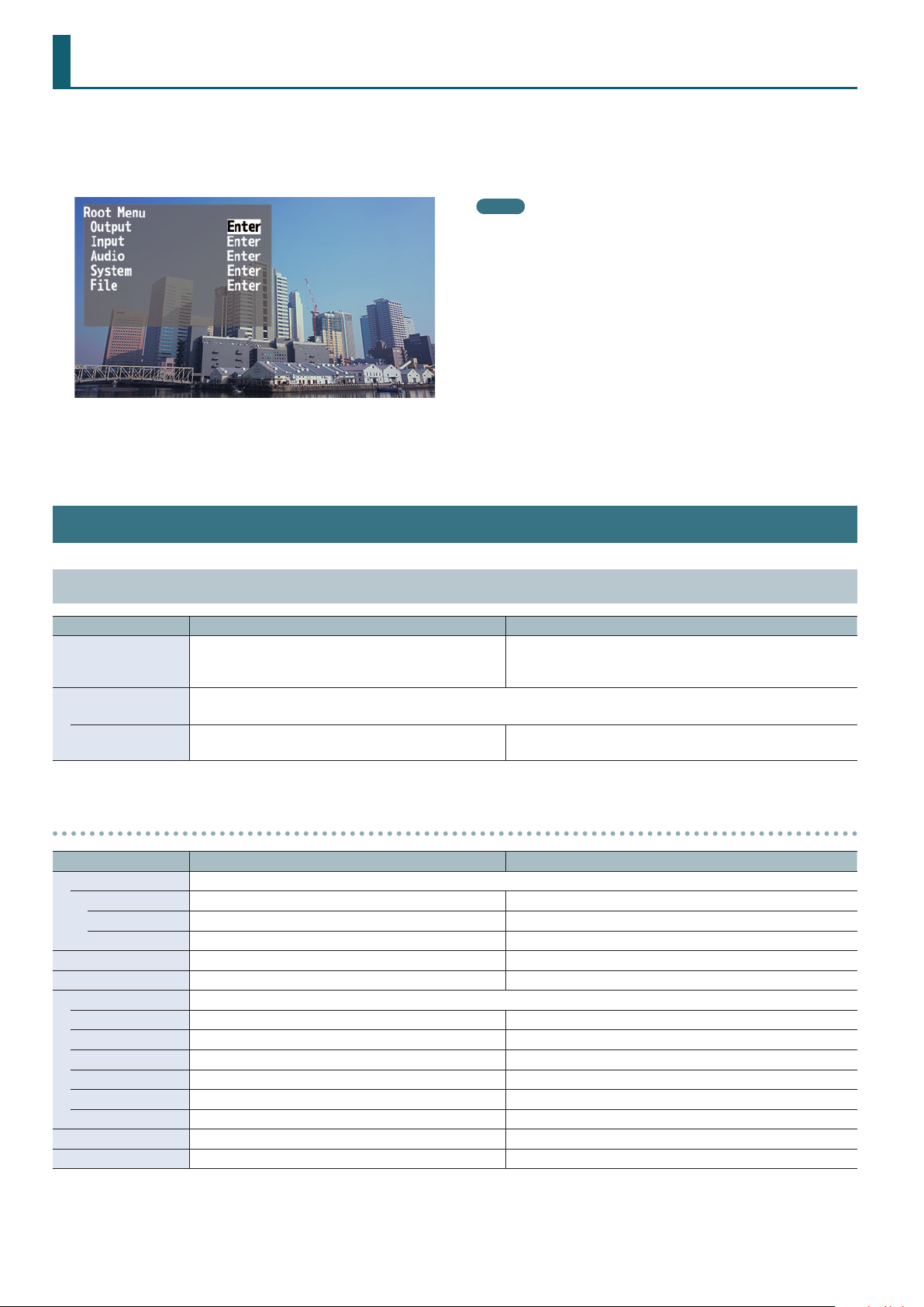
Menu List
When you press the [MENU] button, the menu appears on the monitor that’s connected to the VIDEO OUTPUT 4 connector of the XS-1HD.
* The XS-1HD’s video output provides three screen modes: matrix, split, and switcher (p. 7). The menu that appears depends on the mode.
* The default value is printed in bold characters.
MEMO
5 If the menu extends across multiple pages, you can move in units
of pages by turning the [CURSOR] knob while pressing it.
5 If the value area indicates “Enter,” you can press the [ENTER] button
to proceed to a lower level. Alternatively, pressing the [ENTER]
button executes an operation.
5 By turning the [VALUE] knob while pressing it, you can change the
value more greatly.
5 If you hold down the [ENTER] button and press the [VALUE] knob,
the selected menu item returns to the default setting. If you hold
down the [ENTER] button and long-press the [VALUE] knob, all
menu items in the same level return to the default setting.
Output Menu
In Matrix Mode
Menu item Value Explanation
720p, 1080i, 1080p, 1024 x 768, 1280 x 720, 1280 x 800,
Format
Scaling &
Color Correction
Output 1–4 (Enter)
Output 1–4 detailed settings menu
Menu item Value Explanation
Scaling Use the following settings to specify the scaling.
Zoom 10.0–100.0–1000.0% (*1) Adjusts the zoom ratio.
Size H -1920–0– +1920 (*1) Adjusts the size in the horizontal direction.
Size V -1200–0– +1200 (*1) Adjusts the size in the vertical direction.
Position H -19200–0– +19200 (*1) Adjusts the displayed position in the horizontal direction.
Position V -12000–0– +12000 (*1) Adjusts the displayed position in the vertical direction.
Color Correction Use the following settings to specify color correction.
Brightness -64–0– +64 Adjusts the brightness.
Saturation -64–0– +64 Adjusts the saturation.
Contrast -64–0– +64 Adjusts the contrast.
Red -64–0– +64 Adjusts the red level.
Green -64–0– +64 Adjusts the green level.
Blue -64–0– +64 Adjusts the blue level.
Color Space RGB 0-255, RGB 16-235, YCC Species the color space.
Signal Type HDMI, DVI-D Species the HDMI output mode.
(*1) The range of this value varies according to conditions such as the input/output format. The values listed above are the minimum and maximum values.
1366 x 768, 1280 x 1024, 1400 x 1050, 1600 x 1200,
1920 x 1080, 1920 x 1200
Species scaling settings and color correction for each output.
Species the output format.
Displays a menu for making detailed settings for Output 1–4
(see below).
2
Menu List
In Split Mode or Switcher Mode
Menu item Value Explanation
Species the output format.
720p, 1080i, 1080p, 1024 x 768, 1280 x 720, 1280 x 800,
Format
Scaling (Enter)
Color Correction Species color correction for each output.
Output 1–4 (Enter)
1366 x 768, 1280 x 1024, 1400 x 1050, 1600 x 1200,
1920 x 1080, 1920 x 1200
Scaling detailed settings menu
Menu item Value Explanation
Zoom 10.0–100.0–1000.0% (*2) Adjusts the zoom ratio.
Size H -1920–0– +1920 (*2) Adjusts the size in the horizontal direction.
Size V -1200–0– +1200 (*2) Adjusts the size in the vertical direction.
Position H -19200–0– +19200 (*2) Adjusts the displayed position in the horizontal direction.
Position V -12000–0– +12000 (*2) Adjusts the displayed position in the vertical direction.
(*2) The range of this value varies according to conditions such as the input/output format. The values listed above are the minimum and maximum values.
* In switcher mode, the output format of the VIDEO OUTPUT 4
connector is xed at 1080p/60 Hz. Also, the frame rate of the
video that is output from the VIDEO OUTPUT 4 connector
will decrease to about 5 fps.
Displays a menu for making detailed scaling settings
(see below).
Displays a menu for making detailed settings for Output 1–4
(see below).
Output 1–4 detailed settings menu
Menu item Value Explanation
Color Correction Use the following settings to specify color correction.
Brightness -64–0– +64 Adjusts the brightness.
Saturation -64–0– +64 Adjusts the saturation.
Contrast -64–0– +64 Adjusts the contrast.
Red -64–0– +64 Adjusts the red level.
Green -64–0– +64 Adjusts the green level.
Blue -64–0– +64 Adjusts the blue level.
Color Space RGB 0-255, RGB 16-235, YCC Species the color space.
Signal Type HDMI, DVI-D Species the HDMI output mode.
3

Menu List
Input Menu
Menu item Value Explanation
Input Status (Enter)
Input 1–4 (Enter) Displays a menu for making detailed settings for Input 1–4 (see below).
Background Color (Enter) Displays the background color detailed settings menu (see below).
Input 1–4 detailed settings menu
Menu item Value Explanation
Scaling Use the following settings to specify the scaling.
Zoom 10.0–100.0–1000.0% (*3) Adjusts the zoom ratio.
Type
Manual Size H -1920–0– +1920 (*3) (*4) Adjusts the size in the horizontal direction.
Manual Size V -1200–0– +1200 (*3) (*4) Adjusts the size in the vertical direction.
Position H -19200–0– +19200 (*3) Adjusts the displayed position in the horizontal direction.
Position V -12000–0– +12000 (*3) Adjusts the displayed position in the vertical direction.
Color Correction Use the following settings to specify color correction.
Brightness -64–0– +64 Adjusts the brightness.
Saturation -64–0– +64 Adjusts the saturation.
Contrast -64–0– +64 Adjusts the contrast.
Red -64–0– +64 Adjusts the red level.
Green -64–0– +64 Adjusts the green level.
Blue -64–0– +64 Adjusts the blue level.
Color Space
Flicker Filter Disabled, Enabled Enables/disables the icker lter.
Input Source HDMI, Still Image
(*3) The range of this value varies according to conditions such as the input/output format. The values listed above are the minimum and maximum values.
(*4) Valid when the Scaling “Type” is set to “Manual.”
Full, Letterbox, Crop, Dot by Dot,
Manual
RGB 0-255, RGB 16-235, YCC SD, YCC HD,
Auto
Indicates the video format that is being input to each VIDEO INPUT
connector, and the presence or absence of an HDCP signal.
Species the scaling type.
Full: Regardless of the aspect ratio of the input video, always show
it expanded to the full screen.
Letterbox: Preserving the aspect ratio, expand the input video to match
the horizontal screen resolution. The portion of the video
that falls outside the screen above and below is cut o.
Crop: Preserving the aspect ratio, expand the input video to match
the vertical screen resolution. The portion of the video that
falls outside the screen at left and right is cut o.
Dot by Dot: No scaling is performed.
Manual: Scale according to the “Manual Size H” and “Manual Size V”
settings below.
Species the color space.
Species the source (HDMI input or still image) that is assigned to the input
channel.
Background Color detailed settings menu
Menu item Value Explanation
Hue 0–359 Adjusts the hue.
Saturation 0–255 Adjusts the saturation.
Value 0–255 Adjusts the brightness.
4

Menu List
Composition Menu
In Split Mode
Menu item Value Explanation
XPT 1–4 (Enter)
XPT 1–4 detailed settings menu
Menu item Value Explanation
PinP Window Use the following items to adjust the layer.
Position H -100.0– +100.0% (*5)
Position V -100.0– +100.0% (*5)
Aspect 1:1, 4:3, 3:2, 16:9 Species the aspect ratio.
Size 10.0– +100.0% (*5) Adjusts the size.
Correction H -100.0–0.0– +100.0% Adjusts the size in the horizontal direction.
Correction V -100.0–0.0– +100.0% Adjusts the size in the vertical direction.
PinP View Use the following items to adjust the image that is shown in the layer.
Position H -100.0– +100.0% (*5) Adjusts the displayed position in the horizontal direction.
Position V -100.0–0.0– +100.0% Adjusts the displayed position in the vertical direction.
Zoom 100.0– +1000.0% Adjusts the zoom ratio.
Key (*6) Disabled, Enabled Enables/disables key-compositing.
Type (*6) Luminance Black, Luminance White Species the key-compositing type (color).
Level (*6) 0–127 Adjusts the degree to which the key is removed (transparency).
Gain (*6) 0–16 Adjusts the degree to which the edge of the key is blurred (semi-transparent area).
(*5) Default settings are as follows.
Displays the detailed settings menu for each layer (XPT 1–4) (see below).
Adjusts the displayed position in the
horizontal direction.
Adjusts the displayed position in the vertical
direction.
* The order in which layers are
overlaid is xed.
XPT1
XPT2
XPT3
XPT4
XPT 1 XPT 2 XPT 3 XPT 4
PinP Window
Position H +25.0% -25.0% -50.0% +50.0%
Position V -25.0% -25.0% 0.0% 0.0%
Size 50.0% 40.0% 100.0% 100.0%
PinP View
Position H 0.0% 0.0% +25.0% -25.0%
(*6) Shown only for XPT 1.
5

Menu List
In Switcher Mode
Menu item Value Explanation
Composition Use the following items to make composition settings (PinP, luminance key).
Species whether to use composition or the AUX bus.
PinP & Key: Composite the video using PinP/key. Use the XPT2 row of cross-point
Mode PinP & Key, AUX
AUX: Assign the AUX bus to the VIDEO OUTPUT 3 connector. Use the XPT2 row
Setup (*7) (Enter) Displays the detailed settings menu for composition (see below).
(*7) Shown if the Composition “Mode” is set to “PinP & Key.”
Composition detailed settings menu
Menu item Value Explanation
PinP Window Use the following items to adjust the inset screen.
Position H -100.0– -25.0– +100.0% Adjusts the displayed position in the horizontal direction.
Position V -100.0– -25.0– +100.0% Adjusts the displayed position in the vertical direction.
Aspect 1:1, 4:3, 3:2, 16:9 Species the aspect ratio.
Size 10.0–40.0– +100.0% Adjusts the size.
Correction H -100.0–0.0– +100.0% Adjusts the size in the horizontal direction.
Correction V -100.0–0.0– +100.0% Adjusts the size in the vertical direction.
PinP View Use the following items to adjust the inset screen.
Position H -100.0–0.0– +100.0% Adjusts the displayed position in the horizontal direction.
Position V -100.0–0.0– +100.0% Adjusts the displayed position in the vertical direction.
Zoom 100.0– +1000.0% Adjusts the zoom ratio.
Key Disabled, Enabled Enables/disables key-compositing. The PinP inset screen image is key-composited.
Type Luminance Black, Luminance White Species the key-compositing type (color).
Level 0–127 Adjusts the degree to which the key is removed (transparency).
Gain 0–16 Adjusts the degree to which the edge of the key is blurred (semi-transparent area).
buttons to select the video that you want to composite.
of cross-point buttons to select the video that is sent to the AUX bus.
Audio Menu
Menu item Value Explanation
[Input] HDMI 1–3, HDMI 4/Line/Test Tone
Input HDMI 4, Line, Test Tone
State Mute, Mix, Follow
Level 0–100–127
[Output] All
State Mute, Mix
Level 0–40–127
Follow XPT XPT 1–4
Delay Time 0.0–500.0 ms Adjusts the delay time of the output audio.
(choose from three)
Species the audio source that is assigned to input channel 4.
HDMI 4: The input audio from the VIDEO INPUT 4 connector
Line: The input audio from the AUDIO INPUT connector
Test Tone: Test tone
Species the state of the input channel.
Mute: The input audio is temporarily muted (mute function).
Mix: The audio is input.
Follow: The input channel is used with audio follow.
Adjusts the volume of the input audio.
* 100 = 0.0 dB, and 127 = +6.0 dB.
Species the state of the output channel.
Mute: The output audio is temporarily muted (mute function).
Mix: The result of the audio mix is output.
Adjusts the volume of the output audio.
* 100 = 0.0 dB, and 127 = +6.0 dB.
Species the cross-point buttons that control the audio follow function.
When you use the cross-point buttons specied here to switch video, only the audio
that is used with audio follow is output in tandem with the switched video. Other
audio is automatically muted.
6

System Menu
Menu item Value Explanation
Frame Rate 59.94, 50 Hz Species the frame rate.
HDCP Mode Disabled, Enabled
Screen Mode Matrix, Split, Switcher
XPT Assign (Enter)
Test Pattern (Enter) Displays the test pattern detailed settings menu (p. 8).
EDID Copy (Enter) Displays the EDID copy detailed settings menu (p. 8).
Auto Memory Disabled, Enabled
Auto Power O Disabled, Enabled
Remote Baudrate 9600, 38400 bps Species the communication speed (bps) of the REMOTE connector (RS-232).
LED Dimmer 1–8 Adjusts the brightness of the top panel LEDs.
Fader Calibration (Enter) Calibrates the video fader.
Factory Reset (Enter) Resets the unit to its factory-set state.
Version — Displays the system program version.
If this is set to “Enabled,” copy-protected (HDCP) video can be input. Also, HDCP is applied to
the video that is output.
Species the screen mode of the video output.
Matrix: Use the cross-point buttons to switch the combination of four inputs and four
outputs, and output the video. The internal frame synchronizer allows seamless
video switching.
Split: Up to four screens of the video selected by the crosspoint buttons can be layer-
composited and output. The video of XPT 1 can also be key-composited.
Switcher: The video of the PGM side (XPT3 row) is always output. The PST side (XPT4 row)
selects the preset video (the video that will be output next).
Use the [AUTO] button or operate the video fader to switch the video.
Displays the cross-point assign detailed settings menu (see below).
* When in switcher mode, cross-point assign is only shown.
If this is set to “Enable,” memory 1 functions as the last memory. When you close a menu or
recall a memory, the current settings are automatically saved in memory 1.
Enables/disables the auto-o function.
If this is set to “Enable,” the power automatically turns o when 240 minutes elapse with the
XS-1HD in the following state.
5 The XS-1HD is not operated
5 Audio or video are not input
5 No output device is connected
Menu List
XPT Assign detailed settings menu
In Matrix Mode
Menu item Value Explanation
[Output] [Input]
HDMI 1
HDMI 2
HDMI 3
HDMI 4
O, XPT 1–4
Default settings are as follows.
HDMI 1: XPT 1
HDMI 2: XPT 2
HDMI 3: XPT 3
HDMI 4: XPT 4
In Split Mode
Menu item Value Explanation
[Output] [Input]
HDMI 1 O, XPT 1
HDMI 2 O, XPT 2
HDMI 3 O, XPT 3
HDMI 4 O, XPT 4
Species the cross-point that is assigned to each output. If this is set “O,” video is not output.
5 When using four outputs, video transitions are separated by the background color.
5 By restricting the outputs, you can perform seamless video transitions that use dissolve.
Restrict to three outputs: Seamless video transition is possible for one screen.
Restrict to two outputs: Seamless video transition is possible for two screens simultaneously.
5 By combining cross-points and outputs, 2–4 screens can be spanned.
Enables/disables (O) the cross-point.
5 When compositing four screens, video transitions are separated by the background color.
5 By decreasing the number of screens to three or fewer, you can perform seamless video
transitions using dissolve.
* In split mode, the same image is always output from VIDEO OUTPUT 1–4.
7

Menu List
Test Pattern detailed settings menu
Menu item Value Explanation
Disabled, Color Bars SMPTE, Color Bars 75%,
Pattern
Motion Disabled, Slow, Medium, Fast Species the scroll speed of the test pattern.
Color Bars 100%, Ramp, Step, Hatch, Frame,
Diagonal, Circle, Red, Green, Blue, white, Black
Species the test pattern.
EDID Copy detailed settings menu
Menu item Value Explanation
Species the EDID copy source.
Source Default, Output 1
Destination Input 1–4
Default: The factory-default settings (XS-1HD)
Output 1: The settings of the device connected to VIDEO OUTPUT 1
Species the copy-destination VIDEO INPUT connector.
When you select “Execute” and press the [ENTER] button, the EDID
information is copied.
File Menu
Menu item Value Explanation
All Setting
Load (Enter)
Save (Enter)
Save as (Enter)
Still Image The following item allows you to load a still image.
Load (Enter)
The following items allow you to save the XS-1HD’s settings (the contents of memories 1–16) as a single le on a USB ash
drive. A le saved on a USB ash drive can also be loaded into the XS-1HD.
The File
Select a folder on the USB ash drive and press the [ENTER] button to recall the XS-1HD’s settings.
When you recall the settings, the contents of the XS-1HD’s memories (1–16) are overwritten.
The File
Select a folder on the USB ash drive and press the [ENTER] button to overwrite the settings onto
the settings le (SYSTEM.XS1) in the selected folder.
The File
Saves the XS-1HD’s settings to the USB ash drive as a single le.
When you press the [ENTER] button, a folder is created on the USB ash drive. The XS-1HD’s settings
are saved as a le in the folder that is created.
* If a still image has been loaded into the XS-1HD, the still image is also saved in the folder.
Folder structure
The File
Here you can load a still image from a USB ash drive into the XS-1HD.
File format of the still images that can be loaded
Format Bitmap (.bmp), 24 bits/pixel, uncompressed
Resolution Maximum 1920 x 1200 pixels
File name
Load screen appears.
A
Save screen appears.
A
Save as screen appears.
A
USB ash drive
(a folder name you specify)
SYSTEM.XS1...Internal settings (the contents of memories 1–16)
STILL.XS1...Still image
Load screen appears.
A
Eight or fewer single-byte alphanumeric characters
* The le extension “.bmp” must be added.
Format (Enter) Formats the USB ash drive.
8

RS-232 Command Reference
You can use the REMOTE connector (RS-232) to remotely control the XS-1HD from an external device.
REMOTE Connector (RS-232) Specications
Pin No. Signal
1 2 3 4 5
6 7 8 9
D-sub 9-pin (male)
Communication method
Communication speed 9600, 38400 bps
Parity none
Data length 8 bit
Stop bit 1 bit
Code set ASCII
Flow control XON/XOFF
Synchronous (asynchronous),
full-duplex
1 N.C.
2 RXD
3 TXD
4 DTR
5 GND
6 DSR
7 RTS
8 CTS
9 N.C.
Cable wiring diagram
Connect the three lines RXD, TXD, and GND as shown in the
illustration below.
XS-1HD Controller
N.C.: 1 1:
RXD: 2
TXD: 3 3: TXD
DTR: 4 4:
GND: 5
DSR: 6 6:
RTS: 7 7:
CTS: 8 8:
N.C.: 9 9:
* Numbers 4 and 6, and numbers 7 and 8 are internally
connected inside the XS-1HD.
* Use a cross-cable to make connections with the controlling
device (such as a computer that is equipped with RS-232).
2: RXD
5: GND
Command Summary
The command format consists of the ASCII code string “stx” plus “three alphabetical characters (uppercase)” plus “ ; ” (semicolon).
The three alphabetical characters indicate the type of command.
If the command has an argument, a “ : ” (colon) is inserted between the three alphabetical characters and the argument. If there are multiple
arguments, they are separated by a “ , ” (comma).
stx
:
;
* stx (02H), ACK (06H), and Xon (11H)/Xo (13H) are control codes.
* When the external device transmits successive commands to the XS-1HD, it must wait for “ACK” to be returned before transmitting the next
command.
This is the name of a signal in ASCII code (code number: 02H); it is a control code that indicates the beginning of a command.
“H” indicates hexadecimal notation.
This is the code by which the XS-1HD recognizes the demarcation between the command and the parameter(s).
This is the code by which the XS-1HD recognizes the end of the command.
9

RS-232 Command Reference
Received Commands (Controller0XS-1HD)
Item Received Commands Parameter
Select the XPT1 input (*1) stxXP1:a; a: 0 (Input 1)–3 (Input 4), 4 (Color)
Select the XPT2 input (*1) stxXP2:a; a: 0 (Input 1)–3 (Input 4), 4 (Color)
Select the XPT3 input (*1) stxXP3:a; a: 0 (Input 1)–3 (Input 4), 4 (Color)
Select the XPT4 input (*1) stxXP4:a; a: 0 (Input 1)–3 (Input 4), 4 (Color)
Specify the video transition time stxTIM:a; a: 0 (0.0 sec)–20 (2.0 sec)
Press the [AUTO] button (*2) stxATO;
Adjust the output audio level stxMVL:a; a: 0–127
Adjust the level of audio channel 1 stxCV1:a; a: 0–127
Adjust the level of audio channel 2 stxCV2:a; a: 0–127
Adjust the level of audio channel 3 stxCV3:a; a: 0–127
Adjust the level of audio channel 4 stxCV4:a; a: 0–127
Recall a memory stxMEM:a; a: 0 (Memory 1)–15 (Memory 16)
Return version information stxVER;
Obtain the status of the XS-1HD stxACS;
Flow control XON
Flow control XOFF
(*1) The operation diers depending on the screen mode.
(*2) Valid only when the screen mode is switcher mode.
Sent Commands (XS-1HD0Controller)
Item Sent Commands Parameter
Transmitted when the transmitted
command was received correctly
Transmitted when the transmitted
command was not received correctly
Transmitted when the VER command
is received
Flow control XON
Flow control XOFF
ACK
stxERR:a; a: 0 (syntax error) There is a problem with the received command.
5 (out of range error) The argument of the received command is outside the range.
stxVER:XS-1HD,a; a: Version
* Version information is an ASCII text string
10
02
 Loading...