

Reference Manual
Version 1.5 and later
Contents
Menu List ..................................................... 2
SETUP Menu ...............................................2
AUDIO Menu ...............................................5
RS-232 Command Reference ....................................7
Specication of the RS-232 Connector ........................7
Overview of Commands .....................................7
List of Commands ..........................................8
MIDI Implementation .........................................11
Copyright © 2017 ROLAND CORPORATION
Menu List
* Menus are shown only on the monitor connected to the MULTI-VIEW connector (HDMI).
* The default value is printed in bold characters.
SETUP Menu
Setting item Value Explanation
VIDEO INPUT (page 1/16)
CH3 INPUT SELECT AUTO, SDI, HDMI
CH4 HDMI This adjusts the HDMI input video on channel 4.
SCALING TYPE FULL, LETTERBOX, CROP, DOT BY DOT
H. POSITION -1920–0–1920 This adjusts the display position in the horizontal direction.
V. POSITION -1080–0–1080 This adjusts the display position in the vertical direction.
ZOOM 50–100–200 This adjusts the zoom ratio.
VIDEO INPUT (page 2/16)
CH4 HDMI CONTRAST -64–0–63 This adjusts the contrast.
SATURATION -64–0–63 This adjusts the saturation.
BRIGHTNESS -64–0–63 This adjusts the brightness.
FLICKER FILTER OFF, ON This reduces icker.
EDID
VIDEO OUTPUT (page 3/16)
SDI OUTPUT
HDMI OUTPUT
VIDEO OUTPUT (page 4/16)
COLOR
CORRECTION (*1)
TRANSITION/PinP (page 5/16)
TRANSITION TIME 0.0–1.0–4.0 sec This sets the length of time for applying a video transition.
TRANSITION
PATTERN
PinP/SPLIT
PATTERN
PVW ASSIGN MULTI-VIEW, PST, PGM
3G-SDI MAPPING LEVEL-A, LEVEL-B This sets the mapping structure for 3G-SDI output.
OUTPUT ASSIGN MULTI-VIEW, PST, PGM
COLOR SPACE AUTO, RGB 0-255, RGB 16-235, YCC This sets the color space for HDMI output.
DVI-D/HDMI SIGNAL AUTO, DVI-D, HDMI This sets the output mode for HDMI output.
CONTRAST -64–0–63 This adjusts the contrast of output video.
SATURATION -64–0–63 This adjusts the saturation of output video.
BRIGHTNESS -64–0–63 This adjusts the brightness of output video.
WIPE
MIX MIX, FAM, NAM, MOSAIC This species the transition pattern assigned to the [MIX] button.
PinP
SPLIT
(Pressing and holding the [SETUP] button for 2 seconds or longer)
This species the video source input on channel 3.
AUTO: The connector where the connection is made is automatically
SDI: Video is input only via the SDI IN 3 connector.
HDMI: Video is input only via the HDMI IN 3 connector.
This sets the scaling type.
FULL: This always displays the picture expanded to full screen,
LETTERBOX: This expands the input video to match the horizontal
CROP: This expands the input video to match the vertical
DOT BY DOT: This performs no scaling.
AUTO, 480/576i, 480/576p, 720p, 1080i, 1080p,
640 x 480, 800 x 600, 1024 x 768, 1280 x 768,
1280 x 1024, 1366 x 768, 1400 x 1050, 1600 x 1200,
1920 x 1200
H-DOWN, H-UP, V-RIGHT, V-LEFT, H-IN, H-OUT,
V-IN, V-OUT, R-DOWN, L-DOWN, R-UP, L-UP, BLOCK,
V-GRID, H-GRID, H-DOWN/s, H-UP/s, V-RIGHT/s,
V-LEFT/s, H-IN/s, H-OUT/s, V-IN/s, V-OUT/s,
R-DOWN/s, L-DOWN/s, R-UP/s, L-UP/s, BLOCK/s,
V-GRID/s, H-GRID/s
PinP 1/4, PinP 1/3, PinP 1/2, SPLIT-VS, SPLIT-VC,
SPLIT-HS, SPLIT-HC, QUAD
PinP 1/4, PinP 1/3, PinP 1/2, SPLIT-VS, SPLIT-VC,
SPLIT-HS, SPLIT-HC, QUAD
This sets the EDID value.
This sets the view mode for the preview video output from the PVW
connector (SDI).
This sets the view mode for the preview video output from the MULTIVIEW connector (HDMI).
This species the transition pattern assigned to the [WIPE] button.
* Setting values indicated with “/s” are soft edge transition patterns.
This sets the type of compositing assigned to the [PinP] button.
This sets the type of compositing assigned to the [SPLIT] button.
detected and video is output. When devices are connected to
both the SDI IN 3 connector and the HDMI IN 3 connector, SDI
input takes precedence.
irrespective of the aspect ratio of the input video.
screen resolution while maintaining the aspect ratio.
The protruding picture is cut o at top and bottom.
screen resolution while maintaining the aspect ratio.
The protruding picture is cut o at the left and right.
(*1) These settings are common to both HDMI output (MULTI-PREVIEW connector) and SDI output (PGM and PVW connectors).
2
Menu List
Setting item Value Explanation
TRANSITION/PinP (page 6/16)
PinP BORDER WIDTH 0–3–15 This adjusts the width of the border added to the PinP inset screen.
COLOR BLACK, WHITE, GRAY, RED, GREEN, BLUE, YELLOW This species the color of the border added to the PinP inset screen.
DSK (page 7/16)
DSK OFF, ON This sets DSK composition on or o.
SOURCE CH INPUT1, INPUT2, INPUT3, INPUT4, STILL
KEY TYPE WHT-L.KEY, BLK-L.KEY, GRN-C.KEY, BLU-C.KEY This sets the extraction color for DSK composition.
KEY LEVEL 0–64–255 This adjusts the amount of keying for text and video used in DSK composition.
KEY GAIN 0–255 This adjusts the degree of edge blur for text and video used in DSK composition.
MIX LEVEL 0–255
DSK (page 8/16)
HUE WIDTH -127–0–127 This adjusts the hue width (range).
CHROMA KEY (*2)
PANEL (page 9/16)
PANEL MODE PGM/PST, A/B This sets the operation mode for video transitions.
PGM LED RED, GREEN, YELLOW, BLUE, PURPLE, L.BLUE, WHITE
PST LED RED, GREEN, YELLOW, BLUE, PURPLE, L.BLUE, WHITE
INPUT LED OFF, ON
DSK LED OFF, ON
AUTO LED OFF, ON
AUDIO LED
ALL LED OFF DISABLE, ENABLE
PANEL LOCK (page 10/16)
These set whether panel lock to enabled (ON) or disabled (OFF) for individual buttons and knobs.
ALL SW & VOLUME OFF, ON All controls on menu items for PANEL LOCK (pages 10/16–12/16).
RIGHT SW OFF, ON [DSK], [AUTO] buttons
DSK SW OFF, ON [DSK] button
AUTO SW OFF, ON [AUTO] button
LEFT SW OFF, ON [FREEZE], [MEMORY], [AUDIO] buttons
FREEZE SW OFF, ON [FREEZE] button
MEMORY SW OFF, ON [MEMORY] button
AUDIO SW OFF, ON [AUDIO] button
PANEL LOCK (page 11/16)
These set whether panel lock to enabled (ON) or disabled (OFF) for individual buttons and knobs.
CENTER SW OFF, ON The following buttons
A/B BUS SW OFF, ON [A-1]–[A-4] buttons, [B-1]–[B-4] buttons
KEY LEVEL SW OFF, ON [KEY LEVEL] button
WIPE SW OFF, ON [WIPE] button
MIX SW OFF, ON [MIX] button
CUT SW OFF, ON [CUT] button
PinP SW OFF, ON [PinP] button
SPLIT SW OFF, ON [SPLIT] button
HUE FINE -127–0–127 This adjusts the center position for hue.
SATURATION WIDTH -127–0–127 This adjusts the saturation width (range).
SATURATION FINE 0–255 This adjusts the center position for saturation.
OFF, MASTER OUT, MIC, AUDIO IN, SDI 1, SDI 2,
SDI 3, HDMI 3, HDMI 4
This sets the input channel used for DSK composition.
Setting this to “STILL” performs DSK compositing using a captured still image or
a still image sent from V-1SDI RCS dedicated software.
This adjusts the overall concentration (output level) for text and video used in
DSK composition.
This species the color used when the output video channel buttons ([A-1]–
[A-4], [B-1]–[B-4]) light up.
This species the color used when the buttons for the video channel to output
next ([A-1]–[A-4], [B-1]–[B-4]) light up.
When set to “ON,” the [A-1]–[A-4] and [B-1]–[B-4] buttons light up, ash, and go
dark as shown below.
Button Input video status
Lighted in white Valid video is input.
Flashing in white
Dark No video is input.
Setting this to “ON” makes the [DSK] button light up in red when DSK
composition is on.
Setting this to “ON” makes the [AUTO] button always light up in white. It ashes
in white during video transitions.
This species the audio signal monitored by the AUDIO indicator.
Setting this to “ENABLE” makes all LEDs stay dark at all times, irrespective of the
LED setting for each button.
Video whose format diers from the [FORMAT ] switch
setting is input.
(*2) This is enabled when “KEY TYPE” is “GRN-C.KEY” or “BLU-C.KEY.”
3
Menu List
Setting item Value Explanation
PANEL LOCK (page 12/16)
These set whether panel lock to enabled (ON) or disabled (OFF) for individual knobs and A/B fader.
VOLUME OFF, ON The following knobs and the A/B fader
OUTPUT FADE VOL OFF, ON [OUTPUT FADE] knob
CONTROL 1 VOL OFF, ON [CONTROL 1] knob
CONTROL 2 VOL OFF, ON [CONTROL 2] knob
A/B FADER OFF, ON A/B fader
MEMORY (page 13/16)
MEMORY PANEL LOAD OFF, ON
POWER ON LOAD 1–8
MEMORY PROTECT OFF, ON
AUTO MEMORY OFF, ON
SYSTEM (page 14/16)
HDCP OFF, ON
FRAME RATE 59.94, 50 This sets the frame rate.
FREEZE MODE ALL, SELECT, STILL
DEINTERLACE MODE WEAVE, BOB This species the method used when converting interlaced input video to progressive video.
AUTO OFF OFF, ON
OUTPUT FADE ASSIGN VIDEO, V & A, AUDIO, BLACK / A
SYSTEM (page 15/16)
PVW INDICATOR (*3) LABEL OFF, ON Setting this to “ON” displays labels identifying SDI and HDMI in the preview output.
TALLY OFF, ON Setting this to “ON” displays a tally border in the preview output.
AUDIO LEVEL METER OFF, UPPER, LOWER Setting this to “UPPER” or “LOWER” displays a level meter for audio in the preview output.
AUTO SCAN OFF, ON
SCAN TIME 1–5–120 sec When the Auto Scan function is on, this sets the video display interval.
TRANS TIME 0.0–0.5–4.0 sec When the Auto Scan function is on, this sets the length of time for applying a video transition.
SYSTEM (page 16/16)
COLOR BAR OUTPUT OFF, ON Setting this to “ON” outputs a color bar.
TEST TONE OUTPUT
A/B FADER CALIBRATE — This calibrates the A/B fader.
CAPTURE IMAGE —
RS-232 PANEL STATUS OFF, ON
FACTORY RESET — This returns the unit to its factory defaults.
VERSION — This displays the version of the system program.
OFF, -20 dB@1 kHz,
-6 dB@1 kHz, 0 dB@1 kHz
This sets whether the state of the operation panel is updated to the state saved in memory
(ON) or not updated (OFF) when a memory is recalled.
Selecting a memory number causes the settings at the selected memory number to be
recalled at startup.
Setting this to “ON” protects the memory, making it impossible to saving settings to memory.
* When this is set to “ON,” the AUTO MEMORY feature is disabled.
Setting this to “ON” makes memory 1 function as a last memory. Settings are automatically
saved to memory 1 on exiting the menu or releasing the [MEMORY] button.
When set to “ON,” copyright-protected (HDCP) video can be input. HDCP is also added to the
video that is output.
• “ALL” and “SELECT” specify the operation mode for freezes.
ALL: All video that is input freezes.
SELECT: Input video selected using the [A-1]– [A-4] buttons freezes.
• Setting this to “STILL” makes the [FREEZE] button function as a still-image output button.
This sets the Auto O function on or o.
When set to “ON,” the power to the V-1SDI is automatically turned o if 240 minutes elapse
with no operation performed on the unit.
This species the function of the [OUTPUT FADE] knob.
VIDEO: Applies a fade to the main output video.
V & A: Simultaneously applies a fade to the main output video and adjusts the volume
level of output audio.
AUDIO: Adjusts the volume level of output audio.
BLACK / A: Turning counterclockwise applies a black fade to the main output video. Turning
clockwise adjusts the volume level of output audio.
This sets the Auto Scan function on or o.
When set to “ON,” channels 1 through 4 are switched automatically.
This sets the test tone to output.
You can capture still images from input video on channel 4.
* Either the captured still image or the still image sent from V-1SDI RCS is temporarily stored
in the V-1SDI unit.
If a new still image is captured or is sent from V-1SDI RCS while a still image is already saved,
the previously saved still image is overwritten. Also, still-image data is deleted when the
power is turned o.
Setting this to “ON” always sends a QPL (8: ALL) RS-232 command (p. 10) when switching
channels or switching bus A and bus B.
(*3) This is enabled only for output from the MULTI-VIEW connector (HDMI).
4
Menu List
AUDIO Menu
Setting item Value Explanation
AUDIO LEVEL (page 1/15)
SDI1
:
SDI3
HDMI3
HDMI4
AUDIO
MIC
MASTER OUTPUT LEVEL -INF–0.0–+6.0 dB This adjusts the volume level of output audio.
AUDIO FOLLOW (page 2/15)
A.FOLLOW
AUDIO IN OFF, 1–4
MIC IN OFF, 1–4
AUDIO DELAY (page 3/15)
CH1 SDI
:
CH3 SDI
CH3 HDMI
CH4 HDMI
AUDIO IN
MIC IN
SDI1 IN–SDI3 IN, HDMI3 IN, HDMI4 IN, ADUIO IN (page 4/15–9/15)
EQ Hi -15–0–15 dB This boosts or attenuates the high band.
EQ Hi FREQ 1.00–10.0–20.0 kHz This adjusts the center frequency when changing the sound quality in the high band.
EQ Mid -15–0–15 dB This boosts or attenuates the middle band.
EQ Mid FREQ 20 Hz–500 Hz–20.0 kHz This adjusts the center frequency when changing the sound quality in the middle band.
EQ Mid Q 0.5–16.0 This adjusts the width of the frequency band when boosting or attenuating the middle band.
EQ Lo -15–0–15 dB This boosts or attenuates the low band.
EQ Lo FREQ 20–100–500 Hz This adjusts the center frequency when changing the sound quality in the low band.
MIC IN (page 10/15)
EQ Hi -15–0–15 dB This boosts or attenuates the high band.
EQ Hi FREQ 1.00–10.0–20.0 kHz This adjusts the center frequency when changing the sound quality in the high band.
EQ Mid -15–0–15 dB This boosts or attenuates the middle band.
EQ Mid FREQ 20 Hz–500 Hz–20.0 kHz This adjusts the center frequency when changing the sound quality in the middle band.
EQ Mid Q 0.5–16.0 This adjusts the width of the frequency band when boosting or attenuating the middle band.
EQ Lo -15–0–15 dB This boosts or attenuates the low band.
EQ Lo FREQ 20–100–500 Hz This adjusts the center frequency when changing the sound quality in the low band.
HPF OFF, ON This sets the high-pass lter on or o.
MIC IN (page 11/15)
COMP OFF, ON This sets the compressor on or o.
THRESHOLD -50–-16–0 dB
RATIO 1.0:1–INF:1
ATTAC K 0.2–50–100 ms This sets the time until compression starts when audio exceeding the threshold is input.
RELEASE 30–500–5000 ms This adjusts the length of time until compression ends after audio falls below the threshold.
GATE OFF, ON This sets gate on or o.
THRESHOLD -50–-36–0 dB
RELEASE 30–800–5000 ms This adjusts the length of time until the audio is fully attenuated after audio falls below the threshold.
INPUT LEVEL -INF–0.0–+6.0 dB This adjusts the volume level of the respective input audio streams.
SDI1
:
SDI3
HDMI3
HDMI4
(Pressing and holding the [AUDIO] button for 2 seconds or longer)
OFF, ON
0.0–500.0 ms This adjusts the delay time for audio inputs.
This sets the Audio Follow feature on or o for the respective input video streams.
Setting this to “ON” automatically mutes out audio when the video channel is not selected.
This sets the video channel to interlink by Audio Follow with audio input via AUDIO IN.
Audio input via AUDIO IN is muted on other than the specied video.
This sets the video channel to interlink by Audio Follow with audio input via MIC.
Audio input via MIC is muted on other than the specied video.
This sets the level used as the threshold when compressing audio. Compression is applied to audio
that exceeds the level set here.
This species the degree of compression applied to the audio. The state in which no compression is
applied is dened as “1.”
This sets the level used as the threshold for removing audio. Audio below the level set here is
removed.
5
Menu List
Setting item Value Explanation
AUDIO OUTPUT (page 12/15)
EQ Hi -15–0–15 dB This boosts or attenuates the high band.
EQ Hi FREQ 1.00–10.0–20.0 kHz This adjusts the center frequency when changing the sound quality in the high band.
EQ Mid -15–0–15 dB This boosts or attenuates the middle band.
EQ Mid FREQ 20 Hz–500 Hz–20.0 kHz This adjusts the center frequency when changing the sound quality in the middle band.
EQ Mid Q 0.5–16.0 This adjusts the width of the frequency band when boosting or attenuating the middle band.
EQ Lo -15–0–15 dB This boosts or attenuates the low band.
EQ Lo FREQ 20–100–500 Hz This adjusts the center frequency when changing the sound quality in the low band.
AUDIO OUTPUT (page 13/15)
LEVEL 0–127 This adjusts the return level from reverb of the audio. A setting of “0” results in no reverb applied.
TIME 0.0–1.0–5.0 sec This adjusts the length of the reverb.
REVERB
TYPE ROOM, HALL
AUDIO OUTPUT (page 14/15)
REVERB SEND
LEVEL
AUDIO OUTPUT (page 15/15)
MASTERING OFF, ON This sets the mastering on or o.
NOISE SUPPRESSOR 0–127 This adjusts the degree of application of the noise suppressor.
ENHANCER 0–127 This adjusts the degree of application of the enhancer.
Hi 0–127 This suppresses high-frequency distortion and adjusts the sound to have sustained tones.
Mid 0–127 This suppresses midrange distortion and adjusts the sound to have distinct tones.
Lo 0–127 This suppresses low-frequency distortion and adjusts the sound to have stable tones.
CH1 SDI
:
CH3 SDI
CH3 HDMI
CH4 HDMI
AUDIO IN
MIC IN
0–100–127 This adjusts the send level of audio to Reverb.
This species the type of reverb.
ROOM: Produces the natural reverberations of a highly resonant room.
HALL: Produces reverberations like that of a performance in a concert hall or other such space.
6
RS-232 Command Reference
1 2 3 4 5
6 7 8 9
Using the RS-232 connector, you can operate the V-1SDI remotely from an external device.
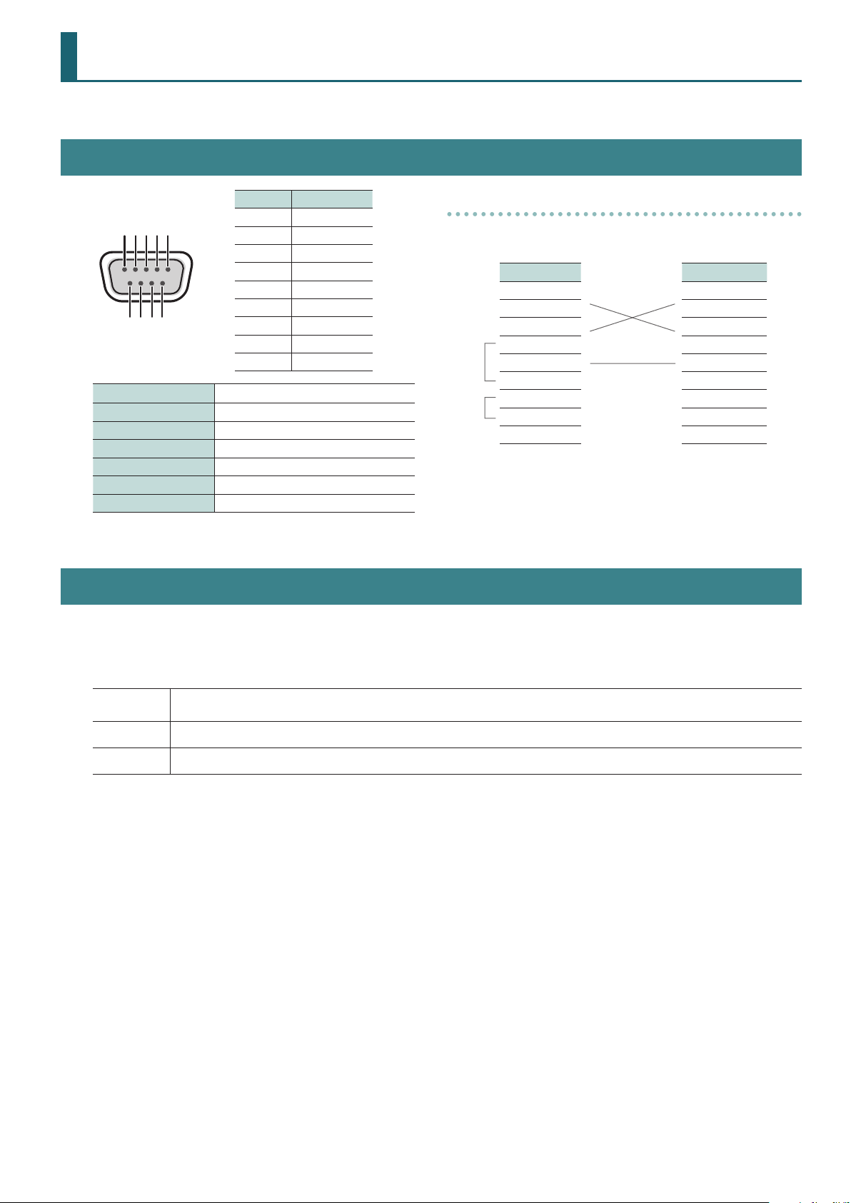
Specification of the RS-232 Connector
Pin No. Signal
1 N.C.
2 RXD
3 TXD
4 DTR
5 GND
6 DSR
D-sub 9-pin (male)
Communication method Synchronous (asynchronous), full-duplex
Communication speed 9600 bps
Parity none
Data length 8 bit
Stop bit 1 bit
Code set ASCII
Flow control XON/XOFF
7 RTS
8 CTS
9 N.C.
Overview of Commands
Cable Wiring Diagram
Wire the three lines of RXD, TXD, and GND as shown in the gure
below.
V-1SDI Controller
N.C.: 1 1:
RXD: 2 2: RXD
TXD: 3 3: TXD
DTR: 4 4:
GND: 5
DSR: 6 6:
RTS: 7 7:
CTS: 8 8:
N.C.: 9 9:
* The connections between 4 and 6 and between 7 and 8 are
inside the V-1SDI.
* When connecting to a controlling device (such as an RS-232
compatible computer), use a crossover cable.
5: GND
Commands are each formatted as an ASCII code string composed of “stx” plus “three alphabetic letters (capitals)” plus “;” (semicolon).
The three letters of the alphabet indicate the type of command.
If the command has an argument, a colon (“:”) is inserted between the command letters and the argument. When multiple arguments occur, they are
separated by commas (“,”).
stx
:
;
* The codes of stx (02H), ACK (06H), and Xon (11H)/ Xo (13H) are the control codes.
* When successively sending commands to the V-1SDI from an external device, after each command, be sure that “ACK” is returned before sending the
next command.
An ASCII-code signal name (code number: 02H), this is a control code indicating the start of a command. “H” indicates that it is a
hexadecimal value.
This is the code that the V-1SDI recognizes as a separator between a command and its argument.
This is the code that the V-1SDI recognizes as the end of a command.
7

RS-232 Command Reference
List of Commands
Video-related Operations
Item
Select bus A channel number stxPGM:a; ACK a: 0 (CH 1)–3 (CH 4)
Select bus B channel number stxPST:a; ACK a: 0 (CH 1)–3 (CH 4)
Specify transition eect stxTRS:a; ACK a: 0 (WIPE), 1 (MIX), 2 (CUT)
Set transition time stxTIM:a; ACK a: 0 (0.0 sec)–40 (4.0 sec)
Press the [AUTO] button stxATO; ACK
Press the [PinP] button stxPIP; ACK
Press the [SPLIT] button stxSPT; ACK
Press the [DSK] button stxDSK; ACK
Press the [FREEZE] button stxFRZ; ACK
Select input connector for INPUT 3 stxIPS:a; ACK a: 0 (AUTO), 1 (SDI 3) ,2 (HDMI 3)
Select scaling type for INPUT 4 stxISC:a; ACK a: 0 (FULL), 1 (LETTERBOX), 2 (CROP), 3 (DOT BY DOT)
Adjust horizontal position of INPUT 4 stxIHP:a; ACK a: -1920–1920
Adjust vertical position of INPUT 4 stxIVP:a; ACK a: -1080–1080
Adjust zoom rasio of INPUT 4 stxIZM:a; ACK a: 50–200
Assign video output of the PVW connector (SDI) stxOPS:a; ACK a: 0 (MULTI-VIEW), 1 (PST), 2 (PGM)
Sent
Commands
Response
Command
Parameter
* Only commands containing a multiple of 8 are accepted.
* Only commands containing a multiple of 8 are accepted.
Assign video output of the MULTI-VIEW connector (HDMI) stxOMS:a; ACK a: 0 (MULTI-VIEW), 1 (PST), 2 (PGM)
Change DSK KEY LEVEL stxKYL:a; ACK a: 0–255
Adjust position of PinP 1/4-size inset screen
* PinP inset screen assigned to the [PinP] button
Adjust position of PinP 1/3-size inset screen
* PinP inset screen assigned to the [PinP] button
Adjust position of PinP 1/2-size inset screen
* PinP inset screen assigned to the [PinP] button
Adjust position of PinP 1/4-size inset screen
* PinP inset screen assigned to the [SPLIT] button
Adjust position of PinP 1/3-size inset screen
* PinP inset screen assigned to the [SPLIT] button
Adjust position of PinP 1/2-size inset screen
* PinP inset screen assigned to the [SPLIT] button
Adjust split-composition “SPLIT-HC” position
* Split-composition video assigned to the [PinP] button
Adjust split-composition “SPLIT-VC” position
* Split-composition video assigned to the [PinP] button
Adjust split-composition “SPLIT-HC” position
* Split-composition video assigned to the [SPLIT] button
stxPQA:a,b; ACK a: 0–255 Horizontal position
b: 0–255 Vertical position
stxPTA:a,b; ACK a: 0–255 Horizontal position
b: 0–255 Vertical position
stxPHA:a,b; ACK a: 0–255 Horizontal position
b: 0–255 Vertical position
stxPQB:a,b; ACK a: 0–255 Horizontal position
b: 0–255 Vertical position
stxPTB:a,b; ACK a: 0–255 Horizontal position
b: 0–255 Vertical position
stxPHB:a,b; ACK a: 0–255 Horizontal position
b: 0–255 Vertical position
stxSHA:a,b; ACK a: 0–255 Vertical position of PGM video (displayed on the left)
b: 0–255 Vertical position of PST video (displayed on the right)
stxSVA:a,b; ACK a: 0–255 Horizontal position of PGM video (displayed above)
b: 0–255 Horizontal position of PST video (displayed below)
stxSHB:a,b; ACK a: 0–255 Vertical position of PGM video (displayed on the left)
b: 0–255 Vertical position of PST video (displayed on the right)
Adjust split-composition “SPLIT-VC” position
* Split-composition video assigned to the [SPLIT] button
Acquire information on input connector selected for INPUT 3 stxQIS; stxQIS:a;
stxSVB:a,b; ACK a: 0–255 Horizontal position of PGM video (displayed above)
ACK
8
b: 0–255 Horizontal position of PST video (displayed below)
a: 0 (SDI), 1 (HDMI)

Audio-related Operations
RS-232 Command Reference
Item
Adjust level of input audio stxIAL:a,b; ACK a: 0 (SDI 1), 1 (SDI 2), 2 (SDI 3), 3 (HDMI 3), 4 (HDMI 4), 5 (AUDIO IN), 6 (MIC IN)
Adjust level of output audio stxOAL:a; ACK a: 0–127
Adjust delay time of input audio stxADT:a,b; ACK a: 0 (SDI 1),1 (SDI 2), 2 (SDI 3), 3 (HDMI 3), 4 (HDMI 4), 5 (AUDIO IN), 6 (MIC IN)
Acquire information on audio level stxQAL:a; stxQAL:b;
Sent
Commands
Response
Command
ACK
Parameter
b: 0–127 * For details, refer to the “Input/Output Level Correspondence Chart” below.
* For details, refer to the “Input/Output Level Correspondence Chart” below.
b: 0 (0.0 ms)–5000 (500.0 ms)
Sent command parameters
a: 0 (SDI 1), 1 (SDI 2), 2 (SDI 3), 3 (HDMI 3), 4 (HDMI 4), 5 (AUDIO IN), 6 (MIC IN), 7 (MASTER OUT), 8 (ALL)
Response command parameters
When a=0, b: 0–127 SDI 1 audio level
When a=1, b: 0–127 SDI 2 audio level
When a=2, b: 0–127 SDI 3 audio level
When a=3, b: 0–127 HDMI 3 audio level
When a=4, b: 0–127 HDMI 4 audio level
When a=5, b: 0–127 AUDIO IN audio level
When a=6, b: 0–127 MIC IN audio level
When a=7, b: 0–127 MASTER OUT
When a=8, sends all audio levels. Example: stxQAL:100,80,70,60,50,40,30,20;
audio level
Input/Output Level Correspondence Chart (Unit: dB)
0 -INF
1 -84.3
2 -68.7
3 -60.2
4 -56.3
5 -53.2
6 -50.1
7 -48.0
8 -46.0
9 -44.0
10 -42.0
11 -40.0
12 -38.0
13 -36.0
14 -34.5
15 -33.0
16 -32.0
17 -31.0
18 -30.0
19 -29.0
20 -28.0
21 -27.2
22 -26.4
23 -25.6
24 -24.8
25 -24.0
26 -23.6
27 -23.2
28 -22.8
29 -22.4
30 -22.0
31 -21.6
32 -21.2
33 -20.8
34 -20.4
35 -20.0
36 -19.6
37 -19.2
38 -18.8
39 -18.4
40 -18.0
41 -17.6
42 -17.2
43 -16.8
44 -16.4
45 -16.0
46 -15.6
47 -15.2
48 -14.8
49 -14.4
50 -14.0
51 -13.6
52 -13.2
53 -12.8
54 -12.4
55 -12.0
56 -11.6
57 -11.3
58 -11.0
59 -10.6
60 -10.3
61 -10.0
62 -9.8
63 -9.5
64 -9.3
65 -9.0
66 -8.8
67 -8.6
68 -8.4
69 -8.2
70 -8.0
71 -7.6
72 -7.3
73 -7.0
74 -6.6
75 -6.3
76 -6.0
77 -5.8
78 -5.5
79 -5.3
80 -5.0
81 -4.8
82 -4.6
83 -4.4
84 -4.2
85 -4.0
86 -3.6
87 -3.3
88 -3.0
89 -2.6
90 -2.3
91 -2.0
92 -1.8
93 -1.5
94 -1.3
95 -1.0
96 -0.8
97 -0.6
98 -0.4
99 -0.2
100 0.0
101 +0.2
102 +0.4
103 +0.6
104 +0.8
105 +1.0
106 +1.3
107 +1.5
108 +1.8
109 +2.0
110 +2.3
111 +2.5
112 +2.8
113 +3.0
114 +3.3
115 +3.5
116 +3.8
117 +4.0
118 +4.2
119 +4.4
120 +4.6
121 +4.8
122 +5.0
123 +5.2
124 +5.4
125 +5.6
126 +5.8
127 +6.0
9

RS-232 Command Reference
System-related Operations
Item
Set HDCP on/o stxHCP:a; ACK a: 0 (OFF), 1 (ON)
Set Auto Scan on/o stxASN:a; ACK a: 0 (OFF) 1 (ON)
Call up memory stxMEM:a; ACK a: 0 (A-1), 1 (A-2), 2 (A-3), 3 (A-4), 4 (B-1), 5 (B-2), 6 (B-3), 7 (B-4)
Acquire status of operation-panel buttons stxQPL:a; stxQPL:b;
Acquire status of V-1SDI stxACS; ACK
Version information stxVER; stxVER:V-1SDI,a; a: Version * The version info is ASCII text strings.
Flow control XON
Sent
Commands
Response
Command
ACK
Parameter
Sent command parameters
a: 0 (PGM), 1 (PST), 2 (PinP), 3 (SPLIT), 4 (DSK), 5 (TRANSITION), 6 (OUTPUT FADE),
7 (A/B fader), 8 (ALL)
Response command parameters
When a=0, b: 0 (CH 1)–3 (CH 4) PGM
When a=1, b: 0 (CH 1)–3 (CH 4) PST
When a=2, b: 0 (OFF), 1 (ON) [PinP] button
When a=3, b: 0 (OFF), 1 (ON) [SPLIT] button
When a=4, b: 0 (OFF), 1 (ON) [DSK] button
When a=5, b: 0 (WIPE), 1 (MIX), 2 (CUT) TRANSITION buttons
When a=6, b: 0–255 Output fade level
0: black, 255: white, 128: center
When a=7, b: 0–255 Output level of A/B fader
0: bus B end, 255: bus A end, 128: center
When a=8, sends all information described above. Example: stxQPL:0,1,0,1,1,0,100,255;
Flow control XOFF
Commands Spontaneously Sent from the V-1SDI
Item
Announce status of operation-panel buttons stxQPL:b; Parameter information is similar to QPL (8: ALL) response.
Error detected stxERR:a; a: 0 (syntax error) The received command contains an error.
Flow control XON
Flow control XOFF
Sent
Commands
Response
Command
Parameter
* This is enabled when the “RS-232 PANEL STATUS” setting under SYSTEM (page 16/16) on
the SETUP menu is set to “ON.”
* This sends the command when the channel is switched or bus A or B is switched.
5 (out of range error) An argument of the received command is out of range.
10

MIDI Implementation
Model: V-1SDI
Date: February 28. 2017
Version: 1.50
Symbol Item Setting Range
n MIDI Channel Fixed at 00H
Control Value,
vv
Velocity Value etc
xx Turning ON/OFF
00H–7FH (0–127)
* If there is a center value, 40H (64) should be the
center.
00H(0): OFF
01H(1): ON
1. MIDI Messages Received at MIDI IN
Channel Voice Messages
z Control Change
{ Bank Select (Controller Number 0, 32)
Status 2nd Byte 3rd Byte
BnH 00H mmH
BnH 20H llH
mm,ll= Bank Number: 00 00H, 01 00H (bus A, bus B)
* This selects one from among video input on bus A, video input on bus B, or a
memory number.
* If unavailable bank select is received, the unit ignores it and receives program
change only.
* The received bank select information is withheld until the unit receives new bank
select.
* Select video input or memory number along with the program change. Control for
bank selects and program changes is as follows.
MSB LSB Program No. Control
00H 00H 00H–03H A ch. INPUT 1–4
01H 00H 00H–03H B ch. INPUT 1–4
50H 00H 00H–07H MEMORY 1–8
{ Panpot (Controller Number 10)
Status 2nd Byte 3rd Byte
BnH 0AH vvH
* This controls the value of the AUDIO MIXER’s SDI 1 audio input level.
{ Expression (Controller Number 11)
Status 2nd Byte 3rd Byte
BnH 0BH vvH
* This controls the value of the AUDIO MIXER’s SDI 2 audio input level.
{ Eect Control 1 (Controller Number 12)
Status 2nd Byte 3rd Byte
BnH 0CH vvH
* This controls the value of the AUDIO MIXER’s SDI 3 audio input level.
{ Eect Control 2 (Controller Number 13)
Status 2nd Byte 3rd Byte
BnH 0DH vvH
* This controls the value of the AUDIO MIXER’s HDMI 3 audio input level.
{ Undened (Controller Number 14)
Status 2nd Byte 3rd Byte
BnH 0EH vvH
* This controls the value of the AUDIO MIXER’s HDMI 4 audio input level.
{ Undened (Controller Number 15)
Status 2nd Byte 3rd Byte
BnH 0FH vvH
* This controls the value of the AUDIO MIXER’s AUDIO IN audio input level.
{ General Purpose Controllers 1 (Controller Number 16)
Status 2nd Byte 3rd Byte
BnH 10H vvH
* This controls the value of the AUDIO MIXER’s MIC audio input level.
{ General Purpose Controllers 2 (Controller Number 17)
Status 2nd Byte 3rd Byte
BnH 11H vvH
* This controls the value of the AUDIO MIXER’s MASTER audio output level.
{ General Purpose Controllers 3 (Controller Number 18)
Status 2nd Byte 3rd Byte
BnH 12H vvH
* This controls the A/B fader.
{ General Purpose Controllers 4 (Controller Number 19)
Status 2nd Byte 3rd Byte
BnH 13H ttH
tt= TRANSITION TIME: 00H–28H (0.0–4.0 sec)
* This controls the value of TRANSITION TIME.
{ Undened (Controller Number 20)
Status 2nd Byte 3rd Byte
BnH 14H ttH
tt= Transition Select: 00H–02H (WIPE, MIX, CUT)
* This controls the type of transition eect.
{ Undened (Controller Number 21)
Status 2nd Byte 3rd Byte
BnH 15H xxH
* This turns the [DSK] button on/o.
{ Undened (Controller Number 22)
Status 2nd Byte 3rd Byte
BnH 16H vvH
* This switches between bus A and bus B.
vvH can be any value (00H–7FH).
{ Undened (Controller Number 23)
Status 2nd Byte 3rd Byte
BnH 17H xxH
* This turns the [KEY LEVEL] button on/o.
{ Undened (Controller Number 24)
Status 2nd Byte 3rd Byte
BnH 18H xxH
* This turns the [PinP] button on/o.
11

MIDI Implementation
{ Undened (Controller Number 25)
Status 2nd Byte 3rd Byte
BnH 19H xxH
* This turns the [SPLIT] button on/o.
{ Undened (Controller Number 26)
Status 2nd Byte 3rd Byte
BnH 1AH vvH
* This controls the state of the [OUTPUT FADE] knob.
{ Undened (Controller Number 27)
Status 2nd Byte 3rd Byte
BnH 1BH xxH
* This turns the [FREEZE] button on/o.
{ Undened (Controller Number 28)
Status 2nd Byte 3rd Byte
BnH 1CH vvH
* This controls the state of the [CONTROL 1] knob.
{ Undened (Controller Number 29)
Status 2nd Byte 3rd Byte
BnH 1DH vvH
* This controls the state of the [CONTROL 2] knob.
z Program Change
Status 2nd Byte
CnH ppH
pp= Program Number: 00H–7FH (1–128)
z Data Request 1 (RQ1)
This is the message to request of “send data” to the connected device. Specify data
type and amount using address and size. When this is received, the unit sends the
requested data as “Data Set 1 (DT1)” message in case the unit is in status where the
sending of data is possible and requested address and size are appropriate. If not, the
unit sends nothing.
Status Data Byte Status
F0H 41H, 10H, 00H, 00H, 00H, 31H, 11H, aaH, F7H
bbH, ccH, ssH, ttH, uuH, sum
Byte Explanation
F0H Exclusive Status
41H Manufacturer ID (Roland)
10H Device ID
00H 1st byte of model ID (V-1SDI)
00H 2nd byte of model ID (V-1SDI)
00H 3rd byte of model ID (V-1SDI)
31H 4th byte of model ID (V-1SDI)
11H Command ID (RQ1)
aaH Address upper byte
bbH Address middle byte
ccH Address lower byte
ssH Size upper byte
ttH Size middle byte
uuH Size lower byte
sum Checksum
F7H EOX (end of exclusive)
* Depending on the data type, the amount of single-time transmission is specied.
It is necessary to execute data request according to the specied rst address and
size. Refer to the “3. Parameter Address Map” (p. 14) for address and size.
* See “Example of an Exclusive Message and Calculating a Checksum” (p. 23) for
checksum.
z Data Set 1 (DT1)
This is the message of actual data transmission. Use this when you want to set data
to the unit.
* Select video input or memory number along with the bank select. For information
on control for bank select and program change, refer to “Bank Select”(p. 11)
* Unselectable program change will be ignored.
System Exclusive Messages
Status Data Byte Status
F0H iiH,ddH,...,eeH F7H
F0H: Status of system exclusive message
ii= ID number: This is the ID to recognize manufacturer of the exclusive
message (manufacturer ID). The manufacturer ID of Roland
is 41H. The ID numbers of 7EH and 7FH are expansion of MID
standards and used as universal non-realtime message (7EH) of
universal realtime message (7FH).
dd,...,ee= data: 00H–7FH (0–127)
F7H: EOX (end of exclusive)
Status Data Byte Status
F0H 41H, 10H, 00H, 00H, 00H, 31H, 12H, aaH, F7H
bbH, ccH, ddH, ..., eeH, sum
Byte Explanation
F0H Exclusive Status
41H Manufacturer ID (Roland)
10H Device ID
00H 1st byte of model ID (V-1SDI)
00H 2nd byte of model ID (V-1SDI)
00H 3rd byte of model ID (V-1SDI)
31H 4th byte of model ID (V-1SDI)
12H Command ID (DT1)
aaH Address upper byte
bbH Address middle byte
ccH Address lower byte
ddH Data: actual data to transmit. Multiple byte data is sent in address order.
: :
eeH Data
sum Checksum
F7H EOX (end of exclusive)
* Depending on the data type, the amount of single-time transmission is specied.
It is necessary to execute data request according to the specied rst address and
size. Refer to the “3. Parameter Address Map” (p. 14) for address and size.
* See “Example of an Exclusive Message and Calculating a Checksum” (p. 23) for
checksum.
* Data exceeding 256 bytes should be divided into packets of 256 bytes or smaller. If
you send data set 1 successively, set interval of 20 ms or longer between packets.
12

2. MIDI Messages Transmitted from
MIDI OUT
Channel Voice Messages
z Control Change
{ Bank Select (Controller Number 0, 32)
Status 2nd Byte 3rd Byte
BnH 00H mmH
BnH 20H llH
mm, ll= Bank Number: 00 00H, 01 00H (bank.1, bank.2)
* When a video input or memory number has been selected, this transmits a bank
number along with a program change. Control for bank selects and program
changes is as follows.
MSB LSB Program No. Control
00H 00H 00H–03H A ch. INPUT 1–4
01H 00H 00H–03H B ch. INPUT 1–4
50H 00H 00H–07H MEMORY 1–8
MIDI Implementation
{ General Purpose Controllers 2 (Controller Number 17)
Status 2nd Byte 3rd Byte
BnH 11H vvH
* This transmits the value when the AUDIO MIXER’s MASTER audio output level has
been changed.
{ General Purpose Controllers 3 (Controller Number 18)
Status 2nd Byte 3rd Byte
BnH 12H vvH
* This transmits the value when the A/B fader has been controlled.
{ General Purpose Controllers 4 (Controller Number 19)
Status 2nd Byte 3rd Byte
BnH 13H ttH
tt= TRANSITION TIME: 00H–28H (0.0–4.0 sec)
* This transmits the value when TRANSITION TIME has been changed.
{ Undened (Controller Number 20)
Status 2nd Byte 3rd Byte
BnH 14H ttH
{ Panpot (Controller Number 10)
Status 2nd Byte 3rd Byte
BnH 0AH vvH
* This transmits the value when the AUDIO MIXER’s SDI 1 audio input level has been
changed.
{ Expression (Controller Number 11)
Status 2nd Byte 3rd Byte
BnH 0BH vvH
* This transmits the value when the AUDIO MIXER’s SDI 2 audio input level has been
changed.
{ Eect Control 1 (Controller Number 12)
Status 2nd Byte 3rd Byte
BnH 0CH vvH
* This transmits the value when the AUDIO MIXER’s SDI 3 audio input level has been
changed.
{ Eect Control 2 (Controller Number 13)
Status 2nd Byte 3rd Byte
BnH 0DH vvH
* This transmits the value when the AUDIO MIXER’s HDMI 3 audio input level has
been changed.
{ Undened (Controller Number 14)
Status 2nd Byte 3rd Byte
BnH 0EH vvH
* This transmits the value when the AUDIO MIXER’s HDMI 4 audio input level has
been changed
{ Undened (Controller Number 15)
Status 2nd Byte 3rd Byte
BnH 0FH vvH
* This transmits the value when the AUDIO MIXER’s AUDIO IN audio input level has
been changed.
{ General Purpose Controllers 1 (Controller Number 16)
Status 2nd Byte 3rd Byte
BnH 10H vvH
* This transmits the value when the AUDIO MIXER’s MIC audio input level has been
changed.
tt= Transition Select: 00H–02H (WIPE, MIX, CUT)
* This transmits the value when the [WIPE], [MIX], or [CUT] button has been operated.
{ Undened (Controller Number 21)
Status 2nd Byte 3rd Byte
BnH 15H xxH
* This transmits the value when [DSK] button has been operated.
{ Undened (Controller Number 22)
Status 2nd Byte 3rd Byte
BnH 16H vvH
* This transmits the value when the [AUTO] button has been operated.
{ Undened (Controller Number 23)
Status 2nd Byte 3rd Byte
BnH 17H xxH
* This transmits the value when the [KEY LEVEL] button has been operated.
{ Undened (Controller Number 24)
Status 2nd Byte 3rd Byte
BnH 18H xxH
* This transmits the value when the [PinP] button has been operated.
{ Undened (Controller Number 25)
Status 2nd Byte 3rd Byte
BnH 19H xxH
* This transmits the value when the [SPLIT] button has been operated.
{ Undened (Controller Number 26)
Status 2nd Byte 3rd Byte
BnH 1AH vvH
* This transmits the value when the [OUTPUT FADE] knob has been operated.
{ Undened (Controller Number 27)
Status 2nd Byte 3rd Byte
BnH 1BH xxH
* This transmits the value when the [FREEZE] button has been operated.
13

MIDI Implementation
{ Undened (Controller Number 28)
Status 2nd Byte 3rd Byte
BnH 1CH vvH
* This transmits the value when the [CONTROL 1] knob has been operated.
{ Undened (Controller Number 29)
Status 2nd Byte 3rd Byte
BnH 1DH vvH
* This transmits the value when the [CONTROL 2] knob has been operated.
z Program Change
Status 2nd Byte
CnH ppH
pp= Program Number: 00H–7FH (1–128)
* When a video input or memory number has been selected, this transmits a
program number along with a bank select. For information on control for bank
select and program change, refer to “Bank Select” (p. 13).
System Exclusive Message
Status Data Byte Status
F0H iiH,ddH,...,eeH F7H
F0H: Status of system exclusive message
ii= ID number: This is the ID to recognize manufacturer of the exclusive
message (manufacturer ID). The manufacturer ID of Roland
is 41H. The ID numbers of 7EH and 7FH are expansion of MID
standards and used as universal non-realtime message (7EH) of
universal realtime message (7FH).
dd,...,ee= data: 00H–7FH (0–127)
F7H: EOX (end of exclusive)
z Data Set 1 (DT1)
This is the message of actual data transmission. Use this when you want to set data
to the unit.
Status Data Byte Status
F0H 41H, 10H, 00H, 00H, 00H, 31H, 12H, aaH, F7H
bbH, ccH, ddH, ..., eeH, sum
Byte Explanation
F0H Exclusive Status
41H Manufacturer ID (Roland)
10H Device ID
00H 1st byte of model ID (V-1SDI)
00H 2nd byte of model ID (V-1SDI)
00H 3rd byte of model ID (V-1SDI)
31H 4th byte of model ID (V-1SDI)
12H Command ID (DT1)
aaH Address upper byte
bbH Address middle byte
ccH Address lower byte
ddH Data: actual data to transmit. Multiple byte data is sent in address order.
: :
eeH Data
sum Checksum
F7H EOX (end of exclusive)
* Data exceeding 256 bytes should be divided into packets of 256 bytes or smaller. If
you send sequentially, the intervals of packets should be longer than 20 ms.
14

MIDI Implementation
3. Parameter Address Map
* At addresses with “#” appended, the specied data is transmitted divided into the upper 2 bytes and lower 2 bytes. The data is ignored if the 2-byte sets are not received in
succession.
Start Address Description
00H 00H 00H Reserved
70H 00H 00H System Parameter Area
71H 00H 00H Video, Audio, Panel Parameter Area
72H 00H 00H Video, Audio, Panel Parameter Memory Area
73H 00H 00H Reserved
73H 01H 00H Other Parameter Area
74H 00H 00H Reserved
z System Parameter Area
{ Products, version, mode
Address Parameter Name Sys.Ex.Value Meaning of Value
70H 00H 00H System Version String (1) 00H–7FH ASCII Character (Read Only)
70H 00H 01H System Version String (2) 00H–7FH ASCII Character (Read Only)
70H 00H 02H System Version String (3) 00H–7FH ASCII Character (Read Only)
70H 00H 03H System Version String (4) 00H–7FH ASCII Character (Read Only)
70H 00H 04H System Version String (5) 00H–7FH ASCII Character (Read Only)
70H 00H 05H System Version String (6) 00H–7FH ASCII Character (Read Only)
70H 00H 06H System Version String (7) 00H–7FH ASCII Character (Read Only)
70H 00H 07H System Version String (8) 00H–7FH ASCII Character (Read Only)
70H 00H 08H System Version String (9) 00H–7FH ASCII Character (Read Only)
70H 00H 09H Reserved
70H 00H 10H System Device Mode 00H 00H: NORMAL (Read Only)
{ Setup Parameter
Address Parameter Name Sys.Ex.Value Meaning of Value
70H 01H 00H PANEL MODE 00H–01H A/B, PGM/PST
70H 01H 01H PGM LED 00H–06H RED, GREEN, YELLOW, BLUE, PURPLE, L.BLUE, WHITE
70H 01H 02H PST LED 00H–06H RED, GREEN, YELLOW, BLUE, PURPLE, L.BLUE, WHITE
70H 01H 03H INPUT LED 00H–01H OFF, ON
70H 01H 04H DSK LED 00H–01H OFF, ON
70H 01H 05H AUTO LED 00H–01H OFF, ON
70H 01H 06H AUDIO LED 00H–08H OFF, MASTER OUT, MIC, AUDIO IN, SDI 1, SDI 2, SDI 3, HDMI 3, HDMI 4
70H 01H 07H ALL LED OFF 00H–01H DISABLE, ENABLE
70H 01H 08H LOCK DSK SW 00H–01H OFF, ON
70H 01H 09H LOCK AUTO SW 00H–01H OFF, ON
70H 01H 0AH LOCK FREEZE SW 00H–01H OFF, ON
70H 01H 0BH LOCK MEMORY SW 00H–01H OFF, ON
70H 01H 0CH LOCK AUDIO SW 00H–01H OFF, ON
70H 01H 0DH LOCK A/B BUS SW 00H–01H OFF, ON
70H 01H 0EH LOCK KEY LEVEL SW 00H–01H OFF, ON
70H 01H 0FH LOCK WIPE SW 00H–01H OFF, ON
70H 01H 10H LOCK MIX SW 00H–01H OFF, ON
70H 01H 11H LOCK CUT SW 00H–01H OFF, ON
70H 01H 12H LOCK PinP SW 00H–01H OFF, ON
70H 01H 13H LOCK SPLIT SW 00H–01H OFF, ON
70H 01H 14H LOCK OUTPUT FADE VOL 00H–01H OFF, ON
70H 01H 15H LOCK CONTROL 1 VOL 00H–01H OFF, ON
70H 01H 16H LOCK CONTROL 2 VOL 00H–01H OFF, ON
70H 01H 17H LOCK A/B FADER 00H–01H OFF, ON
70H 01H 18H MEMORY PANEL LOAD 00H–01H OFF, ON
70H 01H 19H POWER ON LOAD 00H–07H Memory 1–Memory 8
70H 01H 1AH MEMORY PROTECT 00H–01H OFF, ON
70H 01H 1BH AUTO MEMORY 00H–01H OFF, ON
70H 01H 1CH HDCP 00H–01H OFF, ON
70H 01H 1DH FRAME RATE 00H–01H 59.94, 50
15

MIDI Implementation
Address Parameter Name Sys.Ex.Value Meaning of Value
70H 01H 1EH FREEZE MODE 00H–02H ALL, SELECT, STILL
70H 01H 1FH DEINTERLACE MODE 00H–01H WEAVE, BOB
70H 01H 20H AUTO OFF 00H–01H OFF, ON
70H 01H 21H OUTPUT FADER ASSIGN 00H–03H VIDEO, V & A, AUDIO, BLACK / A
70H 01H 22H PVW INDICATER LABEL 00H–01H OFF, ON
70H 01H 23H PVW INDICATER TALLY 00H–01H OFF, ON
70H 01H 24H PVW INDICATER AUDIO 00H–02H OFF, UPPER, LOWER
70H 01H 25H AUTO SCAN ON/OFF 00H–01H OFF, ON
70H 01H 26H AUTO SCAN TIME 01H–78H 1–120 sec
70H 01H 27H AUTO SCAN TRANS TIME 00H–28H 0.0–4.0 sec
70H 01H 28H COLOR BAR OUTPUT 00H–01H OFF, ON
70H 01H 29H TEST TONE OUTPUT 00H–03H OFF, -20 dB@1 kHz, -6 dB@1 kHz, 0 dB@1 kHz
70H 01H 2AH RS-232 PANEL STATUS 00H–01H OFF, ON
70H 01H 2BH FREEZE SELECT CH 00H–03H CH-1–CH-4
z Video/Audio/Panel Parameter Area
{ Video, Audio, Panel Parameter Area
These modify current operation.
Address Parameter Name
71H 00H 00H Video
71H 01H 00H Audio Parameter-1
71H 02H 00H Audio Parameter-2
71H 03H 00H Panel Parameter
{ Video, Audio, Panel Parameter Memory Area
These read or overwrite data saved at memory numbers other than the one currently selected. Data saved at the currently selected memory is not modied.
* The parameters in “ Video Parameter” (p. 16), “Audio Parameter-1” (p. 17), “Audio Parameter-2” (p. 18) and “Panel Parameter” (p. 20) are also common to the video,
audio and panel parameter memory area.
Address Parameter Name Address Parameter Name
72H 00H 00H Video (Memory 1) 72H 10H 00H Video (Memory 5)
72H 01H 00H Audio Parameter-1 (Memory 1) 72H 11H 00H Audio Parameter-1 (Memory 5)
72H 02H 00H Audio Parameter-2 (Memory 1) 72H 12H 00H Audio Parameter-2 (Memory 5)
72H 03H 00H Panel (Memory 1) 72H 13H 00H Panel (Memory 5)
72H 04H 00H Video (Memory 2) 72H 14H 00H Video (Memory 6)
72H 05H 00H Audio Parameter-1 (Memory 2) 72H 15H 00H Audio Parameter-1 (Memory 6)
72H 06H 00H Audio Parameter-2 (Memory 2) 72H 16H 00H Audio Parameter-2 (Memory 6)
72H 07H 00H Panel (Memory 2) 72H 17H 00H Panel (Memory 6)
72H 08H 00H Video (Memory 3) 72H 18H 00H Video (Memory 7)
72H 09H 00H Audio Parameter-1 (Memory 3) 72H 19H 00H Audio Parameter-1 (Memory 7)
72H 0AH 00H Audio Parameter-2 (Memory 3) 72H 1AH 00H Audio Parameter-2 (Memory 7)
72H 0BH 00H Panel (Memory 3) 72H 1BH 00H Panel (Memory 7)
72H 0CH 00H Video (Memory 4) 72H 1CH 00H Video (Memory 8)
72H 0DH 00H Audio Parameter-1 (Memory 4) 72H 1DH 00H Audio Parameter-1 (Memory 8)
72H 0EH 00H Audio Parameter-2 (Memory 4) 72H 1EH 00H Audio Parameter-2 (Memory 8)
72H 0FH 00H Panel (Memory 4) 72H 1FH 00H Panel (Memory 8)
{ Video Parameter
Address Parameter Name Sys.Ex.Value Meaning of Value
71H 00H 00H CH3 INPUT SELECT 00H–02H AUTO, SDI, HDMI
71H 00H 01H CH4 HDMI SCALING TYPE 00H–03H FULL, LETTERBOX, CROP, DOT BY DOT
#71H 00H 02H
03H
#71H 00H 04H
05H
#71H 00H 06H
07H
71H 00H 08H CH4 HDMI CONTRAST 00H–7FH -64–63
71H 00H 09H CH4 HDMI SATURATION 00H–7FH -64–63
71H 00H 0AH CH4 HDMI BRIGHTNESS 00H–7FH -64–63
71H 00H 0BH CH4 HDMI FLICKER FILTER 00H–01H OFF, ON
CH4 HDMI H. POSITION 00H 00H–1EH 00H
CH4 HDMI V. POSITION 00H 00H–10H 70H
CH4 HDMI ZOOM 00H 32H–01H 48H 50–200
-1920–1920
* Only values that are multiples of 8 can be specied.
-1080–1080
* Only values that are multiples of 8 can be specied.
16

MIDI Implementation
Address Parameter Name Sys.Ex.Value Meaning of Value
AUTO, 480/576i, 480/576p, 720p, 1080i, 1080p, 640x480, 800x600,
71H 00H 0CH CH4 HDMI EDID 00H–0EH
71H 00H 0DH Reserved
71H 00H 0EH SDI PVW ASSIGN 00H–02H MULTI-VIEW, PST, PGM
71H 00H 0FH 3G-SDI MAPPING 00H–01H LEVEL A, LEVEL B
71H 00H 10H HDMI PVW ASSIGN 00H–02H MULTI-VIEW, PST, PGM
71H 00H 11H HDMI OUT COLOR SPACE 00H–03H AUTO, RGB 0-255, RGB 16-235, YCC
71H 00H 12H DVI-D/HDMI SIGNAL 00H–02H AUTO, DVI-D, HDMI
71H 00H 13H VIDEO OUT CONTRAST 00H–7FH -64–63
71H 00H 14H VIDEO OUT SATURATION 00H–7FH -64–63
71H 00H 15H VIDEO OUT BRIGHTNESS 00H–7FH -64–63
71H 00H 16H Reserved
71H 00H 17H TRANSITION TIME 00H–28H 0.0–4.0 sec
71H 00H 18H WIPE PAT TERN 00H–1DH
71H 00H 19H MIX PAT TERN 00H–03H MIX, FAM, NAM, MOSAIC
71H 00H 1AH PinP PAT TERN 00H–07H PinP 1/4, PinP 1/3, PinP 1/2, SPLIT-VS, SPLIT-VC, SPLIT-HS, SPLIT-HC, QUAD
71H 00H 1BH SPLIT PATTERN 00H–07H PinP 1/4, PinP 1/3, PinP 1/2, SPLIT-VS, SPLIT-VC, SPLIT-HS, SPLIT-HC, QUAD
71H 00H 1CH PinP BORDER WIDTH 00H–0FH 0–15
71H 00H 1DH PinP BORDER COLOR 00H–06H BLACK, WHITE, GRAY, RED, GREEN, BLUE, YELLOW
71H 00H 1EH Reserved
71H 00H 1FH DSK ON/OFF 00H–01H OFF, ON
71H 00H 20H DSK SOURCE CH 00H–04H INPUT1, INPUT2, INPUT3, INPUT4, STILL
71H 00H 21H KEY TYPE 00H–03H WHT-L.KEY, BLK-L.KEY, GRN-C.KEY, BLU-C.KEY
#71H 00H 22H
23H
#71H 00H 24H
25H
#71H 00H 26H
27H
#71H 00H 28H
29H
#71H 00H 2AH
2BH
#71H 00H 2CH
2DH
#71H 00H 2EH
2FH
KEY LEVEL 00H 00H–01H 7FH 0–255
KEY GAIN 00H 00H–01H 7FH 0–255
MIX LEVEL 00H 00H–01H 7FH 0–255
HUE WIDTH 00H 00H–01H 7FH -128–127
HUE FINE 00H 00H–01H 7FH -128–127
SATURATION WIDTH 00H 00H–01H 7FH -128–127
SATURATION FINE 00H 00H–01H 7FH 0–255
1024x768, 1280x768, 1280x1024, 1366x768, 1400x1050, 1600x1200,
1920x1200
H-DOWN, H-UP, V-RIGHT, V-LEFT, H-IN, H-OUT, V-IN, V-OUT, R-DOWN,
L-DOWN, R-UP, L-UP, BLOCK, V-GRID, H-GRID, H-DOWN/s, H-UP/s,
V-RIGHT/s, V-LEFT/s, H-IN/s, H-OUT/s, V-IN/s, V-OUT/s, -DOWN/s,
L-DOWN/s, R-UP/s, L-UP/s, BLOCK/s, V-GRID/s, H-GRID/s
{ Audio Parameter-1
Address Parameter Name Sys.Ex.Value Meaning of Value
71H 01H 00H SDI1 INPUT LEVEL 00H–7FH -INF–+6.0 dB
71H 01H 01H SDI2 INPUT LEVEL 00H–7FH -INF–+6.0 dB
71H 01H 02H SDI3 INPUT LEVEL 00H–7FH -INF–+6.0 dB
71H 01H 03H HDMI3 INPUT LEVEL 00H–7FH -INF–+6.0 dB
71H 01H 04H HDMI4 INPUT LEVEL 00H–7FH -INF–+6.0 dB
71H 01H 05H AUDIO INPUT LEVEL 00H–7FH -INF–+6.0 dB
71H 01H 06H MIC INPUT LEVEL 00H–7FH -INF–+6.0 dB
71H 01H 07H MASTER OUT LEVEL 00H–7FH -INF–+6.0 dB
71H 01H 08H A. FOLLOW SDI1 00H–01H OFF, ON
71H 01H 09H A. FOLLOW SDI2 00H–01H OFF, ON
71H 01H 0AH A. FOLLOW SDI3 00H–01H OFF, ON
71H 01H 0BH A. FOLLOW HDMI3 00H–01H OFF, ON
71H 01H 0CH A. FOLLOW HDMI4 00H–01H OFF, ON
71H 01H 0DH A. FOLLOW AUDIO IN 00H–04H OFF, 1–4
71H 01H 0EH A. FOLLOW MIC IN 00H–04H OFF, 1–4
71H 01H 0FH Reserved
#71H 01H 10H
11H
DELAY SDI1 00H 00H–27H 08H 0.0–500.0 ms
17

MIDI Implementation
Address Parameter Name Sys.Ex.Value Meaning of Value
#71H 01H 12H
13H
#71H 01H 14H
15H
#71H 01H 16H
17H
#71H 01H 18H
19H
#71H 01H 1AH
1BH
#71H 01H 1CH
1DH
71H 01H 1EH Reserved
71H 01H 1FH Reserved
71H 01H 20H SDI1 IN EQ Hi 00H–1EH -15–15 dB
71H 01H 21H SDI1 IN EQ Hi FREQ 44H–78H 1.00–20.0 kHz
71H 01H 22H SDI1 IN EQ Mid 00H–1EH -15–15 dB
71H 01H 23H SDI1 IN EQ Mid FREQ 00H–78H 20 Hz–20.0 kHz
71H 01H 24H SDI1 IN EQ Mid Q 00H–05H 0.5–16.0
71H 01H 25H SDI1 IN EQ Lo 00H–1EH -15–15 dB
71H 01H 26H SDI1 IN EQ Lo FREQ 00H–38H 20–500 Hz
71H 01H 27H Reserved
71H 01H 28H SDI2 IN EQ Hi 00H–1EH -15–15 dB
71H 01H 29H SDI2 IN EQ Hi FREQ 44H–78H 1.00–20.0 kHz
71H 01H 2AH SDI2 IN EQ Mid 00H–1EH -15–15 dB
71H 01H 2BH SDI2 IN EQ Mid FREQ 00H–78H 20 Hz–20.0 kHz
71H 01H 2CH SDI2 IN EQ Mid Q 00H–05H 0.5–16.0
71H 01H 2DH SDI2 IN EQ Lo 00H–1EH -15–15 dB
71H 01H 2EH SDI2 IN EQ Lo FREQ 00H–38H 20–500 Hz
71H 01H 2FH Reserved
71H 01H 30H SDI3 IN EQ Hi 00H–1EH -15–15 dB
71H 01H 31H SDI3 IN EQ Hi FREQ 44H–78H 1.00–20.0 kHz
71H 01H 32H SDI3 IN EQ Mid 00H–1EH -15–15 dB
71H 01H 33H SDI3 IN EQ Mid FREQ 00H–78H 20 Hz–20.0 kHz
71H 01H 34H SDI3 IN EQ Mid Q 00H–05H 0.5–16.0
71H 01H 35H SDI3 IN EQ Lo 00H–1EH -15–15 dB
71H 01H 36H SDI3 IN EQ Lo FREQ 00H–38H 20–500 Hz
71H 01H 37H Reserved
71H 01H 38H HDMI3 IN EQ Hi 00H–1EH -15–15 dB
71H 01H 39H HDMI3 IN EQ Hi FREQ 44H–78H 1.00–20.0 kH
71H 01H 3AH HDMI3 IN EQ Mid 00H–1EH -15–15 dB
71H 01H 3BH HDMI3 IN EQ Mid FREQ 00H–78H 20 Hz–20.0 kHz
71H 01H 3CH HDMI3 IN EQ Mid Q 00H–05H 0.5–16.0
71H 01H 3DH HDMI3 IN EQ Lo 00H–1EH -15–15 dB
71H 01H 3EH HDMI3 IN EQ Lo FREQ 00H–38H 20–500 Hz
71H 01H 3FH Reserved
71H 01H 40H HDMI4 IN EQ Hi 00H–1EH -15–15 dB
71H 01H 41H HDMI4 IN EQ Hi FREQ 44H–78H 1.00–20.0 kHz
71H 01H 42H HDMI4 IN EQ Mid 00H–1EH -15–15 dB
71H 01H 43H HDMI4 IN EQ Mid FREQ 00H–78H 20 Hz–20.0 kHz
71H 01H 44H HDMI4 IN EQ Mid Q 00H–05H 0.5–16.0
71H 01H 45H HDMI4 IN EQ Lo 00H–1EH -15–15 dB
71H 01H 46H HDMI4 IN EQ Lo FREQ 00H–38H 20–500 Hz
DELAY SDI2 00H 00H–27H 08H 0.0–500.0 ms
DELAY SDI3 00H 00H–27H 08H 0.0–500.0 ms
DELAY HDMI3 00H 00H–27H 08H 0.0–500.0 ms
DELAY HDMI4 00H 00H–27H 08H 0.0–500.0 ms
DELAY AUDIO IN 00H 00H–27H 08H 0.0–500.0 ms
DELAY MIC IN 00H 00H–27H 08H 0.0–500.0 ms
18

{ Audio Parameter-2
Address Parameter Name Sys.Ex.Value Meaning of Value
71H 02H 00H AUDIO IN EQ Hi 00H–1EH -15–15 dB
71H 02H 01H AUDIO IN EQ Hi FREQ 44H–78H 1.00–20.0 kHz
71H 02H 02H AUDIO IN EQ Mid 00H–1EH -15–15 dB
71H 02H 03H AUDIO IN EQ Mid FREQ 00H–78H 20 Hz–20.0 kHz
71H 02H 04H AUDIO IN EQ Mid Q 00H–05H 0.5–16.0
71H 02H 05H AUDIO IN EQ Lo 00H–1EH -15–15 dB
71H 02H 06H AUDIO IN EQ Lo FREQ 00H–38H 20–500 Hz
71H 02H 07H Reserved
71H 02H 08H MIC IN EQ Hi 00H–1EH -15–15 dB
71H 02H 09H MIC IN EQ Hi FREQ 44H–78H 1.00–20.0 kHz
71H 02H 0AH MIC IN EQ Mid 00H–1EH -15–15 dB
71H 02H 0BH MIC IN EQ Mid FREQ 00H–78H 20 Hz–20.0 kHz
71H 02H 0CH MIC IN EQ Mid Q 00H–05H 0.5–16.0
71H 02H 0DH MIC IN EQ Lo 00H–1EH -15–15 dB
71H 02H 0EH MIC IN EQ Lo FREQ 00H–38H 20–500 Hz
71H 02H 0FH MIC IN HPF 00H–01H OFF, ON
71H 02H 10H MIC IN COMP 00H–01H OFF, ON
71H 02H 11H MIC IN COMP THRESHOLD 00H–32H -50–0 dB
71H 02H 12H MIC IN COMP RATIO 00H–08H 1.0:1 – INF:1
71H 02H 13H MIC IN COMP ATTACK 00H–19H 0.2–100 ms
71H 02H 14H MIC IN COMP RELEASE 00H–7FH 30–5000 ms
71H 02H 15H MIC IN GATE 00H–01H OFF, ON
71H 02H 16H MIC IN GATE THRESHOLD 00H–32H -50–0 dB
71H 02H 17H MIC IN GATE RELEASE 00H–7FH 30–5000 ms
71H 02H 18H MASTER OUT EQ Hi 00H–1EH -15–15 dB
71H 02H 19H MASTER OUT EQ Hi FREQ 44H–78H 1.00–20.0 kHz
71H 02H 1AH MASTER OUT EQ Mid 00H–1EH -15–15 dB
71H 02H 1BH MASTER OUT EQ Mid FREQ 00H–78H 20 Hz–20.0 kHz
71H 02H 1CH MASTER OUT EQ Mid Q 00H–05H 0.5–16.0
71H 02H 1DH MASTER OUT EQ Lo 00H–1EH -15–15 dB
71H 02H 1EH MASTER OUT EQ Lo FREQ 00H–38H 20–500 Hz
71H 02H 1FH Reserved
71H 02H 20H REVERB LEVEL 00H–7FH 0–127
71H 02H 21H REVERB TIME 00H–32H 0.0–5.0 sec
71H 02H 22H REVERB TYPE 00H–01H ROOM, HALL
71H 02H 23H REVERB SEND LEVEL SDI1 00H–7FH 0–127
71H 02H 24H REVERB SEND LEVEL SDI2 00H–7FH 0–127
71H 02H 25H REVERB SEND LEVEL SDI3 00H–7FH 0–127
71H 02H 26H REVERB SEND LEVEL HDMI3 00H–7FH 0–127
71H 02H 27H REVERB SEND LEVEL HDMI4 00H–7FH 0–127
71H 02H 28H REVERB SEND LEVEL AUDIO IN 00H–7FH 0–127
71H 02H 29H REVERB SEND LEVEL MIC IN 00H–7FH 0–127
71H 02H 2AH MASTERING 00H–01H OFF, ON
71H 02H 2BH MASTERING NOISE SUPPRESSOR 00H–7FH 0–127
71H 02H 2CH MASTERING ENHANSER 00H–7FH 0–127
71H 02H 2DH MASTERING Hi 00H–7FH 0–127
71H 02H 2EH MASTERING Mid 00H–7FH 0–127
71H 02H 2FH MASTERING Lo 00H–7FH 0–127
MIDI Implementation
19

MIDI Implementation
{ Panel Parameter
Address Parameter Name Sys.Ex.Value Meaning of Value
#71H 03H 00H
01H
#71H 03H 02H
03H
#71H 03H 04H
05H
#71H 03H 06H
07H
71H 03H 08H VIDEO SEL A 00H–03H Input 1–4
71H 03H 09H VIDEO SEL B 00H–03H Input 1–4
71H 03H 0AH [PinP] 00H–01H [PinP] button OFF, ON
71H 03H 0BH [SPLIT] 00H–01H [SPLIT ] button OFF, ON
71H 03H 0CH TRANSITION PATTERN 00H–02H WIPE, MIX, CUT
71H 03H 0DH [DSK] 00H–01H [DSK] button OFF, ON
71H 03H 0EH [KEY LEVEL] 00H–01H [KEY LEVEL] button OFF, ON
71H 03H 0FH A/B FADER START POSITION 00H–01H 00H: bus A end, 01H: bus B end
#71H 03H 10H
11H
#71H 03H 12H
13H
#71H 03H 14H
15H
#71H 03H 16H
17H
#71H 03H 18H
19H
#71H 03H 1AH
1BH
#71H 03H 1CH
1DH
#71H 03H 1EH
1FH
#71H 03H 20H
21H
#71H 03H 22H
23H
#71H 03H 24H
25H
#71H 03H 26H
27H
#71H 03H 28H
29H
#71H 03H 2AH
2BH
#71H 03H 2CH
2DH
#71H 03H 2EH
2FH
#71H 03H 30H
31H
#71H 03H 32H
33H
#71H 03H 34H
35H
#71H 03H 36H
37H
A/B FADER 00H 00H–07H 7F 0–1023
CONTROL 1 VOL 00H 00H–01H 7FH 0–255
CONTROL 2 VOL 00H 00H–01H 7FH 0–255
OUTPUT FADER 00H 00H–01H 7FH 0–255
PinP 1/4 CONTROL 1 VOL
(PinP SW)
PinP 1/4 CONTROL 2 VOL
(PinP SW)
PinP 1/2 CONTROL 1 VOL
(PinP SW)
PinP 1/2 CONTROL 2 VOL
(PinP SW)
SPLIT VC CONTROL 1 VOL
(PinP SW)
SPLIT VC CONTROL 2 VOL
(PinP SW)
SPLIT HC CONTROL 1 VOL
(PinP SW)
SPLIT HC CONTROL 2 VOL
(PinP SW)
PinP 1/4 CONTROL 1 VOL
(SPLIT SW)
PinP 1/4 CONTROL 2 VOL
(SPLIT SW)
PinP 1/2 CONTROL 1 VOL
(SPLIT SW)
PinP 1/2 CONTROL 2 VOL
(SPLIT SW)
SPLIT VC CONTROL 1 VOL
(SPLIT SW)
SPLIT VC CONTROL 2VOL
(SPLIT SW)
SPLIT HC CONTROL 1 VOL
(SPLIT SW)
SPLIT HC CONTROL 2 VOL
(SPLIT SW)
PinP 1/3 CONTROL 1VOL
(PinP SW)
PinP 1/3 CONTROL 2VOL
(PinP SW)
PinP 1/3 CONTROL 1VOL
(SPLIT SW)
PinP 1/3 CONTROL 2VOL
(SPLIT SW)
00H 00H–01H 7FH 0–255
00H 00H–01H 7FH 0–255
00H 00H–01H 7FH 0–255
00H 00H–01H 7FH 0–255
00H 00H–01H 7FH 0–255
00H 00H–01H 7FH 0–255
00H 00H–01H 7FH 0–255
00H 00H–01H 7FH 0–255
00H 00H–01H 7FH 0–255
00H 00H–01H 7FH 0–255
00H 00H–01H 7FH 0–255
00H 00H–01H 7FH 0–255
00H 00H–01H 7FH 0–255
00H 00H–01H 7FH 0–255
00H 00H–01H 7FH 0–255
00H 00H–01H 7FH 0–255
00H 00H–01H 7FH 0–255
00H 00H–01H 7FH 0–255
00H 00H–01H 7FH 0–255
00H 00H–01H 7FH 0–255
20

MIDI Implementation
z Other Parameter Area
{ MEMORY
Address Parameter Name Sys.Ex.Value Meaning of Value
73H 01H 00H MEMORY SELECT 00H–07H MEMORY 1–8
MEMORY SAVE 10H–17H MEMORY 1–8
MEMORY INIT 20H–28H This returns MEMORY 1–8 (20H–27H) and Current (28H) to default values.
* Sending 1nH or 2nH changes the memory selection to the specied memory.
* Even if 1nH or 2nH is specied, RQ1 results in sending of 00H–07H (the currently selected memory).
{ LED
Address Parameter Name Sys.Ex.Value Meaning of Value
73H 02H 00H LED OUTFADER BLACK 00H–01H OFF, GREEN (Read Only)
73H 02H 01H LED OUTFADER WHITE 00H–01H OFF, GREEN (Read Only)
73H 02H 02H LED FREEZE 00H–01H OFF, RED (Read Only)
73H 02H 03H LED MEMORY 00H–01H OFF, BLUE (Read Only)
73H 02H 04H LED AUDIO 00H–03H OFF, RED, GREEN, YELLOW (Read Only)
73H 02H 05H LED PEKSIG 00H–03H OFF, RED, GREEN, YELLOW (Read Only)
73H 02H 06H LED SETUP 00H–01H OFF, GREEN (Read Only)
73H 02H 07H LED PANELLOCK 00H–01H OFF, RED (Read Only)
73H 02H 08H LED PINP 00H–01H OFF, GREEN (Read Only)
73H 02H 09H LED SPLIT 00H–01H OFF, GREEN (Read Only)
73H 02H 0AH LED HDCP 00H–01H OFF, RED (Read Only)
73H 02H 0BH LED KEYLEVEL 00H–01H OFF, RED (Read Only)
73H 02H 0CH LED WIPE 00H–01H OFF, GREEN (Read Only)
73H 02H 0DH LED MIX 00H–01H OFF, GREEN (Read Only)
73H 02H 0EH LED CUT 00H–01H OFF, GREEN (Read Only)
73H 02H 0FH LED DSK 00H–07H OFF, RED, GREEN, YELLOW, BLUE, MAZENTA, CYAN, WHITE (Read Only)
73H 02H 10H LED AUTO 00H–07H OFF, RED, GREEN, YELLOW, BLUE, MAZENTA, CYAN, WHITE (Read Only)
73H 02H 11H LED VDOSEL1A 00H–07H OFF, RED, GREEN, YELLOW, BLUE, MAZENTA, CYAN, WHITE (Read Only)
73H 02H 12H LED VDOSEL2A 00H–07H OFF, RED, GREEN, YELLOW, BLUE, MAZENTA, CYAN, WHITE (Read Only)
73H 02H 13H LED VDOSEL3A 00H–07H OFF, RED, GREEN, YELLOW, BLUE, MAZENTA, CYAN, WHITE (Read Only)
73H 02H 14H LED VDOSEL4A 00H–07H OFF, RED, GREEN, YELLOW, BLUE, MAZENTA, CYAN, WHITE (Read Only)
73H 02H 15H LED VDOSEL1B 00H–07H OFF, RED, GREEN, YELLOW, BLUE, MAZENTA, CYAN, WHITE (Read Only)
73H 02H 16H LED VDOSEL2B 00H–07H OFF, RED, GREEN, YELLOW, BLUE, MAZENTA, CYAN, WHITE (Read Only)
73H 02H 17H LED VDOSEL3B 00H–07H OFF, RED, GREEN, YELLOW, BLUE, MAZENTA, CYAN, WHITE (Read Only)
73H 02H 18H LED VDOSEL4B 00H–07H OFF, RED, GREEN, YELLOW, BLUE, MAZENTA, CYAN, WHITE (Read Only)
{ AUDIO LEVEL METER
Address Parameter Name Sys.Ex.Value Meaning of Value
73H 03H 00H AUDIO LEVEL METER MASTER L 00H–33H -INF, -50–0 dB (Read Only)
73H 03H 01H AUDIO LEVEL METER MASTER R 00H–33H -INF, -50–0 dB (Read Only)
73H 03H 02H AUDIO LEVEL METER SDI1 L 00H–33H -INF, -50–0 dB (Read Only)
73H 03H 03H AUDIO LEVEL METER SDI1 R 00H–33H -INF, -50–0 dB (Read Only)
73H 03H 04H AUDIO LEVEL METER SDI2 L 00H–33H -INF, -50–0 dB (Read Only)
73H 03H 05H AUDIO LEVEL METER SDI2 R 00H–33H -INF, -50–0 dB (Read Only)
73H 03H 06H AUDIO LEVEL METER SDI3 L 00H–33H -INF, -50–0 dB (Read Only)
73H 03H 07H AUDIO LEVEL METER SDI3 R 00H–33H -INF, -50–0 dB (Read Only)
73H 03H 08H AUDIO LEVEL METER HDMI3 L 00H–33H -INF, -50–0 dB (Read Only)
73H 03H 09H AUDIO LEVEL METER HDMI3 R 00H–33H -INF, -50–0 dB (Read Only)
73H 03H 0AH AUDIO LEVEL METER HDMI4 L 00H–33H -INF, -50–0 dB (Read Only)
73H 03H 0BH AUDIO LEVEL METER HDMI4 R 00H–33H -INF, -50–0 dB (Read Only)
73H 03H 0CH AUDIO LEVEL METER LINE L 00H–33H -INF, -50–0 dB (Read Only)
73H 03H 0DH AUDIO LEVEL METER LINE R 00H–33H -INF, -50–0 dB (Read Only)
73H 03H 0EH AUDIO LEVEL METER MIC L 00H–33H -INF, -50–0 dB (Read Only)
73H 03H 0FH AUDIO LEVEL METER MIC R 00H–33H -INF, -50–0 dB (Read Only)
21

MIDI Implementation
{ CTRL BUTTON
Address Parameter Name Sys.Ex.Value Meaning of Value
73H 04H 00H [FREEZE] 00H, 20H, 40H [FREEZE] button on/long press/o
[MEMORY] 01H, 21H, 41H [MEMORY] button on/long press/o
[AUDIO] 02H, 22H, 42H [AUDIO] button on/long press/o
[SETUP] 03H, 23H, 43H [SETUP] button on/long press/o
[PinP] 04H, 24H, 44H [PinP] button on/long press/o
[SPLIT] 05H, 25H, 45H [SPLIT] button on/long press/o
[VIDEO SELECT 1A] 06H, 26H, 46H [ VIDEO SELECT 1A] button on/long press/o
[VIDEO SELECT 2A] 07H, 27H, 47H [ VIDEO SELECT 2A] button on/long press/o
[VIDEO SELECT 3A] 08H, 28H, 48H [ VIDEO SELECT 3A] button on/long press/o
[VIDEO SELECT 4A] 09H, 29H, 49H [ VIDEO SELECT 4A] button on/long press/o
[VIDEO SELECT 1B] 0AH, 2AH, 4AH [VIDEO SELECT 1B] button on/long press/o
[VIDEO SELECT 2B] 0BH, 2BH, 4BH [VIDEO SELECT 2B] button on/long press/o
[VIDEO SELECT 3B] 0CH, 2CH, 4CH [ VIDEO SELECT 3B] button on/long press/o
[VIDEO SELECT 4B] 0DH, 2DH, 4DH [VIDEO SELECT 4B] button on/long press/o
[KEY LEVEL] 0EH, 2EH, 4EH [KEY LEVEL] button on/long press/o
[WIPE] 0FH, 2FH, 4FH [ WIPE] button on/long press/o
[MIX] 10H, 30H, 50H [MIX] button on/long press/o
[CUT] 11H, 31H, 51H [CUT] button on/long press/o
[DSK] 12H, 32H, 52H [DSK] button on/long press/o
[AUTO] 13H, 33H, 53H [AUTO] button on/long press/o
22

MIDI Implementation
4. Supplementary Material
z Decimal and Hexadecimal Table
(Hexadecimal Numbers are Indicated by ‘H’)
In MIDI documentation, data values and addresses/sizes of exclusive messages etc.
are expressed as hexadecimal values for each 7 bits.
The following table shows how these correspond to decimal numbers.
+——————+——————++——————+——————++——————+——————++——————+——————+
| D | H || D | H || D | H || D | H |
+——————+——————++——————+——————++——————+——————++——————+——————+
| 0 | 00H || 32 | 20H || 64 | 40H || 96 | 60H |
| 1 | 01H || 33 | 21H || 65 | 41H || 97 | 61H |
| 2 | 02H || 34 | 22H || 66 | 42H || 98 | 62H |
| 3 | 03H || 35 | 23H || 67 | 43H || 99 | 63H |
| 4 | 04H || 36 | 24H || 68 | 44H || 100 | 64H |
| 5 | 05H || 37 | 25H || 69 | 45H || 101 | 65H |
| 6 | 06H || 38 | 26H || 70 | 46H || 102 | 66H |
| 7 | 07H || 39 | 27H || 71 | 47H || 103 | 67H |
| 8 | 08H || 40 | 28H || 72 | 48H || 104 | 68H |
| 9 | 09H || 41 | 29H || 73 | 49H || 105 | 69H |
| 10 | 0AH || 42 | 2AH || 74 | 4AH || 106 | 6AH |
| 11 | 0BH || 43 | 2BH || 75 | 4BH || 107 | 6BH |
| 12 | 0CH || 44 | 2CH || 76 | 4CH || 108 | 6CH |
| 13 | 0DH || 45 | 2DH || 77 | 4DH || 109 | 6DH |
| 14 | 0EH || 46 | 2EH || 78 | 4EH || 110 | 6EH |
| 15 | 0FH || 47 | 2FH || 79 | 4FH || 111 | 6FH |
| 16 | 10H || 48 | 30H || 80 | 50H || 112 | 70H |
| 17 | 11H || 49 | 31H || 81 | 51H || 113 | 71H |
| 18 | 12H || 50 | 32H || 82 | 52H || 114 | 72H |
| 19 | 13H || 51 | 33H || 83 | 53H || 115 | 73H |
| 20 | 14H || 52 | 34H || 84 | 54H || 116 | 74H |
| 21 | 15H || 53 | 35H || 85 | 55H || 117 | 75H |
| 22 | 16H || 54 | 36H || 86 | 56H || 118 | 76H |
| 23 | 17H || 55 | 37H || 87 | 57H || 119 | 77H |
| 24 | 18H || 56 | 38H || 88 | 58H || 120 | 78H |
| 25 | 19H || 57 | 39H || 89 | 59H || 121 | 79H |
| 26 | 1AH || 58 | 3AH || 90 | 5AH || 122 | 7AH |
| 27 | 1BH || 59 | 3BH || 91 | 5BH || 123 | 7BH |
| 28 | 1CH || 60 | 3CH || 92 | 5CH || 124 | 7CH |
| 29 | 1DH || 61 | 3DH || 93 | 5DH || 125 | 7DH |
| 30 | 1EH || 62 | 3EH || 94 | 5EH || 126 | 7EH |
| 31 | 1FH || 63 | 3FH || 95 | 5FH || 127 | 7FH |
+——————+——————++——————+——————++——————+——————++——————+——————+
D: decimal
H: hexadecimal
* Decimal expressions used for MIDI channel, bank select, and program change are 1
greater than the decimal value shown in the above table.
* Hexadecimal values in 7-bit units can express a maximum of 128 levels in one byte
of data. If the data requires greater resolution, two or more bytes are used. For
example, a value indicated by a hexadecimal expression in two 7-bit bytes aa bbH
would be aa x 128 + bb.
* In the case of values which have a ± sign, 00H = -64, 40H = ±0, and 7FH = +63, so
that the decimal expression would be 64 less than the value given in the above
chart. In the case of two types, 00 00H = -8192, 40 00H = ±0, and 7F 7FH = +8191.
For example if aa bbH were expressed as decimal, this would be aa bbH - 40 00H =
aa x 128 + bb - 64 x 128.
* Data marked “nibbled” is expressed in hexadecimal in 4-bit units. A value expressed
as a 2-byte nibble 0a 0bH has the value of a x 16 + b.
<Example1>
What is the decimal expression of 5AH?
From the preceding table, 5AH = 90
<Example2>
What is the decimal expression of the value 12 34H given as hexadecimal for each 7
bits?
From the preceding table, since 12H = 18 and 34H = 52
18 x 128 + 52 = 2356
<Example3>
What is the decimal expression of the nibbled value 0A 03 09 0D?
From the preceding table, since 0AH = 10, 03H = 3, 09H = 9, 0DH = 13
((10 x 16 + 3) x 16 + 9) x 16 + 13 = 41885
<Example4>
What is the nibbled expression of the decimal value 1258?
16) 1258
16) 78... 10
16) 4... 14
0... 4
Since from the preceding table, 0 = 00H, 4 = 04H, 14 = 0EH, 10 = 0AH, the answer is
00 04 0E 0AH.
z MIDI Message Examples
<Example 1> 92H 3EH 5FH
9n is a note on status and n is the MIDI channel number.
As 2H = 2, 3EH = 62 and 5FH = 95, this is a note on message of MIDI CH =3 , note
number 62 (D4) and velocity 95.
<Example 2> CEH 49H
CnH is program change status, and n is the MIDI channel number.
As EH = 14 and 49H = 73, this is a program change message of MIDI CH = 15 and
program number 74 (in the GS sound map, Flute).
z Example of an Exclusive Message and Calculating a
Checksum
Roland Exclusive messages are transmitted with a checksum at the end (before F7)
to make sure that the message was correctly received. The value of the checksum is
determined by the address and data (or size) of the transmitted exclusive message.
{ How to Calculate the Checksum
(Hexadecimal Numbers are Indicated by ‘H’)
The checksum is a value that produces a lower 7 bits of zero when the address, size,
and checksum itself are summed. If the exclusive message to be transmitted has an
address of aa bb ccH and the data is dd ee H, the actual calculation would be as
follows:
aa + bb + cc + dd + ee + = sum
sum / 128 = quotient ... remainder
128 - remainder = checksum
(However, the checksum will be 0 if the remainder is 0.)
<Example>
Setting Dissolve Time Ctrl Assign in MIDI Visual Control to Modulation for Control
Changes
From the “Parameter Address Map,” the start address of the Dissolve Time Ctrl Assign
in MIDI Visual Control is 10H 10H 02H and the Modulation parameter in Control
Change is 00H 01H. Therefore ...
F0H 7EH 00H 0CH 01H 10H 10H 02H 00H 01H ??H F7H
(1) (2) (3) (4) (5) (6) (7) (8)
(1) Exclusive Status
(2) ID Number (Universal SysEx Non Realtime)
(3) Device ID (0)
(4) Sub ID (MIDI Visual Control Version 1.0)
(5) Address
(6) Data
(7) Checksum
(8) EOX
Next calculate the checksum. Add (5) to (6).
10H + 10H + 02H + 00H + 01H = 16 + 16 + 2 + 0 + 1 = 35 (sum)
35 (sum) / 128 = 0 (quotient) ... 35 (remainder)
Checksum = 128 - 35 (remainder) = 93 = 5DH
Thus, the message to transmit is :
F0H 7EH 00H 0CH 01H 10H 10H 02H 00H 01H 5DH F7H
23

3G-SDI Video Switcher
Model V-1SDI
Function Transmitted Recognized Remarks
Basic
Channel
Mode
Note
Number
Velocity
After
Touch
Pitch Bend × × Controls various parameters
Default
Unchanged
Default
Messages
Altered
True Voice × ×
Note On
Note O
Key’s
Channel’s
MIDI Implementation Chart
0, 32
1–9
10–29
30–119
×
1
×
×
**************
×
×
×
×
O
×
O
×
×
1
×
×
**************
×
×
×
× Controls various parameters
O
×
O
×
Saved when power o
Controls various parameters
Date: Feb. 28, 2017
Version: 1.50
Control
Change
Program
Change : True Number
System Exclusive O O
System
Common
System
Real Time
Aux
Messages
: Song Position
: Song Select
: Tune Request
: Clock
: Commands
: All Sound O
: Reset All Controllers
: Local On/O
: All Notes O
: Active Sensing
: System Reset
O
0–127
×
×
×
×
×
×
×
×
×
×
×
O
0–127
×
×
×
×
×
×
×
×
×
×
×
Channel select
Notes
Mode 1 : OMNI ON, POLY Mode 2 : OMNI ON, MONO
Mode 3 : OMNI OFF, POLY Mode 4 : OMNI OFF, MONO
24
O : Yes
X : No

25

* Roland is either registered trademark or trademark of Roland Corporation in the United States and/or other countries.
02
 Loading...