

Page 1
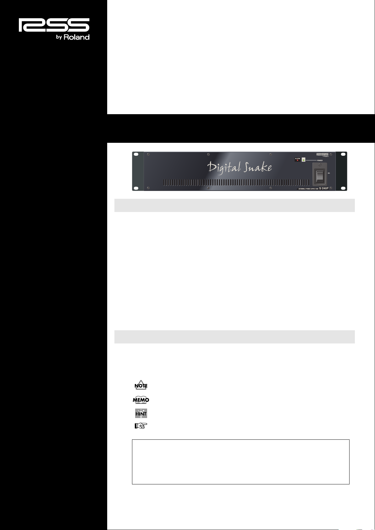
S-240P Owner’s Manual
Contents
USING THE UNIT SAFELY ........................................................................................ 3
Important Notes ......................................................................................................... 5
Panel Descriptions .................................................................................................... 6
Using the S-240P ....................................................................................................... 7
About the S-240P .................................................................................................... 7
Installation Notes .....................................................................................................7
S-4000 series Connections...................................................................................... 8
Powering Up/System Status Indicators ................................................................... 9
Information............................................................................................................... 10
Appendices .............................................................................................................. 11
Troubleshooting ..................................................................................................... 11
Connector Information ...........................................................................................11
Specification .......................................................................................................... 11
Dimensions ............................................................................................................ 12
Note, Memo, Hint and Reference Icons
Throughout the RSS S-240P External Power Supply Unit Owner’s Manual, you’ll
occasionally come to areas that provide extra information related to the feature or
operation described in the main text. The symbols define the nature of this extra
information.
A warning contains important information that will help you avoid damage to the S-4000
System, other equipment, or yourself.
A note is something that adds information about the topic at hand.
A tip offers suggestions for using the feature being discussed.
Indicates a reference page.
Before using this unit, carefully read the sections entitled: “IMPORTANT SAFETY
INSTRUCTIONS” (p. 2), “USING THE UNIT SAFELY” (p. 3–4), and “IMPORTANT NOTES”
(p. 5). These sections provide important information concerning the proper operation of the
unit. Additionally, in order to feel assured that you have gained a good grasp of every feature
provided by your new unit, the S-240P Owner’s Manual should be read in its entirety. The
manual should be saved and kept on hand as a convenient reference.
Copyright © 2006 ROLAND CORPORATION
All rights reserved. No part of this publication may be reproduced in any form
without the written permission of ROLAND CORPORATION.
Page 2
IMPORTANT SAFETY INSTRUCTIONS
CAUTION
RISK OF ELECTRIC SHOCK
DO NOT OPEN
ATTENTION: RISQUE DE CHOC ELECTRIQUE NE PAS OUVRIR
CAUTION: TO REDUCE THE RISK OF ELECTRIC SHOCK,
DO NOT REMOVE COVER (OR BACK).
NO USER-SERVICEABLE PARTS INSIDE.
REFER SERVICING TO QUALIFIED SERVICE PERSONNEL.
The lightning flash with arrowhead symbol, within an
equilateral triangle, is intended to alert the user to the
presence of uninsulated “dangerous voltage” within the
product’s enclosure that may be of sufficient magnitude to
constitute a risk of electric shock to persons.
The exclamation point within an equilateral triangle is
intended to alert the user to the presence of important
operating and maintenance (servicing) instructions in the
literature accompanying the product.
INSTRUCTIONS PERTAINING TO A RISK OF FIRE, ELECTRIC SHOCK, OR INJURY TO PERSONS.
IMPORTANT SAFETY INSTRUCTIONS
SAVE THESE INSTRUCTIONS
WARNING - When using electric products, basic precautions should always be followed, including the following:
1. Read these instructions.
2. Keep these instructions.
3. Heed all warnings.
4. Follow all instructions.
5. Do not use this apparatus near water.
6. Clean only with a dry cloth.
7. Do not block any of the ventilation openings. Install in
accordance with the manufacturers instructions.
8. Do not install near any heat sources such as radiators,
heat registers, stoves, or other apparatus (including
amplifiers) that produce heat.
9. Do not defeat the safety purpose of the polarized or
grounding-type plug. A polarized plug has two blades with
one wider than the other. A grounding type plug has two
blades and a third grounding prong. The wide blade or the
third prong are provided for your safety. If the provided plug
does not fit into your outlet, consult an electrician for
replacement of the obsolete outlet.
WARNING:
IMPORTANT:
As the colours of the wires in the mains lead of this apparatus may not correspond with the coloured markings identifying
the terminals in your plug, proceed as follows:
The wire which is coloured GREEN-AND-YELLOW must be connected to the terminal in the plug which is marked by the
letter E or by the safety earth symbol or coloured GREEN or GREEN-AND-YELLOW.
The wire which is coloured BLUE must be connected to the terminal which is marked with the letter N or coloured BLACK.
The wire which is coloured BROWN must be connected to the terminal which is marked with the letter L or coloured RED.
THIS APPARATUS MUST BE EARTHED
THE WIRES IN THIS MAINS LEAD ARE COLOURED IN ACCORDANCE WITH THE FOLLOWING CODE.
GREEN-AND-YELLOW: EARTH, BLUE: NEUTRAL, BROWN: LIVE
For the U.K.
10. Protect the power cord from being walked on or pinched
particularly at plugs, power receptacles, and the point
where they exit from the apparatus.
11. Only use attachments/accessories specified
by the manufacturer.
12. Unplug this apparatus during lightning storms or when
unused for long periods of time.
13. Refer all servicing to qualified service personnel. Servicing
is required when the apparatus has been damaged in any
way, such as when the power supply cord or plug is
damaged, liquid has been spilled or objects have fallen into
the apparatus, the apparatus has been exposed to rain or
moisture, does not operate normally, or has been dropped.
WARNING: To reduce the risk of fire or electric shock, do not expose this apparatus to rain or moisture.
Page 3
USING THE UNIT SAFELY
Used for instructions intended to alert
the user to the risk of death or severe
injury should the unit be used
improperly.
Used for instructions intended to alert
the user to the risk of injury or material
damage should the unit be used
improperly.
* Material damage refers to damage or
other adverse effects caused with
respect to the home and all its
furnishings, as well as to domestic
animals or pets.
The symbol alerts the user to important instructions
or warnings.The specific meaning of the symbol is
determined by the design contained within the triangle.
In the case of the symbol at left, it is used for general
cautions, warnings, or alerts to danger.
The symbol alerts the user to items that must never
be carried out (are forbidden). The specific thing that
must not be done is indicated by the design contained
within the circle. In the case of the symbol at left, it
means that the unit must never be disassembled.
The ● symbol alerts the user to things that must be
carried out. The specific thing that must be done is
indicated by the design contained within the circle. In
the case of the symbol at left, it means that the powercord plug must be unplugged from the outlet.
001
• Before using this unit, make sure to read the
instructions below, and the Owner’s Manual.
..........................................................................................................
001-50
• Connect AC plug of this model to an AC outlet
with a protective earthing connection.
..........................................................................................................
002a
• Do not open or perform any internal modifications
on the unit.
..........................................................................................................
003
• Do not attempt to repair the unit, or replace parts
within it (except when this manual provides
specific instructions directing you to do so). Refer
all servicing to your retailer, the nearest Roland
Service Center, or an authorized Roland
distributor, as listed on the “Information” page.
..........................................................................................................
004
• Never use or store the unit in places that are:
• Subject to temperature extremes (e.g., direct
sunlight in an enclosed vehicle, near a heating
duct, on top of heat-generating equipment); or
are
• Damp (e.g., baths, washrooms, on wet floors);
or are
• Humid; or are
• Exposed to rain; or are
• Dusty; or are
• Subject to high levels of vibration.
..........................................................................................................
007
• Make sure you always have the unit placed so it is
level and sure to remain stable. Never place it on
stands that could wobble, or on inclined surfaces.
..........................................................................................................
008a
• The unit should be connected to a power supply
only of the type described in the operating instructions, or as marked on the rear side of the unit.
..........................................................................................................
008d
• Connect only the specified device (S-4000S-3208,
S-4000S-0832 or S-4000H) to the DC OUT jack
(which provides a supply of power).
..........................................................................................................
008e
• Use only the attached power-supply cord. Also,
the supplied power cord must not be used with
any other device.
..........................................................................................................
009
• Do not excessively twist or bend the power cord,
nor place heavy objects on it. Doing so can
damage the cord, producing severed elements
and short circuits. Damaged cords are fire and
shock hazards!
..........................................................................................................
011
• Do not allow any objects (e.g., flammable
material, coins, pins); or liquids of any kind (water,
soft drinks, etc.) to penetrate the unit.
..........................................................................................................
012a
• Immediately turn the power off, remove the power
cord from the outlet, and request servicing by your
retailer, the nearest Roland Service Center, or an
authorized Roland distributor, as listed on the
“Information” page when:
• The power-supply cord, or the plug has been
damaged; or
• If smoke or unusual odor occurs
• Objects have fallen into, or liquid has been
spilled onto the unit; or
• The unit has been exposed to rain (or
otherwise has become wet); or
• The unit does not appear to operate normally or
exhibits a marked change in performance.
..........................................................................................................
3
Page 4
013
• In households with small children, an adult should
provide supervision until the child is capable of
following all the rules essential for the safe
operation of the unit.
..........................................................................................................
014
• Protect the unit from strong impact.
(Do not drop it!)
..........................................................................................................
015
• Do not force the unit’s power-supply cord to share
an outlet with an unreasonable number of other
devices. Be especially careful when using
extension cords—the total power used by all
devices you have connected to the extension
cord’s outlet must never exceed the power rating
(watts/amperes) for the extension cord. Excessive
loads can cause the insulation on the cord to heat
up and eventually melt through.
..........................................................................................................
016
• Before using the unit in a foreign country, consult
with your retailer, the nearest Roland Service
Center, or an authorized Roland distributor, as
listed on the “Information” page.
..........................................................................................................
026
• Do not put anything that contains water (e.g.,
flower vases) on this unit. Also, avoid the use of
insecticides, perfumes, alcohol, nail polish, spray
cans, etc., near the unit. Swiftly wipe away any
liquid that spills on the unit using a dry, soft cloth.
..........................................................................................................
101a
• The unit should be located so that its location or
position does not interfere with its proper ventilation.
..........................................................................................................
102b
• Always grasp only the plug on the power-supply
cord when plugging into, or unplugging from, an
outlet or this unit.
..........................................................................................................
103a
• At regular intervals, you should unplug the power
plug and clean it by using a dry cloth to wipe all
dust and other accumulations away from its
prongs. Also, disconnect the power plug from the
power outlet whenever the unit is to remain
unused for an extended period of time. Any
accumulation of dust between the power plug and
the power outlet can result in poor insulation and
lead to fire.
..........................................................................................................
104
• Prevent cords and cables from becoming
entangled and ensure that all cards and cables
are placed so that they are out of reach of
children.
..........................................................................................................
106
• Never climb on top of, nor place heavy objects on
the unit.
..........................................................................................................
107b
• Never handle the power cord or its plugs with wet
hands when plugging into, or unplugging from, an
outlet or this unit.
..........................................................................................................
108a
• Before moving the unit, disconnect the power plug
from the outlet, and pull out all cords from external
devices.
..........................................................................................................
109a
• Before cleaning the unit, turn off the power and
unplug the power cord from the outlet (p. 10).
..........................................................................................................
110a
• Whenever you suspect the possibility of lightning
in your area, pull the plug on the power cord out of
the outlet.
..........................................................................................................
Add
• When you mount the S-240P onto a rack, please
be careful so that you won’t pinch your fingers.
..........................................................................................................
4
Page 5

Important Notes
Power Supply
301
•
Do not connect this unit to the same electrical outlet that is
being used by an electrical appliance that is controlled by
an inverter (such as a refrigerator, washing machine,
microwave oven, or air conditioner), or that contains a
motor. Depending on the way in which the electrical
appliance is used, power supply noise may cause this unit
to malfunction or may produce audible noise. If it is not
practical to use a separate electrical outlet, connect a
power supply noise filter between this unit and the
electrical outlet.
308
•
Although the LEDs are switched off when the POWER
switch is switched off, this does not mean that the unit has
been completely disconnected from the source of power. If
you need to turn off the power completely, first turn off the
POWER switch, then unplug the power cord from the
power outlet. For this reason, the outlet into which you
choose to connect the power cord’s plug should be one
that is within easy reach and readily accessible.
Placement
352a
•
This device may interfere with radio and television
reception. Do not use this device in the vicinity of such
receivers.
352b
•
Noise may be produced if wireless communications
devices, such as cell phones, are operated in the vicinity
of this unit. Such noise could occur when receiving or
initiating a call, or while conversing. Should you
experience such problems, you should relocate such
wireless devices so they are at a greater distance from
this unit, or switch them off.
355b
•
When moved from one location to another where the
temperature and/or humidity is very different, water
droplets (condensation) may form inside the unit. Damage
or malfunction may result if you attempt to use the unit in
this condition. Therefore, before using the unit, you must
allow it to stand for several hours, until the condensation
has completely evaporated.
360
•
Depending on the material and temperature of the surface
on which you place the unit, its rubber feet may discolor or
mar the surface.
You can place a piece of felt or cloth under the rubber feet
to prevent this from happening. If you do so, please make
sure that the unit will not slip or move accidentally.
Maintenance
401a
•
For everyday cleaning wipe the unit with a soft, dry cloth
or one that has been slightly dampened with water. To
remove stubborn dirt, use a cloth impregnated with a mild,
non-abrasive detergent. Afterwards, be sure to wipe the
unit thoroughly with a soft, dry cloth.
402
•
Never use benzine, thinners, alcohol or solvents of any
kind, to avoid the possibility of discoloration and/or
deformation.
Additional Precautions
553
•
Use a reasonable amount of care when using the unit’s
buttons, sliders, or other controls; and when using its jacks
and connectors. Rough handling can lead to malfunctions.
556
•
When connecting / disconnecting all cables, grasp the
connector itself—never pull on the cable. This way you will
avoid causing shorts, or damage to the cable’s internal
elements.
557
•
A small amount of heat will radiate from the unit during
normal operation.
559a
•
When you need to transport the unit, package it in the box
(including padding) that it came in, if possible. Otherwise,
you will need to use equivalent packaging materials.
5
Page 6

Panel Descriptions
S-240P Front Panel
POWER Switch
Use the POWER switch to turn the power supply of S-240P on and off.
If you need to turn off the power completely, first turn off the POWER switch, then unplug the power cord from
the power outlet. Refer to “Power Supply” (p. 5).
POWER Indicator
This indicator lights when the S-240P is receiving power from a power supply.
ALARM Indicator
This indicator will light when a problem is detected in the S-240P. See Appendix, Troubleshooting for more
information.
Air Intake Vents
The S-240P contains cooling fans that prevent the unit from overheating. The air intake vents provide fresh air
for the cooling fans.
S-240P Rear Panel
INT. POWER AC INPUT Jack
Connect one end of the supplied AC power cord to a grounded AC outlet, and the other end to the INT.
POWER AC INPUT jack to provide power for the S-240P’s power supply. Use the cord restraint to prevent the
power cord from being accidentally pulled out.
EXT. POWER DC OUTPUT 24V 6A Cable
Connect the S-4000S or S-4000H to be supplied with backup power here. When connecting or disconnecting
plugs, refer to “Connecting the Backup Power Supply to the S-4000” (p. 8).
To avoid damage or injury, never connect anything to the EXT. POWER DC OUTPUT jack except an S-4000S
or an S-4000H. Do not connect a DC OUTPUT cable to the SPEAKER or AMPLIFIER.
6
Information on devices that can be connected is current as of April 2006.
Cooling Fan Exhaust Vents
The fans expel hot air through these vents.
Page 7

Using the S-240P
About the S-240P
The S-240P is designed to be used with the S-4000S or S-4000H units that are part of an RSS S-4000 Modular
Digital Snake. When properly connected, the S-240P will supply power to, and allow the continued operation
of, the S-4000 unit that it is connected to in case the internal power supply of the S-4000S or S-4000H is
damaged and fails; or if the power switch on the unit is accidentally turned off. In these rare and unexpected
cases, the S-240P will allow the S-4000 unit to keep working and the audio of the system will continue without
interruption. For this reason, we suggest that, whenever possible, the S-240P should be plugged into a circuit
that is separate from the circuit supplying the power to the S-4000S or S-4000H.
When this is the case, even if there is a failure of the power line to the S-4000, the audio of the S-4000 Digital
Snake system will continue without interruption using the power supplied from the S-240P. The redundant Ethernet connectors provided with all S-4000 units and the optional S-240P have been designed to provide the greatest security possible to an RSS Modular Digital Snake system.
Installation Notes
The S-240P can be used in a free standing configuration, or rack-mounted using the installed rack-mount
brackets.
Whatever method you choose, be sure to provide adequate air flow around the units, and be sure not block the
intake and exhaust vents. Failure to do so will result in the units overheating, causing automatic shutdown and
possible damage.
For the location of the intake and exhaust vents, see “S-240P Front Panel” (p. 6).
Using the AC Cord Clamp
The S-240P unit has an AC cord clamp to prevent the cord from being pulled out accidentally.
Use the following procedure to secure the power plug.
1.
Connect the power cord to INT. POWER AC INPUT on the rear panel.
2.
Lower the power cord clamp to secure the power cord plug.
3.
Connect one end of the supplied AC power cord to a grounded AC outlet.
7
Page 8

Using the S-240P
S-4000 series Connections
Connecting the Backup Power Supply to the S-4000
Connect the unit (S-4000S or S-4000H) to be supplied with backup power to the S-240P’s DC OUTPUT.
Use the following procedure to connect the DC OUTPUT plug.
Use only the supplied power cords to prevent damage to the units.
1.
Connect the DC OUTPUT plug to the EXT. POWER DC INPUT on the S-4000S or S-4000H’s rear panel.
2.
Rotate the DC OUTPUT plug to the right (clockwise) until a distinct click is heard.
Connect the DC OUTPUT PLUG only to the DC INPUT
connector on the specified devices
Connect the DC OUTPUT PLUG only to the S-4000S or S-4000H’s DC INPUT connector (as of April 2006).
Even though the connector may have the same shape as other connectors of the type, never connect this to
connectors (Speakon) installed in speakers or amps or similar connectors.
8
• Using the S-240P when it is connected to speakers will short the S-240P’s power supply output,
activating the S-240P’s output short-circuit protection circuitry.
• Using the S-240P when it is connected to amplifier will short the amplifier’s power supply output,
activating the amplifier’s output short-circuit protection circuitry.
Page 9

Disconnecting the Backup Power Supply
Use the following procedure to remove the DC OUTPUT plug.
1.
Pull and continue to hold out the DC OUTPUT plug’s lock switch while rotating the plug to the left
(counterclockwise).
2.
Disconnect the DC OUTPUT plug from the EXT. POWER DC INPUT on the S-4000S or S-4000H’s rear
panel.
Using the S-240P
Powering Up/System Status Indicators
Powering Up
The S-240P unit is equipped with protection circuits. A brief interval (a few seconds) after power up is required
before the unit will operate normally.
1.
Connect the system components as described previously.
2.
Connect the S-240P’s EXT. DC OUTPUT plug to the EXT. DC INPUT connector on the S-4000 Series
device.
For instructions, refer to “Connecting the Backup Power Supply to the S-4000” (p. 8).
3.
Turn on the front panel power switches on the S-4000 series unit so that the POWER indicator lights.
4.
Turn on the front panel power switches on the S-240P unit so that the POWER indicator lights.
9
Page 10

Using the S-240P
Information
When you need repair service, call your nearest Roland Service Center or authorized Roland distributor in your country as
shown below.
As of Oct. 1, 2007 (RSS)
ASIA
INDONESIA
PT. Citra IntiRama
JL. Cideng Timur No. 15J-15O
Jakarta Pusat
INDONESIA
TEL: (021) 632-4170
TAIWAN
ROLAND TAIWAN
ENTERPRISE CO., LTD.
Room 5, 9fl. No. 112 Chung Shan
N.Road Sec.2, Taipei, TAIWAN,
R.O.C.
TEL: (02) 2561 3339
SINGAPORE/
MALAYSIA
Roland Asia Pacific Sdn.
Bhd.
45-1, Block C2, Jalan PJU 1/39,
Dataran Prima, 47301 Petaling
Jaya, Selangor, MALAYSIA
TEL: 3-7805-3263
BRAZIL
Roland Brasil Ltda.
Rua San Jose, 780 Sala B
Parque Industrial San Jose
Cotia - Sao Paulo - SP, BRAZIL
TEL: (011) 4615 5666
Other CENTRAL/
LATIN AMERICA
Roland Systems Group U.S.
425 Sequoia Drive Suite 114,
Bellingham, Washington,
98226 USA
TEL: 360-594-4282
CENTRAL/LATIN
AMERICA
FINLAND
Roland Scandinavia As,
Filial Finland
Elannontie 5
FIN-01510 Vantaa, FINLAND
TEL: (0)9 68 24 020
HUNGARY
Roland East Europe Ltd.
Warehouse Area ‘DEPO’ Pf.83
H-2046 Torokbalint, HUNGARY
TEL: (23) 511011
NORWAY
Roland Scandinavia Avd.
Kontor Norge
Lilleakerveien 2 Postboks 95
Lilleaker N-0216 Oslo
NORWAY
TEL: 2273 0074
POLAND
ROLAND POLSKA SP. Z O.O.
UL. Gibraltarska 4.
PL-03664 Warszawa POLAND
TEL: (022) 679 44 19
ROMANIA
FBS LINES
Piata Libertatii 1,
535500 Gheorgheni, ROMANIA
TEL: (266) 364 609
AUSTRIA/BELGIUM/
FRANCE/GERMANY/
HOLLAND/
LUXEMBOURG/
PORTUGAL/SPAIN/
SWITZERLAND
Roland Iberia, S.L.
Paseo García Faria, 33-35
08005 Barcelona SPAIN
TEL: 93 493 91 00
CROATIA
ART-CENTAR
Degenova 3.
HR - 10000 Zagreb
TEL: (1) 466 8493
CZECH REP.
CZECH REPUBLIC
DISTRIBUTOR s.r.o
Voctárova 247/16
CZ - 180 00 PRAHA 8,
CZECH REP.
TEL: (2) 830 20270
DENMARK
Roland Scandinavia A/S
Nordhavnsvej 7, Postbox 880,
DK-2100 Copenhagen
DENMARK
TEL: 3916 6200
EUROPE
OCEANIA
Roland Corporation
Australia Pty.,Ltd.
38 Campbell Avenue
Dee Why West, NSW 2099
AUSTRALIA
For Australia
TEL: (02) 9982 8266
For New Zealand
TEL: (09) 3098 715
CANADA
Roland Canada Ltd.
(Head Office)
5480 Parkwood Way, Richmond
B. C., V6V 2M4 CANADA
TEL: (604) 270 6626
Roland Canada Ltd.
(Toronto Office)
170 Admiral Boulevard
Mississauga ON L5T 2N6
CANADA
TEL: (905) 362 9707
U. S. A.
Roland Systems Group U.S.
425 Sequoia Drive Suite 114,
Bellingham, Washington,
98226 USA
TEL: 360-594-4282
RUSSIA
MuTek
Dorozhnaya ul.3,korp.6
117 545 Moscow, RUSSIA
TEL: (095) 981-4967
SLOVAKIA
DAN Acoustic s.r.o.
Povazská 18.
SK - 940 01 Nové Zámky
TEL: (035) 6424 330
SWEDEN
Roland Scandinavia A/S
SWEDISH SALES OFFICE
Danvik Center 28, 2 tr.
S-131 30 Nacka SWEDEN
TEL: (0)8 702 00 20
UKRAINE
EURHYTHMICS Ltd.
P.O.Box: 37-a.
Nedecey Str. 30
UA - 89600 Mukachevo,
UKRAINE
TEL: (03131) 414-40
UNITED KINGDOM/
IRELAND
Roland (U.K.) Ltd.
Atlantic Close, Swansea
Enterprise Park, Swansea
SA7 9FJ,
UNITED KINGDOM
TEL: (01792) 702701
NORTH AMERICA
Checking the System Status Indicators
The S-240P has system status indicators that allow you to monitor the integrity of the component connections
when the system is powered up.
■
Power Indicator
This indicator lights when the unit is receiving power from its internal power supply.
■
Alarm Indicator
This indicator lights when a problem is detected in the S-240P. See “Troubleshooting” (p. 11) for more information.
If the ALARM indicator is lit, refer to “Troubleshooting” (p. 11) for instructions on resolving the issue.
Powering Off
1.
Power off the S-240P units.
2.
Unplug the AC IN plug connected to the S-240P from the AC power outlet.
3.
Unplug the S-240P’s EXT. DC OUTPUT plug from the EXT. DC INPUT connector on the S-4000 Series device.
For instructions on removing the plug, refer to “Disconnecting the Backup Power Supply” (p. 9).
If you need to turn off the power completely, first turn off the POWER switch, then unplug the power cord from
the power outlet. Refer to “Power Supply” (p. 5).
If the AC outlets are providing power to an S-4000S or S-4000H, the S-4000S or S-4000H unit will keep operating
Information
event if the front panel power switch is in the OFF position.
10
Page 11

Appendices
Troubleshooting
Power and Alarm Indicators
The components in the S-4000 System provide many different indicators that show the current system status.
Additionally, the units provide error indicators that let you know whenever a potentially serious problem is
detected in the system. The following tables show the meaning of the various status and error indicators, and
suggest actions for troubleshooting and safe system operation.
Indicator
POWER
Indicator
ALARM
Status Definition Troubleshooting Action
Lit Power is received
Dark No power is received
Status Definition Troubleshooting Action
Lit Abnormal (high) temperature
detected
An exhaust fan (or fans) has
stopped working
Connector Information
DC OUTPUT 24V 6A
Pin
+1
-1
+2 GND
-2
Function
+24V
•
None
•
Make sure S-240P is turned on
•
Check the power cord
•
Make sure the intake and/or exhaust vent s on the unit are
not blocked.
•
Shut down the unit to prevent overheating and damage
•
Shut down the unit to prevent overheating and damage
Specification
S-240P: External Power Supply Unit
Connectors INT.POWER AC INPUT
Indicators POWER Indicator
Power Supply AC 115 V, AC 117 V, AC 220 V, AC 230 V, AC 240 V (50/60 Hz)
Power Supply (for an S-4000 unit) 24 V 6A DC
Power Consumption 180 W
Dimensions 482 (W) x 340 (D) x 89 (H) mm
Weight 5.4 kg
Operation Temperature 0 to +40 degrees centigrade
Accessories Power Cord, Owner’s Manual
* In the interest of product improvement, the specifications and/or appearance of this unit are subject to
change without prior notice.
DC OUTPUT 24V 6A
ALARM Indicator
19 (W) x 13-7/16 (D) x 3-9/16 (H) inches
11 lbs 15 oz
+32 to +104 degrees Fahrenheit
11
Page 12

Dimensions
465
482
76.2
87.8
340 (Excluding cable)
440
434.6
89.1
Weight: 5.4kg (11 lbs 15 oz)
Unit: mm
S-240P
This product complies with the requirements of EMCD 2004/108/EC and LVD 2006/95/EC.
For EU Countries
For Canada
This Class B digital apparatus meets all requirements of the Canadian Interference-Causing Equipment Regulations.
Cet appareil numérique de la classe B respecte toutes les exigences du Règlement sur le matériel brouilleur du Canada.
NOTICE
AVIS
For the USA
FEDERAL COMMUNICATIONS COMMISSION
RADIO FREQUENCY INTERFERENCE STATEMENT
This equipment has been tested and found to comply with the limits for a Class B digital device, pursuant to Part 15 of the
FCC Rules. These limits are designed to provide reasonable protection against harmful interference in a residential
installation. This equipment generates, uses, and can radiate radio frequency energy and, if not installed and used in
accordance with the instructions, may cause harmful interference to radio communications. However, there is no guarantee
that interference will not occur in a particular installation. If this equipment does cause harmful interference to radio or
television reception, which can be determined by turning the equipment off and on, the user is encouraged to try to correct the
interference by one or more of the following measures:
– Reorient or relocate the receiving antenna.
– Increase the separation between the equipment and receiver.
– Connect the equipment into an outlet on a circuit different from that to which the receiver is connected.
– Consult the dealer or an experienced radio/TV technician for help.
This device complies with Part 15 of the FCC Rules. Operation is subject to the following two conditions:
(1) this device may not cause harmful interference, and
(2) this device must accept any interference received, including interference that may cause undesired operation.
Unauthorized changes or modification to this system can void the users authority to operate this equipment.
This equipment requires shielded interface cables in order to meet FCC class B Limit.
WARNING
This product contains chemicals known to cause cancer, birth defects and other reproductive harm, including lead.
For C.A. US (Proposition 65
)
*04238645-04*
 Loading...