

Roland Corporation SVC-350 User's Manual
SVC-350
Scan by Manual Manor
http://www.markglinsky.com/ManualManor.html
SERVICE
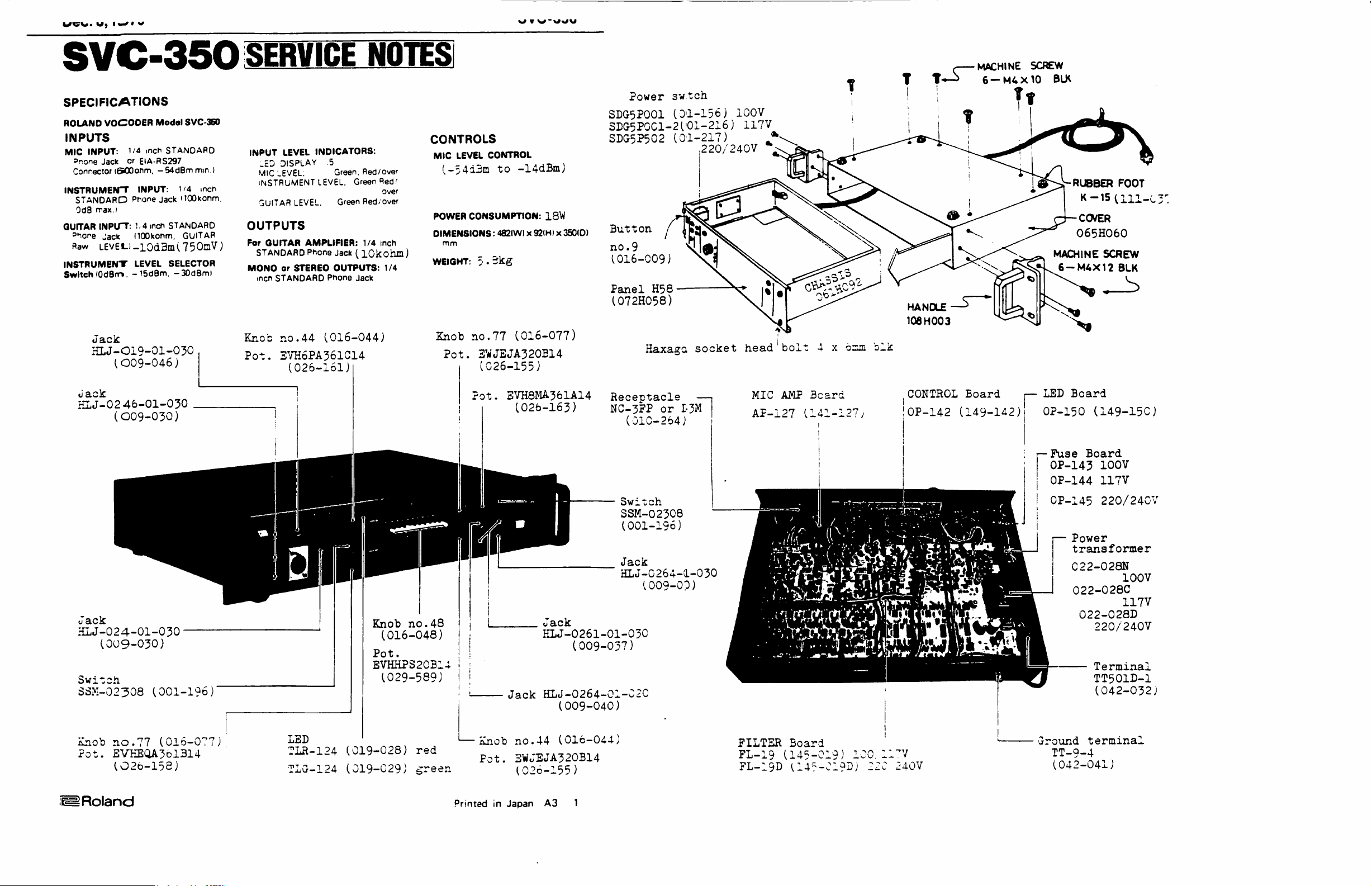
SPECIFICATIONS
ROLAND
VOCODER
Modal
SVC-360
INPUTS
MIC
INPUT:
snone
Connector
INSTRUMENT
STANDARD
OdB
QUrTAR
D*.one
flaw
INSTRUMENT
Switch
Jack
HLJ-OI9-01-030
1/4
inch
Jack
or
iciOOonm.
max.)
INPUT:
Jack
level.)-lOdBmi75OmV)
(OdBm.
STANDARD
EIA-RS297
-54dBm
INPUT:
Phone
1-4
dOOkonm.
LEVEL
-i5dBm,
1/4
Jack
HOOkonm,
inch
STANDARD
GUITAR
SELECTOR
-30dBm)
mm.)
men
INPUT
.ED
MIC
INSTRUMENT
GUITAR
OUTPUTS
For
STANDARD
MONO
inch
Knot
(O09-046)
Pot.
GUITAR
NOTES
LEVEL
DISPLAY
LEVEL.
or
STANDARD
no.44
3VH6PA361C14
INDICATORS:
5
Green.
LEVEL.
LEVEL.
AMPLIFIER:
Phone
STEREO
Phone
Red/over
Green
Green
Red/over
1/4
Jack ( lOkohia)
OUTPUTS:
Jack
(016-044)
(026-161)
Red'
over
inch
1/4
CONTROLS
MIC
LEVEL
CONTROL
(,-5413111
POWER
DIMENSIONS:
mm
WEIGHT: 5 •
Knob
Pot.
to
CONSUMPTION:
482(W) x 92(H) x 350(0)
3kg
no.77
3WJEJA320B14
(026-155)
SDG5P001
3DG5P0C1-2
SDG5P5O2
-14dBm)
13W
Button
no.
(016-009)
Panel
(072H058)
(016-077)
Power
3w.tch
9
H58
Haxa^a
(01-156)
('01-216)
100V
117V
(01-217)
220/240V
socket
head
bolt 4 x
czim
blk
t—->
HANDLE
108 H 00
3
c
MACHINE
6-M4X10
SCREW
BLK
MACHINE
6-M4X12
RUBBER
FOOT
K-15U11-C3'
CCVER
O65HO6O
SCREW
BLK
Jack
HLJ-O2
46-01-030
(O09-030)
Jack
HLJ-024-01-030
(009-030)
Switch
SSM-02308
(001-196
Pot.
Knob
no.48
(016-048)
Pot.
EVHHPS20B14
(029-589)
'
EVH8MA361A14
(026-163)
Recectacle
NC-3PP
Switch
SSM-02308
(001-196)
Jack
HLJ-C264-1-030
Jack
HLJ-O261-O1-O3C
(009-037)
Jack
HLJ-O264-O1-C2C
(009-040)
—(
or
I-3M
(010-264)
(009-OP)
MIC AMP
AP-127
(141-127/
Beard
CONTROL
OP-142
Board
(149-142)
i—
LED
OP-150
r-Fuse
OP-143
OP-144
OP-145
Board
(149-15C)
Board
100V
117V
220/24CV
Power
transformer
C22-028N
100V
022-028C
117V
022-028D
220/240V
Terminal
TT501D-1
(042-032)
Knob
rot.
no.77
(016-077)
EVEEQA361314
(O26-158)
LED
TLR-124
TLG-124
(019-028)
(019-029)
red
1—Knob
green
Printed
no.44
Pot.
3Wo"EJA320B14
(026-155)
in
Japan
(016-044)
A3
1
FILTER
FL-19
FL-19D
Board
(145-019)
(14--C1C)D)
100.
ll'V
22C
240V
Ground
terminal
TT-9-4
(042-041)
HOLD
Scan by Manual Manor
http://www.markglinsky.com/ManualManor.html
Dec.
8,1979
HOLD
MIC
K
2?
(»B0)
AIIIMO
AUDIO
DELAY
k—J
J
TC2K9
8BJ
AU&IO
DELAY
J
I
Q3C
031
LPF
LPF
Oil
LPF
038
IC53
ANALYZER
IC5O.55
EXPANDER
INSTR'
DIRECT
OT4
IC45
PEAK
PETCCBR
3IG.
BPF
-CONT
'red
FILTERS
OJ7
PEAK
METEC7&R
■LPF
5OHs
icHz
FL-19
r-
1
DC
TRIAN6UU*
IC44
OSC
fSi/3
SYNTHESIZER
A
SPF
:C2-7
Kit
/CA
M
33
IC38
VCA
IC37
8f«-3
Circuit
♦
DIRECT
i—■
f
ilL
"ON"
FILTERS
BPF
IC39
AMP
IC12a
re
i*
f
L.rt.M
ATT
l '
wt.
air
n
A
(A-»B)
CLOCK
OSC
Q32-O36
CLACK
AA
LPD-I
IC25
LFO'2
IC26.Q44
Q26
A
LNV-
ENSEMBLE
ON,
OFF
SVC-350
BLOCK
AMP
IC12b
DIAGRAM
I
L.W.H
LEVCL
AMP
-B.
1
'0
PHONES
MOUII
Scan by Manual Manor
http://www.markglinsky.com/ManualManor.html
IIUIM
-Deiail-
J
"/:.rTHE
JIZEli ? IL
:2h
TOCCDiiR
I1CLD
uec.
8,1979
After
Mic
proportional
The
by
Ipins
7-1
pins 6 and
As
causes
IC4
above
In
the
and
Ihe
3x?ander3
varies
thi3
reciy
flows,
Ten
IC55;
The
IC5l?in3
3pectrum.
peak
3tage
that
ampi—
3ignal
IC3
ijoea
aic
3i,sr.ai
(pir.3
1-3;,D*,
converted
7 in
the
mic
si-gnai
3A662
(pins
5-7;
10V
(2OVpp).
thi3
7oc
Mic
compressor
synthesizer
output
IC17-20,
in
the
fashion,
proportional
the
moire
3?Fs
witri a nign Q consisting
covers
3ignal
5-7)
Each.
is
letected,
filter
is
-Synthesiser
proportional
CCMPR3USCR
fled
by
14-54d3
to
id
to
she
control
coming
5-7),
Dl
and
jncothed
by
IC4
(.pins
parailed
increases,
conductance
to
retain
oder,
there
ir.
configuration:
filler
SXPAIJDSR
-voltage
same
3igr.al
signal
output
at
322
and
direction
flew
to
the
flows
ANALYZER
most
of
the
from
the
compressor
and
fed
to
3lice
goes
3moothed
to
*.he
through
i,pin3
5-7)
current
from
IC2
D2,
peak-voltage
to
DC
voltage
Mic
Head
whoje
gain
from
Q5
pin 7 La
by
1-3),Q5 • Connected
with feedback
Q5
output
to
increase,
either
are
pin 1 of
rate
control
half
two
other
channe-.
32;.
The
a3
in
through
through
resistors
current
lowering
peak
compressors
in
Guitar
IC5
io
current
the
Compressor,
IC13
current;
IC13.
FILTSR
of
ICs
audio
the
spectrum -3peech
is
pre-emphasized
filter
bank
which
to a iiode(e.g.
and
is
fed
to
the
filter.
This
jtrer-ght
of
i3 a control
that
Amp
or.
Ar-127,
i3
reversely
emitter.
full-wave
detected
IC5
rectified
by
(pir.3
1-3),
acros3
is
IC1
increases,that
the
gain
output
from
similar
preamp
al30
received
from
322
but
(IC2G/
the
(s.
is
more current
g.
IC<?G
signal.
through
slices
D37)
where
7CA
slice.
up
its
in
the
voltage
IC3
ani
IC4'3
3A6CJ.
of
$oing
to
ohain
oy
^323)
with
ii-
and
the
next
Trie
Jyr.th^ji»'.«r
ticai
■ii
IlAiuMCIIICS
3ound
ioea
•/oit'dge—
IC55.-C63),
IC33
to
exceeds
13
going
pin
rate
and
pul3e3ating
passing
from
"requer.cy
to
•-•oming
jpectrua
on
the
:ontroiied
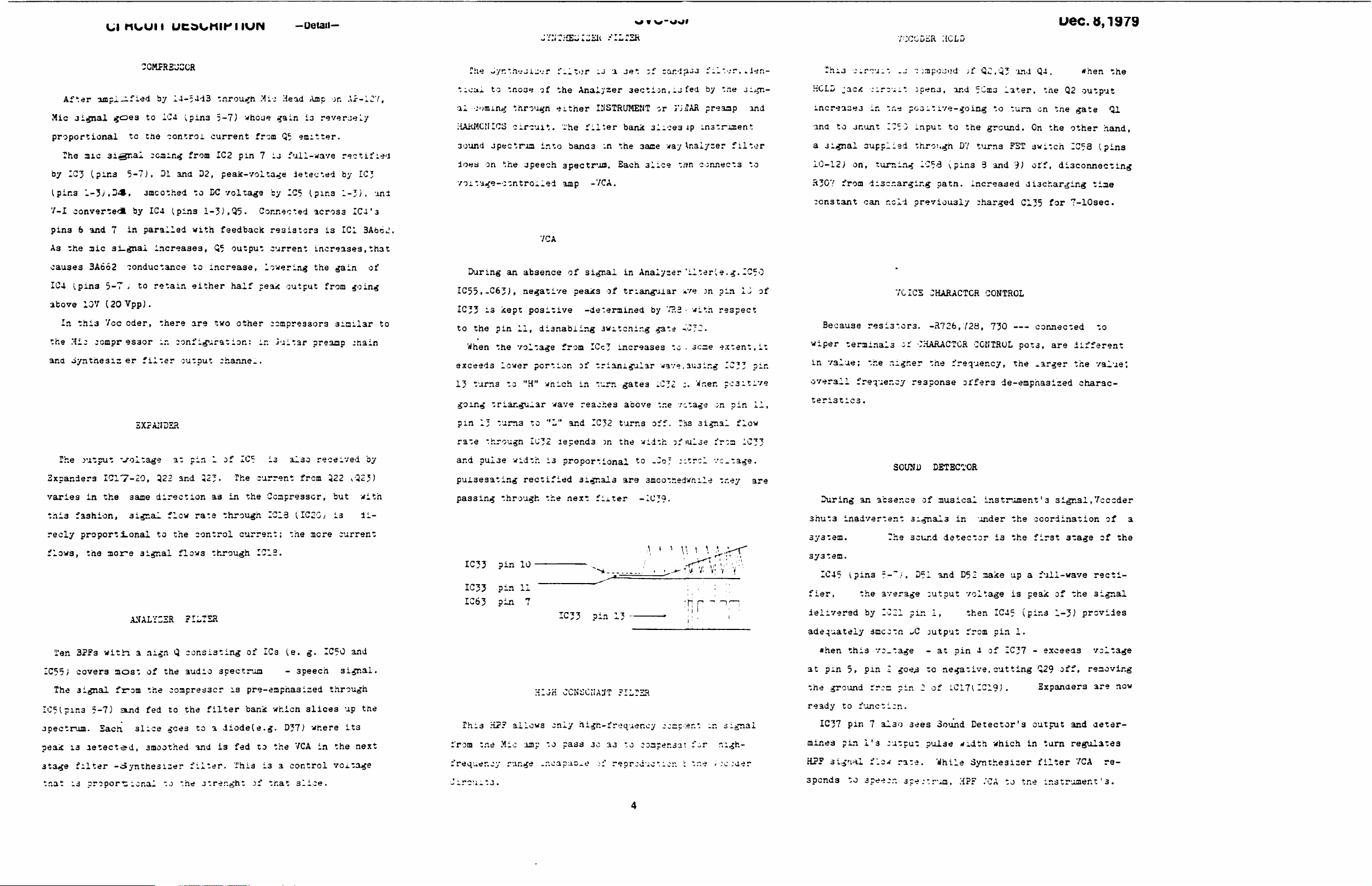
During
is
kept
the
pin
When
the
lower
turns
triangular
1;
tum3
througn
pulse
through
IC33
IC33
IC63
This
pin
pin
pin
H?F
tne
Mic
tnose
througn
circuit,
jpeech
an
absence
negative
positive
11,
voltage
to
"H"
to
IC32
width
rectified
10
11
7
allows
imp
range
f-itor u a
of
the
Analyzer
either
i'he
into
3pectrua.
amp
7CA
IllSTRUMENT
filter
banas
-7CA.
of
signal
peaks of
-determined
disnabling
from
ICc3
portion
wnich
the
HUH
.r.oapub^e
of
trianiguiar
in
turn
wave
reaches
"L"
and
IC32
aepend3
is
proportional
3ignal3
next
fixter
IC33
pin
CCNSCIIA3T
only
high-frequency
:o
pass
30
.:'
jet
^f
oar.'i?-^
3ection,iJfed
or
joJAR
bank
3lice3
:n
the
3aoe
Each
3lice
in
Analyser
trian^alar
by
3witcnir.g
increases
gates
above
turns
off.
sn
the
width
to
-Co;
are
smoothedwhile
-IC39.
1
Jp
way
Analyser
tr?n
'ilterie.g.IC5O
*ve
7?.3 • with
gata
-iC;2.
to . scae
wave,au3ing
1C32
:.
the
/ctage
Ths
of
lulse
;;trcl
-rj
FILTER
cccc'-.ent
aa
to
coaper.sa;
reprcciuc-.ior.
:
filr-jr,
by
preaap
instrument
connects
jn
.ier.-
tne
o.^n-
filter
pin
1J
and
to
respect
extent,
IC33
When
pc3itive
on
pin
signal
flow
:*r:a
1C33
ventage.
tr.ey
n
-n
signal
f^r
r.igh-
t.ie • :c
:aer
of
it
pin
11,
are
rhu
'jirrj;;
KCLD
jacit
circuit
mcrea3*3
and
to
a
3ignal
10-12)
H3O7
constant
Because
wiper
in
value;
overall
teristics
During
3hut3
system.
3y3tem.
IC45
fier,
ielivered
adequately
•hen
at
pin
the
ground
ready
IC37
mines
H?F
sigriHl
sponds
in
jnunt
supplied
on,
from
iiscr.argir.g
can
resi3*or3,
terminals
the
frequency
.
an
inadvertent
(?in3
the
by
smcctn
this
5,
pin I goe.s
rrea
to
function.
pin 7 al3o 3ees
pin
1's
flaw
to
s^e-izr.
.j
•:
i.-npoj.jd
:pen3,
-.r;-*
positive-going
175 0 input
to
through
turning
1C53
(pins 3 and
path,
r.old
previously
7CICS
JHARACTCR
-R726,728,
of
CHARACTCR
higher
the
response
SOUNU
absence
The
~-~},
average
IC21
vc.tage -at
DETECTOR
of
musical
3ignal3
sound
detector
D51
and D52
output
pir.
1,
^C
output
to
negative,
pin 2 of
Sound
output
pulse
rare.
3
peer
rum,
While
;f
QC.Q3
and
5Cm3
the
D7
turns
increased
charged
CONTROL
frequency,
offer3
in
under
voltage
then
from
pin 4 of IC37 -exceeas
1C17(IC19J.
Detector's
rfidth
Synthesizer
H?F
'lnd
Q.X.
later,
to
ground.
turn
On
FST
3witch
9)
off,
the
Q2
on tne
the
disconnecting
discharging
C135
for
CONTROL
730
connected
pots,
are
the
^arger
de-emphasized
instrument's
the
i3
the
make
up a full-wave
is
IC45
pin
1.
cutting
signal,7cccder
coordination
first
3tage
peak
of the
(pins
1-3)
Q29
off,
Expanders
output
which
in
turn
filter
.'CA
to
tne
instrument'
gate
other
IC53
7-10sec.
different
the
charac
and
regulates
7CA
*hen
the
output
Ql
hand,
(pins
time
to
value:
of
a
of the
recti
3ignal
provides
voltage
removing
are
now
deter
re
3.
CIRCUIT
Scan by Manual Manor
http://www.markglinsky.com/ManualManor.html
DESCRIPTION
—General-
Z.
Synthesiser
Like
the
first
,'3e;or.a;
filter,
liter
aausicai
and
"CAs
3cund
signal
i.
Kigir.
Filter
Frequency
\Reiionant
Voice
Signjil
Filter)
Bypass
Voice
from
XIC
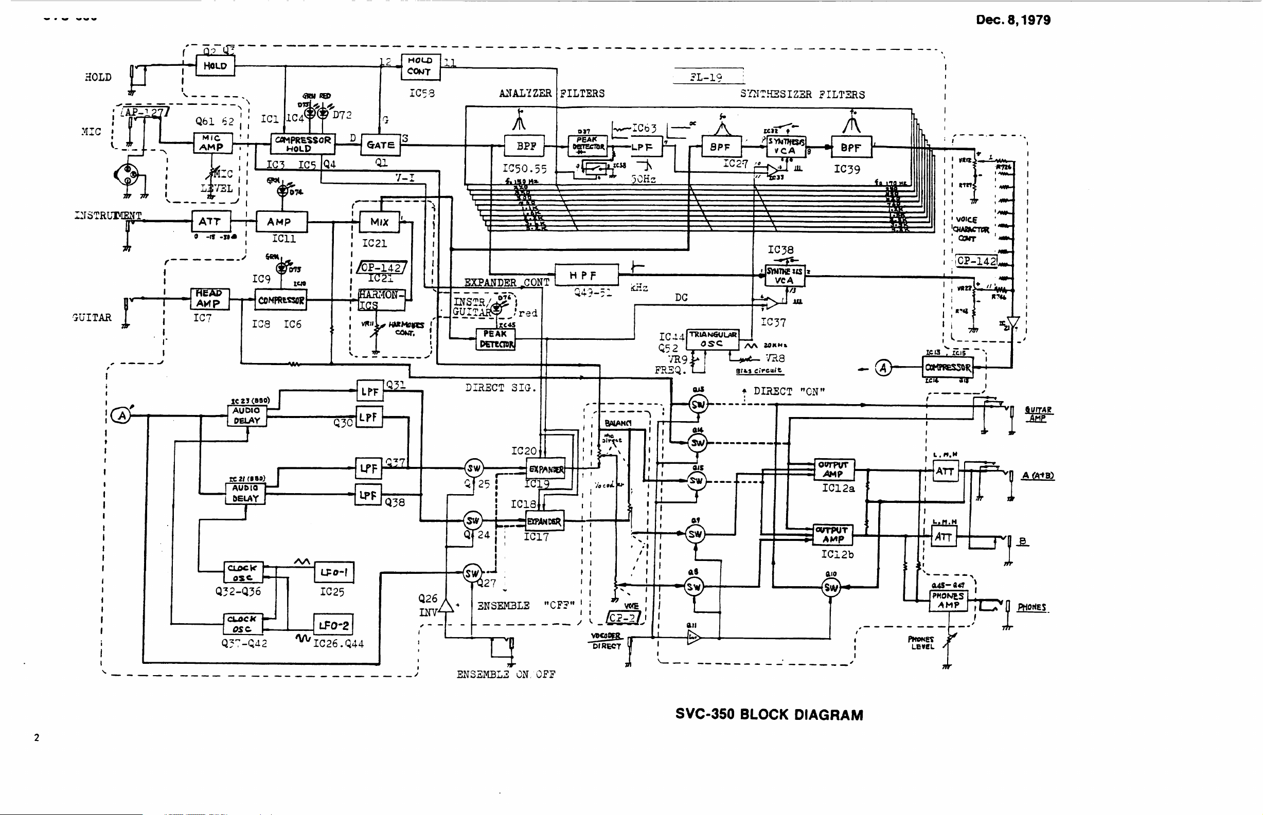
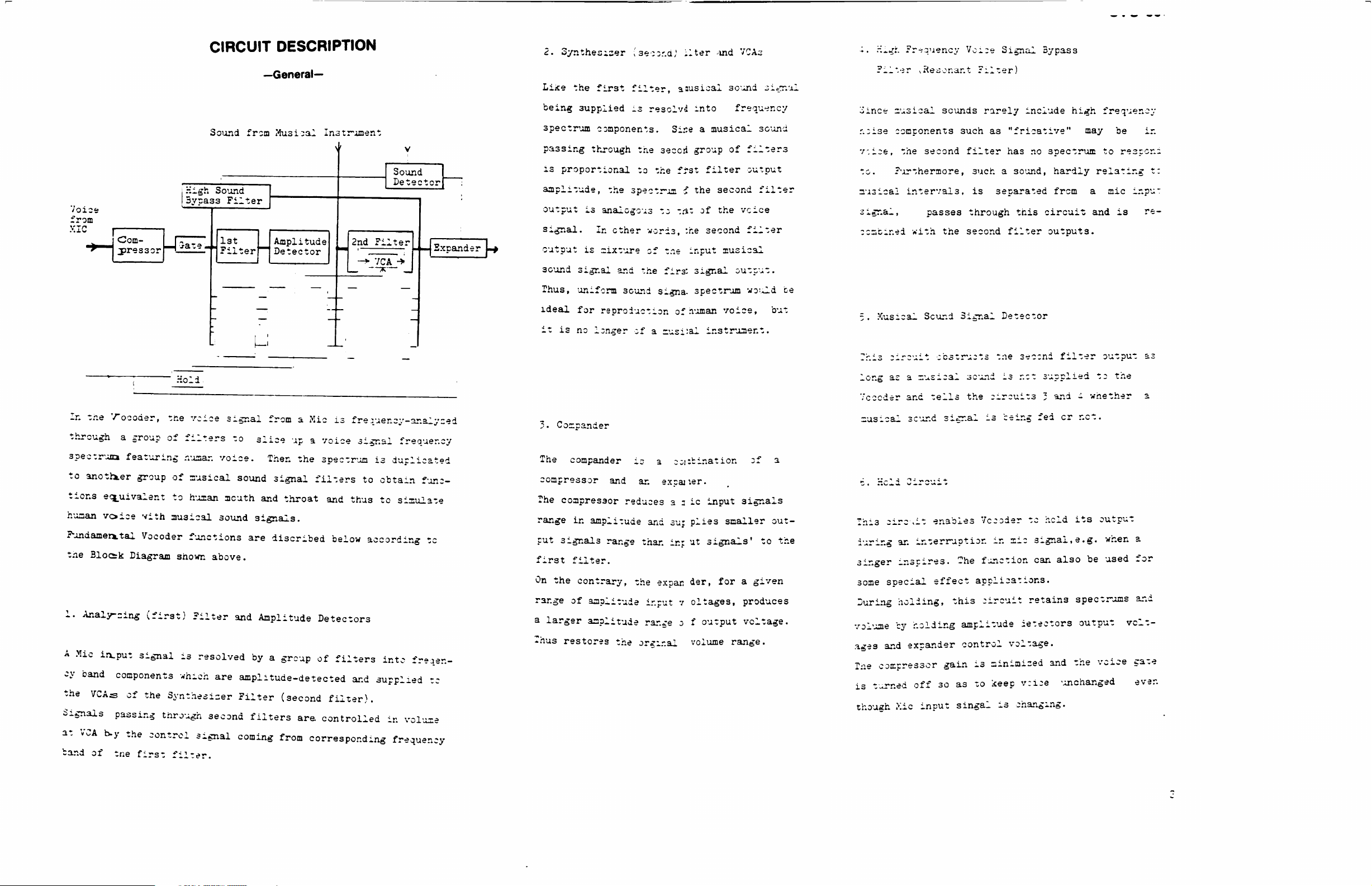
In
through a group
Com
pressor
the
Vocoder,
Holi
the
of
Sound
High
3yr:as3
voice
filters
from
Sound
Filter
1st
Filter
signal
to
Musical
Amplitude
Detector
from a Mic
slice
up a voice
Instrument
Sound
Detector
2nd
Filter
-*•
VCA
•*
is
frequency-analysed
signal
frequency
Sxcander
being
spectrum
passing
is
amplitude,
output
signal.
output
3cund
Thus,
ideal
it
3•
supplied
components.
through
proportional
the
is
analogous
In
ether
is
mixture
signal
uniform
for
reproduction
is
no
longer
Compander
is
resolvd
Sise a musical
the
3ecori
to
the
f*st
spectrum £ the
to
trit
words,
of
and
the
3ound
of a musi:al
:he
trie
input
firs:
signa.
of
human
into
group
of
signal
spectrum
frequency
of
filters
filter
second
output
second
the
vcice
filter
musical
output.
would
3ound
filter
voice,
instrument.
be
but
3mce
r.oise
V.ioe,
to.
musical
signal,
ccmbined
5.
This
long
Vocoder
musical
musical
components
the
Furthermore,
intervals,
with
Musical
circuit
as a musical
and
scur.d
sounds rarely
such
second
passes
Sound
tells
filter
such a sound,
is
through
the
second filter
Signal
-obstructs
sound
the
signal
is
include
as
"fricative"
has
no
separated
this
Detector
tne
second
is
not
circuits 3 and i whether
being
fed
high
frequency
may
spectrum
hardly
from a mic
circuit
outputs.
filter
supplied
cr
to
relating
and
output
to
net.
be
respen:
inpu"
is
the
in
t:
re-
a;
a
3pectruna
to
another
tions
human
Fundamental
t.ie
Blocsk
1.
Analyzing
A
Mic
cy
band
the
VCAs
Signals
at
VCA
band of
featuring
group
equivalent
voice
with
musical
Vocoder
Diagram
(first)
iixput
signal
components
of
the
Synthesiser Filter
passing
b.y
the
tne
through
control
first
filter.
huaar.
of
to
voice.
musical
human
sound
acuth
sound
functions
shown
above.
Filter
is
resolved
which
are
and
are
amplitude-detected
second
signal
coming
Then
the
spectrum
signal
and
filters
throat
and
signals.
discribed
Amplitude
by a group
(second
filters
are.
from
below
Detectors
of
filters
filter).
controlled
corresponding
is
duplicated
to
obtain
thus
to
according
into
and
supplied
in
func
simulate
to
freqen-
volume
frequency
tc
The
compander
compressor
The
compressor
range
cut
first
On
range
a
Thus
in
amplitude
signals
filter.
the
contrary,
of
amplitude
larger
amplitude
restores
is a combination
and
an
excajier.
reduces a a
and
range
than
the
input v oltages,
range o f
the
ordinal
expan
ic
su:
plies
inj
ut
der,
output
volume
input
signals'
3f
a
signals
smaller out-
to
the
for a given
produces
voltage.
range.
Thi3
circ
luring
singer
some
During
volume
ages
Tne
is
though
an
inspires,
special
holding,
by
and
expander
compressor
turned
,Xic
.it
enables
interruption
effect
holding
gain
off
so
input
Vocoder
in
-he
function
applications.
this
circuit
amplitude
control
is
as
to
singal
voltage.
minimised
1-ceep
is
to
hold
its
mic
signal,e.g.
can
also
retains
spec
ietectors
and
the
vcice
changing.
unchanged
output
when
be
used
trams
output
volt
vcice
a
for
and
gate
ever.
 Loading...