

Roland Corporation SPD-20 Owner's Manual

OWNER’S MANUAL
Thank you, and congratulations on your choice of the SPD-20
Total Percussion Pad. The SPD-20 is an electronic percussion unit
that has eight pads, trigger interfaces, a high-quality digital sound
generator, and on-board digital effects.
Since the SPD-20 includes a sound generator and effects in one
lightweight, compact package, you can use it anywhere, anytime.
A wide variety of options (pads, pedals, drum stand, etc.) are
available, allowing you to easily create a custom drum kit. By
adding sequencers or samplers, you can take advantage of the
possibilities of MIDI percussion.
The SPD-20 provides the flexibility and expandability that will be
appreciated by every percussionist, from beginner to professional.
About the Symbols in This Manual
Words or symbols enclosed in [square brackets] indicate panel
buttons or controls.
For example, [LAYER] signifies the Layer button.
Items marked by are supplementary explanations.
Items headed by explain important points concerning the
operation of your SPD-20.
Items preceded by give you useful tips and information
regarding the use of the SPD-20.
MEMO
NOTE
Before using this unit, carefully read the sections entitled: “USING THE UNIT SAFELY” and “IMPORTANT
NOTES” (Owner’s manual p. 2; p. 6). These sections pro-
vide important information concerning the proper operation of
the unit. Additionally, in order to feel assured that you have
gained a good grasp of every feature provided by your new
unit, Owner‘s manual should be read in its entirety. The manual should be saved and kept on hand as a convenient reference.
Copyright 1998 ROLAND CORPORATION
All rights reserved. No part of this publication may be reproduced in any
form without the written permission of ROLAND CORPORATION.
2
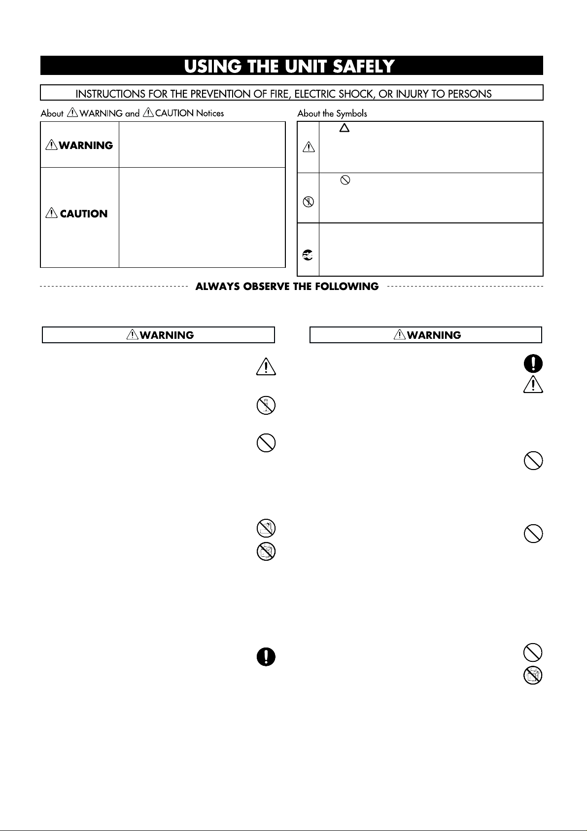
Used for instructions intended to alert
the user to the risk of injury or material
damage should the unit be used
improperly.
* Material damage refers to damage or
other adverse effects caused with
respect to the home and all its
furnishings, as well to domestic
animals or pets.
Used for instructions intended to alert
the user to the risk of death or severe
injury should the unit be used
improperly.
The ● symbol alerts the user to things that must be
carried out. The specific thing that must be done is
indicated by the design contained within the circle. In
the case of the symbol at left, it means that the powercord plug must be unplugged from the outlet.
The symbol alerts the user to important instructions
or warnings.The specific meaning of the symbol is
determined by the design contained within the
triangle. In the case of the symbol at left, it is used for
general cautions, warnings, or alerts to danger.
The symbol alerts the user to items that must never
be carried out (are forbidden). The specific thing that
must not be done is indicated by the design contained
within the circle. In the case of the symbol at left, it
means that the unit must never be disassembled.
• Before using this unit, make sure to read the
instructions below, and the Owner's Manual.
.........................................................................................................
• Do not open (or modify in any way) the unit or its
AC adaptor.
.........................................................................................................
• Do not attempt to repair the unit, or replace parts
within it (except when this manual provides specific instructions directing you to do so). Refer all
servicing to your retailer, the nearest Roland
Service Center, or an authorized Roland distributor, as listed on the "Information" page.
.........................................................................................................
• Never use or store the unit in places that are:
• Subject to temperature extremes (e.g., direct
sunlight in an enclosed vehicle, near a heating
duct, on top of heat-generating equipment); or
are
• Damp (e.g., baths, washrooms, on wet floors);
or are
• Humid; or are
• Dusty; or are
• Subject to high levels of vibration.
.........................................................................................................
• When using the unit with a rack or stand recommended by Roland, the rack or stand must be carefully placed so it is level and sure to remain stable.
If not using a rack or stand, you still need to make
sure that any location you choose for placing the
unit provides a level surface that will properly
support the unit, and keep it from wobbling.
.........................................................................................................
• Be sure to use only the AC adaptor supplied with
the unit. Also, make sure the line voltage at the
installation matches the input voltage specified on
the AC adaptor's body. Other AC adaptors may
use a different polarity, or be designed for a different voltage, so their use could result in damage,
malfunction, or electric shock.
.........................................................................................................
• Avoid damaging the power cord. Do not bend it
excessively, step on it, place heavy objects on it,
etc. A damaged cord can easily become a shock or
fire hazard. Never use a power cord after it has
been damaged.
.........................................................................................................
• This unit, either alone or in combination with an
amplifier and headphones or speakers, may be
capable of producing sound levels that could cause
permanent hearing loss. Do not operate for a long
period of time at a high volume level, or at a level
that is uncomfortable. If you experience any hearing loss or ringing in the ears, you should immediately stop using the unit, and consult an audiologist.
.........................................................................................................
• Do not allow any objects (e.g., flammable material,
coins, pins); or liquids of any kind (water, soft
drinks, etc.) to penetrate the unit.
.........................................................................................................
For the USA
FEDERAL COMMUNICATIONS COMMISSION
RADIO FREQUENCY INTERFERENCE STATEMENT
This equipment has been tested and found to comply with the limits for a Class B digital device, pursuant to Part 15 of the
FCC Rules. These limits are designed to provide reasonable protection against harmful interference in a residential
installation. This equipment generates, uses, and can radiate radio frequency energy and, if not installed and used in
accordance with the instructions, may cause harmful interference to radio communications. However, there is no guarantee
that interference will not occur in a particular installation. If this equipment does cause harmful interference to radio or
television reception, which can be determined by turning the equipment off and on, the user is encouraged to try to correct the
interference by one or more of the following measures:
– Reorient or relocate the receiving antenna.
– Increase the separation between the equipment and receiver.
– Connect the equipment into an outlet on a circuit different from that to which the receiver is connected.
– Consult the dealer or an experienced radio/TV technician for help.
Unauthorized changes or modification to this system can void the users authority to operate this equipment.
This equipment requires shielded interface cables in order to meet FCC class B Limit.
IMPORTANT: THE WIRES IN THIS MAINS LEAD ARE COLOURED IN ACCORDANCE WITH THE FOLLOWING CODE.
BLUE:
BROWN:
As the colours of the wires in the mains lead of this apparatus may not correspond with the coloured markings identifying
the terminals in your plug, proceed as follows:
The wire which is coloured BLUE must be connected to the terminal which is marked with the letter N or coloured BLACK.
The wire which is coloured BROWN must be connected to the terminal which is marked with the letter L or coloured RED.
Under no circumstances must either of the above wires be connected to the earth terminal of a three pin plug.
NEUTRAL
LIVE
For the U.K.
This product complies with the requirements of European Directive 89/336/EEC.
For EU Countries
For EU Countries
Apparatus containing
Lithium batteries
ADVARSEL!
Lithiumbatteri - Eksplosionsfare ved
fejlagtig håndtering.
Udskiftning må kun ske med batteri af
samme fabrikat og type.
Levér det brugte batteri tilbage til
leverandøren.
VARNING
Explosionsfara vid felaktigt batteribyte.
Använd samma batterityp eller en
ekvivalent typ som rekommenderas av
apparattillverkaren.
Kassera använt batteri enligt
fabrikantens instruktion.
CAUTION
Danger of explosion if battery is
incorrectly replaced.
Replace only with the same or
equivalent type recommended by the
manufacturer.
Discard used batteries according to the
manufacturer’s instructions.
ADVARSEL
Eksplosjonsfare ved feilaktig skifte av
batteri.
Benytt samme batteritype eller en
tilsvarende type anbefalt av
apparatfabrikanten.
Brukte batterier kasseres i henhold til
fabrikantens instruks joner.
VAROITUS
Paristo voi räjähtää, jos se on
virheellisesti asennettu.
Vaihda paristo ainoastaan
laitevalmistajan suosittelemaan
tyyppiin. Hävitä käytetty paristo
valmistajan ohjeiden mukaisesti.
For Canada
This Class B digital apparatus meets all requirements of the Canadian Interference-Causing Equipment Regulations.
Cet appareil numérique de la classe B respecte toutes les exigences du Règlement sur le matériel brouilleur du Canada.
NOTICE
AVIS
• Immediately turn the power off, remove the AC
adaptor from the outlet, and request servicing by
your retailer, the nearest Roland Service Center, or
an authorized Roland distributor, as listed on the
"Information" page when:
• The AC adaptor or the power-supply cord has
been damaged; or
• Objects have fallen into, or liquid has been
spilled onto the unit; or
• The unit has been exposed to rain (or otherwise
has become wet); or
• The unit does not appear to operate normally
or exhibits a marked change in performance.
.........................................................................................................
• In households with small children, an adult should
provide supervision until the child is capable of
following all the rules essential for the safe operation of the unit.
.........................................................................................................
• Protect the unit from strong impact.
(Do not drop it!)
.........................................................................................................
• Do not force the unit's power-supply cord to share
an outlet with an unreasonable number of other
devices. Be especially careful when using extension cords—the total power used by all devices
you have connected to the extension cord's outlet
must never exceed the power rating
(watts/amperes) for the extension cord. Excessive
loads can cause the insulation on the cord to heat
up and eventually melt through.
.........................................................................................................
• Before using the unit in a foreign country, consult
with your retailer, the nearest Roland Service
Center, or an authorized Roland distributor, as listed on the "Information" page.
.........................................................................................................
• The unit and the AC adaptor should be located so
their location or position does not interfere with
their proper ventilation.
.........................................................................................................
• Always grasp only the plug or the body of the AC
adaptor when plugging into, or unplugging from,
an outlet or this unit.
.........................................................................................................
• Whenever the unit is to remain unused for an
extended period of time, disconnect the AC adaptor.
.........................................................................................................
• Try to prevent cords and cables from becoming
entangled. Also, all cords and cables should be
placed so they are out of the reach of children.
.........................................................................................................
• Never climb on top of, nor place heavy objects on
the unit.
.........................................................................................................
• Never handle the AC adaptor body, or its plugs,
with wet hands when plugging into, or unplugging from, an outlet or this unit.
.........................................................................................................
• Before moving the unit, disconnect the AC adaptor
and all cords coming from external devices.
.........................................................................................................
• Before cleaning the unit, turn off the power and
unplug the AC adaptor from the outlet (p. 12).
.........................................................................................................
• Whenever you suspect the possibility of lightning
in your area, disconnect the AC adaptor from the
outlet.
.........................................................................................................
3
1
2
3
4
5

USING THE UNIT SAFELY.............................................2
How to Use This Manual..................................................5
Important Notes ................................................................6
Main Features of the SPD-20............................................7
Panel Descriptions.............................................................8
Attaching the SPD-20 to a Drum Stand........................10
Using the Slit Tape (Included).......................................10
How to Restore the Factory Settings
(System Initialize)........................................................11
CHAPTER 1 Quick Start
Connection to Audio Equipment..................................12
Playing the Pads ..............................................................12
Turning the Power On ........................................................12
Turning the Power Off........................................................13
Adjusting the Volume.........................................................13
Selecting a Patch..............................................................14
What is a Patch?...................................................................14
Using a Footswitch to Select Patches................................15
Comparing Layered Sounds..........................................15
What is a Pad Bank?............................................................16
What is the Layer Function?...............................................17
CHAPTER 2 Using the SPD-20 by Itself
About the SPD-20’s Internal Setup and Parameter
Settings (Edit)...............................................................18
What Kind of Instrument is the SPD-20? .........................18
Internal Organization..........................................................18
Play Mode and Edit Mode..................................................19
How to Edit...........................................................................20
Selecting and Adjusting Sounds
(Sound Parameters).....................................................22
Selecting a Sound (INST)....................................................22
Adjusting the Volume (LEVEL).........................................23
Adjusting the Pitch (PITCH)..............................................23
Adjusting the Decay (DECAY) ..........................................23
Adjusting the Stereo Position (PAN)................................23
Adjusting the Dynamic Volume Response (CURVE).....24
Adjusting the Effects Depth (FX SEND)...........................25
How to Edit Sound Parameters.........................................26
Adding Reverberation and Other Effects to the Sound
(Effect Parameters)......................................................28
Select an Effect (FX TYPE)..................................................28
Setting Effect Duration and Rate (FX TIME) ...................28
Adjust the Effect Depth for the Entire Patch
(FX LEVEL).......................................................................28
How to Edit Effect Parameters...........................................29
Adjusting the Pad Sensitivity (TRIG SENS)................30
Setting the Pad’s Minimum Level
(TRIG THRESHOLD)......................................................31
Copying a Patch (COPY)................................................32
Setting Up Your Own Patch Sequences
(Patch Chain)................................................................33
What is a Patch Chain?........................................................33
Setting up a Patch Chain.....................................................33
Using a Patch Chain to Select Patches..............................34
Erasing a Patch Chain .........................................................34
CHAPTER 3 Connecting External Pads or Pedals
Connecting External Pads or Hi-Hat Control Pedal ..35
Connecting External Pads or the Special Pedal...............35
Precautions When Connecting a External Pad................37
Precautions When Connecting
the PD-100 or PD-120......................................................38
How to Use the Rim Shot and Cymbal Choke
Playing Techniques.........................................................39
Precautions When Connecting
a Hi-Hat Control Pedal...................................................40
Using a Footswitch as a Hold Pedal..................................41
Settings for External Pads or Kick Trigger Units........42
Setting External Pad Tone and MIDI Parameters...........42
How to Edit the Trigger Parameters.................................42
Setting Parameters for Reliable Performance using
Acoustic Drum Triggers and Other Manufacturers’
Pads (Advanced Trigger Parameters)...........................48
Settings for an External Hi-Hat Control Pedal............54
Controlling the Tone with the Hi-Hat
Control Pedal—Pedal Control (PDL CTRL)................54
Adjusting the Volume of the Pedal Hi-Hat Sound
(PDL LEVEL)....................................................................55
Using the Hi-Hat Control Pedal’s Action to Set
Controller Numbers for Sending and Receiving
MIDI Data (PDL CC#).....................................................56
CHAPTER 4 Connecting MIDI Devices
MIDI Connections ...........................................................57
About MIDI......................................................................57
How MIDI Data is Sent and Received..............................57
Main Types of MIDI Data Used by the SPD-20...............58
MIDI Parameter Settings................................................61
How the MIDI Parameters Work ......................................61
Setting MIDI Parameters ....................................................66
Priority Ranking of Note Number Expression................67
Using the SPD-20 as a MIDI Sound Module ...............67
Setting the Receive Channel (Basic Channel) ..................67
Table of Contents
4

Settings for Each Pad...........................................................68
Using External MIDI Devices to Play the Internal
Sound Generator..............................................................69
Expanding Patches to Allow Reception of Many
Note Numbers (Patch Expand) .....................................69
How to Use a Sequencer or a Computer to
Record/Play back Your Performance ......................72
Connecting a Computer (or a Sequencer)........................72
Breaking/Cutting the Connection Between the Sound
Generator and the Pad Controller (Local Control).....72
How to Set Up the SPD-20 for Sequencing......................74
Storing the SPD-20’s Data in External Devices
(Bulk Dump) ....................................................................75
How to Transmit (Bulk Dump)..........................................75
How to Receive (Bulk Load) ..............................................76
Reading SPD-11 Data with the SPD-20.............................77
What is Device ID ................................................................78
CHAPTER 5 Supplementary Materials
Taking Advantage of the On-board Effects.................79
Troubleshooting...............................................................82
Error Messages.................................................................87
Instrument List.................................................................88
Patch List ..........................................................................93
Parameter List..................................................................94
Trigger Type Internal Parameters
(Advanced Trigger Parameters) ........................................94
Blank Parameter Chart ...................................................95
Roland Exclusive Message.............................................96
MIDI Implementation.....................................................98
MIDI Implementation Chart........................................102
How to Read a MIDI Implementation Chart ............103
Specifications..................................................................104
Index................................................................................105
How-To Index................................................................106
How to Use This Manual
This manual provides a step-by-step introduction to the many
functions of the SPD-20. If this is your first time using electronic drums, or a MIDI device, please read the manual from
beginning to end. If you are already familiar with electronic
percussion and sequencers, you may not need to read the
entire manual. Glance briefly over Chapters 1 & 2, then refer
to other sections as necessary, while you experiment with the
SPD-20. You will soon learn how the unit works. If you don’t
understand the meaning of a term or how a function works,
use the index to find the appropriate explanation.
CHAPTER 1 Quick Start
Read this chapter first to learn how to play using the SPD-20.
It guides you quickly through the basics, up to the point
where you can produce sound. All the fundamental operating procedures are also introduced.
CHAPTER 2 Using the SPD-20 by Itself
Read this chapter if you wish to use the SPD-20 as a standalone unit. Here you will find a variety of information, such
as how the unit is organized internally, as well as how to
modify the sounds.
CHAPTER 3
Connecting External Pads or Pedals
Read this chapter when you wish to connect external pads or
hi-hat control pedal to the SPD-20.
CHAPTER 4 Connecting MIDI Devices
Read this chapter when you wish to use the SPD-20 to play
an external sound module, to have sequencer performance
data played through the SPD-20, or to save data from the
SPD-20 to a sequencer.
CHAPTER 5 Supplementary Materials
Supplementary sections provided with this manual include
“Troubleshooting,” a “Instrument List,” and the “MIDI
Implementation” chart. Read this when, for example, you
need a solution to some difficulty in operating the unit, or
when you just want to know about MIDI in greater detail.
You can find both a subject-specific index and general index
at the end of this manual.
If you will be using the SPD-20 by itself, there is no
need for you to read Chapters 3 and 4, or the MIDI
Implementation section in Chapter 5 (p. 98–101).
The explanations in this manual include illustrations that depict what should typically be
shown by the display. Note, however, that your
unit may incorporate a newer, enhanced version
of the system (e.g., includes newer sounds), so
what you actually see in the display may not
always match what appears in the manual.
MEMO
NOTE
5
1
2
3
4
5

In addition to the items listed under “USING THE UNIT SAFELY” on page 2, please read and observe the following:
Important Notes
6
Power Supply
• Do not use this unit on the same power circuit with any
device that will generate line noise (such as an electric
motor or variable lighting system).
• The AC adaptor will begin to generate heat after long
hours of consecutive use. This is normal, and is not a
cause for concern.
• Before connecting this unit to other devices, turn off the
power to all units. This will help prevent malfunctions
and/or damage to speakers or other devices.
Placement
• Using the unit near power amplifiers (or other equipment containing large power transformers) may induce
hum. To alleviate the problem, change the orientation of
this unit; or move it farther away from the source of
interference.
• This device may interfere with radio and television
reception. Do not use this device in the vicinity of such
receivers.
• Do not expose the unit to direct sunlight, place it near
devices that radiate heat, leave it inside an enclosed vehicle, or otherwise subject it to temperature extremes.
Excessive heat can deform or discolor the unit.
Maintenance
• For everyday cleaning wipe the unit with a soft, dry
cloth or one that has been slightly dampened with water.
To remove stubborn dirt, use a cloth impregnated with a
mild, non-abrasive detergent. Afterwards, be sure to
wipe the unit thoroughly with a soft, dry cloth.
• Never use benzine, thinners, alcohol or solvents of any
kind, to avoid the possibility of discoloration and/or
deformation.
Repairs and Data
• Please be aware that all data contained in the unit’s
memory may be lost when the unit is sent for repairs.
Important data should always be backed up in another
MIDI device (e.g., a sequencer), or written down on
paper (when possible). During repairs, due care is taken
to avoid the loss of data. However, in certain cases (such
as when circuitry related to memory itself is out of
order), we regret that it may not be possible to restore the
data, and Roland assumes no liability concerning such
loss of data.
Memory Backup
• This unit contains a battery which powers the unit’s
memory circuits while the main power is off. When this
battery becomes weak, the message shown below will
appear in the display. Once you see this message, have
the battery replaced with a fresh one as soon as possible
to avoid the loss of all data in memory. To have the battery replaced, consult with your retailer, the nearest
Roland Service Center, or an authorized Roland distributor, as listed on the “Information” page.
Additional Precautions
• Unfortunately, it may be impossible to restore the contents of data that was stored in another MIDI device (e.g.,
a sequencer) once it has been lost. Roland Corporation
assumes no liability concerning such loss of data.
• Use a reasonable amount of care when using the unit’s
buttons, sliders, or other controls; and when using its
jacks and connectors. Rough handling can lead to malfunctions.
• Never strike or apply strong pressure to the display.
• When connecting/disconnecting all cables, grasp the
connector itself—never pull on the cable. This way you
will avoid causing shorts, or damage to the cable’s internal elements.
• To avoid disturbing your neighbors, try to keep the
unit’s volume at reasonable levels. You may prefer to use
headphones, so you do not need to be concerned about
those around you (especially when it is late at night).
• This instrument is designed to minimize the extraneous
sounds produced when it's played. However, since
sound vibrations can be transmitted through floors and
walls to a greater degree than expected, take care not to
allow these sounds to become a nuisance to neighbors,
especially when performing at night and when using
headphones.
• When you need to transport the unit, package it in the
box (including padding) that it came in, if possible.
Otherwise, you will need to use equivalent packaging
materials.

• The SPD-20 features 700 different internal instruments, including drum set sounds, percussion sounds from around the world, dance sounds, sound effects, phrase loops, and more,
that can be used in a wide variety of musical genres. (Instrument List p. 88)
• Each sound can be edited using a wide variety of sound parameters, including level, pitch,
decay, pan, velocity curve, and effect send (p. 22).
• Using the Layer function, different Velocity Curves can be assigned to each of two sounds,
and the two sounds mixed (or switched) by your playing dynamics (p. 17).
• The on-board digital effects unit (Reverb, Delay, Chorus and Flanger) allows you to set the
effect depth independently for each sound assigned to a pad (p. 28).
• Four external dual trigger inputs are provided, allowing you to connect kick trigger units
(KD-7s; sold separately) or pads (PD-7, PD-9, PD-5, PD-120, PD-100: sold separately), for
playing in conjunction with the SPD-20’s pads (p. 35). When you connect the PD-7 or PD-9,
you can enjoy such drum techniques as snare rim shots and cymbal choking (p. 39). With the
PD-120 connected, you can play rim shots. What’s more, you can play the SPD-20’s sounds
using an acoustic drum trigger attached to an acoustic drum (p. 45).
• When a hi-hat control pedal (FD-7; sold separately) is connected, you have continuous control (from closed to open) of the hi-hat sounds (p. 54).
• Settings for the SPD-20’s 8 pads, 4 external pads, hi-hat control pedal, and the effects unit can
be stored as one of 99 Patches. This means that a single SPD-20 is able to store and instantly
recall 99 different percussion “sets,” covering virtually any style of music you can imagine.
• Using the Patch Chain function, you can create and store a sequence of up to 16 Patches
which can be selected in a predetermined order (convenient for use within a song). The SPD20 can store eight such Patch Chains (p. 33).
• For each pad, you can set two independent MIDI transmit channels and Velocity Curves, so
that your playing dynamics can control external and internal sound generators (p. 61).
• The SPD-20 is fully expandable via MIDI, and is especially powerful when used with a
sequencer. For example, you might record SPD-20 settings as bulk data (p. 75) at the beginning of sequencer song data, or allow the sequencer to take care of Patch selection so that you
can concentrate on playing.
Main Features of the SPD-20
7
1
2
3
4
5
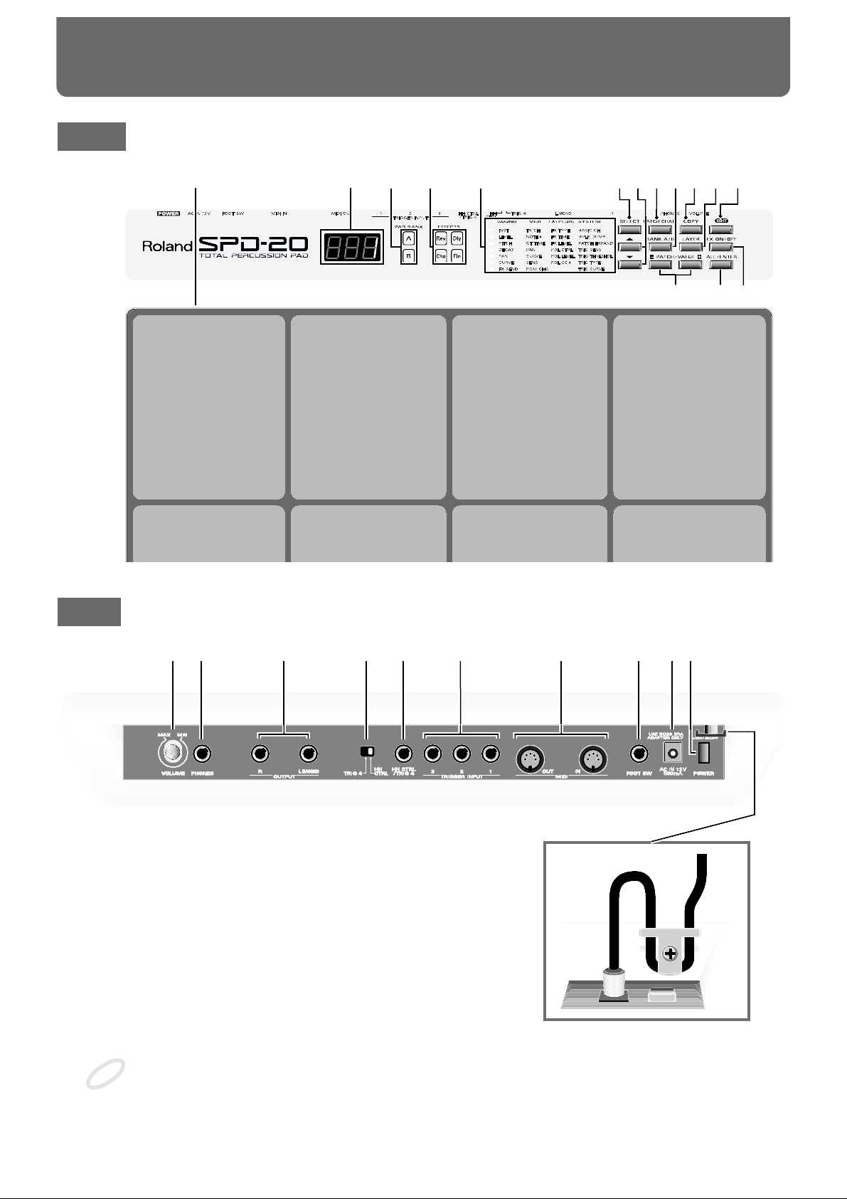
Front
fig. (Front Panel)
Rear
fig. (Rear Panel and Cord Hook)
Cord Hook
To prevent the disruption of power to your unit (should the plug be pulled out accidentally), and to
avoid applying undue stress to the AC adaptor jack, anchor the power cord using the cord hook, as
shown in the illustration.
21354
14 1315
6 7 8 9 10 1112
Pad 1 Pad 2 Pad 3 Pad 4
Pad 5 Pad 6 Pad 7 Pad 8
16 17 18 19 20 21 22 23 24 25
NOTE
Panel Descriptions
8

1 Pads 1–8
Play these pads to trigger the various sounds. The
pads are velocity sensitive and will respond to your
playing dynamics.
2 Patch display
This display indicates the Patch number or the value
of each parameter (p. 14).
3 PAD BANK indicator
Indicates the selected pad bank (A or B) (p. 16).
4 EFFECT indicator
The LED of the selected effect will light (p. 28).
5 Parameter List
In the Edit mode, the indicator of the selected parameter will light (p. 20). Use the [SELECT] (Parameter
Group Select) and [ ][ ] (Parameter Select) buttons to choose parameters (p. 21).
6
Parameter Group Select button [SELECT]
In the Edit mode, this button selects the desired parameter group: SOUND, MIDI, FX/PEDAL, or SYSTEM (p. 21).
7 Parameter Select buttons [ ][ ]
In the Edit mode, use these buttons to select a parameter within the parameter group (p. 21).
8 [PATCH CHAIN] button
Use this button when setting up or playing a Patch
Chain (p. 33).
9 [BANK A/B] button
Switches you between pad banks A and B
(p. 16).
10 [COPY] button
Use to copy data from one Patch to another (p. 32).
11 [LAYER] button
This button allows the sounds assigned to pad banks
A and B to be played together (p. 15).
12 [EDIT] button
This button switches between the Edit and Play
modes (p. 19).
13 [FX ON/OFF] button
This button turns the effects on or off (p. 28).
14 [ALL/ENTER] button
Use this button when setting all pads to the same
value (p. 27), when performing a copy (p. 32), or
when storing Patch Chain settings (p. 33).
15 PATCH/VALUE [-], [+] buttons
These buttons are used to select Patches. In the Edit
mode they are used to modify parameter values
(p. 14).
16 VOLUME knob
Adjusts the volume of the OUTPUT jacks and
PHONES jack (p. 13).
17 PHONES jack
A pair of stereo headphones can be connected to this
jack. Even with headphones connected, the OUTPUT
jacks will still be active (p. 12).
18 OUTPUT (R, L/MONO) jacks
These jacks output the sound of the SPD-20. For
monaural output use the L/MONO jack (p. 12).
19 [HH CTRL/TRIG 4] select switch
If a hi-hat control pedal (FD-7; sold separately) is connected to the hi-hat control pedal jack, set this switch
to HH CTRL (p. 40). If an external pad is connected,
set this switch to TRIG 4 (p. 37).
20 HH CTRL/TRIG 4 jack
A hi-hat control pedal (FD-7; sold separately) can be
connected to this jack. If the external input select
switch is set to TRIG 4, an external pad can be connected to this jack (p. 35, 36).
21. TRIGGER INPUT 1–3 jacks
External pads etc. can be connected here (p. 37).
Use Trigger Input jack 1 and 2 to allow the playing of rim shots when using a PD-120 pad (p. 38).
22. MIDI IN/OUT connectors
External MIDI devices can be connected here (p. 57).
23. FOOT SW jack
A footswitch can be connected here allowing you to
change Patches by remote control. If you use a special
cable (PCS-31; sold separately) to connect two FS-5U
switches (sold separately), you can move up or down
through the Patch numbers. If you connect a DP-2
switch (sold separately), you can move up (but not
down) through the Patch numbers (p. 15).
24. AC adaptor jack
Connect the included AC adaptor here (p. 12).
Use only the included AC
adaptor. Use of any other AC
adaptor may cause damage or
malfunction.
25. POWER switch
This switch turns the unit on/off (p. 12).
MEMO
9
1
2
3
4
5
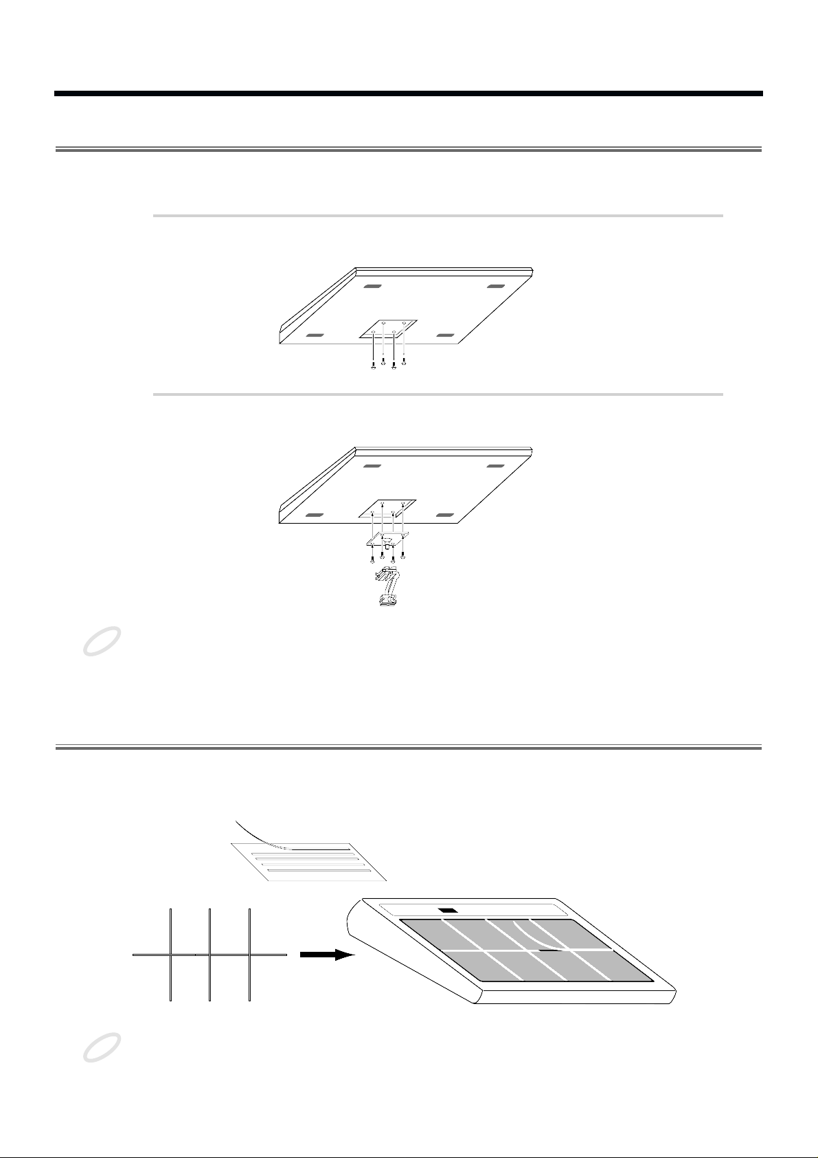
Attaching the SPD-20 to a Drum Stand
If you are attaching the unit to a cymbal stand etc. with a pipe diameter of 10.5–30 mm, use an all purpose clamp set (APC-33: sold separately).
1
Using a 4 mm wrench, remove the four screws from the bottom of
the SPD-20.
fig.3
2
Use the four screws you removed in step 1 to attach the stand holder to the bottom of the SPD-20.
fig.4
The screws included with the APC-33 cannot be used.
Using the Slit Tape (Included)
Place the Slit tape, included with the SPD-20, along the slits, or grooves around each of the pads. The
Slit tape allows you to clearly distinguish where each pad is, even on stage or in other darkened locations.
fig. Slit Tape
Please note that Roland does not handle replacements or additional purchases of Slit Tape.
NOTE
54
321
NOTE
10

How to Restore the Factory Settings (System Initialize)
When the SPD-20 is shipped, it contains 99 Patches in memory. You can freely overwrite this data.
However, the same data is also preserved in ROM, and can be restored at any time. This procedure is
called System Initialize.
The explanations in this manual assume that the SPD-20 is still in its factory initialized state. We recommend that before you begin using the unit, you perform this System Initialize operation.
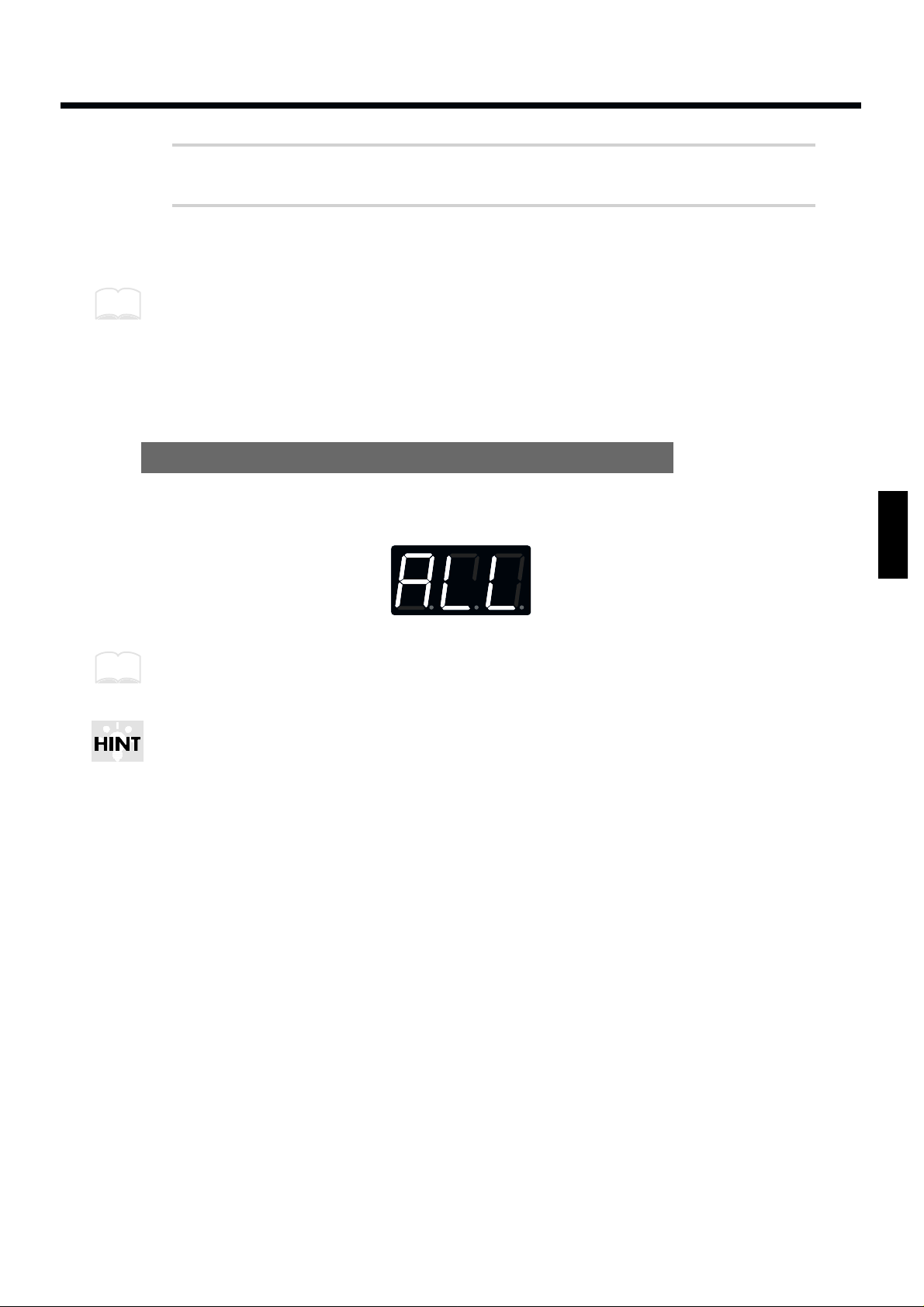
When you execute the System Initialize operation, all your edited data will be lost. If your SPD-20
contains important edited data, you should make a note of the settings or store the data in an external
device such as a sequencer (p. 75).
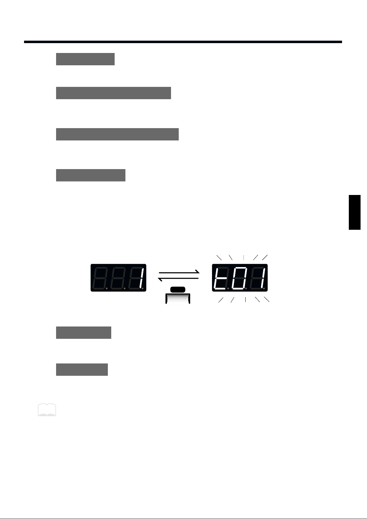
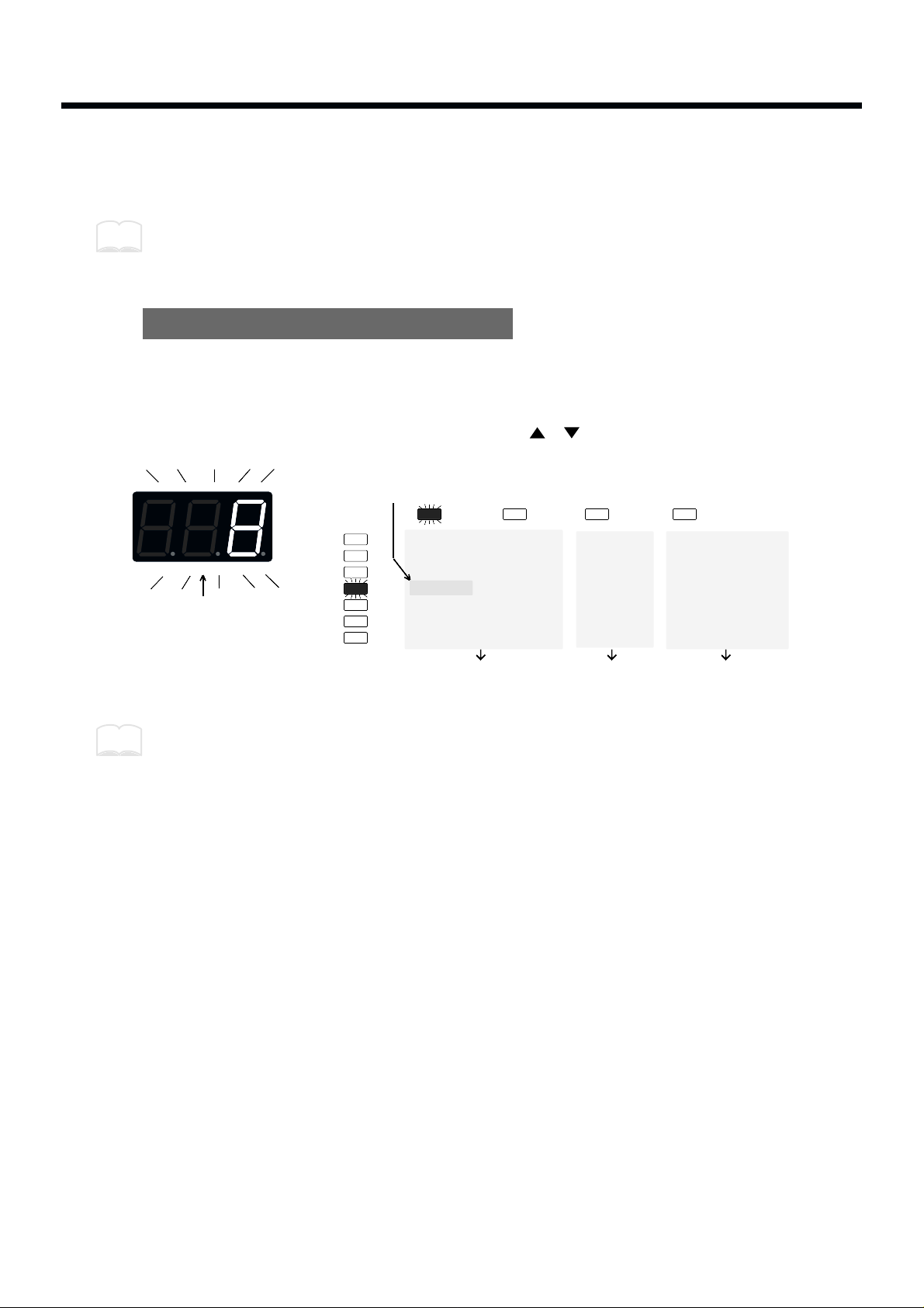
1
While holding down [ ] and [ALL/ENTER], turn the power on.
The following display will appear.
fig.5
2
Press [ALL/ENTER] and the data will be initialized.
If you wish to quit without initializing, press any key other than [ALL/ENTER].
It is possible to restore the factory settings of a single patch with Patch Copy (p. 32).
ROM
This is an abbreviation for Read Only Memory, which is a type of memory that can only be read;
modification or deletion is not possible.
NOTE
MEMO
11
1
2
3
4
5
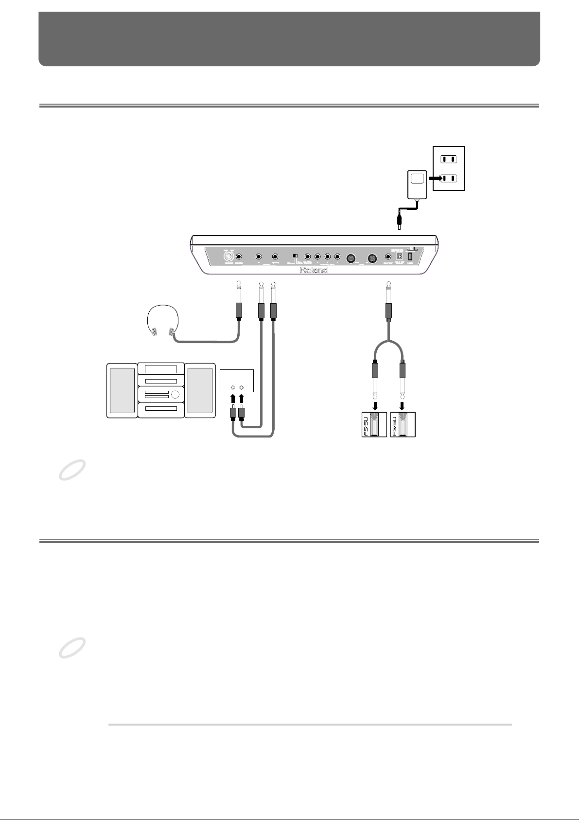
Connection to Audio Equipment
With the SPD-20, you can produce realistic sounds simply by connecting an audio system. You can also
use headphones.
fig.6
To prevent malfunction and/or damage to speakers or other devices, always turn down the volume,
and turn off the power on all devices before making any connections.
Playing the Pads
When connections are complete, you can play the SPD-20.
Turning the Power On
The POWER switch is on the rear panel.
Once the connections have been completed, turn on power to your various devices in the order specified. By turning on devices in the wrong order, you risk causing malfunction and/or damage to speakers and other devices.
Always make sure to have the volume level turned down before switching on power. Even with the
volume all the way down, you may still hear some sound when the power is switched on, but this is
normal, and does not indicate a malfunction.
1
Check that all connections with other devices are correct, and that
everything is off.
LINE IN
LR
AC adaptor
Audio Equipment
(Stereo set)
Footswitches
Stereo Headphones
NOTE
NOTE
CHAPTER 1 Quick Start
12
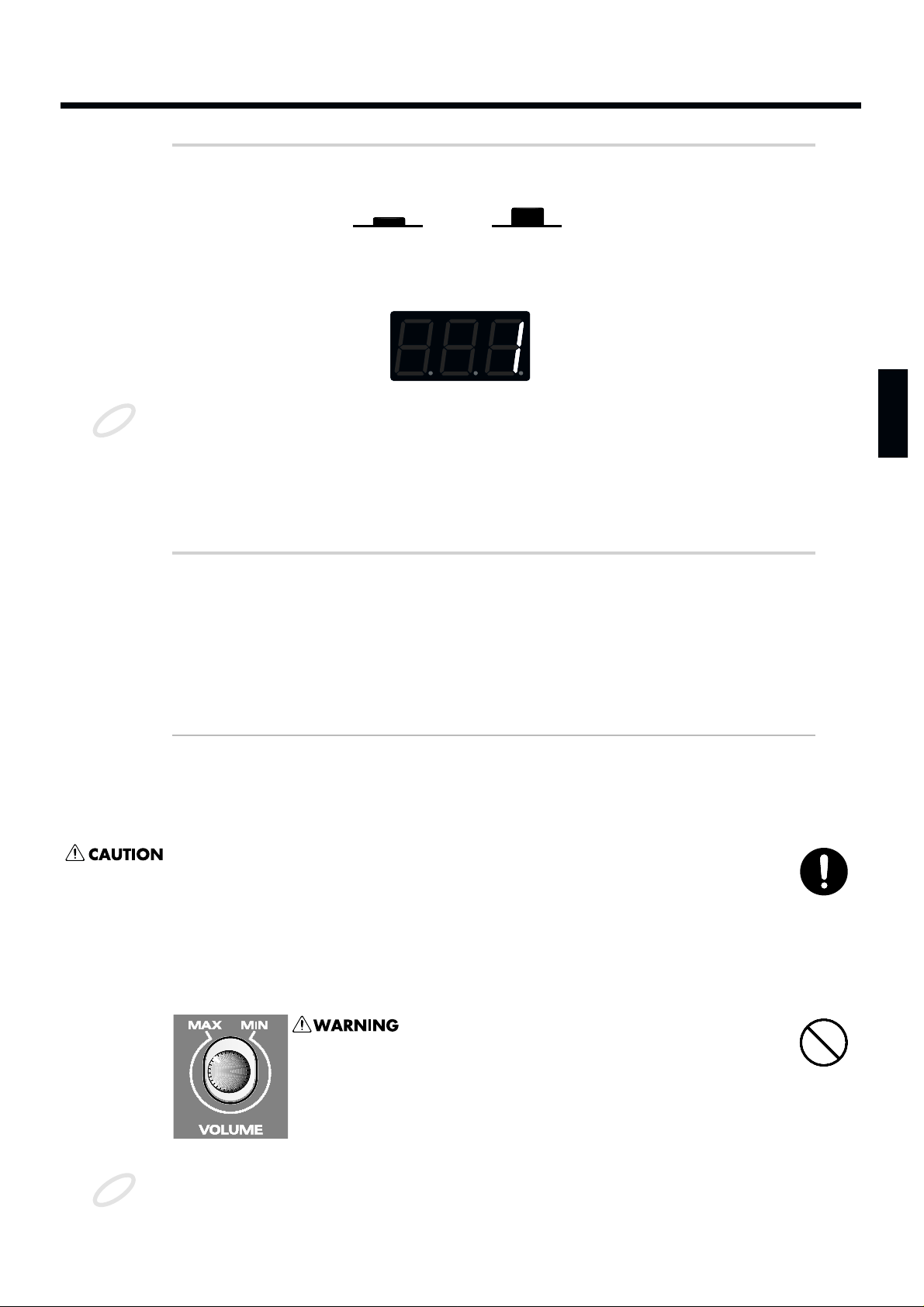
2
Press the power switch to turn the unit on.
fig.7
When the power is turned on, the SPD-20 will be in the Play mode. This is the mode in
which you will play the SPD-20.
fig.8
When you turn the SPD-20’s power on, it takes about one second complete adjustments to the trigger
circuits.
After you turn the power on, do not strike the pads or press the pedals until the Patch number is displayed.
If you turn the power on when a hi-hat control pedal (FD-7) is connected, make sure that the pedal is
fully open. When you turn the power on, a message “Fd7” will be displayed briefly. (For details see p.
40.) Do not press the pedal until this message has been displayed.
3
Turn on the other devices, but turn the power amp on last.
Turning the Power Off
Power down your system in the reverse order.
When the power is turned off, the following three functions will be reset to their factory settings.
Function Factory setting
Local Control (p. 72) On
HH Control Pedal (p. 40) Not set
PATCH CHAIN ON/OFF Off
Functions and parameter settings other than these are retained even when the power is turned off.
Whenever the unit is to remain unused for an extended period of time, disconnect the AC adaptor.
Adjusting the Volume
When you strike a pad, it will trigger the sound that has been assigned to it. Playing harder will produce a louder sound. As you play, adjust the overall volume by rotating the VOLUME knob located on
the rear panel.
fig.9
This unit, either alone or in combination with an amplifier
and headphones or speakers, may be capable of producing
sound levels that could cause permanent hearing loss. Do
not operate for a long period of time at a high volume level,
or at a level that is uncomfortable. If you experience any
hearing loss or ringing in the ears, you should immediately
stop using the unit, and consult an audiologist.
To avoid disturbing your neighbors, try to keep the unit’s volume at reasonable levels. You may prefer
to use headphones, so you do not need to be concerned about those around you (especially when it is
late at night).
On
Off
NOTE
NOTE
13
1
2
3
4
5
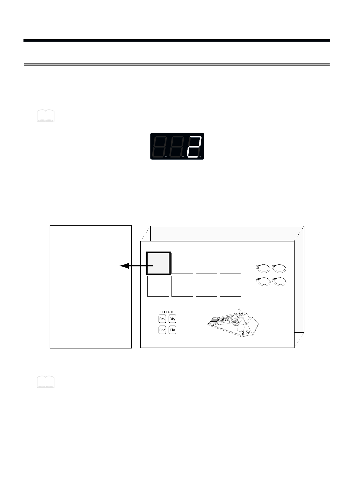
Selecting a Patch
When you select a Patch, the sound assigned to each pad and the settings for MIDI, effect and pedal will
all change instantly. Try each of the 99 factory-preset Patches to hear the different possibilities.
To select Patches first make sure you are in the Play mode. Then use the PATCH/VALUE [-] or [+] buttons to select Patches. The number of the selected Patch will appear in the display.
Pressing PATCH/VALUE [+] while holding down PATCH/VALUE [-] (or vice versa) causes the
Patch numbers to change more rapidly.
fig.10
The factory patch names are listed on p. 93.
What is a Patch?
A Patch contains data determines how each pad sounds, settings for the effects and also MIDI settings.
The SPD-20 can store 99 different Patches.
fig.11
When you select a Patch, the settings for each pad are instantly changed (p. 15).
You can also use MIDI Exclusive messages to store Patch data in an external sequencer or other
device (p. 75).
MEMO
Pad 2
External Pads
1-4
Pad 3 Pad 4
Pad 6Pad 5 Pad 7 Pad 8
Internal Pads 1-8
+
Patch 99
Patch 1
Sound Parameters
• Instrument
• Level
• Pitch
• Decay
• Pan
• Velocity Curve
• Effect Send
MIDI Parameters
• Transmit Channel
• Note Number
• Gate Time
• Pan
• Velocity Curve
• Velocity Sensitivity
• Program Change
Pad 1
•
•
Hi-Hat Control PedalEffects
Pad 1
MEMO
14
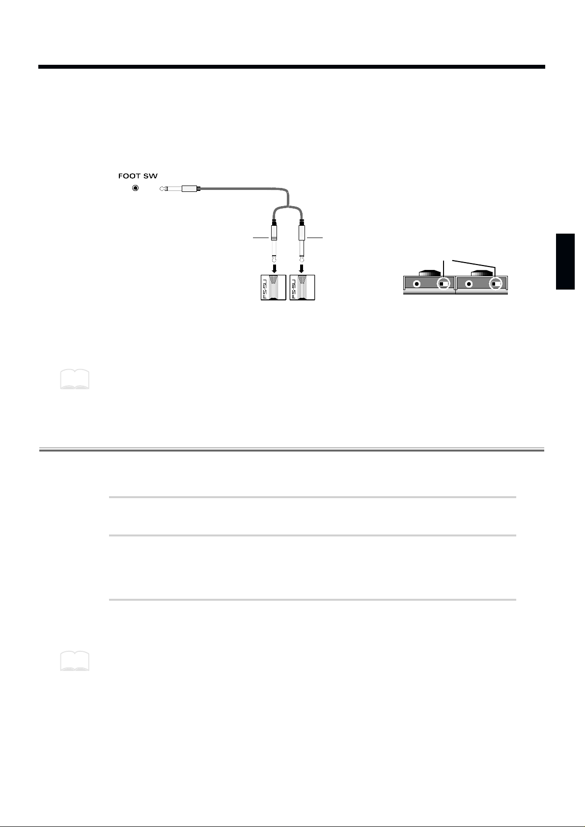
Using a Footswitch to Select Patches
By using a special cable (PCS-31; sold separately) to connect two footswitches (FS-5U; sold separately)
to the FOOT SW jack, you can select Patches by remote control. When you press Footswitch 1 you will
advance to the next Patch number, and when you press Footswitch 2 you will go back to the previous
Patch number. If you connect a DP-2, you can move up (but not down) through the Patch numbers.
fig.12
Connect the two mono cables of the PCS-31 to the two footswitches. The plug with the white line is for
Footswitch 1, and the plug with the red line is for Footswitch 2.
Connecting the model DP-2 pedal switch (sold separately) allows you to only advance the Patch numbers.
When using the footswitch as a Hold Pedal, please refer to “Using a Footwitch as a Hold Pedal” on p. 41.
Comparing Layered Sounds
Most of the factory-preset Patches use Layer (p. 17). Select a layered Patch and listen to the sounds of
pad banks A and B. When you select a layered Patch, both PAD BANK indicators (A and B) will light.
1
Select a Patch.
2
In the Play mode, press [LAYER] to turn Layer off.
PAD BANK indicator B will go out. Now you can play the pads to hear the sound of pad
bank A.
3
To hear the sound of pad bank B, press [BANK A/B] so that PAD
BANK indicator B lights. Play the pads.
Each time you press [BANK A/B], PAD BANK indicators A and B will light alternately.
Footswitch 2
(Previous Patch) (Next Patch)
Footswitch 1
(White)
(Red)
Stereo
MonoMono
POLALITY
You can make the setting with
the FS-5U polarity switch, as
shown in the figure below.
MEMO
MEMO
15
1
2
3
4
5
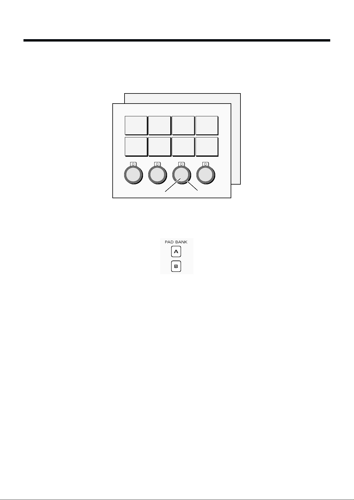
What is a Pad Bank?
The 8 pads of the SPD-20, together with 4 external pads (plus the 4 rims)—for a total of 16 pads—are
referred to as a pad bank. Each Patch contains two pad bank settings, A and B.
fig.13
When you select a Patch, the PAD BANK indicator will show which pad bank the Patch uses. If the
Layer function (explained below) is used in that Patch, both PAD BANK indicators (A and B) will be lit.
fig.14
Pad Bank B
Pad Bank A
Pad 2
4 Rims4 External Pads
Pad 1 Pad 3 Pad 4
Pad 6Pad 5 Pad 7 Pad 8
16
What is the Layer Function?
Layer means that two sounds are played simultaneously. The Layer setting is stored as part of each
Patch. A Patch for which Layer is enabled will simultaneously play the sounds of both pad banks (A
and B). In this case, however, you will only be able to play half as many notes simultaneously (a maximum of 7). Layering sounds can open the door to creative expression.
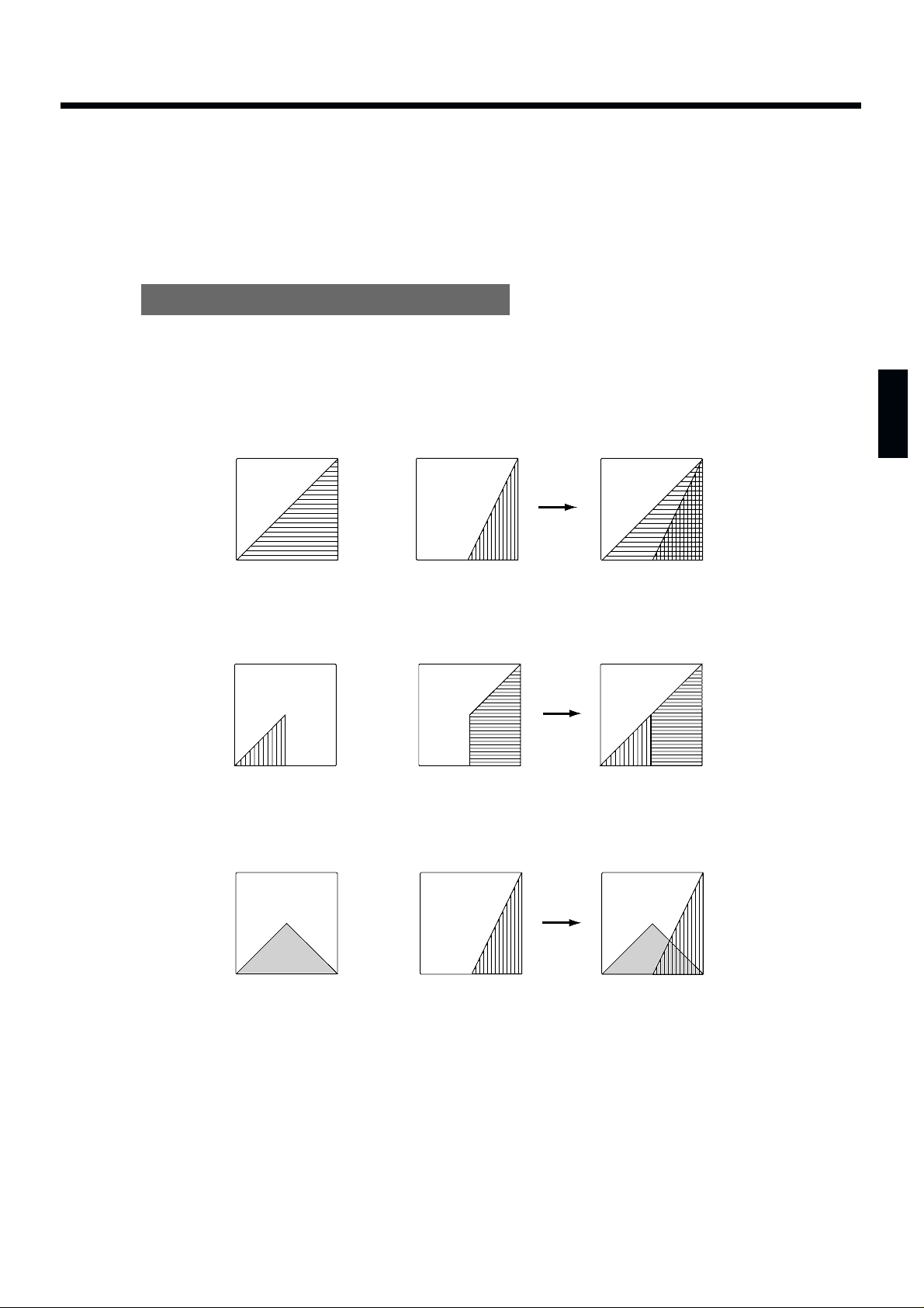
Ways to use the Layer function
By assigning different Instruments to pad banks A and B, and setting pad banks A and B to different
Velocity Curves (p. 24), your playing dynamics can be used to cross-fade or switch between the two
sounds.
Velocity Mix: Playing dynamics will determine the mix of the two sounds.
fig.15-a
Velocity Switch: Playing dynamics cause a switch between the two sounds.
fig.15-b
Velocity Crossfade: Playing dynamics produce cross-fades between the two sounds.
fig.15-c
+
Velocity
Volume
Pad Bank A
Pad Bank B
+
Velocity
Volume
Pad Bank A
Pad Bank B
+
Velocity
Volume
Pad Bank A
Pad Bank B
17
1
2
3
4
5
About the SPD-20’s Internal Setup and Parameter Settings (Edit)
This Chapter explains the basic structure of the SPD-20 and how it functions. Before we get into details,
you should have an overall understanding of the unit.
What Kind of Instrument is the SPD-20?
The SPD-20 is an electronic percussion instrument that produces sound when its pads are struck. This
type of device is usually called a MIDI pad controller. The SPD-20 includes a sound generator (700
sounds with 16-bit dynamic range) and digital effects unit in a compact and lightweight package. By
connecting external pads or pedals (sold separately), you can obtain the same musical expressivity from
the SPD-20 as you might enjoy with an acoustic drum kit. In addition, the SPD-20 is MIDI compatible,
meaning that it can be connected to any other MIDI-compatible device (sequencer, sampler, etc.) regardless of the manufacturer. This allows you to create a very powerful music system.
Product Overview
• Self-contained compact MIDI pad controller
• 8 dynamics-sensitive pads
• 700 sounds with 16-bit dynamic range
• Built-in digital effects
• Expandable with external pads/pedals
(such as the PD-7, PD-120, KD-7, and FD-7)
• Teams up with various MIDI units
(such as sequencer, sampler, etc.)
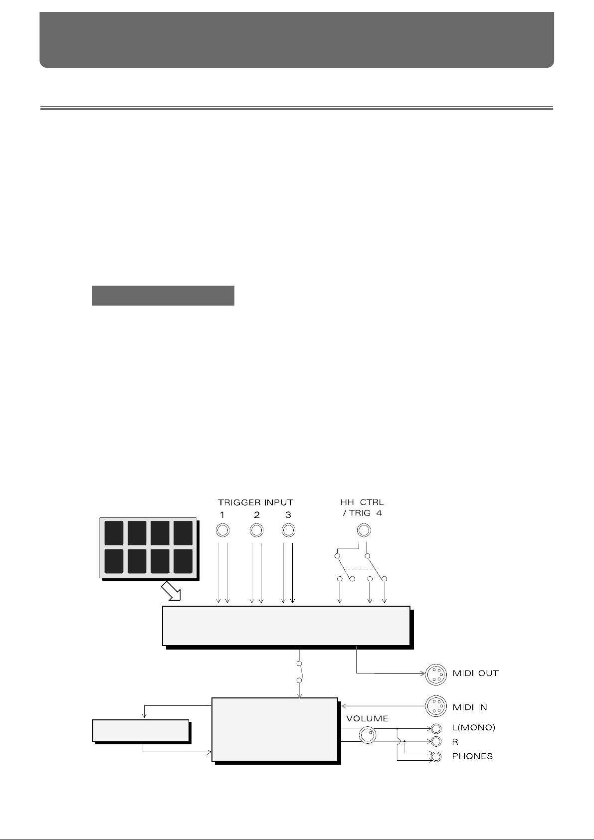
Internal Organization
The SPD-20 can be divided into the following sections:
fig.16
Trigger Interface section
Head
Rim
Head
Rim
Head
Rim
Head
HH CTRL
Rim
Pad section
Sound Generating
section
Effects section
FX SEND
FX LEVEL
Local Control
On/Off
CHAPTER 2 Using the SPD-20 by Itself
18
Pad section
This section has 8 velocity sensitive pads that respond to changes in your playing dynamics.
Trigger Interface section
This section sends the trigger signals (electric signals produced when you strike a pad) to the Sound
Generating section.
Sound Generating section
This section receives signals from the trigger interface or MIDI IN, and produces sound in response. The
SPD-20 contains 700 sounds and up to 14 can be played simultaneously.
Effects section
This section adds effects (Flanger, Chorus, Reverb, Delay) to the sound from the sound generator. You
can select from 25 effects combinations (p. 28).
Play Mode and Edit Mode
The SPD-20 has two modes; the Play mode and the Edit mode. Press [EDIT] to switch between them.
fig.17
Play Mode
In this mode you can strike the pads and select Patches. In the Play mode, the display will show the
Patch number.
Edit Mode
In this mode you can make settings for the various parameters. In the Edit mode, the display will show
the parameter value (which will be flashing).
In addition to these two modes, there is another, the Advanced Edit mode, for making more detailed
settings for the Trigger parameters. (p. 48)
EDIT
Edit Mode
Play Mode
(the display is flashing)
(the display is lit)
MEMO
19
1
2
3
4
5
How to Edit
To modify parameter values you must be in the Edit mode. The names of all the parameters you can
modify are in the Parameter List printed on the front panel.
“Edit” refers to the process of changing parameter values.
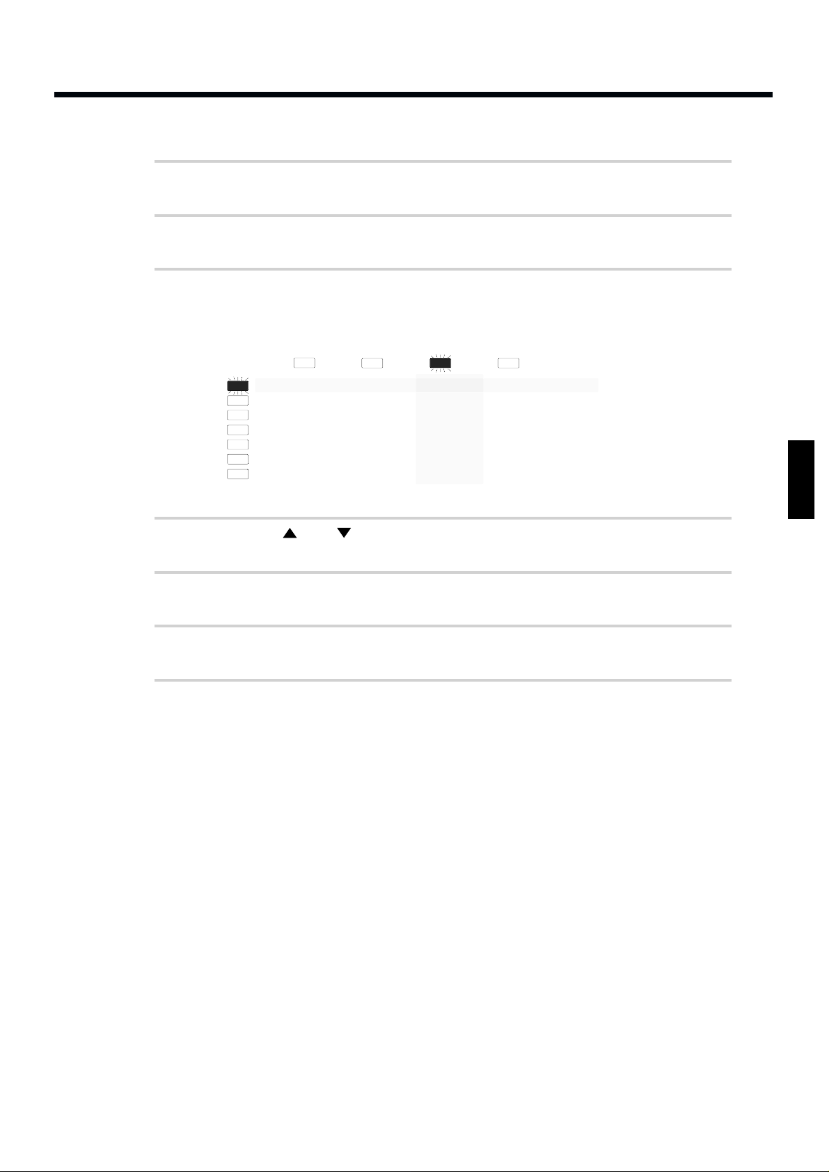
How to read the parameter list
The parameter list has four indicators arranged horizontally and seven indicators arranged vertically. In
the Edit mode, one of the horizontal indicators and one of the vertical indicators will always be lit. This
shows which parameter is being edited; i.e., the intersection of the indicated column and row is the currently selected parameter. The display shows the value of this parameter. To edit a particular parameter, refer to the parameter list and use the [SELECT] and [ ] [ ] buttons to select it.
fig.18
Use PATCH/VALUE [-] or [+] to modify the parameter value.
MEMO
Selected Parameter
Value (flashing)
The intersection of the
indicated column and row
TX CH
NOTE #
GT TIME
PAN
CURVE
SENS
PGM CHG
INST
LEVEL
PITCH
DECAY
PAN
CURVE
FX SEND
FX TYPE
FX TIME
FX LEVEL
PDL CTRL
PDL LEVEL
PDL CC #
BASIC CH
BULK DUMP
PATCH EXPAND
TRIG SENS
TRIG THRESHOLD
TRIG TYPE
TRIG CURVE
can be set
to each pad
can be set to
each Patch
can be set to
the entire system
MEMO
20
How to edit
1
Press [EDIT] to enter the Edit mode.
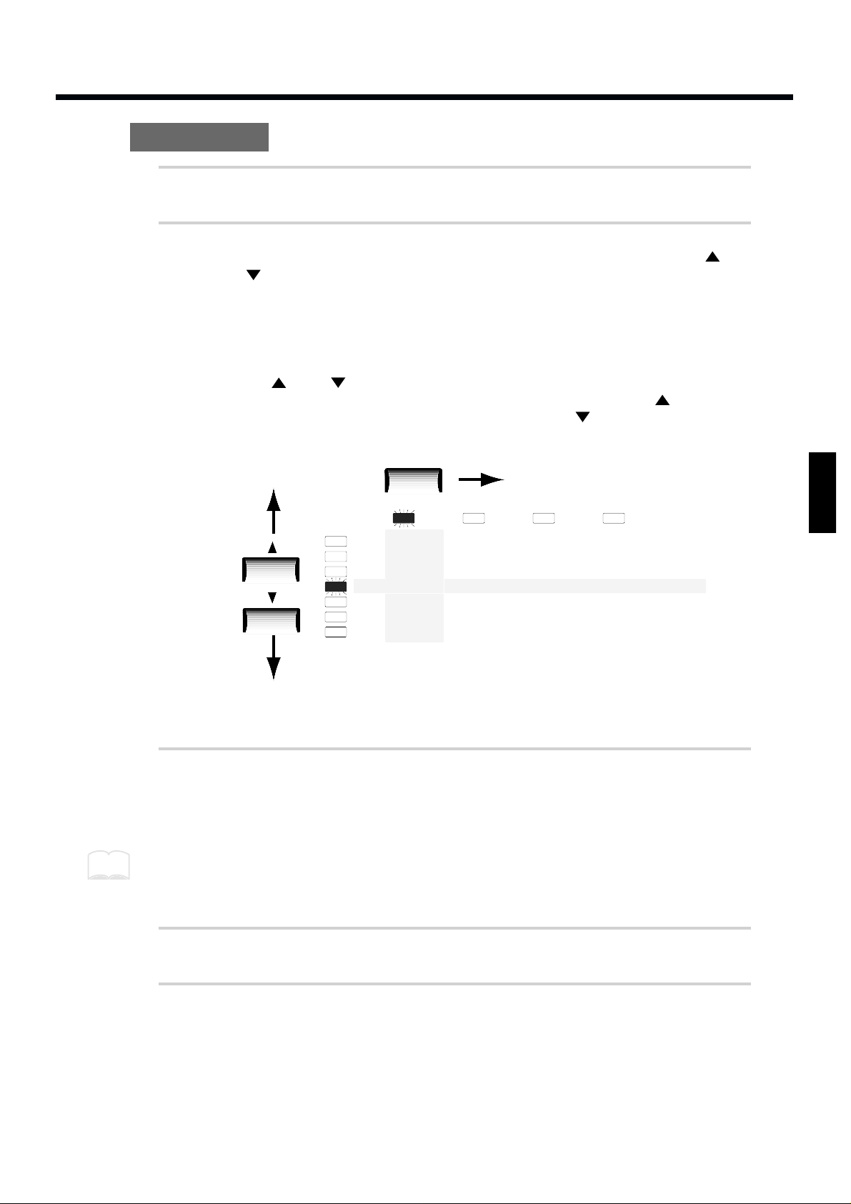
2
Select the parameter you wish to edit. Press [SELECT] to get the
appropriate indicator to light, thus selecting a column. Use [ ] or
[ ] to select the desired row, by getting the appropriate indicator
to light. (The display will show the value of the selected parameter.)
[SELECT] chooses the parameter group. The parameters of the SPD-20 are organized into
four groups: SOUND, MIDI, FX/PEDAL, and SYSTEM. With each press of [SELECT], the
indicator that lights (and the group that is selected), will be the next one in this group.
The [ ] and [ ] buttons are used to select parameters within the parameter groups.
The indicator above the currently lighted one will light when you press [ ], and the one
below the one currently lighted will light when you press [ ].
fig.19
In this illustration, the DECAY parameter in the SOUND parameter group is selected.
3
Use PATCH/VALUE [-] or [+] to set the value. The previous value of
the parameter will be discarded. In the case of a numerical value,
PATCH/VALUE [+] increases the value, and PATCH/VALUE [-]
decreases it.
You can speed up the change in values by pressing [+] while holding down [-] (or vice versa).
4
If you wish to edit another parameter, repeat steps 2–3 as necessary.
5
Press [EDIT] to return to the Play mode.
The parameter list indicators will go out, and the display will once again show the Patch
number.
TX CH
NOTE #
GT TIME
PAN
CURVE
SENS
PGM CHG
FX TYPE
FX TIME
FX LEVEL
PDL CTRL
PDL LEVEL
PDL CC #
BASIC CH
BULK DUMP
PATCH EXPAND
TRIG SENS
TRIG THRESHOLD
TRIG TYPE
TRIG CURVE
INST
LEVEL
PITCH
DECAY
PAN
CURVE
FX SEND
SELECT
MEMO
21
1
2
3
4
5
Selecting and Adjusting Sounds (Sound Parameters)
The parameters in the SOUND group (the sound parameters) allow you to modify the sound assigned
to each pad.
The SOUND group contains 7 parameters: INST, LEVEL, PITCH, DECAY, PAN, CURVE and FX SEND.
Sound parameter settings for each pad are stored in each Patch.
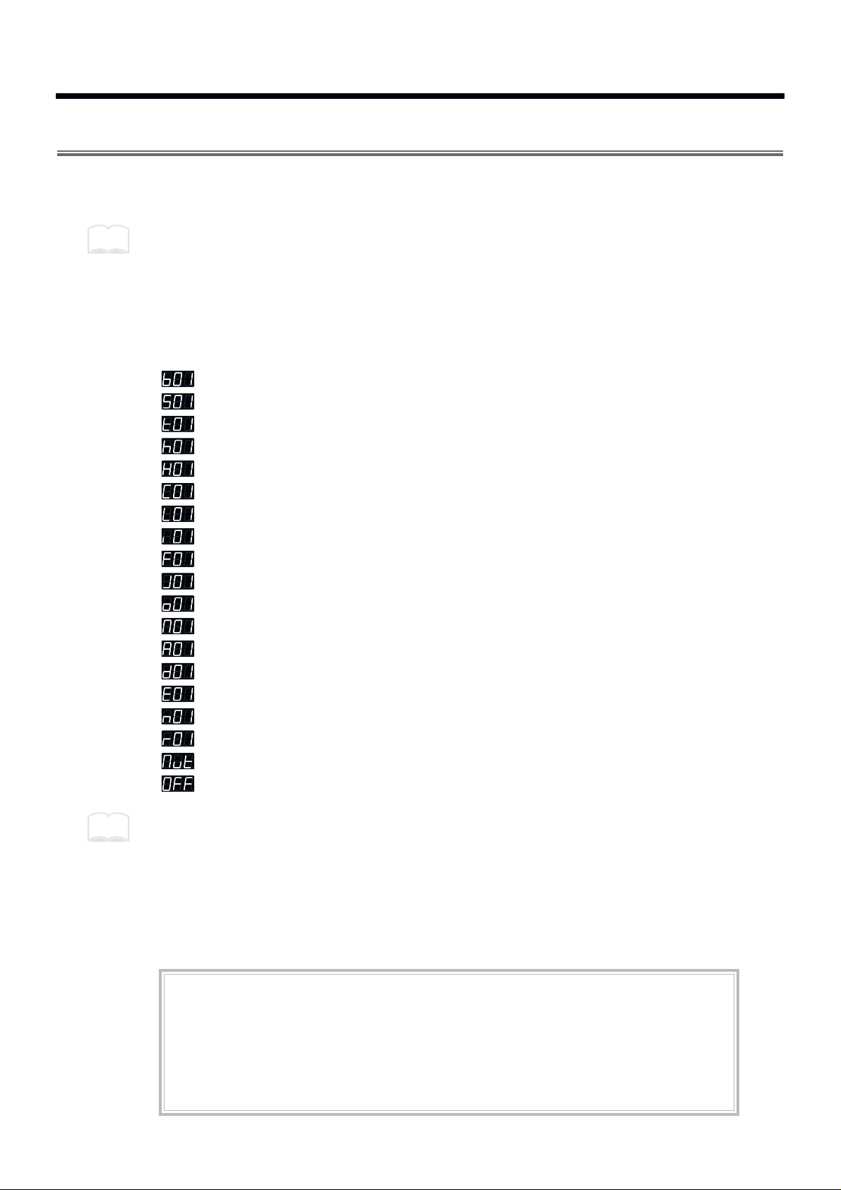
Selecting a Sound (INST)
Each sound assigned to a pad is called an Instrument. The SPD-20 contains 700 such Instruments, and
the Instrument assign settings determine which sounds will be played. The 700 Instruments are
grouped into the following categories.
fig.96
b01 – b50 Bass Drum
S01 – S86 Snare Drum
t01 – t40 Tom-tom
h01 – h33 Hi-Hat Cymbal
H01 – H17 Hi-Hat Cymbal for pedal control
C01 – C36 Crash/Ride Cymbal
L01 – L78 Latin Percussion (Cuban, Brazilian)
i01 – i33 Indian Percussion
F01 – F37 African/Middle Eastern/Australian/Other Percussion
J01 – J51 Japanese/Korean/Chinese/Southeast Asian Percussion
o01 – o24 Orchestral Percussion
M01 – M59 Melodic Percussion/Melodic Instrument
A01 – A16 Analog Percussion (CR-78, TR-808, etc.)
d01 – d43 Dance Sounds
E01 – E46 Artificial Sound Effects
n01 – n31 Natural Sounds, Human Voice
r01 – r20 Ambience, Reversed Sounds
Mut Forces Phrase Loop Instrument to stop (MUTE). No sound
oFF No sound
The Hi-Hat Cymbals for pedal control “instruments H01–H17” can be used effectively only when a
Hi-Hat controller (FD-7; separately sold) is used (p. 54).
If the Instrument assign setting for any Pad is set to “oFF”, there will be no sound when you strike
that Pad.
If you make the Hold Pedal settings (p. 41), then with some of the sounds, you can use the footswitch
to sustain the sound. For the instruments that can be lengthened with the footswitch, refer to p. 88.
When an Instrument is selected, by pressing PATCH/VALUE [+] while holding down [-] (or vice
versa), you can jump to the next Instrument group.
MEMO
MEMO
About Phrase Loop
Some Instruments are designed as Phrase Loops (p. 88).
When you select a Phrase Loop, you don’t just hear single notes; instead, a short phrase typical of
that musical genre is played. You cannot play more than one Phrase Loop on different pads. You
can layer two Phrase Loops on one pad and play them simultaneously. To force a Phrase Loop to
stop sounding, select “Mut” and strike the pad. No sound is heard from a pad that has been set for
“Mut.”
22
Adjusting the Volume (LEVEL)
This parameter determines the volume (0–15). At a setting of 0 there will be no sound.
When FX SEND in the SOUND parameter group is set above 0, the effects sound alone will be heard
even if the LEVEL parameter is set to 0.
Adjusting the Pitch (PITCH)
This parameter determines the pitch of the Instrument (-24–+24). Each step will change the pitch by a
semitone (100 cents).
For some Instruments, raising the pitch beyond a certain point will not be possible.
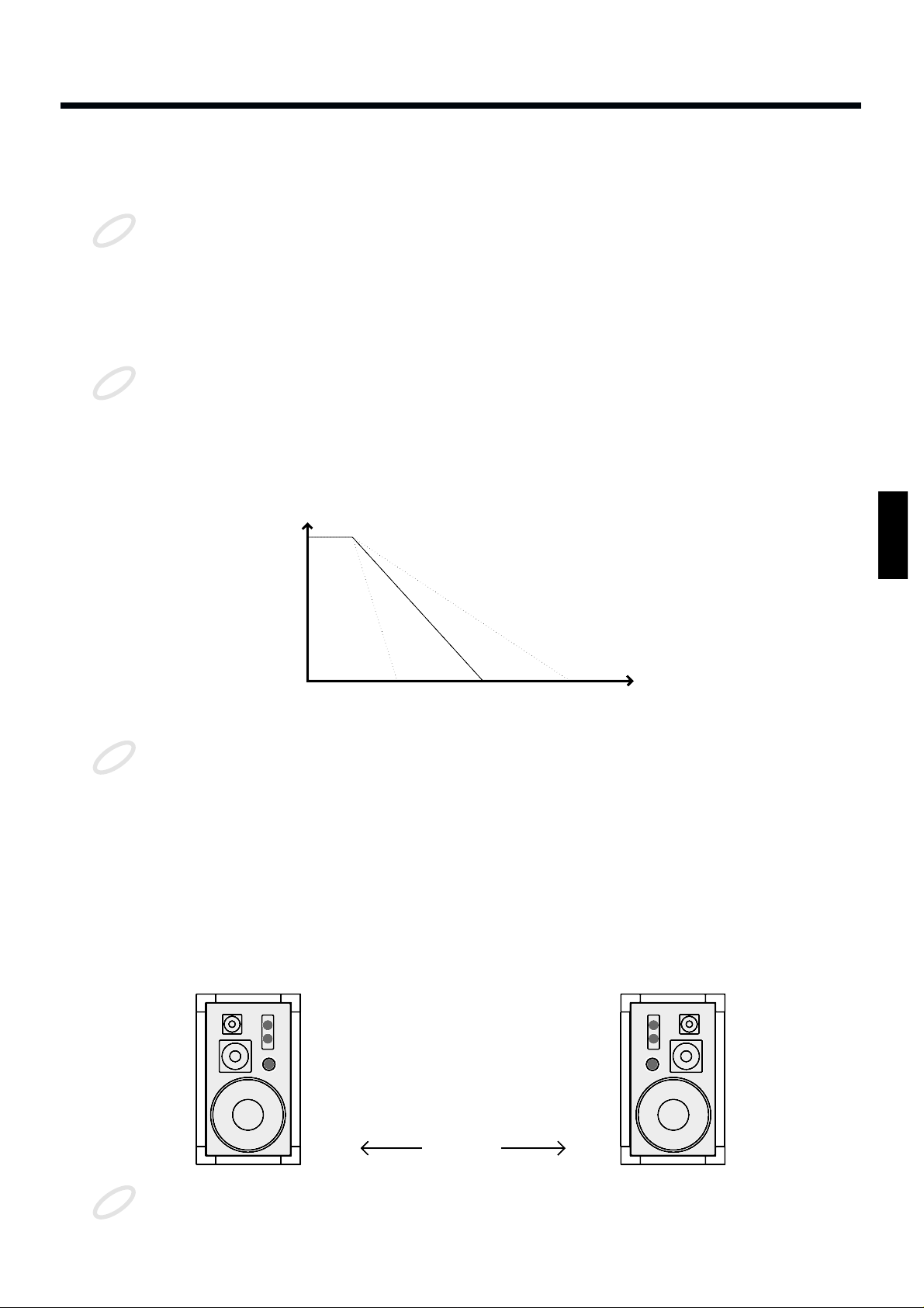
Adjusting the Decay (DECAY)
This parameter adjusts the decay of the Instrument (-31–+31). Higher settings will result in a longer
decay time.
fig.20
For some Instruments, raising the decay beyond a certain point will not be possible.
When the connected pedal is assigned to “HH” (p. 54), the decay parameter has no effect on Hi-Hat
Cymbals for pedal control (instruments H01–H17).
Changing the decay setting for a Phrase Loop Instrument (p. 88) changes the attenuation time at the
end of the loop.
Adjusting the Stereo Position (PAN)
This parameter determines the stereo position of the Instrument (L7–Ctr–r7/rnd). A setting of L7 is far
left, Ctr is center, and r7 is far right. At the “rnd” setting, the stereo position will change randomly each
time you strike the pad.
fig.21
This parameter is meaningful only when the SPD-20 is connected to a stereo audio system.
NOTE
NOTE
Level
Time
310-31
NOTE
Right SpeakerLeft Speaker
Ctr
(Center)
L7 r7
NOTE
23
1
2
3
4
5
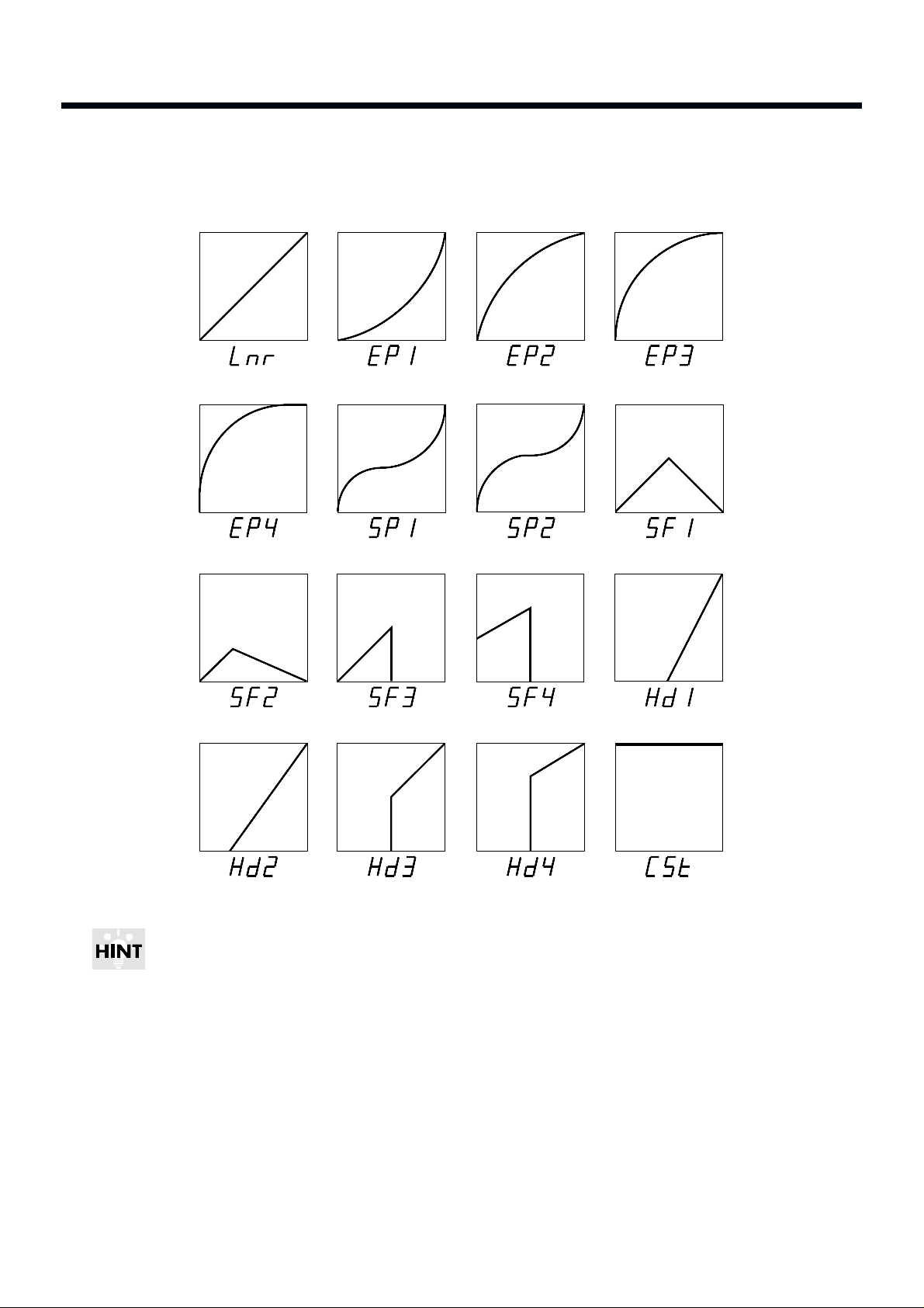
Adjusting the Dynamic Volume Response (CURVE)
This parameter determines how the Instrument volume will change in response to your playing. You
can choose from 16 response curves.
fig.22
You can come up with some effective Layered sounds by combining SF (Soft) and Hd (Hard) Velocity
Curves.
Ex. 1: In a layered patch, when you combine SF1 and Hd1, or SF2 and Hd2, as the Velocity Curve
settings for pad bank A and pad bank B, respectively, striking the pad lightly sounds the
Instrument of pad bank A, and the harder you hit, the louder you can make the sound of the
pad bank B Instrument become (Velocity Crossfade).
Ex. 2: In a layered patch, when you combine SF3 and Hd3, or SF4 and Hd4, as the Velocity Curve
settings for pad bank A and pad bank B, respectively, you can switch the pad bank A and pad
bank B Instruments with the strength with which you strike the pads (Velocity Switch).
Exponential 1 Exponential 2 Exponential 3 Linear
Spline 1 Soft 1
Exponential 4
Spline 2
Hard 1Soft 4
Hard 3 Constant
Hard 2
Hard 4
Soft 2 Soft 3
24

fig.23 fig.24
When CSt is selected, the unit sounds at maximum volume, regardless of how hard you strike the pad.
Adjusting the Effects Depth (FX SEND)
This parameter determines the depth (0–15) of the effect applied to each Instrument assigned to the pad.
Higher settings will result in a deeper effect. With a setting of 0 there will be no effect. The overall
effects level for a Patch is determined by FX LEVEL in the FX/PEDAL parameter group.
fig.25
This FX SEND parameter will have an audible result only if the [FX ON/OFF] setting is on, and FX
LEVEL in the FX/PEDAL parameter group is set above 0.
+
Pad Bank A
Pad Bank B
Velocity Crossfade
Velocity Switch
Hard 1Soft 1
Hard 3Soft 3
+
Pad Bank A
Pad Bank B
MEMO
FX SEND
Sound Generating
section
Effects section
PAN
LEVEL
L/MONO
R
OUTPUT
FX LEVEL
NOTE
25
1
2
3
4
5
How to Edit Sound Parameters
It is not possible to simultaneously edit the sound parameters of pad banks A and B. Use [BANK A/B]
to switch between the two pad banks, and edit each bank separately.
Editing a sound parameter
1
In the Play mode, use the PATCH/VALUE [-] or [+] buttons to select
the Patch (1–99) to edit.
2
Press [EDIT] to enter the Edit mode.
Selecting and changing parameters is called editing.
3
Strike the pad you wish to edit.
4
Turn Layer on or off if necessary.
You can have only one of the Pad Bank Instruments sound by setting Layer to OFF.
5
Press [BANK A/B] to select the bank you wish to edit.
The selected PAD BANK indicator will be flashing.
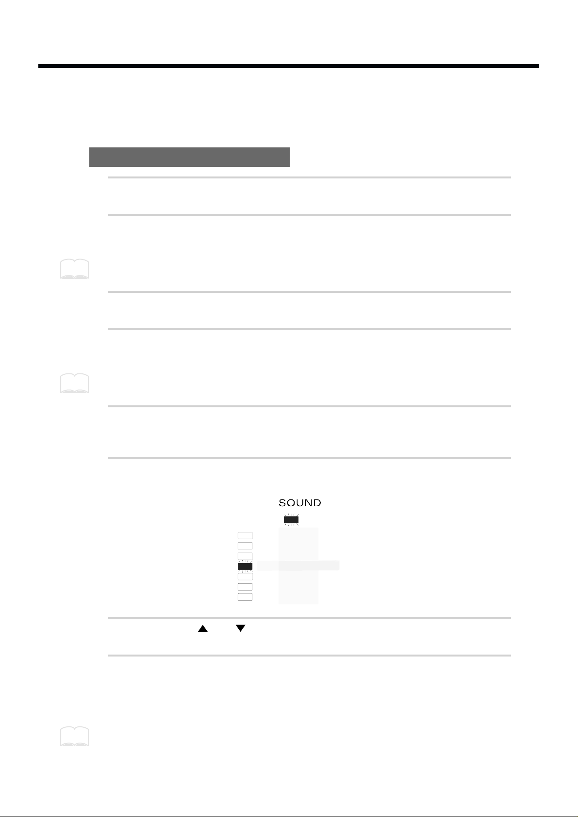
6
Press [SELECT] to select the SOUND parameter group.
fig.26
7
Press [ ] or [ ] to select the parameter to be edited.
8
Use PATCH/VALUE [-] or [+] to set the value.
For a numerical parameter, pressing PATCH/VALUE [-] will decrease the value, and
pressing PATCH/VALUE [+] will increase the value.
Pressing PATCH/VALUE [+] while holding down PATCH/VALUE [-] (or vice versa) makes this
change more rapidly. However, when selecting a Parameter Group Instrument (INST), when you
press PATCH/VALUE [+] while holding down PATCH/VALUE [-] (or vice versa), you jump to the
next Instrument group.
MEMO
MEMO
INST
LEVEL
PITCH
DECAY
PAN
CURVE
FX SEND
MEMO
26
9
To edit the other pad bank of the layered sound, repeat steps 5–8.
10
When you finish making settings, press [EDIT] to return to the Play
mode.
By using a special cable (PCS-31; sold separately) to connect two footswitches (FS-5U; sold separately) to the FOOT SW jack, you can change parameter values by remote control. While in Edit Mode,
when you press Footswitch 1 you will advance to the next higher parameter value, and when you press
Footswitch 2 you will go down to the next lower parameter value (p. 15). If you connect a single
footswitch (DP-2; sold separately) you can only move up to a higher parameter value, not down to a
lower parameter value.
Setting all pads to the same parameter value
If you press [ALL/ENTER] after step 8, the displayed parameter value will be set for all pads of the currently selected pad bank.
fig.27
If you are making settings for one of the SPD-20’s pads, the settings will be applied to all 8 pads. If
you are making settings for an external pad, the settings will be applied to all 4 of the external pads,
and all 4 of the external rims.
By assigning the same Instrument to all the pads and setting a different pitch for each, you can play
melodies. The following procedure is an example using a melodic percussion Instrument (M01–M59).
1. Set the INST parameter in the SOUND parameter group to the desired Instrument.
2. Press [ALL/ENTER] to set all pads to the same sound.
3. Adjust the PITCH parameter for each pad.
MEMO
MEMO
27
1
2
3
4
5
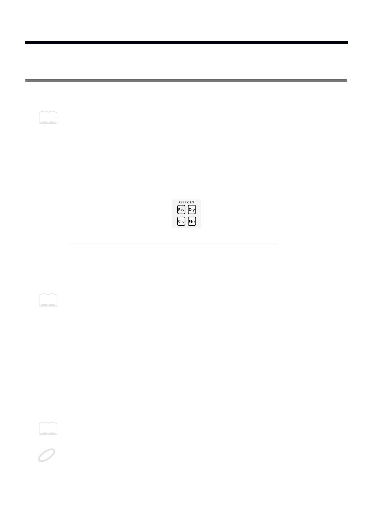
Adding Reverberation and Other Effects to the Sound
(Effect Parameters)
The SPD-20 has four on-board effects: Reverb, Delay, Chorus, and Flanger. There are three effects parameters: FX TYPE, FX TIME and FX LEVEL.
Effects settings are stored independently for each Patch, so you can set up the ideal effects for each
Patch.
Chapter 5 includes a section on “Taking Advantage of the On-board Effects” (p. 79), and we suggest
that you read this as well.
Select an Effect (FX TYPE)
This parameter selects one of the 25 effects combinations (1–25).
The Effect Indicator for the selected effect type will light to show the effect being used.
fig.27-a
Effect Type Explanation
1–10 Reverb sound Adds reverberation to the sound
11–14 Chorus sound Adds breadth to the sound
15–17 Flanger sound Applies undulations to the sound
18–25 Delay sound Adds an echo-like effect
For details on each effect type, refer to the page 79.
The effects are toggled on/off with each press of [FX ON/OFF].
Setting Effect Duration and Rate (FX TIME)
This sets the duration of reverberation, or the modulation rate (1–32). The higher the value, the longer
the reverb duration, or the higher the modulation rate. The result will be different depending on the
type of effect. Refer to page 79.
Adjust the Effect Depth for the Entire Patch (FX LEVEL)
This parameter corresponds to the effect return level on a mixer, and higher settings will result in a
deeper effect (0–15). At a value of 0 there will be no effect.
The depth of the effect applied to each Instrument (assigned to a pad) is determined by FX SEND in
the SOUND parameter group. (p. 25)
This effect level parameter will have an audible result only if the [FX ON/OFF] setting is on, and if
the Instrument parameter FX SEND for a pad is set above 0.
MEMO
MEMO
MEMO
NOTE
28
How to Edit Effect Parameters
1
In the Play mode, use PATCH/VALUE [-] or [+] to select a Patch
(1–99).
2
Press [EDIT] to enter the Edit mode.
3
Press [SELECT] to select the FX/PEDAL parameter group (p. 21).
fig.28
4
Press [ ] or [ ] to select the effect parameter you wish to edit.
5
Use PATCH/VALUE [-] or [+] to set the value.
6
Repeat steps 3–5 to finish making the effect settings for the Patch.
7
If you wish to adjust the effect depth independently for each pad,
make the appropriate settings for the FX SEND in the SOUND parameter group for each pad (p. 25).
TX CH
NOTE #
GT TIME
PAN
CURVE
SENS
PGM CHG
BASIC CH
BULK DUMP
PATCH EXPAND
TRIG SENS
TRIG THRESHOLD
TRIG TYPE
TRIG CURVE
INST
LEVEL
PITCH
DECAY
PAN
CURVE
FX SEND
FX/PEDAL SYSTEMMIDISOUND
FX TYPE
FX TIME
FX LEVEL
PDL CTRL
PDL LEVEL
PDL CC #
29
1
2
3
4
5
Adjusting the Pad Sensitivity (TRIG SENS)
By adjusting the TRIG SENS in the SYSTEM parameter group you can adjust the sensitivity of the pad
when it is struck (the range of adjustment is 1–16). Higher settings result in higher sensitivity, so that
the pad will produce a loud volume even when struck softly. This parameter applies to all 8 pads.
Factory Trigger Sensitivity (TRIG SENS) settings for the internal pad reflect the average user´s pref-
erences. If these settings produce good results for you, then there is no need to change the Trigger
Sensitivity values.
This parameter is set for all 8 pads, i.e., the same value applies to all pads. However, this parameter
can be set independently for each connected external pad.
Trigger Sensitivity (TRIG SENS) settings are common to all patches.
1
Press [EDIT] to enter the Edit mode.
2
Press [SELECT] to select the SYSTEM parameter group.
3
Use [ ] or [ ] to select TRIG SENS.
fig.29
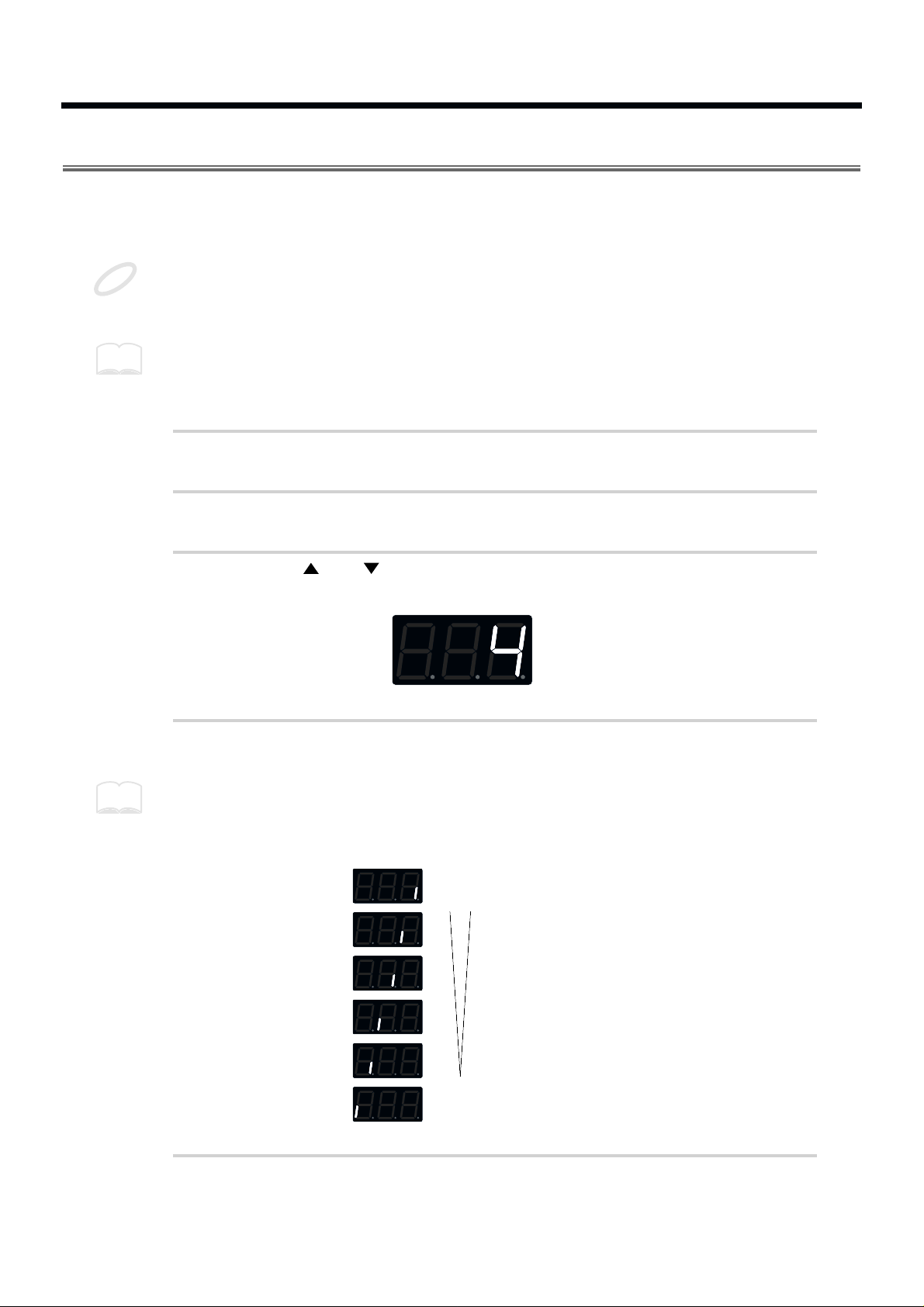
4
Strike one of the 8 pads.
When you strike the pad, the strength with which the pad is struck (velocity) is shown in the display
on a six-level scale. Striking the pad forcefully sets velocity at a value of 127.
fig.95
5
Use PATCH/VALUE [-] or [+] to set the value.
NOTE
MEMO
MEMO
Velocity
Strength
of Striking
Hard
127
100–126
75–99
50–74
25–49
1–24Soft
30
 Loading...