

Roland Corporation SD-80 Owner's Manual

Owner’s Manual
Thank you, and congratulations on your choice of the STUDIO Canvas SD-80.
Before using this unit, carefully read the sections entitled: “IMPORTANT
SAFETY INSTRUCTIONS” (Owner’s manual p. 2), “USING THE UNIT
SAFELY” (Owner’s manual pp. 3--4), and “IMPORTANT NOTES” (Owner’s
manual p. 5). These sections provide important information concerning
the proper operation of the unit. Additionally, in order to feel assured that
you have gained a good grasp of every feature provided by your new unit,
Getting started and Owner’s manual should be read in its entirety. The
manual should be saved and kept on hand as a convenient reference.
Copyright © 2002 ROLAND CORPORATION
All rights reserved. No part of this publication may be reproduced in any form
without the written permission of ROLAND CORPORATION.
CAUTION
This product complies with the requirements of European Directives EMC 89/336/EEC and LVD 73/23/EEC.
For EU Countries
For Canada
This Class B digital apparatus meets all requirements of the Canadian Interference-Causing Equipment Regulations.
Cet appareil numérique de la classe B respecte toutes les exigences du Règlement sur le matériel brouilleur du Canada.
NOTICE
AVIS
For the USA
FEDERAL COMMUNICATIONS COMMISSION
RADIO FREQUENCY INTERFERENCE STATEMENT
This equipment has been tested and found to comply with the limits for a Class B digital device, pursuant to Part 15 of the
FCC Rules. These limits are designed to provide reasonable protection against harmful interference in a residential
installation. This equipment generates, uses, and can radiate radio frequency energy and, if not installed and used in
accordance with the instructions, may cause harmful interference to radio communications. However, there is no guarantee
that interference will not occur in a particular installation. If this equipment does cause harmful interference to radio or
television reception, which can be determined by turning the equipment off and on, the user is encouraged to try to correct the
interference by one or more of the following measures:
– Reorient or relocate the receiving antenna.
– Increase the separation between the equipment and receiver.
– Connect the equipment into an outlet on a circuit different from that to which the receiver is connected.
– Consult the dealer or an experienced radio/TV technician for help.
This device complies with Part 15 of the FCC Rules. Operation is subject to the following two conditions:
(1) This device may not cause harmful interference, and
(2) This device must accept any interference received, including interference that may cause undesired operation.
Tested To Comply With FCC Standards
FOR HOME OR OFFICE USE
Unauthorized changes or modification to this system can void the users authority to operate this equipment.
This equipment requires shielded interface cables in order to meet FCC class B Limit.
RISK OF ELECTRIC SHOCK
DO NOT OPEN
ATTENTION: RISQUE DE CHOC ELECTRIQUE NE PAS OUVRIR
CAUTION: TO REDUCE THE RISK OF ELECTRIC SHOCK,
DO NOT REMOVE COVER (OR BACK).
NO USER-SERVICEABLE PARTS INSIDE.
REFER SERVICING TO QUALIFIED SERVICE PERSONNEL.
The lightning flash with arrowhead symbol, within an
equilateral triangle, is intended to alert the user to the
presence of uninsulated “dangerous voltage” within the
product’s enclosure that may be of sufficient magnitude to
constitute a risk of electric shock to persons.
The exclamation point within an equilateral triangle is
intended to alert the user to the presence of important
operating and maintenance (servicing) instructions in the
literature accompanying the product.
INSTRUCTIONS PERTAINING TO A RISK OF FIRE, ELECTRIC SHOCK, OR INJURY TO PERSONS.
IMPORTANT SAFETY INSTRUCTIONS
SAVE THESE INSTRUCTIONS
WARNING - When using electric products, basic precautions should always be followed, including the following:
1. Read these instructions.
2. Keep these instructions.
3. Heed all warnings.
4. Follow all instructions.
5. Do not use this apparatus near water.
6. Clean only with a dry cloth.
7. Do not block any of the ventilation openings. Install in
accordance with the manufacturers instructions.
8. Do not install near any heat sources such as radiators,
heat registers, stoves, or other apparatus (including
amplifiers) that produce heat.
9. Do not defeat the safety purpose of the polarized or
grounding-type plug. A polarized plug has two blades with
one wider than the other. A grounding type plug has two
blades and a third grounding prong. The wide blade or the
third prong are provided for your safety. When the provided
plug does not fit into your outlet, consult an electrician for
replacement of the obsolete outlet.
WARNING:
IMPORTANT:
As the colours of the wires in the mains lead of this apparatus may not correspond with the coloured markings identifying
the terminals in your plug, proceed as follows:
The wire which is coloured GREEN-AND-YELLOW must be connected to the terminal in the plug which is marked by the
letter E or by the safety earth symbol or coloured GREEN or GREEN-AND-YELLOW.
The wire which is coloured BLUE must be connected to the terminal which is marked with the letter N or coloured BLACK.
The wire which is coloured BROWN must be connected to the terminal which is marked with the letter L or coloured RED.
THIS APPARATUS MUST BE EARTHED
THE WIRES IN THIS MAINS LEAD ARE COLOURED IN ACCORDANCE WITH THE FOLLOWING CODE.
GREEN-AND-YELLOW: EARTH, BLUE: NEUTRAL, BROWN: LIVE
10. Protect the power cord from being walked on or pinched
particularly at plugs, convenience receptacles, and the
point where they exit from the apparatus.
11. Only use attachments/accessories specified by the
manufacturer.
12. Never use with a cart, stand, tripod, bracket,
or table except as specified by the
manufacturer, or sold with the apparatus.
When a cart is used, use caution when
moving the cart/apparatus combination to
avoid injury from tip-over.
13. Unplug this apparatus during lightning storms or when
unused for long periods of time.
14. Refer all servicing to qualified service personnel. Servicing
is required when the apparatus has been damaged in any
way, such as power-supply cord or plug is damaged, liquid
has been spilled or objects have fallen into the apparatus,
the apparatus has been exposed to rain or moisture, does
not operate normally, or has been dropped.
For the U.K.
DECLARATION OF CONFORMITY
Compliance Information Statement
Model Name :
Type of Equipment :
Responsible Party :
Address :
Telephone :
SD-80
Sound Module
Edirol Corporation North America
425 Sequoia Drive, Suite 114, Bellingham, WA 98226
(360) 594-4276
2
For the USA
USING THE UNIT SAFELY
Used for instructions intended to alert
the user to the risk of death or severe
injury should the unit be used
improperly.
Used for instructions intended to alert
the user to the risk of injury or material
damage should the unit be used
improperly.
* Material damage refers to damage or
other adverse effects caused with
respect to the home and all its
furnishings, as well to domestic
animals or pets.
001
• Before using this unit, make sure to read the
instructions below, and the Owner’s Manual.
................................................................................................
002a
• Do not open or perform any internal modifications on the unit.
................................................................................................
003
• Do not attempt to repair the unit, or replace
parts within it (except when this manual
provides specific instructions directing you
to do so). Refer all servicing to your retailer,
the nearest EDIROL/Roland Service Center,
or an authorized EDIROL/Roland
distributor, as listed on the "Information" page.
................................................................................................
004
• Never use or store the unit in places that are:
• Subject to temperature extremes (e.g.,
direct sunlight in an enclosed vehicle, near
a heating duct, on top of heat-generating
equipment); or are
• Damp (e.g., baths, washrooms, on wet
floors); or are
• Humid; or are
• Exposed to rain; or are
• Dusty; or are
• Subject to high levels of vibration.
................................................................................................
005
• This unit should be used only with a rack or
stand that is recommended by Roland.
................................................................................................
The symbol alerts the user to important instructions
or warnings.The specific meaning of the symbol is
determined by the design contained within the
triangle. In the case of the symbol at left, it is used for
general cautions, warnings, or alerts to danger.
The symbol alerts the user to items that must never
be carried out (are forbidden). The specific thing that
must not be done is indicated by the design contained
within the circle. In the case of the symbol at left, it
means that the unit must never be disassembled.
The ● symbol alerts the user to things that must be
carried out. The specific thing that must be done is
indicated by the design contained within the circle. In
the case of the symbol at left, it means that the powercord plug must be unplugged from the outlet.
006
• When using the unit with a rack or stand
recommended by Roland, the rack or stand
must be carefully placed so it is level and
sure to remain stable. If not using a rack or
stand, you still need to make sure that any
location you choose for placing the unit
provides a level surface that will properly
support the unit, and keep it from wobbling.
................................................................................................
007
• Make sure you always have the unit placed
so it is level and sure to remain stable. Never
place it on stands that could wobble, or on
inclined surfaces.
................................................................................................
008a
• The unit should be connected to a power
supply only of the type described in the
operating instructions, or as marked on the
unit.
................................................................................................
008e
• Use only the attached power-supply cord.
................................................................................................
3

009
• Do not excessively twist or bend the power
cord, nor place heavy objects on it. Doing so
can damage the cord, producing severed
elements and short circuits. Damaged cords
are fire and shock hazards!
................................................................................................
010
• This unit, either alone or in combination with
an amplifier and headphones or speakers,
may be capable of producing sound levels
that could cause permanent hearing loss. Do
not operate for a long period of time at a high
volume level, or at a level that is uncomfortable. If you experience any hearing loss or
ringing in the ears, you should immediately
stop using the unit, and consult an audiologist.
................................................................................................
011
• Do not allow any objects (e.g., flammable
material, coins, pins); or liquids of any kind
(water, soft drinks, etc.) to penetrate the unit.
................................................................................................
013
• In households with small children, an adult
should provide supervision until the child is
capable of following all the rules essential for
the safe operation of the unit.
................................................................................................
014
• Protect the unit from strong impact.
(Do not drop it!)
................................................................................................
015
• Do not force the unit’s power-supply cord to
share an outlet with an unreasonable number
of other devices. Be especially careful when
using extension cords—the total power used
by all devices you have connected to the
extension cord’s outlet must never exceed the
power rating (watts/amperes) for the
extension cord. Excessive loads can cause the
insulation on the cord to heat up and
eventually melt through.
................................................................................................
016
• Before using the unit in a foreign country,
consult with your retailer, the nearest
EDIROL/Roland Service Center, or an authorized EDIROL/Roland distributor, as listed
on the "Information" page.
................................................................................................
023
• DO NOT play a CD-ROM disc on a conventional audio CD player. The resulting sound
may be of a level that could cause permanent
hearing loss. Damage to speakers or other
system components may result.
................................................................................................
101a
• The unit should be located so that its location
or position does not interfere with its proper
ventilation.
................................................................................................
102b
• Always grasp only the plug on the powersupply cord when plugging into, or
unplugging from, an outlet or this unit.
................................................................................................
104
• Try to prevent cords and cables from
becoming entangled. Also, all cords and
cables should be placed so they are out of the
reach of children.
................................................................................................
106
• Never climb on top of, nor place heavy
objects on the unit.
................................................................................................
107b
• Never handle the power cord or its plugs
with wet hands when plugging into, or
unplugging from, an outlet or this unit.
................................................................................................
108a
• Before moving the unit, disconnect the power
plug from the outlet, and pull out all cords
from external devices.
................................................................................................
109a
• Before cleaning the unit, turn off the power
and unplug the power cord from the outlet.
................................................................................................
110a
• Whenever you suspect the possibility of
lightning in your area, pull the plug on the
power cord out of the outlet.
................................................................................................
118**
• Whenever you've removed any screws—
whether it be when connecting something to
the ground terminal, or when installing a
rack-mount adaptor or desk-stand mount—be sure
to place the screws out of reach of small children, so
they won't be swallowed accidentally.
4

IMPORTANT NOTES
291b
In addition to the items listed under “IMPORTANT
SAFETY INSTRUCTIONS” and “USING THE UNIT
SAFELY” on pages 2, 3 and 4, please read and
observe the following:
Power Supply
301
• Do not use this unit on the same power circuit with
any device that will generate line noise (such as an
electric motor or variable lighting system).
307
• Before connecting this unit to other devices, turn off
the power to all units. This will help prevent
malfunctions and/or damage to speakers or other
devices.
Placement
351
• Using the unit near power amplifiers (or other
equipment containing large power transformers)
may induce hum. To alleviate the problem, change
the orientation of this unit; or move it farther away
from the source of interference.
352a
• This device may interfere with radio and television
reception. Do not use this device in the vicinity of
such receivers.
352b
• Noise may be produced if wireless communications
devices, such as cell phones, are operated in the
vicinity of this unit. Such noise could occur when
receiving or initiating a call, or while conversing.
Should you experience such problems, you should
relocate such wireless devices so they are at a greater
distance from this unit, or switch them off.
355
• To avoid possible breakdown, do not use the unit in
a wet area, such as an area exposed to rain or other
moisture.
402
• Never use benzine, thinners, alcohol or solvents of
any kind, to avoid the possibility of discoloration
and/or deformation.
553
• Use a reasonable amount of care when using the
unit’s buttons, sliders, or other controls; and when
using its jacks and connectors. Rough handling can
lead to malfunctions.
554
• Never strike or apply strong pressure to the display.
555
•A small amount of noise may be heard from the
display during normal operation.
556
• When connecting / disconnecting all cables, grasp
the connector itself—never pull on the cable. This
way you will avoid causing shorts, or damage to the
cable’s internal elements.
557
•A small amount of heat will radiate from the unit
during normal operation.
558a
• To avoid disturbing your neighbors, try to keep the
unit’s volume at reasonable levels. You may prefer
to use headphones, so you do not need to be
concerned about those around you (especially when
it is late at night).
559a
• When you need to transport the unit, package it in
the box (including padding) that it came in, if
possible. Otherwise, you will need to use equivalent
packaging materials.
Handling CD-ROMs
801
• Avoid touching or scratching the shiny underside
(encoded surface) of the disc. Damaged or dirty CDROM discs may not be read properly. Keep your
discs clean using a commercially available CD
cleaner.
Maintenance
401a
• For everyday cleaning wipe the unit with a soft, dry
cloth or one that has been slightly dampened with
water. To remove stubborn dirt, use a cloth impregnated with a mild, non-abrasive detergent. Afterwards, be sure to wipe the unit thoroughly with a
soft, dry cloth.
5

Contents
USING THE UNIT SAFELY.......................................................3
IMPORTANT NOTES................................................................5
Contents ...................................................................................6
Introduction..............................................................................9
How to read this manual ....................................................................................................9
Main features........................................................................................................................9
Names of things and what they do.......................................10
Front Panel...............................................................................................................10
Rear Panel................................................................................................................12
Basic operation......................................................................13
Operations in the basic screen..........................................................................................13
Listening to the internal demo songs...................................................................13
Auditioning the sounds (Preview).......................................................................14
Adjusting the brightness of the display (Contrast)............................................15
Using the internal sound generator.....................................16
About the sound generator modes..................................................................................16
About GM2/Native modes ..............................................................................................17
GM2/Native mode sound sets.............................................................................17
About parts and sounds....................................................................................................18
Different types of part............................................................................................18
Polyphony and voices............................................................................................18
Specifying the function of the MIDI connectors............................................................19
USB mode ................................................................................................................19
MIDI mode ..............................................................................................................20
Specifying the function of the MIDI connectors............................................................21
Switching the sound generator mode.............................................................................22
Selecting a part ...................................................................................................................23
Selecting the type of part (INST/DRUM) ......................................................................24
Selecting the sound set......................................................................................................25
Selecting a sound................................................................................................................26
Selecting a drum set...........................................................................................................27
Muting/soloing a part.......................................................................................................28
Muting a part...........................................................................................................28
Soloing a part...........................................................................................................29
About parameters ..............................................................................................................30
Editing the parameters......................................................................................................31
Editing part parameters.........................................................................................31
Editing parameters that are common to all parts ..............................................32
About parameters that can be edited from the SD-80’s panel.....................................33
Part parameters (GM2 mode, Native mode) ......................................................33
Part parameters (Native mode)............................................................................37
Parameters common to all parts (GM2 mode, Native mode) ..........................38
6

Using the effects of the internal sound generator..............39
About the sound generator effects ..................................................................................39
Editing the sound generator effects.................................................................................40
Parameters that can be edited in GM2 mode.................................................................41
Reverb (System Effect)...........................................................................................41
Chorus (System Effect)...........................................................................................41
EQ (Equalizer).........................................................................................................42
Parameters that can be edited in Native mode..............................................................43
Reverb (System Effect)...........................................................................................43
Chorus (System Effect)...........................................................................................45
MFX (Multi-effects) ................................................................................................46
EQ (Equalizer).........................................................................................................48
System-related settings ........................................................49
Adjusting the contrast of the display..............................................................................50
Saving a patch.....................................................................................................................50
Switching the sound generator mode (Inst Initialize)..................................................50
Transmitting sound generator settings to an external MIDI device...........................50
Specifying the start-up sound generator mode.............................................................51
Setting the Device ID Number.........................................................................................51
Transmitting button/knob operations to an external MIDI device ...........................51
Preview settings .................................................................................................................52
Setting the system tempo..................................................................................................52
Switching the driver ..........................................................................................................52
Restoring the factory settings...........................................................................................52
Contents
Controlling the SD-80 via MIDI..............................................53
Controlling the internal sound generator.......................................................................53
Switching the sound generator mode..................................................................53
Switching the sound set.........................................................................................55
Switching the type of part .....................................................................................56
Switching sounds....................................................................................................58
Switching the drum set..........................................................................................61
Editing MIDI effect parameters............................................................................63
Writing/loading SD-80 settings ...........................................................................69
Troubleshooting.....................................................................71
Appendices.............................................................................75
Part parameter list..............................................................................................................75
Part parameters (GM2 mode, Native mode) ......................................................75
Part parameters (Native mode)............................................................................75
Parameters common to all parts (GM2 mode, Native mode) ..........................75
Parameters common to all parts (Native mode)................................................76
Effect parameter list...........................................................................................................77
Effect parameter (GM2 mode) ..............................................................................77
Effect parameter (Native mode)...........................................................................78
MFX parameter list ............................................................................................................80
Instrument list (GM2 / Native mode) ............................................................................95
Instrument list (Special sound)......................................................................................100
Instrument list (GS mode)...............................................................................................101
7

Contents
Instrument list (XGlite mode) ........................................................................................103
Drum set list (GM2 / Native mode)..............................................................................105
Classical set drum set (1).....................................................................................106
Classical set drum set (2).....................................................................................107
Contemporary set drum set (1)...........................................................................108
Contemporary set drum set (1)...........................................................................109
Solo set drum set (1).............................................................................................110
Solo set drum set (2).............................................................................................111
Enhanced set drum set (1)...................................................................................112
Enhanced set drum set (2)...................................................................................113
Drum set list (GS mode)..................................................................................................114
GS mode drum set (1) ..........................................................................................115
GS mode drum set (2) ..........................................................................................116
Drum set list (XGlite mode)............................................................................................117
XGlite mode drum set (1) ....................................................................................118
XGlite mode drum set (2) ....................................................................................119
XGlite mode drum set (3) ....................................................................................121
Specifications.......................................................................125
INDEX....................................................................................126
204
* Microsoft and Windows are registered trademarks of Microsoft Corporation.
206e
* Screen shots in this documents are reprinted with permission from Microsoft Corporation.
ADD
* Windows® XP is known officially as: “Microsoft® Windows® XP operating system.”
206f
* Windows® 2000 is known officially as: “Microsoft® Windows® 2000 operating system.”
206g
* Windows® Me is known officially as: “Microsoft® Windows® Millennium Edition operating system.”
206c
* Windows® 98 is known officially as: “Microsoft® Windows® 98 operating system.”
207
* Apple and Macintosh are registered trademark of Apple Computer, Inc.
209
* MacOS is a trademark of Apple Computer, Inc.
203
* GS ( ) is a registered trademark of Roland Corporation.
ADD
* XG ( ) and XGlite ( ) are trademarks of YAMAHA Corporation.
231
* OMS is a registered trademark of Opcode Systems, Inc.
232
* FreeMIDI is a trademark of Mark of the Unicorn, Inc.
220
* All product names mentioned in this document are trademarks or registered trademarks of their respective
owners.
8

Introduction
Thank you, and congratulations on your choice of the Edirol
How to read this manual
The documentation for the SD-80 consists of a
Information
• The
80 with your computer. Please read this first.
• The
settings for the SD-80 as described in the
correctly, refer to the Owner’s Manual as necessary, depending on the purpose you have in mind.
•
Additional Information
SD-80’s functionality. Read this material as necessary. In order to read the
file, you will need the
can be downloaded from the
(This URL may change without notice.)
• Letters and numbers enclosed in
• Areas enclosed by a gray rectangular frame contain supplementary explanations for a function, or tips
for operation.
• If the SD-80 does not operate as you expect, refer to
(PDF) on the included CD-ROM.
Getting Started
Owner’s Manual
takes you through the steps you need to follow in order to get ready to use the SD-
explains how to use all the basic features of the SD-80. After you have made
explains various settings you can make in order to take full advantage of the
Adobe Acrobat Reader
Adobe Systems Incorporated
[ ]
indicate buttons on the panel of the SD-80.
Main features
●
High performance MIDI sound generator with powerful synthesizer engine and high quality waveforms in a
slim body!!
• 32-part, 128-voice polyphony
• 1050 tones, 30 drum sets and 3 units of Multi Effects
• Optical/Coaxial Digital output (S/P DIF)
• 2-stereo/4-mono multi-outputs
• 2-port external MIDI IN/OUT
• Multi-purpose design (Desktop / Rack-mount type)
●
Professional quality sound in a compact body… New generation of Studio Canvas Digital
The SD-80 follows a world leading technology of synthesizer sound engines and high quality waveforms.
The professional-quality MIDI tone module has 1050 MIDI instruments sounds, 30 drum sets, and also
GM2/GS/XGlite compatible standard sounds. It is capable of 32-part 128-voice polyphony and 3 units of
multi effects, including guitar distortion, organ with rotary speaker, and modulated electric piano.
●
Studio use? Or on your desktop…
The SD-80’s GM2/GS/XGlite compatible sound selections are suitable for studio use. The versatile
mounting tabs allow the SD-80 to be rack-mounted for studio use, or vertically mounted for desktop use.
USB connection to computer is quick and easy for use with Mac or PC. Maintain the highest quality
sounds by sending MIDI digitally through optical/coaxial digital output or assign multiple analog
outputs through 2-stereo/4-mono channels.
The SD-80 is equally at home on your desktop… or in your rack. Provides tons of connection options like
USB, Coaxial S/P DIF, Optical S/P DIF and _” phone jacks… to make the sound of your own.
●
SD-80 Editor Software
SD-80 ships with a powerful software editor that can control the SD-80’s sound parameters by a graphical
interface. The software editor provides control over tone editing, patch changes, and effect parameters
that can be preserved. SD-80 also has built-in memory for preserving “user patches”.
SD-80
Studio Canvas.
Getting Started
Getting Started
. The most recent version of the
, a
Owner’s Manual
, and have verified that it produces sound
website. http://www.adobe.com/
"Troubleshooting"
, and
Additional
Additional Information
Adobe Acrobat Reader
(p. 71).
PDF
9
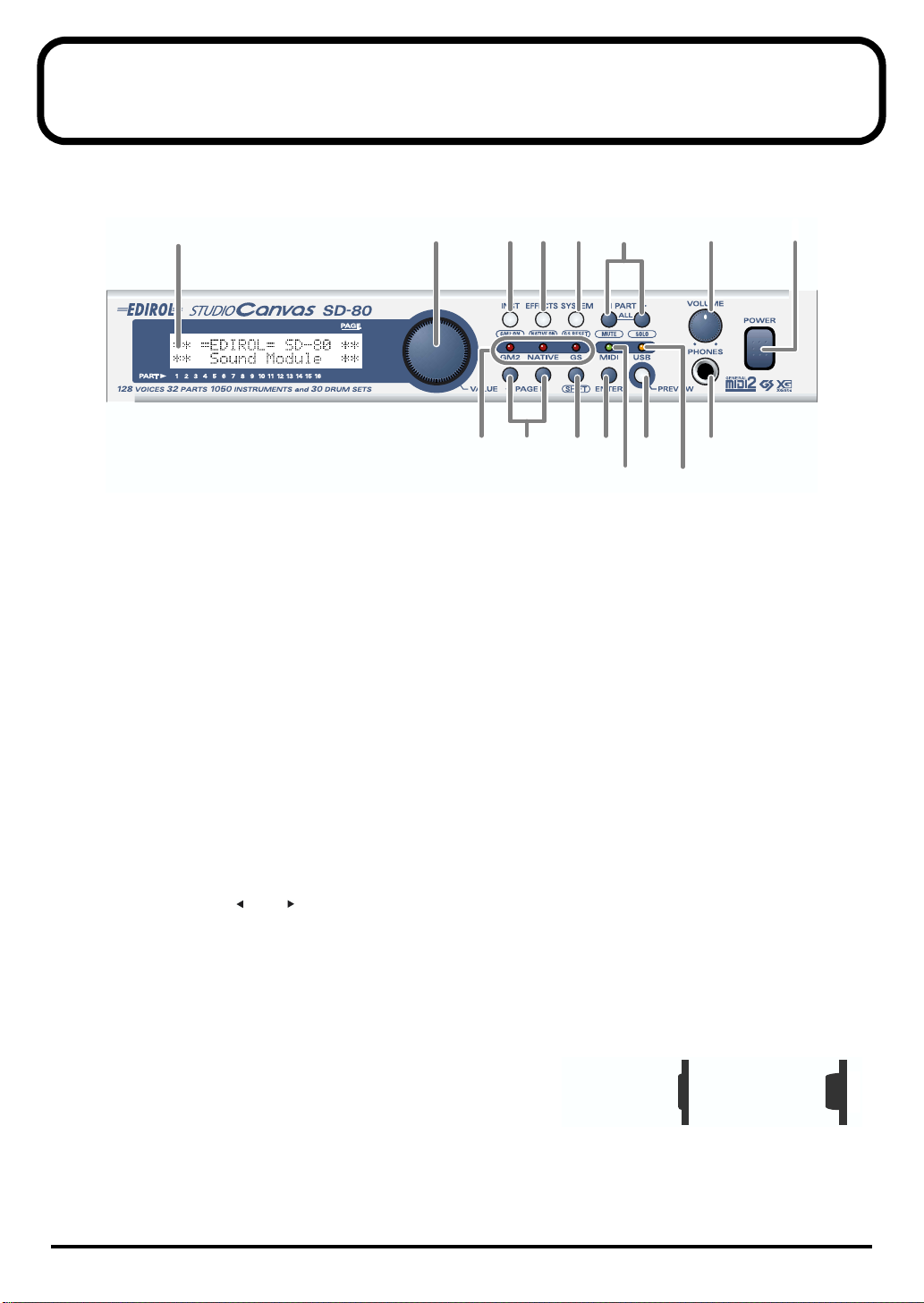
Names of things and what they do
■
Front Panel
fig.1-01
1
2 3 546 7
8
9
10
12
1411
16
13 15
1
Display
This shows various types of information (such as level meters or parameter values) related to the current
state.
2
VALUE dial
Turn this dial to change a parameter’s setting, or “value.” If you hold down [SHIFT] as you turn
[VALUE], the parameter’s value will change by larger increments.
3
INST (Instrument) Button
Use this button to select the instrument (sound) or drum set assigned to each part. (
(p. 26),
"Selecting a drum set"
4
EFFECTS Button
Use this button to select an effect (MFX) for the internal sound generator, or to edit effect parameters
(
"About the sound generator effects"
5
SYSTEM Button
Use this button to make settings that affect the entire SD-80 system (
6
PART Buttons
Use these buttons to switch the part display.
If you press [] and [] simultaneously, all parameters will be displayed (
common to all parts"
7
VOLUME Knob
This knob adjusts the output level of the audio signal that is output from the rear panel
and from the
fig.1-01a
8
POWER Switch
This turns the power of the SD-80 on/off. The
when the switch is pressed in, and the
switch is in the outward position. When the power is on, the
white backlighting of the LCD screen will also be on.
headphone jack
(p. 32)).
(p. 27))
.
(p. 39)).
power is on
power is off
when the
"System-related settings"
"Editing parameters that are
Pressed in
ON
"Selecting a sound"
OUTPUT 1
Outward position
OFF
(p. 49)).
jacks
10

Names of things and what they do
9
Mode Indicators
This indicates the sound generator mode in which the SD-80 is operating. The indicator of the current
sound generator mode will light red.
In the case of XGlite mode, all the
10
PAGE Buttons
Use these buttons to switch between screens that consist of multiple pages (
(p. 31)).
11
SHIFT Button
This button is used in conjunction with other buttons to change the function of the other button.
12
ENTER Button
Use this button to execute an operation or to select a screen.
13
MIDI Indicator
This will light when the SD-80 is operating in MIDI mode. (
14
PREVIEW Button
Use this button to audition the currently selected sound (instrument) (
(Preview)"
15
USB Indicator
This will light when the SD-80 is operating in USB mode. (
When you connect the SD-80 to your computer via a USB cable, the SD-80 will automatically switch to
USB mode
automatically switch to
16
Headphone Jack
A set of headphones can be connected to this jack. The headphone jack outputs the same signal as the
OUTPUT 1
(p. 14).
. If your computer is not powered-on, or if the USB cable is disconnected, the SD-80 will
MIDI mode
jacks.
mode indicators
.
will be dark.
"MIDI mode"
"USB mode"
"Editing part parameters"
(p. 20))
"Auditioning the sounds
(p. 19))
Names of things
11
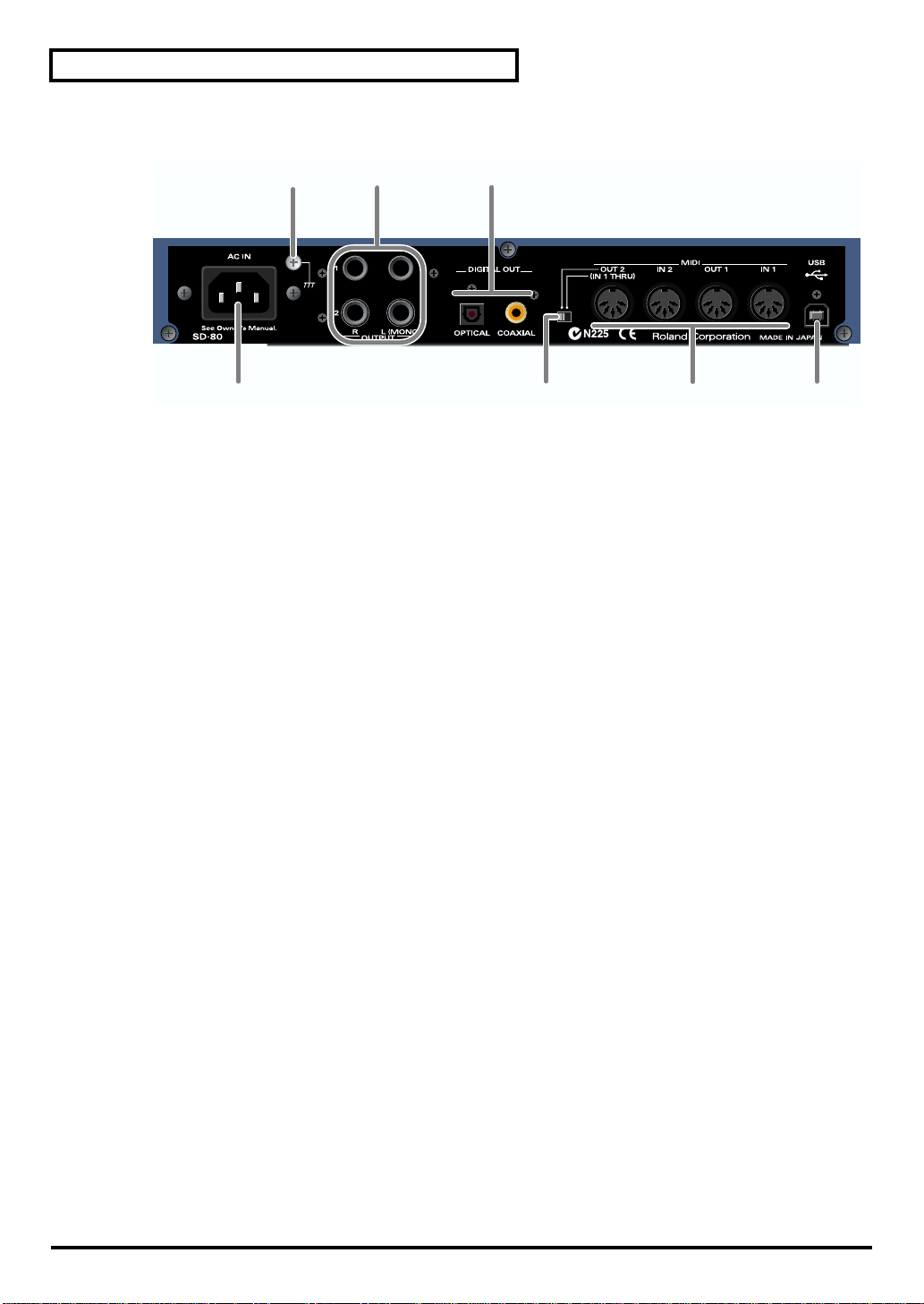
Names of things and what they do
■
Rear Panel
fig.1-02
18
19
20
17
17
AC IN Connector
Connect the supplied AC cable here. Never use any AC cable other than the one provided, since doing so
may cause malfunction.
18
Grounding Terminal
In some cases, depending on the environment in which the unit is installed, the surface of the panel may
sometimes feel rough and grainy. This is due to an infinitesimal electrical charge, which is absolutely
harmless. However, if you are concerned about this, connect the ground terminal (see figure) with an
external ground. When the unit is grounded, a slight hum may occur, depending on the particulars of
your installation. If you are unsure of the connection method, contact the nearest Roland Service Center,
or an authorized Roland distributor, as listed on the “Information” page.
●
Unsuitable places for connection
• Water pipes (may result in shock or electrocution)
• Gas pipes (may result in fire or explosion)
• Telephone-line ground or lightning rod (may be dangerous in the event of lightning)
19
OUTPUT Jacks
These jacks output audio signals to your audio playback system or amplified speakers.
The output destination setting of a part will determine whether its sound is sent to
Normally, the sound will be sent to the
The front panel
20
DIGITAL OUT Jacks
These jacks can be connected to digital audio devices such as CD players and MD players to transfer
digital audio signals.
Use a coaxial cable for
* The digital output transmits the OUTPUT 1 signal.
* The signal that is sent from the SD-80's DIGITAL OUT jack may be digitally copied for one or more generations.
21 MIDI OUT/THRU Switch
If this is set to [IN1 THRU], the MIDI messages sent to the MIDI IN 1 connector will be retransmitted
without change from the MIDI OUT 2 connector.
22 MIDI Connectors
These connectors can be connected to other MIDI devices, such as a sequencer, allowing the exchange of
MIDI messages ("Controlling the SD-80 via MIDI" (p. 53)).
IN1/IN2: These connectors receive MIDI messages from other devices. The received MIDI
OUT1/OUT2: These connectors transmit MIDI messages to other devices.
23 USB Connector
A USB cable can be used to connect the SD-80 to your computer.
VOLUME knob
COAXIAL
messages are sent to the computer (in USB mode) or to the internal sound generator (in
MIDI mode).
OUTPUT 1
affects only the
, and an optical digital cable for OPTICAL.
jacks.
OUTPUT 1
jacks.
22
OUTPUT
jacks 1 or 2.
2321
12
Basic operation
Operations in the basic screen
The SD-80 contains a diverse array of sounds, ranging from instrumental sounds such as piano/organ/
guitar for an ensemble, to sound effects such as birdsong and telephone ringers. Each of these sounds is
called an instrument. Here’s how to select instruments and listen to the variety of sounds that the SD-80
provides.
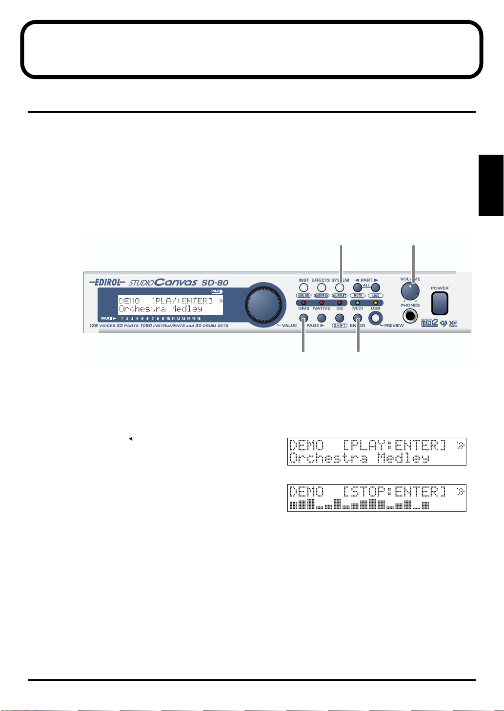
■ Listening to the internal demo songs
The SD-80 contains demo songs. Here’s how to listen to these demo songs, and hear the sounds and
effects.
fig.2-05
2,6
Basic operation
1
3
1. Turn the [VOLUME] knob fully counterclockwise (minimum setting).
2. Press [SYSTEM].
The button will light.
fig.2-05a
3. Press [PAGE ] to get the screen shown at right to
appear.
4. Turn the [VALUE] dial to select a demo song.
fig.2-05b
5. Press [ENTER], and the demo song will begin playing.
Slowly turn the [VOLUME] knob clockwise to adjust the
volume to a comfortable level. Once the demo song has
played to the end, it will automatically be played over
again, starting from the beginning.
6. Press [ENTER] once again to stop the demo song.
At this time you will automatically return to the beginning of the song.
7. Press [INST] to return to the main screen.
* Use of the song data supplied with this product for any purpose other than private, personal enjoyment without the
permission of the copyright holder is prohibited by law. Additionally, this data must not be copied, nor used in a
secondary copyrighted work without the permission of the copyright holder.
* No data for the music that is played will be output from MIDI OUT.
4,5
13
Basic operation
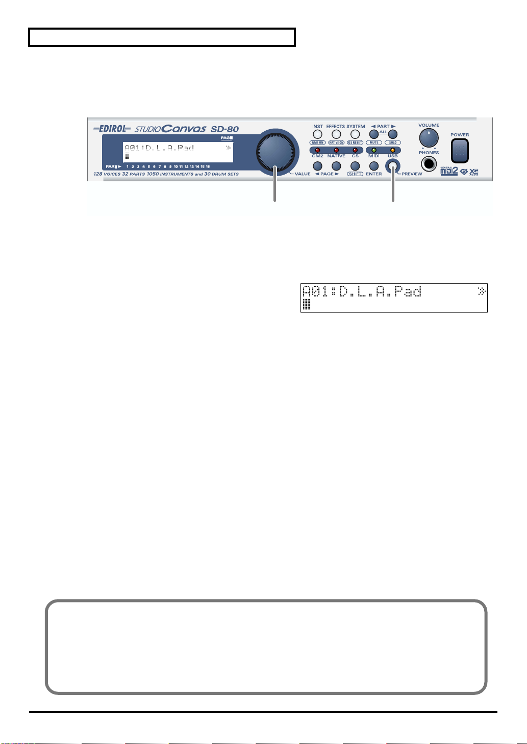
■ Auditioning the sounds (Preview)
On the SD-80, sounds are specified using two numbers: the instrument number and the variation
number. By pressing [PREVIEW] you can audition the currently selected sound.
fig.2-03a
2
1. Press [PREVIEW]. While you continue pressing [PREVIEW], the button will light and a phrase will play.
When you release the button, the phrase will stop.
If you press the [PREVIEW] key and release it immediately, the phrase will play back to the end. In this
case, you can stop the phrase playback by pressing [PREVIEW] once again.
2. Turn the [VALUE] dial to switch sounds.
At start-up, the native mode sounds will be selected.
1
14
Changing the Preview settings
At the factory settings, you can audition a characteristic phrase that uses the currently selected sound
(Phrase Preview). Alternatively, you can set it so that Preview will play a single note at the pitch (key)
and strength (velocity) that you specify.
For details on Preview settings, refer to "Preview settings" (p. 52).
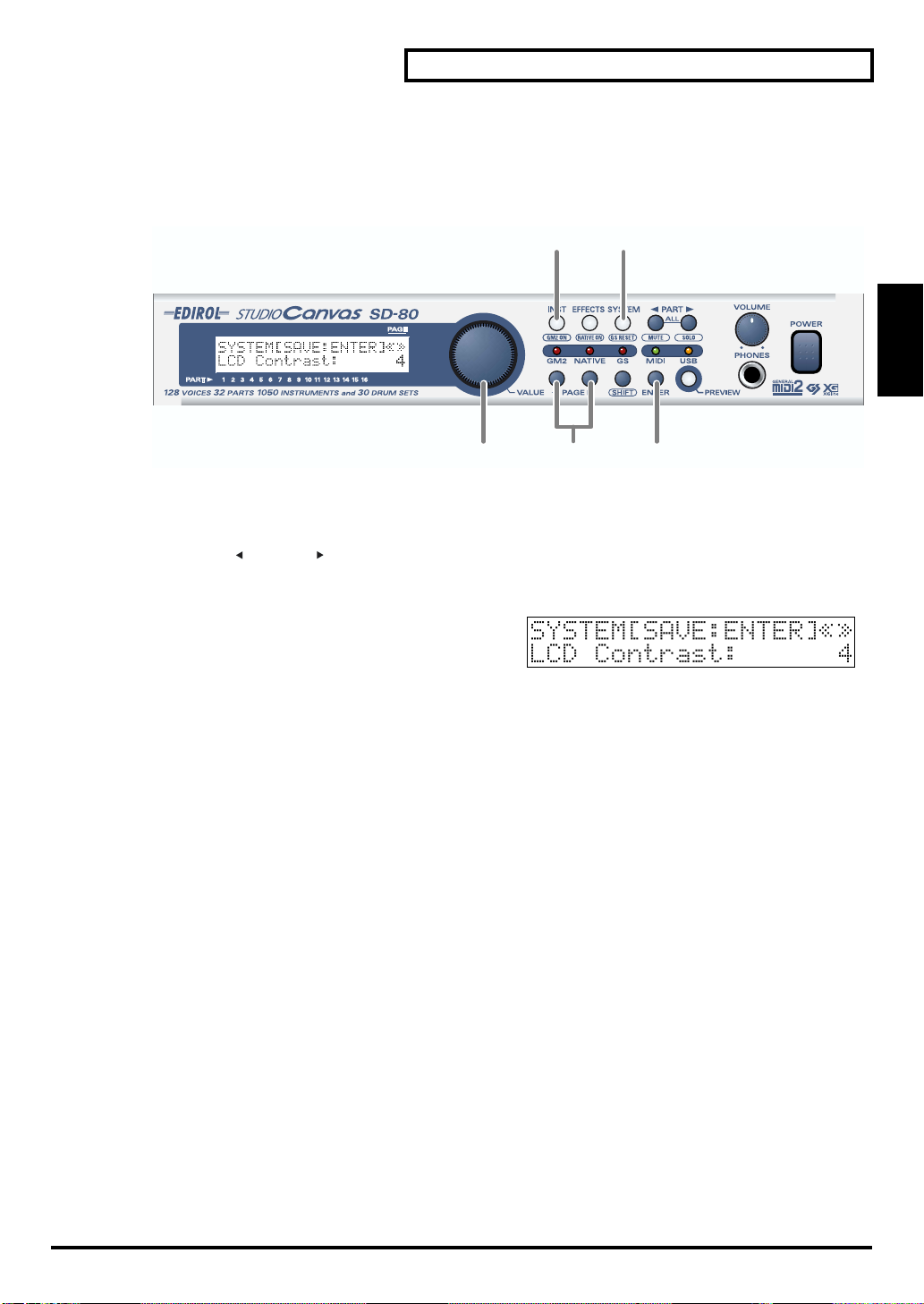
■ Adjusting the brightness of the display (Contrast)
Immediately after the power is turned on, or after the SD-80 has been used for an extended period, or
depending on the conditions in which it is placed, the characters or icons in the display screen may
become difficult to read. If this happens, you can adjust the contrast of the display.
fig.2-02
5
1
Basic operation
Basic operation
3
1. Press [SYSTEM].
The button will light.
2. Press [PAGE ] or [PAGE ] until LCD Contrast is displayed.
3. Turn the [VALUE] dial to adjust the contrast of the display.
fig.2-03
LCD Contrast 1–4–5
Adjusts the contrast of the display.
4. Press [ENTER]. The contrast setting you specify will be remembered by the SD-80.
* Do not turn off the power while the setting is being stored (while “(TBD)” is displayed). Doing so will cause all data
stored in the SD-80 to be lost.
5. Press [INST] to return to the main screen.
2
4
15
Using the internal sound generator
The SD-80 contains a sound generator with 1,050 diverse and high-quality sounds. The internal sound
generator has four modes to support different sound generator formats, and you can select the mode you
want to use. For details on the sound generator modes, refer to "About the sound generator modes" (p.
16).
Multi-effect, chorus, reverb, and equalizer (a total of four effects units) are also built-in, letting you
apply effects to the internal sound generator. For details on the effects, refer to "Using the effects of the
internal sound generator" (p. 39).
About the sound generator modes
The SD-80 has four sound generator modes: GM2, Native, GS, and XGlite.
GM2 mode further consists of four sound sets, and Native mode consists of six sound sets. For details on
the sound sets, refer to "GM2/Native mode sound sets" (p. 17).
With the factory settings, the SD-80 is set to start up in Native mode.
GM2 mode
This sound generator mode is compatible with the “GM2” sound generator format.
GM2 is “recommended practice,” and it is backwardly compatible with GM. It was created in order to
allow more sophisticated performance expression and greater compatibility. It includes detailed
definitions concerning sound editing and the use of effects (things that weren’t covered by the earlier GM
format), and it also expands the sound set. GM2-compatible sound generators will correctly play back
music data bearing either the GM or GM2 logos.
When it is necessary to make a distinction, this manual will sometimes refer to “GM1” to indicate the
earlier GM format which does not include the extended specifications of GM2.
Native mode
This is the sound generator mode that allows you to take advantage of the SD-80’s full potential.
It uses the same instrument files and sound sets as GM2 mode, and provides a greater number of editable
parameters.
In addition, it provides two special sound sets that collect the most distinctive of the sounds of the SD-80.
GS mode
This sound generator mode supports the “GS” sound generator format promoted by Roland Corporation.
In addition to the General MIDI functionality, this format expands the sound set, and also enhances
compatibility by providing detailed specifications for functionality such as sound editing and effects
(reverb and chorus). For flexibility in meeting future needs, it also provides for the addition of new
sounds and expanded functionality. Since the GS format is compatible with GM, it allows GM scores to be
played in the same way as GS music data (music data created in conformity with the GS format).
* It is not possible to edit GS mode sound generator parameters from the panel of the SD-80.
XGlite mode
XG is a sound generator format promoted by Yamaha Corporation, which is based on GM1 (General
MIDI 1). It provides detailed specifications concerning expansion of the sound sets, editing methods, and
effects structures and types.
XGlite is a reduced-functionality (“lite”) version of XG, which allows simple playback of XG music data
on a sound generator bearing the XGlite logo. Since XGlite has some limitations on the parameters and
effects that can be controlled, the XG music data may sound different than the original data.
* It is not possible to edit XGlite mode sound generator parameters from the panel of the SD-80.
16

About GM2/Native modes
■ GM2/Native mode sound sets
The sounds sets of GM2 mode and Native mode are organized by their character into four or six
variations.
fig.5-01
Classical
This is the basic sound set that blends well into an ensemble. This set is
also used when GM2 data compatibility is important.
Contemporary
This sound set emphasizes the realism of each individual instrument. It
contains numerous sounds that use velocity switching for expressive
dynamics.
Solo
This sound set contains mainly sounds that are designed to be
distinctive when used to play solos. These sounds include spacious
stereo-sampled sounds, as well as sounds that are switched by velocity.
Using the internal sound generator
SD-80
GM2
Classical
Contemporary
Solo
Enhanced
GS
Native
Classical
Contemporary
Solo
Enhanced
Special 1
Special 2
XGlite
Using the internal
sound generator
Enhanced
This sound set concentrates on sounds that are designed with multi-effects (MFX), such as distortion
guitar and rotary organ. You can obtain an effect simply by selecting one of these sounds. The set also
includes acoustic instruments with a clear upper register produced by equalization processing, and synth
sounds based on multi-effects.
Up to three enhanced sounds can be used simultaneously. This set also contains some sounds that do not
use MFX.
* With the factory settings in Native mode, parts 1--3 allow you to use special sounds or enhanced sounds that use
MFX.
Special
This sound set can be used only in Native mode. It consists mainly of the best sounds of the SD-80 from
the Enhanced set, and also includes highly original sounds not defined by GM2.
As with the Enhanced set, most sounds use multi-effects (MFX).
Parameters that can be used in GM2 mode
fig.5-01a
In GM2 mode it is not possible to edit
the sounds themselves.
Multi-effects (MFX) and the sounds
are always handled as a unit, and are
always included in the Enhanced
sound set. (In the example shown in
the diagram at right, an Enhanced
sound is selected for Part 2.)
Part 1
Part 2
Part 32
Sounds
Sounds
Sounds
MFX
Part
Parameters
Part
Parameters
Part
Parameters
17
Using the internal sound generator
About parts and sounds
The SD-80 is able to produce 32 different sounds at once. A sound generator such as the SD-80 that is able
to produce many different sounds simultaneously is called a “multitimbral sound module.” “Timbre”
refers to the unique characteristics that result in the sound of one instrument being different from that of
another. The ability to simultaneously produce 32 different instrument sounds means that, using the
analogy of an orchestra, you can produce an ensemble consisting of 32 different instrumental parts. On
the SD-80, the sound produced by each part is called an Instrument ("Instrument list (GM2 / Native
mode)" (p. 95)). You can assign a desired instrument to each of the 32 parts, creating a 32-part ensemble.
■ Different types of part
The SD-80 has 32 parts, which are divided into groups A and B. Each group is numbered from 01–16; i.e.,
A01–A16 and B01–B16.
Each part can be set either as an Inst part or a Drum part. Inst parts are used to play melody, bass, etc.
Drum parts are used to play percussion-type sounds. This setting is called the Part Mode.
By default, the following part mode is selected for each part.
Part mode Corresponding parts
Inst part A01–09, A11–16, B01–09, B11–16
Drum part A10, B10
■ Polyphony and voices
Each of the SD-80’s sounds consist of units called “voices.” There is a limit to the number of voices that
can be used, and the SD-80 is able to use 128 voices simultaneously. Some sounds (instruments) use
more than one voice ("Instrument list (GM2 / Native mode)" (p. 95)). The main reason that an instrument
uses some voices is so that velocity can be used to shift between different sounds, or so that multiple
sounds can be layered to create a richer tone.
When you attempt to play more than 128 voices on the SD-80, the most-recently played note will be given
priority, and the oldest of the currently-sounding notes will be turned off one by one. If you are using
only instruments that consist of only one voice, you will be able to play 128 notes simultaneously.
However, if you use instruments that consist of two or four voices, fewer than 128 notes can be played
simultaneously. Even if a MIDI note-off message is received, a voice will continue to be used as long as
that note continues to sound. You need to remain aware of this, particularly when using sounds that have
a long release time.
18
Using the internal sound generator
Specifying the function of the MIDI connectors
The SD-80 has two modes in which MIDI data is transferred differently: USB mode and MIDI mode.
The mode is switched automatically depending on the connector you use.
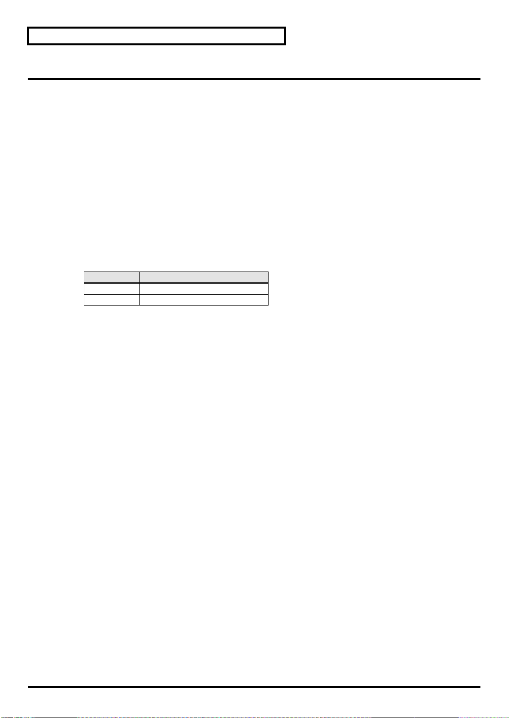
■ USB mode
fig.7-2
MIDI messages received at the MIDI IN connectors
will not be passed directly to the internal sound
generator. They will be sent via USB to the computer
(sequencer software).
This means that if you have started up in USB
mode, playing an external MIDI keyboard
connected to a MIDI IN connector will not play the
SD-80’s internal sound generator. In order for the
MIDI messages received at the MIDI IN connectors
to be passed to the internal sound generator, you
must turn on the Thru function of your software
running on your USB-connected computer. “Thru”
is a function by which MIDI messages received from
the SD-80’s USB connector are retransmitted back to
the SD-80’s USB connector. If the Thru function is
turned on, the MIDI messages received at the MIDI
IN connectors will pass through the computer and
be passed to the SD-80’s internal sound generator,
causing sound to be produced.
* The number of internal sound generator parts that can be
controlled from the USB connector will depend on the
capabilities of your sequencer software. This means that
even if you connect the SD-80 to your computer via USB,
you will not necessarily be able to use all 32 parts. Please
carefully read the owner’s manual for your sequencer
software.
* The USB indicator will light.
MIDI OUT 1
MIDI OUT 2
MIDI IN 1
MIDI IN 2
THRU function : ON
USB
Part A1 - A16
Part B1 - B16
Part group A
Part group B
SD-80
Using the internal
sound generator
19

Using the internal sound generator
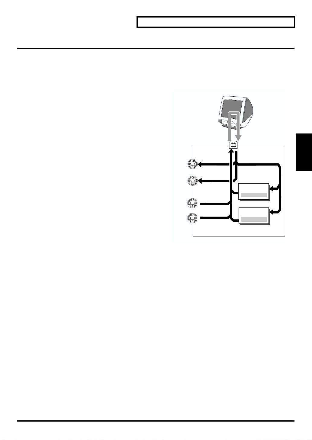
■ MIDI mode
fig.7-3
The MIDI messages received at the MIDI IN
connectors will be passed directly to the internal
sound generator.
The SD-80 has two MIDI IN connectors, and each
MIDI IN connector can receive data for 16 Parts. In
MIDI mode, when you play using the MIDI
connectors, group A corresponds to the MIDI IN 1
connector and group B corresponds to the MIDI IN 2
connector. In other words, the MIDI messages
received at MIDI IN 1 will play Parts 01–16 of group
A, and the MIDI messages received at MIDI IN 2 will
play Parts 01–16 of group B. For example, a MIDI
message received at MIDI IN 1 on channel 5 will play
Group A Part 5 (A05) (when still set to the default
settings).
* If you want to change the correspondence of Parts to MIDI
channels, you can send the System Exclusive message
Rx.CHANNEL via MIDI.
* The MIDI indicator will light.
* If you want to use the SD-80 in MIDI mode, disconnect the
USB cable from the SD-80's USB connector.
MIDI
interface
MIDI OUT 1
MIDI OUT 2
MIDI IN 1
MIDI IN 2
Part group A
Part
A1 - A16
Part group B
Part
B1 - B16
USB
SD-80
20
Using the internal sound generator
Specifying the function of the MIDI connectors
If the MIDI OUT/THRU switch on the rear panel is set to [IN1 THRU], MIDI messages received at the MIDI
IN 1 connector will be retransmitted without change from the MIDI OUT 2 connector.
If the SD-80 is operating in USB mode and this switch is set to [IN1 THRU], MIDI messages received at
the MIDI IN 1 connector will be "thru-ed" from the MIDI OUT 2 connector. The MIDI messages that would
normally be output from the computer to the MIDI OUT 1 connector will no longer be output. (They will
not be merged.) In this case, it will not be possible to use USB external output 2 (EDIROL SD-80 MIDI
OUT 2) from the computer.
However, if the SD-80 is operating in MIDI mode and this switch is set to [IN1 THRU], MIDI messages
received at the MIDI IN 1 connector will be "thru-ed" from the MIDI OUT 1 connector as well as being sent
to PART A. In this case, if an external MIDI device sends a dump request to PART B, it will not be
possible to transmit the response.
fig.7-4a
USB mode
THRU function : ON
MIDI
interface
MIDI mode
THRU function : ON
Using the internal
sound generator
MIDI OUT 1
MIDI OUT 2
MIDI IN 1
MIDI IN 2
USB
Part group A
Part A1 - A16
Part group B
Part B1 - B16
SD-80
MIDI OUT 1
MIDI OUT 2
MIDI IN 1
MIDI IN 2
USB
Part group A
Part A1 - A16
Part group B
Part B1 - B16
SD-80
21

Using the internal sound generator
1
1
2
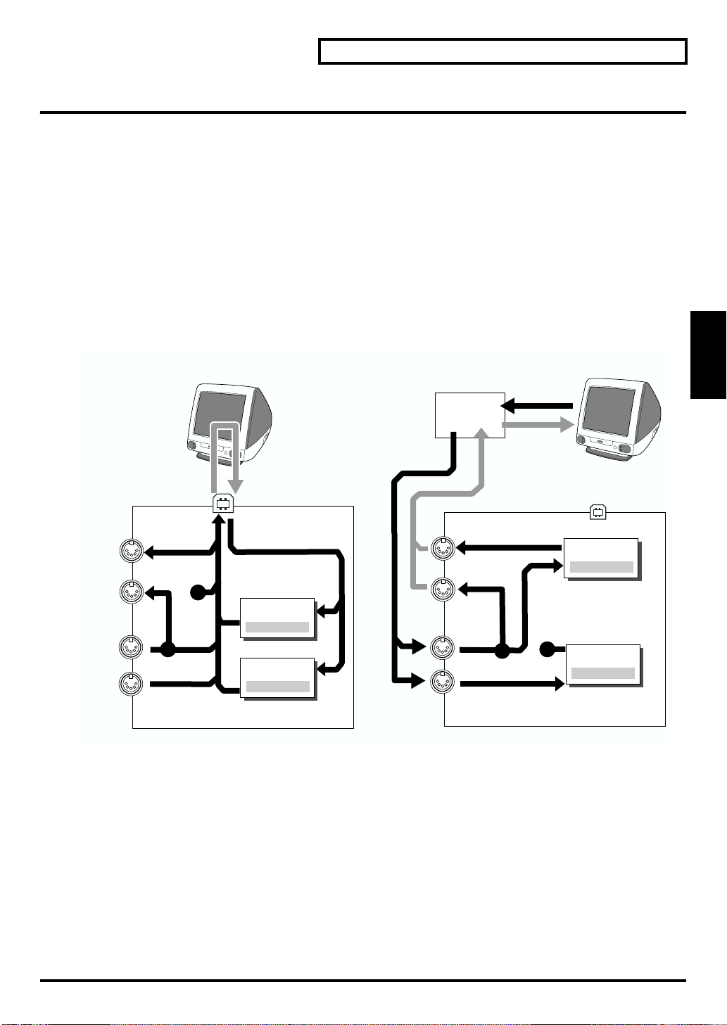
Switching the sound generator mode
Here’s how to switch the sound generator mode. The sound generator mode can be switched from the
front panel, or by MIDI messages from an external device. Please be aware that the sound generator will
be initialized when you switch the sound generator mode.
fig.5-02
5
1
3
1. Press [SYSTEM].
The button will light.
fig.7-01a_67.2
2. Press [PAGE ] or [PAGE ] until you have Inst Init
showing in the display.
3. Turn the [VALUE] dial to select the desired sound generator mode (GM2, Native, GS, XGlite).
fig.5-02a
4. Press [ENTER]. You will switch to the sound generator mode you selected in step 3.
The front panel mode indicators show the current sound generator mode.
5. Press [INST] to return to the main screen.
2
4
Convenient functions
You can use the following shortcuts to switch the sound generator mode.
fig.5-01a
1. Hold down [SHIFT] and press the button for the desired sound generator
mode.
[INST] ............. GM2 ON (GM2 mode)
[EFFECTS] ..... NATIVE ON (Native mode)
[SYSTEM]....... GS RESET (GS mode)
2. The front panel mode indicators show the current sound generator mode.
22
Selecting a part
Here’s how to select the part that you want to edit.
fig.5-03
1. Press [INST].
The button will light.
fig.5-03a_67.2
2. Press [PART ] or [PART ] to select the part to be
edited. The number of the part currently being edited is
indicated at the bottom of the display.
Using the internal sound generator
1
2
Using the internal
sound generator
23
Using the internal sound generator
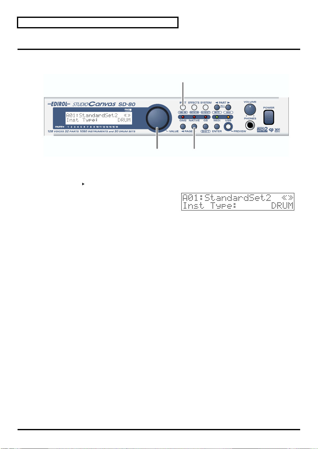
Selecting the type of part (INST/DRUM)
Here’s how to select the type (Part Mode) for each part.
* Inst Type can be executed only if the sound generator mode is GM2 mode or Native mode.
fig.5-04
1,4
23
1. Press [INST].
The button will light.
2. Press [PAGE ] until the display indicates Inst Type.
3. Turn the [VALUE] dial to select the desired part mode
(INST or DRUM).
The part mode has now been selected.
4. Press [INST] once again to return to the basic screen.
24
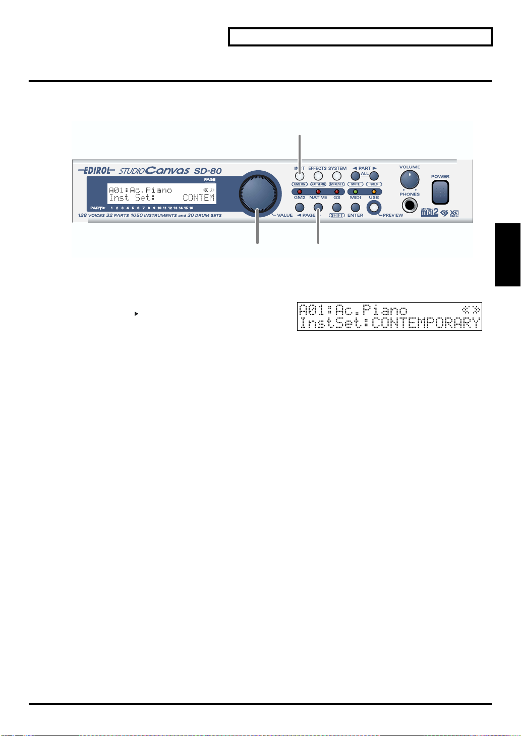
Selecting the sound set
In GM2 mode you can choose one of four different sound sets. In Native mode you can choose one of six
different sound sets.
fig.5-05
1. Press [INST].
The button will light.
fig.5-05a_67.2
2. Press [PAGE ] until the display indicates Inst Type.
1,4
Using the internal sound generator
Using the internal
sound generator
23
3. Turn the [VALUE] dial to select the desired sound set.
CLASSICAL: Classical
CONTEMPORARY: Contemporary
SOLO: Solo
ENHANCED: Enhanced
SPECIAL 1: Special 1 (Native mode only)
SPECIAL 2: Special 2 (Native mode only)
USER: User (Native mode only)
The sound set has now been selected.
4. Press [INST] once again to return to the main screen.
25

Using the internal sound generator
Selecting a sound
If the part type is Inst, use the following procedure to select a sound. First make sure that the part type is
Inst. For details on how to set the part type to Inst, refer to "Selecting the type of part (INST/DRUM)" (p.
24).
On the SD-80, the sound of an Inst part is specified by two numbers: an Instrument number and a
Variation number. There are 128 sounds whose variation number is 000, and these make up the basic
sounds of the SD-80. These are referred to as “capital sounds.”
By changing the MIDI bank number of these sounds, you can select variations that have a different tonal
character. These are called “variation sounds.” For details on the various sounds that can be selected,
refer to "Instrument list (GM2 / Native mode)" (p. 95).
fig.5-06
1,6
2,43,5
1. Press [INST].
The button will light.
fig.5-06a_67.2
2. Press [PAGE ] until the display indicates Inst
Number.
3. Turn the [VALUE] dial to select a capital sound.
The sound name and Inst Number shown in the display will also change.
4. Press [PAGE ] until Variation appears.
In GS mode, this will be displayed with Bank.
5. Turn the [VALUE] dial to select a variation sound.
The sound name and Inst Number shown in the display will also change.
6. Press [INST] once again to return to the main screen.
Convenient functions
You can also use the following method to select a sound.
After step 1, if you turn the [VALUE] dial, any sound in the current sound set can be selected.
26
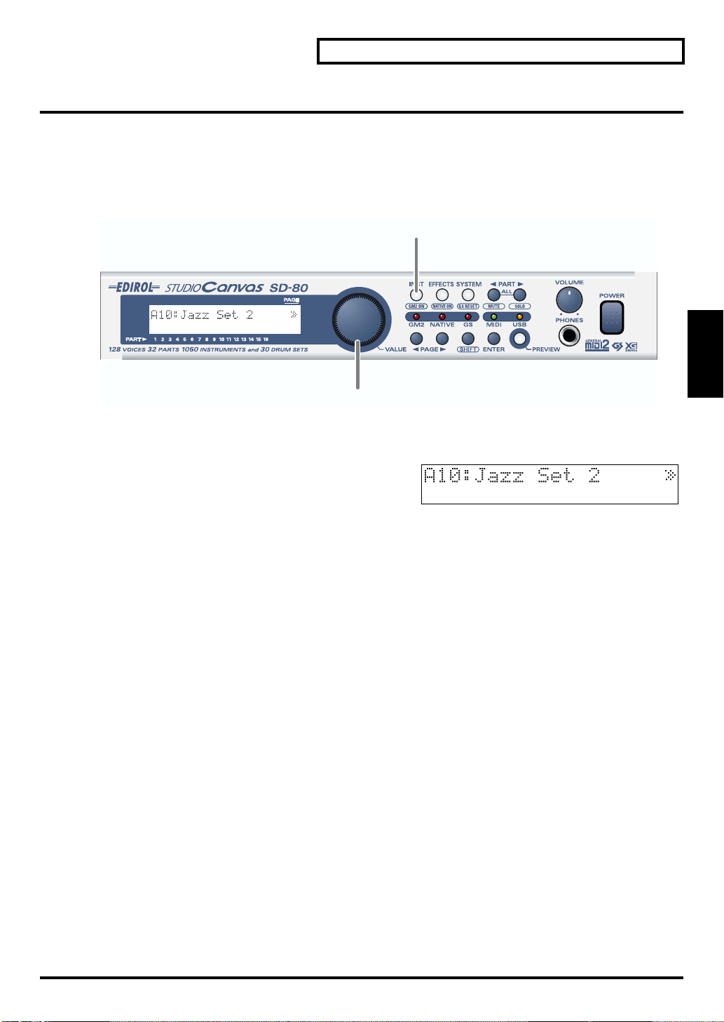
Selecting a drum set
If the part type is Drum Set, use the following procedure to select a drum set. First make sure that the part
type is Drum. For details on how to set the part type to Drum, refer to "Selecting the type of part (INST/
DRUM)" (p. 24).
For details on the drum sets that are available, refer to "Instrument list (GM2 / Native mode)" (p. 95).
* Drum sets do not have variation sounds.
fig.5-07
1. Press [INST].
The button will light.
fig.5-07a_67.2
2. Turn the [VALUE] dial to select a drum set. The drum
set name shown in the display will change.
Using the internal sound generator
1
Using the internal
sound generator
2
27
Using the internal sound generator
Muting/soloing a part
You can “mute” a specified part so that it will not sound. This is convenient when you want to play along
to a backing provided by the SD-80 (“minus-one” playing).
Conversely, you can “solo” a specified part so that the remaining parts will be muted.
Here’s how to mute/solo a part.
* Solo takes priority between solo and mute settings. This means that if you specify Solo for a part that was previously
muted, Mute will be defeated for that part, and it will be set to Solo. Even if you subsequently cancel Solo, that part
will not return to Mute. If you want to mute that part once again, use the procedure described in “Muting a part.”
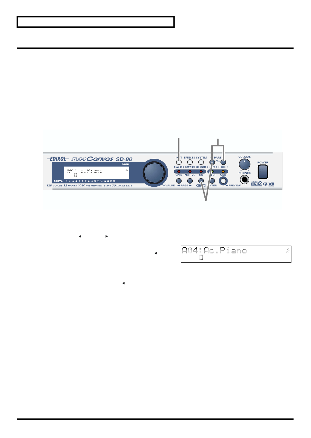
■ Muting a part
fig.5-08
1,4
2
1. Press [INST].
The button will light.
2. Press [PART ] or [PART ] to select the part that you want to mute.
fig.5-08a_67.2
3. When you hold down [SHIFT] and press [PART ], the
part you selected in step 2 will be muted. The bar graph
of a muted part will be displayed as shown in the
diagram at right.
When you press [SHIFT]+[PART ] once again, muting will be defeated.
3
28

■ Soloing a part
When multiple parts are sounding, you can cause only the currently selected part to sound, allowing you
to check the performance of that part. This is referred to as “soloing” the part.
fig.5-09
1. Press [INST].
The button will light.
2. Press [PART ] or [PART ] to select the part that you want to solo.
fig.5-09a
1,4
Using the internal sound generator
2
Using the internal
sound generator
3
3. Hold down [SHIFT] and press [PART ] to solo the part
you selected in step 2. Parts other than the soloed part
will not sound, nor will the bar graph be displayed.
Solo will be defeated when you press [SHIFT]+[PART ] once again.
29
Using the internal sound generator
About parameters
This section explains the parameters (items that you can set). Parameters are settings that determine how
a sound is produced, and the process of modifying the values of the parameters is called “editing.”
If you are using the SD-80 in GM2 mode or Native mode, some of the Part parameter values can be
edited from the panel of the SD-80 itself. In other modes, parameter values cannot be edited from the
panel of the SD-80. However, the parameters can be edited by using the editing functionality of your
computer software or sequencer.
For details on how to edit the parameters, refer to the “MIDI Implementation” (MIDIImp_E.pdf) on the
included CD-ROM. The adjustable range of each parameter is printed in this manual as described in the
comment column of the MIDI implementation.
30
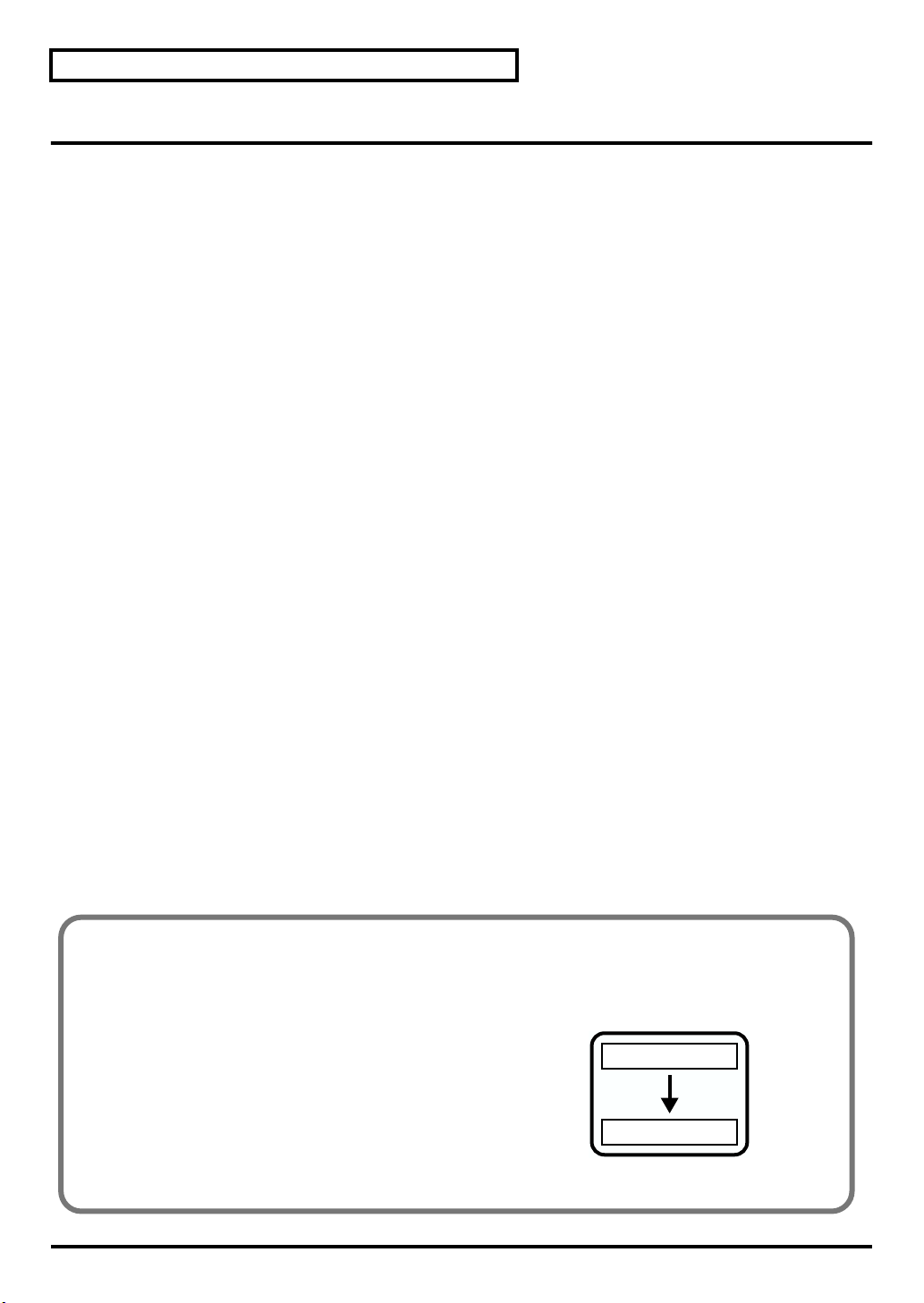
Internal operation of parameters
When you select a sound, the sound data is loaded into a memory location called the “temporary area.”
The SD-80 produces sound based on the data in this temporary area.
fig.5-14
When you edit a sound or drum set, you are temporarily
modifying the settings of the data in the temporary area. It is
not possible for the edited sounds to be saved in the
internal memory of the SD-80. Your edits will be lost when
you turn off the power. If you want to preserve the edited
state, you can either make a note of the settings, or save
them on an external MIDI device, such as a MIDI sequencer
("Writing/loading SD-80 settings" (p. 69)).
Internal sounds
Called up
Temporary area
 Loading...