

Owner’s Manual
Bedienungsanleitung
Mode d’emploi
Manuale d’uso
Manual del usuario
Thank you, and congratulations on your choice of the SD-20.
Before using this unit, carefully read the sections entitled: “USING THE UNIT
SAFELY” and “IMPORTANT NOTES” (Owner’s manual pp. 3--5). These
sections provide important information concerning the proper operation of the
unit. Additionally, in order to feel assured that you have gained a good grasp
of every feature provided by your new unit, Owner’s manualshould be read in
its entirety. The manual should be saved and kept on hand as a convenient
reference.
Copyright © 2002 ROLAND CORPORATION
All rights reserved. No part of this publication may be reproduced in any form without
the written permission of ROLAND CORPORATION.
For the U.K.
IMPORTANT: THE WIRES IN THIS MAINS LEAD ARE COLOURED IN ACCORDANCE WITH THE FOLLOWING CODE.
BLUE:
BROWN:
As the colours of the wires in the mains lead of this apparatus may not correspond with the coloured markings identifying
the terminals in your plug, proceed as follows:
The wire which is coloured BLUE must be connected to the terminal which is marked with the letter N or coloured BLACK.
The wire which is coloured BROWN must be connected to the terminal which is marked with the letter L or coloured RED.
Under no circumstances must either of the above wires be connected to the earth terminal of a three pin plug.
This product complies with the requirements of European Directive 89/336/EEC.
NEUTRAL
LIVE
For EU Countries
For the USA
FEDERAL COMMUNICATIONS COMMISSION
RADIO FREQUENCY INTERFERENCE STATEMENT
This equipment has been tested and found to comply with the limits for a Class B digital device, pursuant to Part 15 of the
FCC Rules. These limits are designed to provide reasonable protection against harmful interference in a residential
installation. This equipment generates, uses, and can radiate radio frequency energy and, if not installed and used in
accordance with the instructions, may cause harmful interference to radio communications. However, there is no guarantee
that interference will not occur in a particular installation. If this equipment does cause harmful interference to radio or
television reception, which can be determined by turning the equipment off and on, the user is encouraged to try to correct the
interference by one or more of the following measures:
– Reorient or relocate the receiving antenna.
– Increase the separation between the equipment and receiver.
– Connect the equipment into an outlet on a circuit different from that to which the receiver is connected.
– Consult the dealer or an experienced radio/TV technician for help.
This device complies with Part 15 of the FCC Rules. Operation is subject to the following two conditions:
(1) This device may not cause harmful interference, and
(2) This device must accept any interference received, including interference that may cause undesired operation.
Tested To Comply With FCC Standards
FOR HOME OR OFFICE USE
Unauthorized changes or modification to this system can void the users authority to operate this equipment.
This equipment requires shielded interface cables in order to meet FCC class B Limit.
For Canada
NOTICE
This Class B digital apparatus meets all requirements of the Canadian Interference-Causing Equipment Regulations.
AVIS
Cet appareil numérique de la classe B respecte toutes les exigences du Règlement sur le matériel brouilleur du Canada.
For the USA
DECLARATION OF CONFORMITY
Compliance Information Statement
Model Name :
Type of Equipment :
Responsible Party :
Address :
Telephone :
SD-20
Sound Module
Edirol Corporation North America
425 Sequoia Drive, Suite 114, Bellingham, WA 98226
(360) 594-4276
USING THE UNIT SAFELY
Used for instructions intended to alert
the user to the risk of death or severe
injury should the unit be used
improperly.
Used for instructions intended to alert
the user to the risk of injury or material
damage should the unit be used
improperly.
* Material damage refers to damage or
other adverse effects caused with
respect to the home and all its
furnishings, as well to domestic
animals or pets.
001
• Before using this unit, make sure to read the
instructions below, and the Owner’s Manual.
................................................................................................
002c
• Do not open (or modify in any way) the unit
or its AC adaptor.
................................................................................................
003
• Do not attempt to repair the unit, or replace
parts within it (except when this manual
provides specific instructions directing you
to do so). Refer all servicing to your retailer,
the nearest EDIROL/Roland Service Center,
or an authorized EDIROL/Roland
distributor, as listed on the "Information"
page.
................................................................................................
004
• Never use or store the unit in places that are:
• Subject to temperature extremes (e.g.,
direct sunlight in an enclosed vehicle, near
a heating duct, on top of heat-generating
equipment); or are
• Damp (e.g., baths, washrooms, on wet
floors); or are
• Humid; or are
• Exposed to rain; or are
• Dusty; or are
• Subject to high levels of vibration.
The symbol alerts the user to important instructions
or warnings.The specific meaning of the symbol is
determined by the design contained within the
triangle. In the case of the symbol at left, it is used for
general cautions, warnings, or alerts to danger.
The symbol alerts the user to items that must never
be carried out (are forbidden). The specific thing that
must not be done is indicated by the design contained
within the circle. In the case of the symbol at left, it
means that the unit must never be disassembled.
The ● symbol alerts the user to things that must be
carried out. The specific thing that must be done is
indicated by the design contained within the circle. In
the case of the symbol at left, it means that the powercord plug must be unplugged from the outlet.
008c
• Be sure to use only the AC adaptor supplied
with the unit. Also, make sure the line
voltage at the installation matches the input
voltage specified on the AC adaptor’s body.
Other AC adaptors may use a different
polarity, or be designed for a different
voltage, so their use could result in damage,
malfunction, or electric shock.
................................................................................................
009
• Do not excessively twist or bend the power
cord, nor place heavy objects on it. Doing so
can damage the cord, producing severed
elements and short circuits. Damaged cords
are fire and shock hazards!
................................................................................................
010
• This unit, either alone or in combination with
an amplifier and headphones or speakers,
may be capable of producing sound levels
that could cause permanent hearing loss. Do
not operate for a long period of time at a high
volume level, or at a level that is uncomfortable. If you experience any hearing loss or
ringing in the ears, you should immediately
stop using the unit, and consult an audiologist.
................................................................................................
011
• Do not allow any objects (e.g., flammable
material, coins, pins); or liquids of any kind
(water, soft drinks, etc.) to penetrate the unit.
3
012c
• Immediately turn the power off, remove the
AC adaptor from the outlet, and request
servicing by your retailer, the nearest Roland
Service Center, or an authorized Roland
distributor, as listed on the "Information"
page when:
• The AC adaptor or the power-supply cord
has been damaged; or
• Objects have fallen into, or liquid has been
spilled onto the unit; or
• The unit has been exposed to rain (or
otherwise has become wet); or
• The unit does not appear to operate
normally or exhibits a marked change in
performance.
................................................................................................
012d
• Immediately turn the power off, and request
servicing by your retailer, the nearest Roland
Service Center, or an authorized Roland
distributor, as listed on the "Information"
page when:
• Objects have fallen into, or liquid has been
spilled onto the unit; or
• The unit has been exposed to rain (or
otherwise has become wet); or
• The unit does not appear to operate
normally or exhibits a marked change in
performance.
................................................................................................
013
• In households with small children, an adult
should provide supervision until the child is
capable of following all the rules essential for
the safe operation of the unit.
................................................................................................
014
• Protect the unit from strong impact.
(Do not drop it!)
................................................................................................
015
• Do not force the unit’s power-supply cord to
share an outlet with an unreasonable number
of other devices. Be especially careful when
using extension cords—the total power used
by all devices you have connected to the
extension cord’s outlet must never exceed the
power rating (watts/amperes) for the
extension cord. Excessive loads can cause the
insulation on the cord to heat up and
eventually melt through.
................................................................................................
016
• Before using the unit in a foreign country,
consult with your retailer, the nearest Roland
Service Center, or an authorized Roland
distributor, as listed on the "Information"
page.
023
• DO NOT play a CD-ROM disc on a conventional audio CD player. The resulting sound
may be of a level that could cause permanent
hearing loss. Damage to speakers or other
system components may result.
101b
• The unit and the AC adaptor should be
located so their location or position does not
interfere with their proper ventilation.
................................................................................................
102d
• Always grasp only the plug or the body of
the AC adaptor when plugging into, or
unplugging from, an outlet or this unit.
................................................................................................
103b
• Whenever the unit is to remain unused for an
extended period of time, disconnect the AC
adaptor.
................................................................................................
104
• Try to prevent cords and cables from
becoming entangled. Also, all cords and
cables should be placed so they are out of the
reach of children.
................................................................................................
106
• Never climb on top of, nor place heavy
objects on the unit.
................................................................................................
107d
• Never handle the AC adaptor body, or its
plugs, with wet hands when plugging into,
or unplugging from, an outlet or this unit.
................................................................................................
108b
• Before moving the unit, disconnect the AC
adaptor and all cords coming from external
devices.
................................................................................................
108c
• Disconnect all cords coming from external
devices before moving the unit.
................................................................................................
109b
• Before cleaning the unit, turn off the power
and unplug the AC adaptor from the outlet .
................................................................................................
110b
• Whenever you suspect the possibility of
lightning in your area, disconnect the AC
adaptor from the outlet.
................................................................................................
118
• Should you remove the optical connector
caps, make sure to put them in a safe place
out of children's reach, so there is no chance
of them being swallowed accidentally.
4

IMPORTANT NOTES
291a
In addition to the items listed under “USING THE
UNIT SAFELY” on page **, please read and observe
the following:
Power Supply
301
• Do not use this unit on the same power circuit with
any device that will generate line noise (such as an
electric motor or variable lighting system).
302
• The AC adaptor will begin to generate heat after
long hours of consecutive use. This is normal, and is
not a cause for concern.
307
• Before connecting this unit to other devices, turn off
the power to all units. This will help prevent
malfunctions and/or damage to speakers or other
devices.
Placement
351
• Using the unit near power amplifiers (or other
equipment containing large power transformers)
may induce hum. To alleviate the problem, change
the orientation of this unit; or move it farther away
from the source of interference.
352a
• This device may interfere with radio and television
reception. Do not use this device in the vicinity of
such receivers.
352b
• Noise may be produced if wireless communications
devices, such as cell phones, are operated in the
vicinity of this unit. Such noise could occur when
receiving or initiating a call, or while conversing.
Should you experience such problems, you should
relocate such wireless devices so they are at a greater
distance from this unit, or switch them off.
354a
• Do not expose the unit to direct sunlight, place it
near devices that radiate heat, leave it inside an
enclosed vehicle, or otherwise subject it to temperature extremes. Excessive heat can deform or
discolor the unit.
355
• To avoid possible breakdown, do not use the unit in
a wet area, such as an area exposed to rain or other
moisture.
Maintenance
401a
• For everyday cleaning wipe the unit with a soft, dry
cloth or one that has been slightly dampened with
water. To remove stubborn dirt, use a cloth impregnated with a mild, non-abrasive detergent. Afterwards, be sure to wipe the unit thoroughly with a
soft, dry cloth.
402
• Never use benzine, thinners, alcohol or solvents of
any kind, to avoid the possibility of discoloration
and/or deformation.
Additional Precautions
553
• Use a reasonable amount of care when using the
unit’s buttons, sliders, or other controls; and when
using its jacks and connectors. Rough handling can
lead to malfunctions.
556
• When connecting / disconnecting all cables, grasp
the connector itself—never pull on the cable. This
way you will avoid causing shorts, or damage to the
cable’s internal elements.
558a
• To avoid disturbing your neighbors, try to keep the
unit’s volume at reasonable levels. You may prefer
to use headphones, so you do not need to be
concerned about those around you (especially when
it is late at night).
559a
• When you need to transport the unit, package it in
the box (including padding) that it came in, if
possible. Otherwise, you will need to use equivalent
packaging materials.
562
• Use a cable from Roland to make the connection. If
using some other make of connection cable, please
note the following precautions.
• Some connection cables contain resistors. Do not
use cables that incorporate resistors for
connecting to this unit. The use of such cables can
cause the sound level to be extremely low, or
impossible to hear. For information on cable
specifications, contact the manufacturer of the
cable.
Handling CD-ROMs
801
• Avoid touching or scratching the shiny underside
(encoded surface) of the disc. Damaged or dirty CDROM discs may not be read properly. Keep your
discs clean using a commercially available CD
cleaner.
5

Contents
USING THE UNIT SAFELY.......................................................3
IMPORTANT NOTES................................................................5
Features of the SD-20..............................................................7
Check the contents of the package........................................8
Names of things and what they do.........................................9
Front Panel............................................................................................................................9
Rear Panel ...........................................................................................................................10
Exchanging MIDI data with your computer..................................................................11
Basic connections ...............................................................................................................12
About the sound generator modes......................................13
About parts and sounds....................................................................................................15
Different types of part.......................................................................................................15
Polyphony and voices .......................................................................................................15
Getting connected and installing drivers (Windows).........16
USB connection...................................................................................................................17
Serial connection ................................................................................................................28
Settings and checking........................................................................................................38
Background service
?.............................................................................................................................................40
Checking for sound output...............................................................................................41
Getting connected and installing drivers (Macintosh).......42
USB connection...................................................................................................................43
Serial connection ................................................................................................................50
Troubleshooting.....................................................................57
Problems related to the USB driver.................................................................................57
Problems when using the SD-20......................................................................................62
Deleting the driver.............................................................................................................64
Serial MIDI driver settings ...............................................................................................66
Uninstalling the serial MIDI driver.................................................................................69
6
Features of the SD-20
32-part, 64-voice polyphony
Complete studio module including 32-part MIDI synthesizer and 64-voice polyphony for
computer music, karaoke, huge orchestrations and more….
GM2/GS/XGlite 660 tones, 23 drum sets
The standard GM2/GS/XGlite compatible sound selections provide a variety of music genres such
as classicals, contemporary, pop and beyond… Play the realistic instruments tones from Grand
Pianos, Rippin’ Guitars, Jazzy Sax and ethnic drums!!
Optical Digital Output (S/P DIF)
Optical digital connection allows for exceptional MIDI sound quality output not found on any
sound module in its price range.
USB bus powered, adaptor free
USB connection supplies power as well as data. The convenience of having all the mobile elements
of music production.
Easy connection to computer (Serial / USB)
Legacy compatible with serial computers or simply connect through USB for Mac or PC.
ADD
* XG ( ) and XGlite ( ) are trademarks of YAMAHA Corporation.
203
* GS ( ) is a registered trademark of Roland Corporation.
204
* Microsoft and Windows are registered trademarks of Microsoft Corporation.
206c
* Windows® 98 is known officially as: “Microsoft® Windows® 98 operating system.”
206e
* Screen shots in this documents are reprinted with permission from Microsoft Corporation.
206f
* Windows® 2000 is known officially as: “Microsoft® Windows® 2000 operating system.”
206g
* Windows® Me is known officially as: “Microsoft® Windows® Millennium Edition operating system.”
ADD
* Windows® XP is known officially as: “Microsoft® Windows® XP operating system.”
207
* Apple and Macintosh are registered trademark of Apple Computer, Inc.
209
* MacOS is a trademark of Apple Computer, Inc.
220
* All product names mentioned in this document are trademarks or registered trademarks of their respective owners.
231
* OMS is a registered trademark of Opcode Systems, Inc.
232
* FreeMIDI is a trademark of Mark of the Unicorn, Inc.
7

Check the contents of the package
The following items are included in the SD-20 package. After opening the
package, check to see whether any items are missing. If any items are missing,
please contact the dealer from whom you purchased the SD-20.
* The SD-20 package does not include an external amp or speakers, or headphones.
You will need to provide these separately.
fig.SD-20
❏
SD-20
This is a
with USB audio interface.
It supports
GS format
specification for Roland sound generators), and the
Yamaha Corporation.
❏
AC adaptor
This is the only AC adaptor you should use with the SD-20.
Do not use any AC adaptor other than the supplied one, since doing so may
cause malfunction.
Studio Canvas
General MIDI 2
(the universal
unit
,
XGlite
promoted by
You may want to mark the
relevant check box as you
confirm the presence of
each item.
For details on General
MIDI 2, GS format, and
XGlite, please refer to the
SD-20 owner’s manual.
❏
CD-ROM
This contains drivers used by the SD-20, and demo songs.
On the disc, you'll also find PDF files containing detailed information that
should prove helpful if you intend to make full use of the SD-20's advanced
functionality.
fig.0-6a
DO NOT play a CD-ROM disc on a conventional audio CD player.
The resulting sound may be of a level that could cause permanent
hearing loss. Damage to speakers or other system components may
result.
fig.0-7
❏
USB cable
❏
Conversion cable
Stereo miniature phone type <-> RCA phono type
fig.0-10e_30
Owner’s Manual
This is the manual you are holding. Please read this first.
This manual explains how to install the drivers and make the settings
required in order to use the SD-20. Please read the sections that are relevant
to your system.
Avoid touching or
scratching the shiny
underside (encoded
surface) of the disc.
Damaged or dirty CDROM discs may not be
read properly. Keep your
discs clean using a
commercially available CD
cleaner.
8
Names of things and what they do
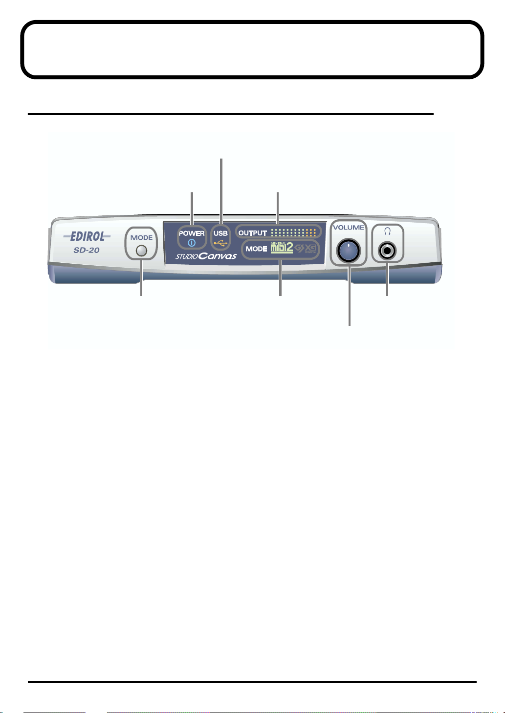
Front Panel
fig.front
USB Indicator
C
POWER Indicator
B
A
MODE Button
A. MODE Button
The sound-module mode changes each time you press this button. (->
modes
(p. 13))
Order of selection
Native mode (at power-up) -> GM2 -> GS -> XGlite
B. POWER Indicator
Lights in blue when the power is on.
OUTPUT Level Indicator
D
E
MODE Indicator
G
Headphone Jack
F
VOLUME Knob
About the sound generator
C. USB Indicator
Lights in orange when data can be transmitted or received via USB.
D. OUTPUT Level Indicator
This will light in four stages to indicate the output level of the sound module.
E. MODE Indicator
This indicates the sound-module mode that’s been selected using the
F. VOLUME Knob
This adjusts the volume that is output from the
G. Headphone Jack
A set of headphones can be connected to this jack.
Sound will still be output from the
OUTPUT jacks
headphone jack
even if headphones are connected.
and the
MODE button
OUTPUT jacks
.
.
9
Names of things and what they do
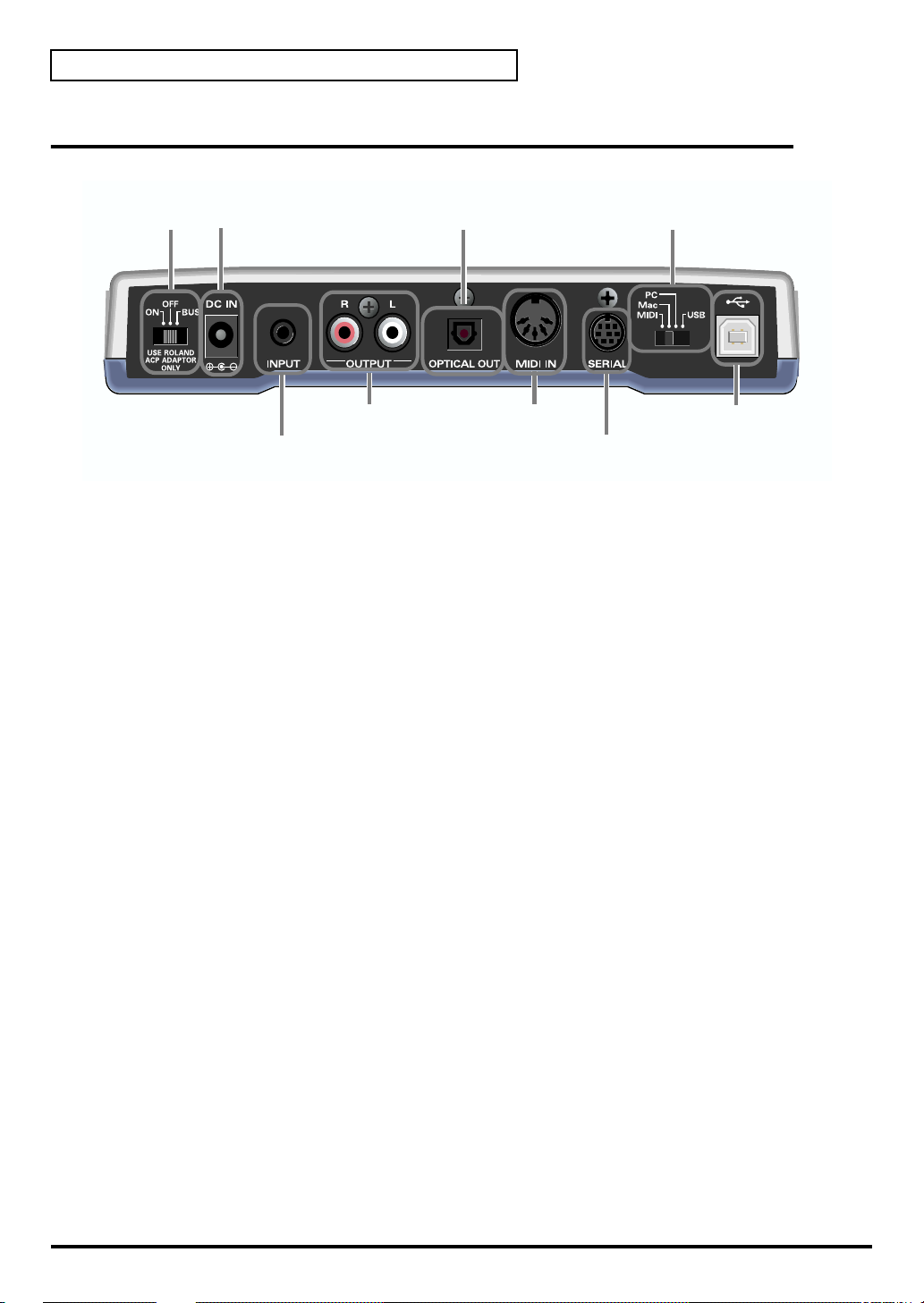
Rear Panel
fig.rear
Power Switch
AC Adaptor Jack
I
H
OPTICAL OUT Jack
L
Computer Switch
O
J
INPUT Jack
K
OUTPUT Jacks
MIDI IN Connector
M
N
SERIAL Connector
N
USB Connector
H. Power Switch
Provides for selection of either ON, OFF, or BUS as the setting for the power supply.
BUS POWER
The SD-20 can be operated on bus power.
"
Bus power
case, it is not necessary to connect the AC adaptor.
* Depending on the manner in which your computer supplies power to the USB connector, you may not be able
to run the SD-20 on bus power. In this case, please use the supplied AC adaptor.
" refers to power that is supplied to the SD-20 from a computer via a USB cable. In this
I. AC Adaptor Jack
Connect the supplied AC adaptor to this jack.
J. INPUT Jack
Connect the audio output jack of your computer sound card or audio device to this jack. The sound
that is input here will be mixed with the sound of the SD-20, and output from the
and the
headphone jack
.
OUTPUT jacks
K. OUTPUT Jacks
These jacks output the sound produced by the SD-20 sound generator in combination with the
sound that is input through the
INPUT jack
.
L. OPTICAL OUT Jack
This jack outputs the sound of the SD-20 sound generator. Sound being input through the INPUT
jack will not be mixed in.
M. MIDI IN Connector
Connect your MIDI keyboard or MIDI controller to this connector.
N. SERIAL Connector
Use this connector if you want to connect the SD-20 to your computer via a computer cable.
10
Names of things and what they do
O. Computer Switch
Set this switch as appropriate for the computer or interface to which the SD-20 is connected.
* If you change the setting of the computer switch, the SD-20 must be restarted. Turn the SD-20’s power
switch OFF, then ON again.
USB
Mac
PC
MIDI
If using a USB connection
If using a serial connection to Macintosh
If using a serial connection to Windows
If connected to an external MIDI device
P. USB Connector
Use this connector if you want to connect the SD-20 to your computer via a USB cable.
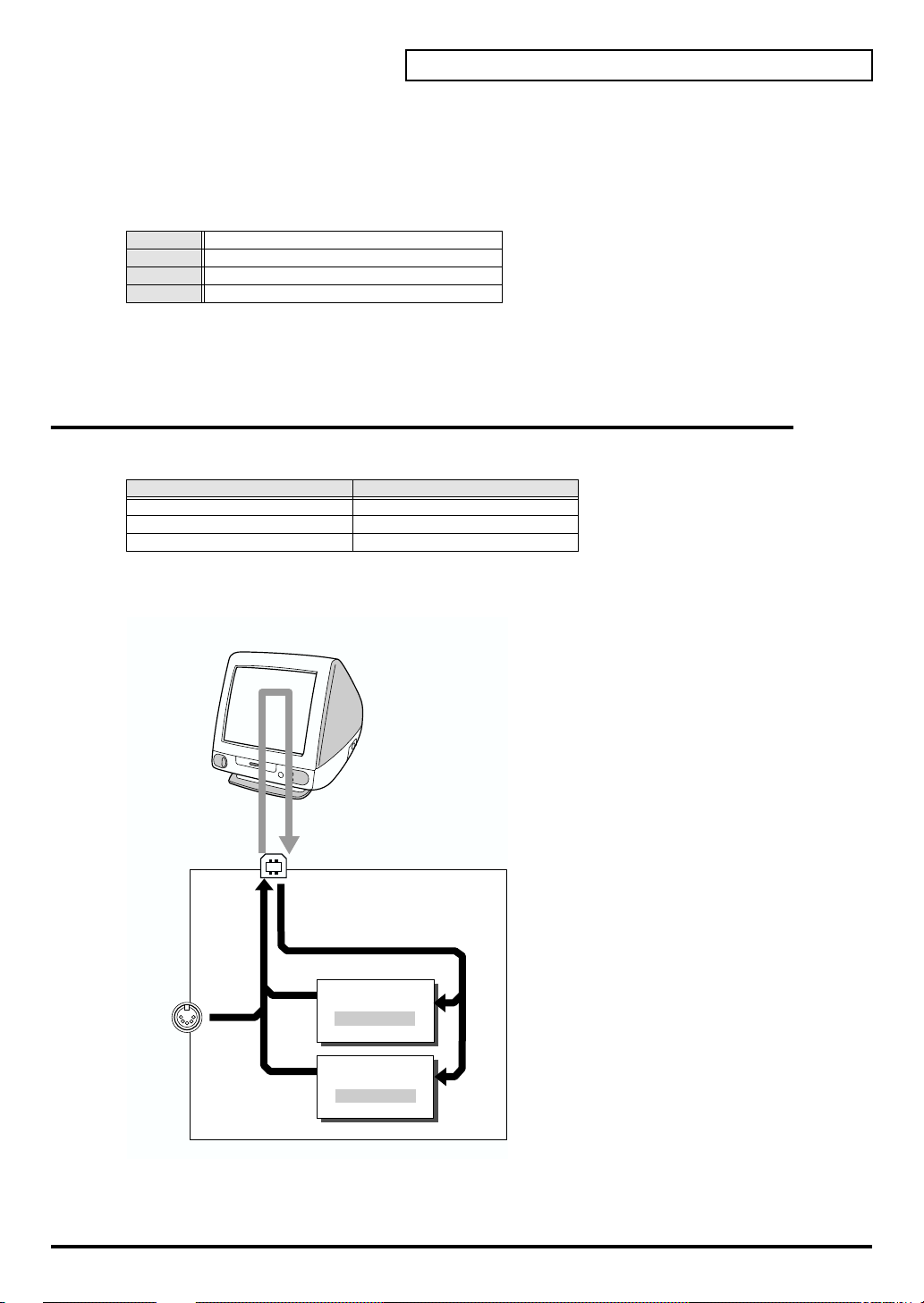
Exchanging MIDI data with your computer
There are three ways to connect the SD-20 to your computer and play it.
Method Number of available parts
Using the USB connector Maximum 32 parts
Using the serial connector Maximum 32 parts
Using the MIDI connector Maximum 16 parts
* Your computer needs to be equipped with a MIDI interface board or adaptor if you intend to use the MIDI
connector
THRU function: ON
fig.flow
MIDI IN
USB or SERIAL
Part group A
PART A1 - A16
Part group B
PART B1 - B16
The number of sound generator parts that
can be controlled will depend on your
software. Refer to the owner’s manual for
the software you are using.
SD-20
11
Names of things and what they do
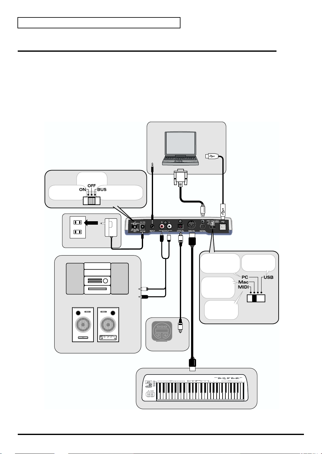
Basic connections
* To prevent malfunction and/or damage to speakers or other devices, always turn down the volume, and turn
off the power on all devices before making any connections.
* To avoid short circuits or broken connections, grasp the plug when disconnecting a cable.
* Use the included cables to make connections. If you are using a connection cable made by another
manufacturer, please note the following.
• Some connection cables contain a resistor. Do not use a cable with a built-in resistor to connect with the SD-90. Doing
fig.connect
so may make the sound extremely weak, or inaudible. For details on your cable, please contact its manufacturer.
Power switch
To turn on
the power
To turn off
the power
To use BUS power
Personal computer
Audio
cable
Computer cable
USB
connector
USB cable
AC adaptor
Stereo set
Powered speaker
LINE OUT
Audio
cable
Optical digital
MD
cable
DIGITAL
INPUT
MIDI OUT
When connecting via a
computer cable to a
Windows machine
When
connecting via a
computer cable
to a Macintosh
When controlling
the SD-20 from a
MIDI device
MIDI cable
MIDI keyboard etc..
When connecting
via a USB cable
Computer switch
12
About the sound generator modes
The SD-20 has four sound generator modes: Native, GM2, GS, and XGlite. GM2 and Native modes
offer three sound sets.
■
Native mode
This mode is unique to the SD-20. It provides three sound sets that can be switched using MIDI
bank select messages.
The way in which sounds are selected is different than in GM2 mode. For this reason, song data
you create in Native mode will not play back correctly on GM2 sound modules other than the SD-
20.
Other functions are the same as in GM2 mode.
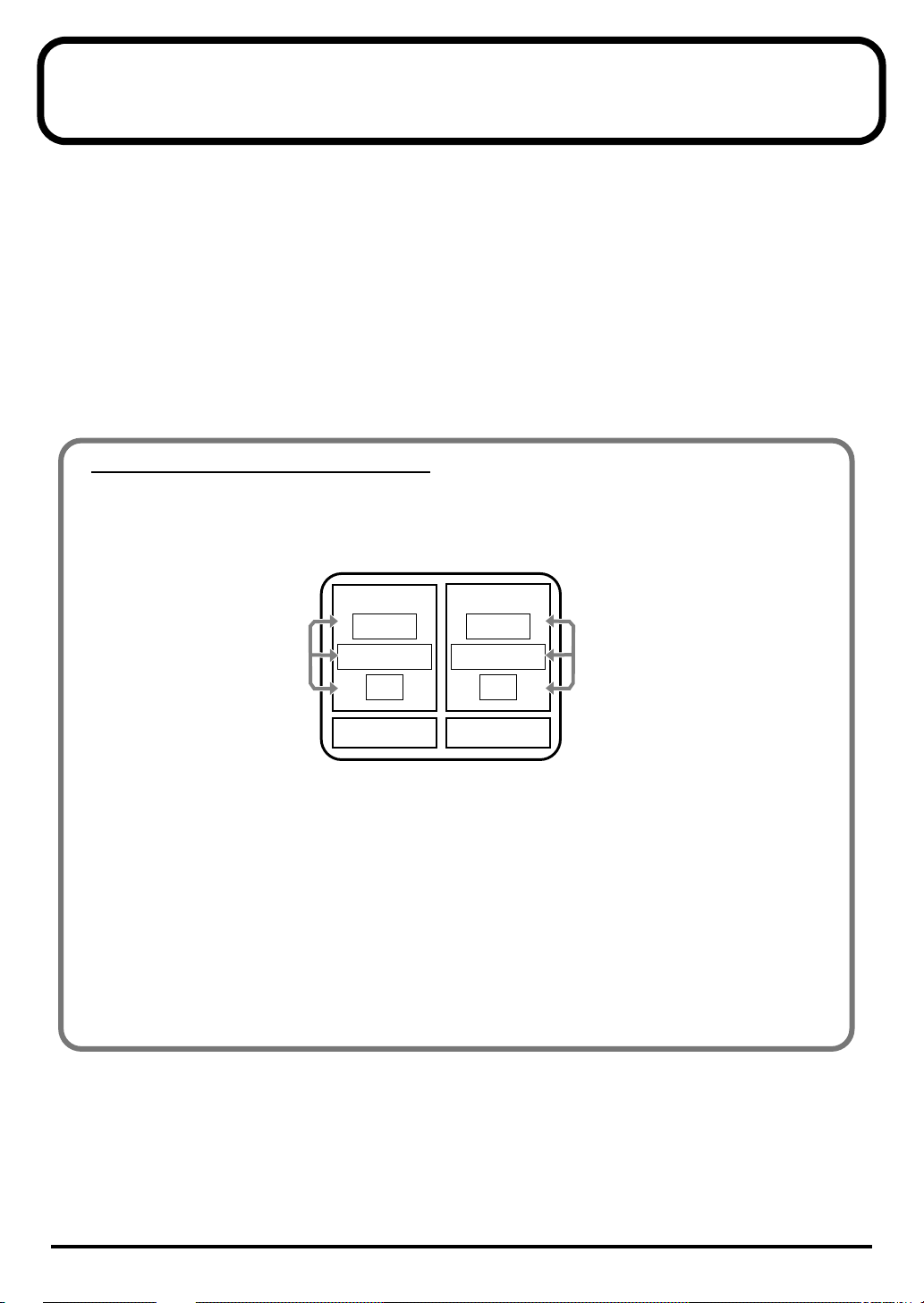
Sound sets in GM2/Native modes
The sound sets in GM2 mode and Native mode consist of three variations, which are classified
according to their characteristics.
fig.1
SD-20
Use NRPN or
exclusive messages
to switch
GM2
Classical
Contemporary
Solo
GS
Native
Classical
Contemporary
Solo
XGlite
Use bank
select to switch
Classical
This is the basic sound set that blends well into an ensemble. This set is also used when GM2 data
compatibility is important.
Contemporary
This sound set emphasizes the realism of each individual instrument. It contains numerous sounds
that use velocity switching for expressive dynamics.
Solo
This sound set contains mainly sounds that are designed to be distinctive when used to play solos.
These sounds include spacious stereo-sampled sounds, as well as sounds that are switched by
velocity.
13

About the sound generator modes
■ GM2 mode
This sound generator mode is compatible with the “GM2” sound generator format.
GM2 is “recommended practice,” and it is backwardly compatible with GM. It was created in order
to allow more sophisticated performance expression and greater compatibility. It includes detailed
definitions concerning sound editing and the use of effects (things that weren’t covered by the
earlier GM format), and it also expands the sound set. GM2-compatible sound generators will
correctly play back music data bearing either the GM or GM2 logos.
When it is necessary to make a distinction, this manual will sometimes refer to “GM1” to indicate
the earlier GM format which does not include the extended specifications of GM2.
■ GS mode
This sound generator mode supports the “GS” sound generator format promoted by Roland
Corporation.
In addition to the General MIDI functionality, this format expands the sound set, and also enhances
compatibility by providing detailed specifications for functionality such as sound editing and
effects (reverb and chorus). For flexibility in meeting future needs, it also provides for the addition
of new sounds and expanded functionality. Since the GS format is compatible with GM, it allows
GM scores to be played in the same way as GS music data (music data created in conformity with
the GS format).
* It is not possible to edit GS mode sound generator parameters from the panel of the SD-20.
■ XGlite mode
XG is a sound generator format promoted by Yamaha Corporation, which is based on GM1
(General MIDI 1). It provides detailed specifications concerning expansion of the sound sets,
editing methods, and effects structures and types.
XGlite is a reduced-functionality (“lite”) version of XG, which allows simple playback of XG music
data on a sound generator bearing the XGlite logo. Since XGlite has some limitations on the
parameters and effects that can be controlled, the XG music data may sound different than the
original data.
* It is not possible to edit XGlite mode sound generator parameters from the panel of the SD-20.
14

About parts and sounds
The SD-20 is able to produce 32 different sounds at once. A sound generator such as the SD-20 that
is able to produce many different sounds simultaneously is called a “multitimbral sound
module.” “Timbre” refers to the unique characteristics that result in the sound of one instrument
being different from that of another. The ability to simultaneously produce 32 different instrument
sounds means that, using the analogy of an orchestra, you can produce an ensemble consisting of
32 different instrumental parts. On the SD-20, the sound produced by each part is called an
Instrument (“Instrument list (GM2 / Native mode) ”(p. 72)). You can assign a desired instrument
to each of the 32 parts, creating a 32-part ensemble.
Different types of part
The SD-20 has 32 parts, which are divided into groups A and B. Each group is numbered from 01-
16; i.e., A01-A16 and B01-B16.
Each part can be set either as an Inst part or a Drum part. Inst parts are used to play melody, bass,
etc. Drum parts are used to play percussion-type sounds. This setting is called the Part Mode.
By default, the following part mode is selected for each part.
Part mode Corresponding parts
Inst part A01-09, A11-16, B01-09, B11-16
Drum part A10, B10
When using the MIDI connector to play the SD-20
When using the MIDI connector to play the SD-20, MIDI IN is correlated with Group A.
In other words, the MIDI messages received at MIDI IN will be passed to the Group A parts.
For example, MIDI messages arriving on channel 5 at MIDI IN will sound part 5 of group A (A05)
(at the default settings). When using the MIDI IN connector to play the SD-20, it is not possible to
play the Group B parts.
About the sound generator modes
Polyphony and voices
Each of the SD-20’s sounds consist of units called “voices.” There is a limit to the number of voices
that can be used, and the SD-20 is able to use 64 voices simultaneously. Some sounds
(instruments) use more than one voice (“Instrument list (GM2 / Native mode) ”(p. 72)). The main
reason that an instrument uses some voices is so that velocity can be used to shift between different
sounds, or so that multiple sounds can be layered to create a richer tone.
When you attempt to play more than 64 voices on the SD-20, the most-recently played note will be
given priority, and the oldest of the currently-sounding notes will be turned off one by one. If you
are using only instruments that consist of only one voice, you will be able to play 64 notes
simultaneously. However, if you use instruments that consist of two or four voices, fewer than 64
notes can be played simultaneously. Even if a MIDI note-off message is received, a voice will
continue to be used as long as that note continues to sound. You need to remain aware of this,
particularly when using sounds that have a long release time.
15
Getting connected and installing drivers (Windows)
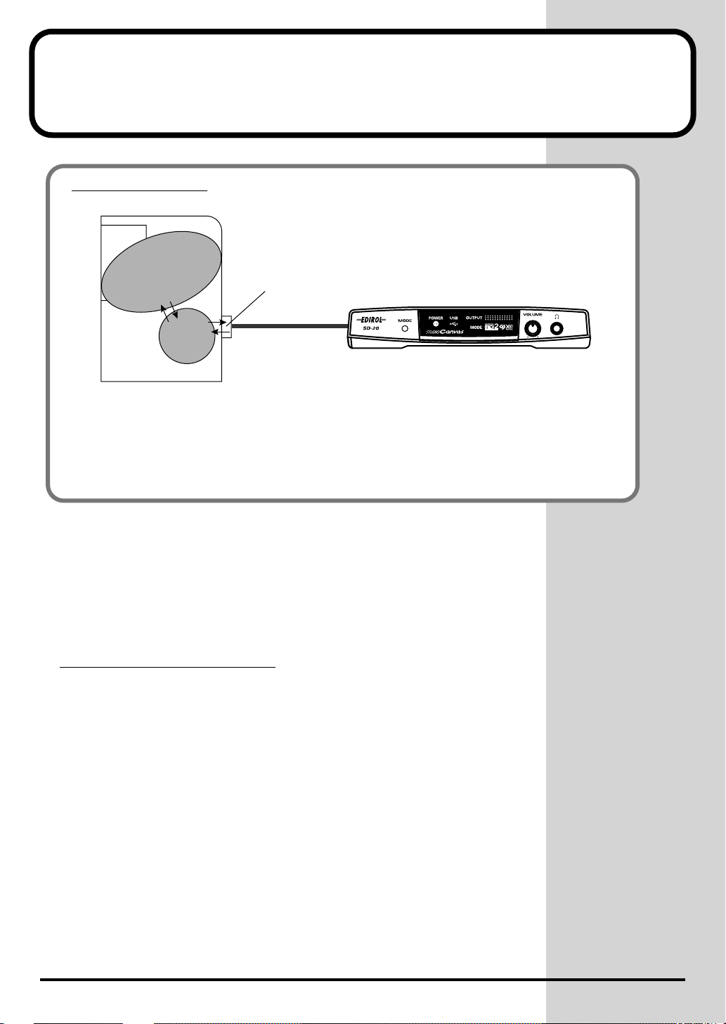
What is a driver?
fig.2-0
Application
Driver
Computer
A “driver” is software that transfers data between the SD-20 and application software
running on your computer, when your computer and the SD-20 are connected by a USB
cable. The driver sends data from your application to the SD-20, and from the SD-20 to your
application.
The SD-20 is able to operate using the “BUS power” that is supplied via the
USB cable. This means that the supplied AC adaptor is not necessary.
However, if you are using a USB hub, or if not enough power can be supplied
via USB, the SD-20 may not operate correctly. In this case, connect the
supplied AC adaptor power supply to the SD-20.
When installing the driver, you must connect the AC adaptor and turn the
POWER switch ON.
USB/Serial
port
USB/Serial
Cable
SD-20
Which type of connection?
You can either use the USB cable, or use the computer cable to make a serial
connection. Depending on the type of connection you are using, install the
appropriate driver and make the appropriate settings.
16
USB connection................................................(p. 17)
Serial connection..............................................(p. 28)
USB connection
The following items are required for connections and installation. Please
have the following items ready.
• SD-20
• AC adaptor
• USB cable
• CD-ROM
The installation procedure will differ depending on your system.
Please proceed to one of the following sections, depending on the system you
use.
• Windows XP users ..................................................... (p. 17)
• Windows 2000 users................................................... (p. 22)
• Windows Me/98 users .............................................. (p. 26)
■ Windows XP users
1
With the SD-20 disconnected, start up Windows.
Disconnect all USB cables except for a USB keyboard and USB mouse (if
used).
2
Open the System Properties dialog box.
Getting connected and installing drivers (Windows)
If you are using Windows
XP Professional, you must
log on using a user name
with an administrative
account type (e.g.,
Administrator). For details
on user accounts, please
consult the system
administrator of your
computer.
1. Click the Windows Start menu, and from the menu, select Control
Panel .
2. In " Pick a category," click "Performance and Maintenance."
3. In "or pick a Control Panel icon," click the System icon.
fig.2-1
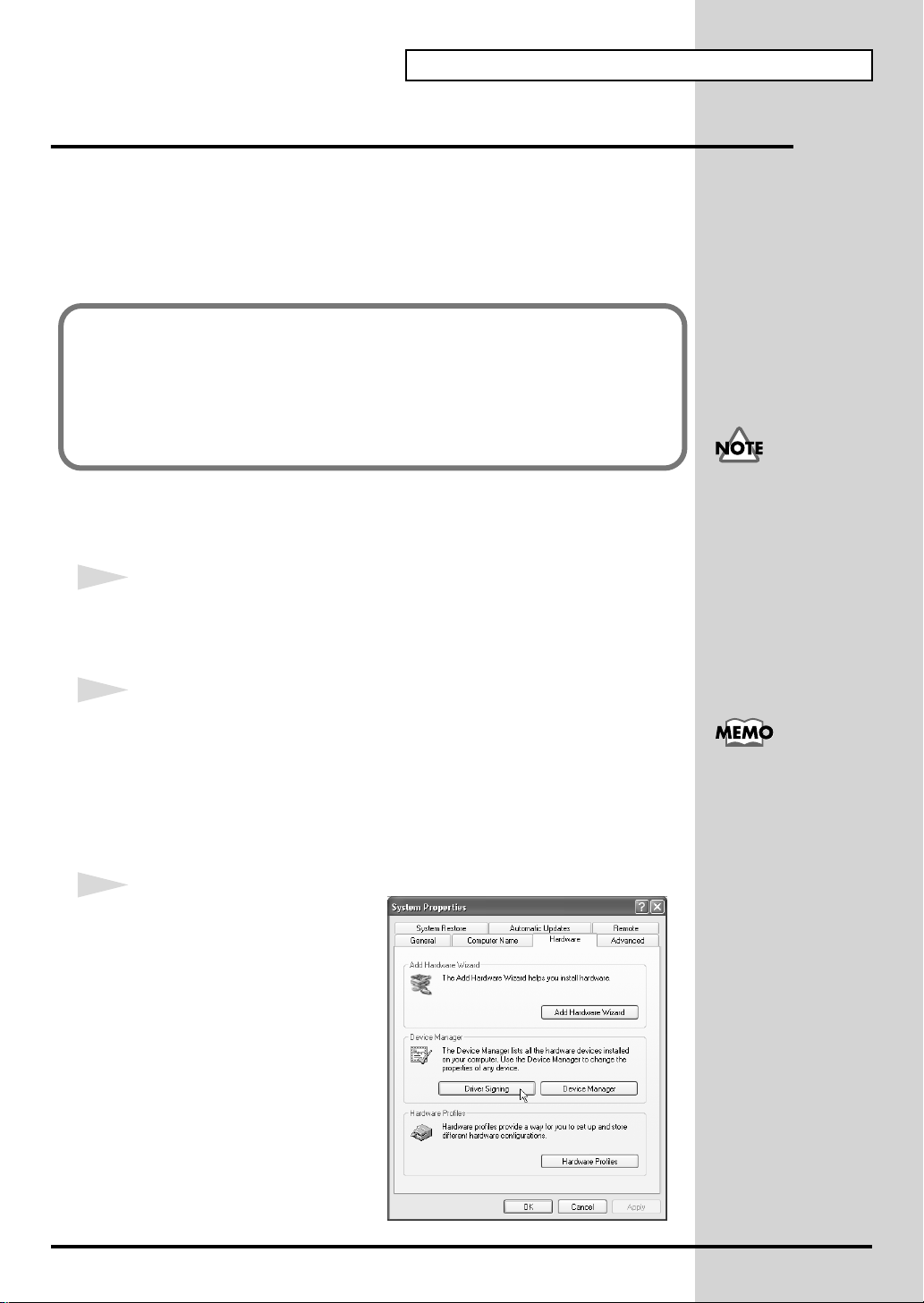
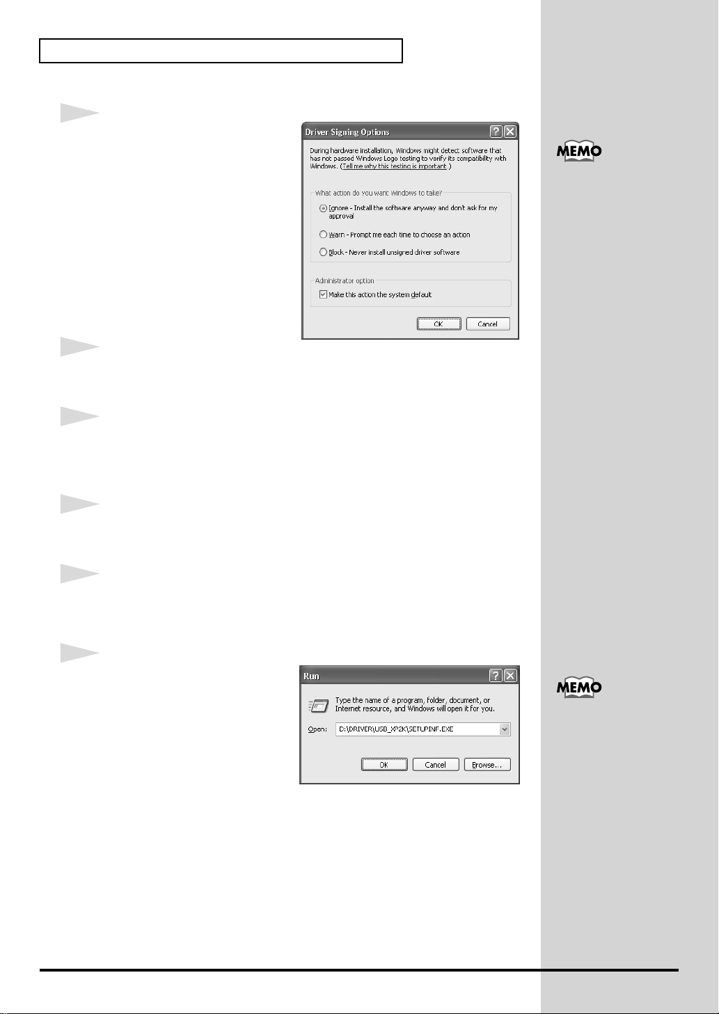
3
Open the Driver Signing
Options dialog box.
Click the Hardware tab, and then
click [Driver Signing].
Depending on how your
system is set up, the
System icon may be
displayed directly in the
Control Panel (the Classic
display). In this case,
double-click the System
icon.
17
Getting connected and installing drivers (Windows)
fig.2-2
4
Make sure that “What action do
you want Windows to take?” is
set to “Ignore.”
If it is set to “Ignore”, simply click
[OK].
If it is not set to “Ignore”, make a
note of the current setting
(“Warn” or “Block”). Then change
the setting to “Ignore” and click
[OK]
5
Close the System Properties dialog box.
Click [OK].
6
Exit all currently running software (applications).
If you changed “What
action do you want
Windows to take?” in
step 4, you must restore
the previous setting after
you have installed the
driver. (->If you changed
“What action do you
want Windows to take?”
(p. 21))
Also close any open windows. If you are using virus checking or similar
software, be sure to exit it as well.
7
Prepare the CD-ROM.
Insert the CD-ROM into the CD-ROM drive of your computer.
8
Open the “Run...” dialog box.
Click the Windows start button. From the menu that appears, select “Run...”
fig.2-3_30
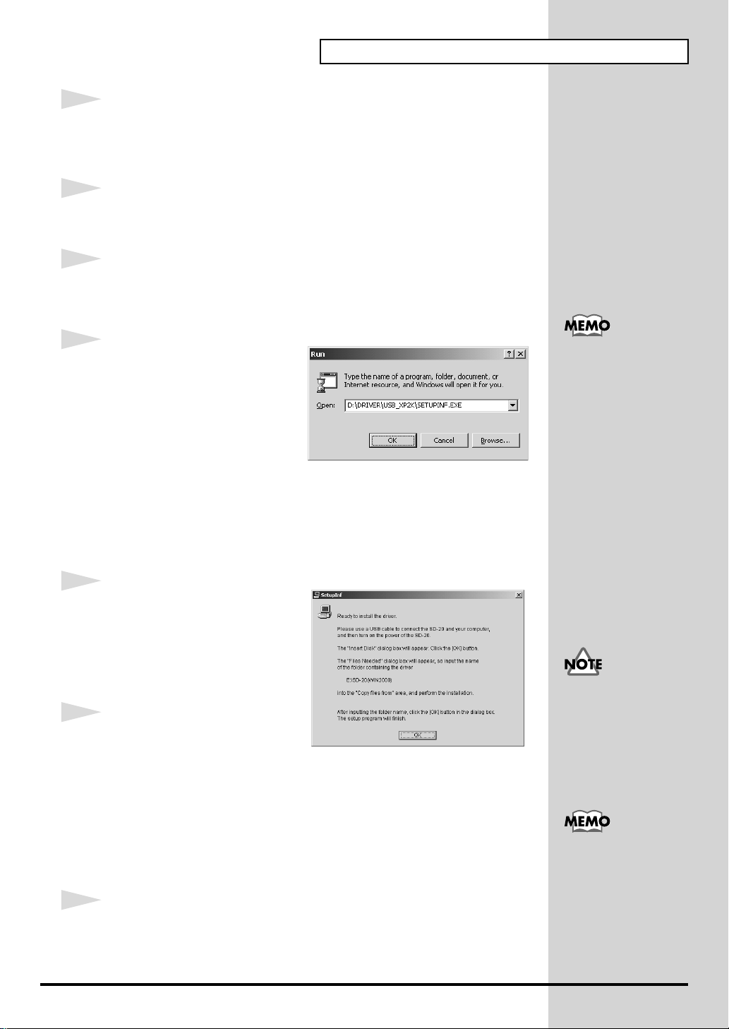
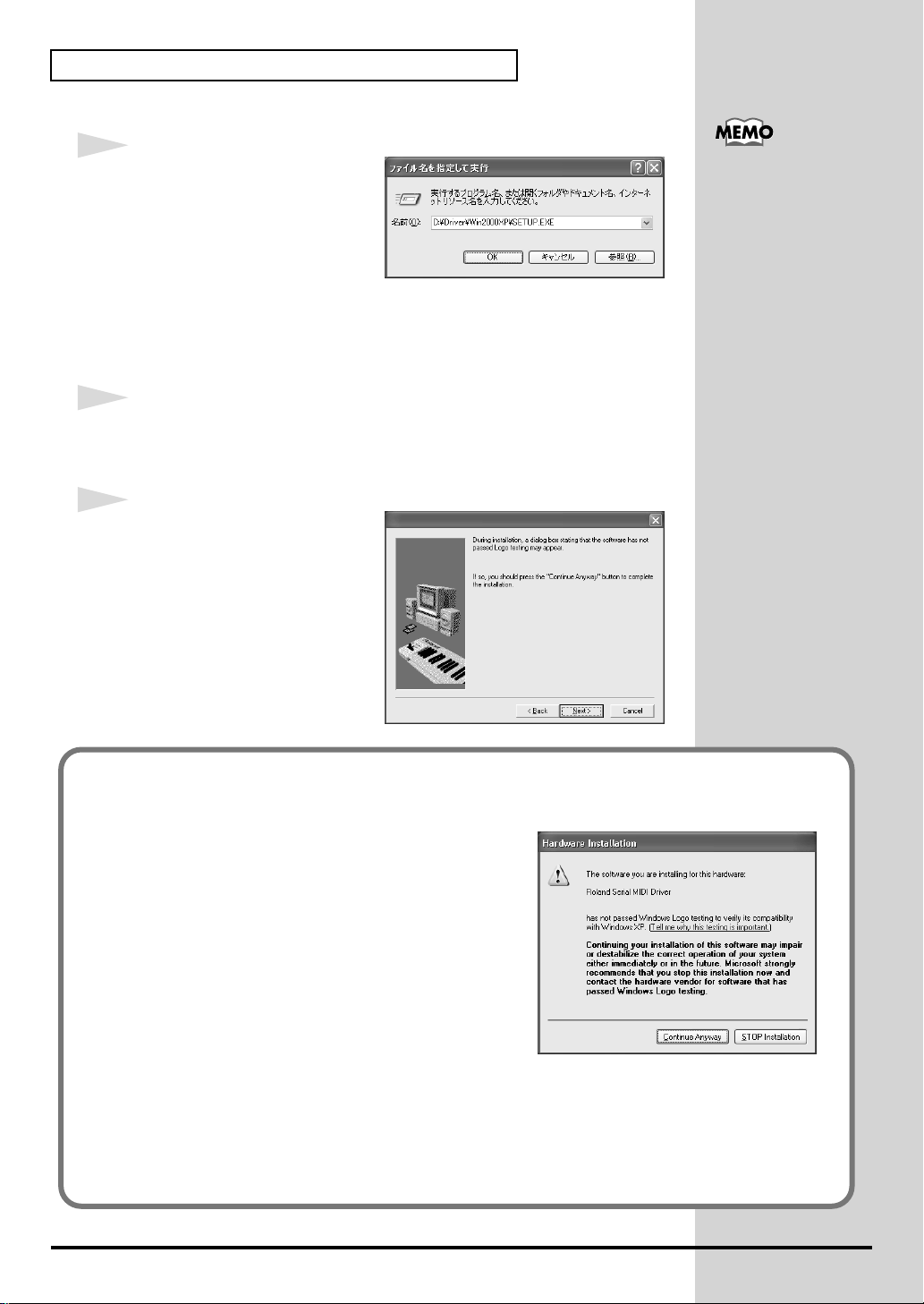
9
In the dialog box that appears,
input the following into the
“Open” field, and click [OK].
D:\DRIVER\USB_XP2K\SETUPINF.EXE
* The drive name “D:” may be different for your system. Specify the drive name of your
CD-ROM drive.
In this manual, the location
of folders and files is given
in terms of the file path,
using \ as the delimiter. For
example,
USB_XP2K\SETUPINF.E
XE indicates the
SETUPINF.EXE file found
in the USB_XP2K folder.
18
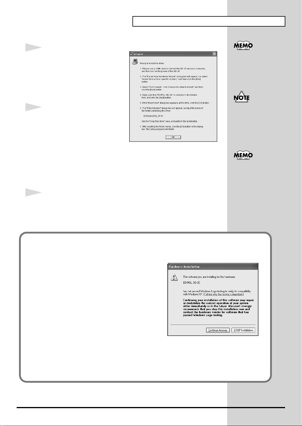
fig.2-4_30
b
b
10
The SetupInf dialog box will
appear.
You are now ready to install the
driver.
* Do not click [OK] at this time.
Getting connected and installing drivers (Windows)
If a message of “The
driver is already
installed” appears, you
can connect the SD-20 to
your computer and use it.
11
Connect the SD-20.
1. Set the computer switch of the
SD-20 to USB.
2. With the SD-20’s power switch turned off, connect it to the AC
adaptor.
3. Plug the AC adaptor into an AC power outlet.
4. Use the USB cable to connect the SD-20 to your computer.
12
Set the SD-20’s power switch to the ON position.
Near the task bar, your computer will indicate “Found New Hardware.”
Please wait.
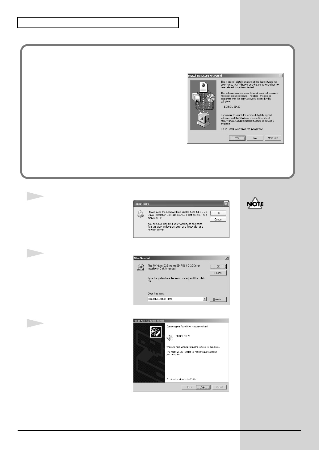
If in step 4 the “What action do you want Windows to take?” setting was not set to
“Ignore”, a “Digital signature not found” dialog box will appear.
fig.2-5
If “What action do you want Windows to
take?” is set to “Warn,”
Even if you will normally
e using the SD-20 with
BUS power, please use the
AC adaptor while you are
installing the driver and
making settings.
This unit is equipped with
protection circuit. A brief
interval (a few seconds)
after power up is required
efore the unit will operate
normally.
1. Click [Continue Anyway].
2. Continue the installation.
If “What action do you want Windows to
take?” is set to “Block”
1. Click [OK].
2. When the “Found New Hardware Wizard”
appears, click [Finish].
3. Perform the installation as described in the “Troubleshooting” section on Device
Manager shows “?”, “!”, or “USB Composite Device” (p. 60).
19

Getting connected and installing drivers (Windows)
fig.2-6
13
The Found New Hardware
wizard will appear.
Make sure that the screen
indicates “EDIROL SD-20,” select
“Install from a list or specific
location (Advanced),” and click
[Next].
fig.2-7
14
The screen will indicate “Please
choose your search and
installation options.”
Select “Don’t search. I will
choose the driver to install,” and
click [Next].
fig.2-8_20
15
Make sure that the “Model” field
indicates “EDIROL SD-20,” and
click [Next]. Driver installation
will begin.
fig.2-9_30
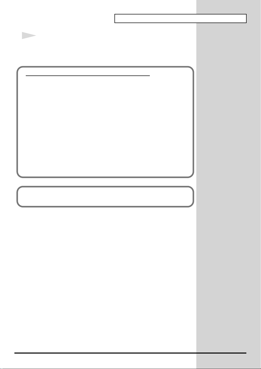
16
The Insert Disk dialog box will
appear.
Click [OK].
20
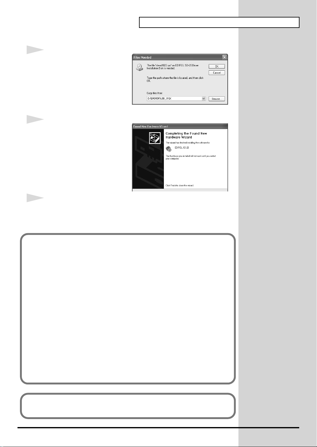
fig.2-10_30
17
The Files Needed dialog box will
appear.
In the "Copy files from" area, type
"D:\DRIVER\USB_XP2K" and
click [OK].
fig.2-11_20
18
The Found New Hardware
wizard will appear.
Make sure that the display
indicates "EDIROL SD-20," and
click [Finish].
Wait until "Found New
Hardware" appears near the
taskbar.
Getting connected and installing drivers (Windows)
19
Restart Windows.
When driver installation has been completed, the System Setting Change
dialog box will appear. Click [Yes].
If you changed “What action do you want Windows to take?”
If you changed the What action do you want Windows to take? setting in
step 5, restore the original setting after Windows restarts.
1. If you are using Windows XP Professional, log on to Windows using
the user name of an administrative account (e.g., Administrator).
2. Click the Windows start menu, and from the menu, select Control
Panel.
3. In "Pick a category," click "Performance and Maintenance."
4. In "or pick a Control Panel icon," click the System icon. The System
Properties dialog box will appear.
5. Click the Hardware tab, and then click [Driver Signing]. The Driver
Signing Options dialog box will appear.
6. Return the What action do you want Windows to take? setting to the
original setting (either “Warn” or “Block”), and click [OK].
7. Click [OK]. The System properties dialog box will close.
Nest, you need to make the driver settings.
(-> Settings and checking (p. 38))
21
Getting connected and installing drivers (Windows)
■ Windows 2000 users
1
With the SD-20 disconnected, start up Windows.
Disconnect all USB cables except for a USB keyboard and USB mouse (if
used).
2
Log on to Windows as a user with administrative privileges (such as
Administrator).
3
Open the System Properties dialog box.
Click the Windows Start button, and from the menu that appears, select
Settings | Control Panel. In Control Panel, double-click the System icon.
fig.2-12
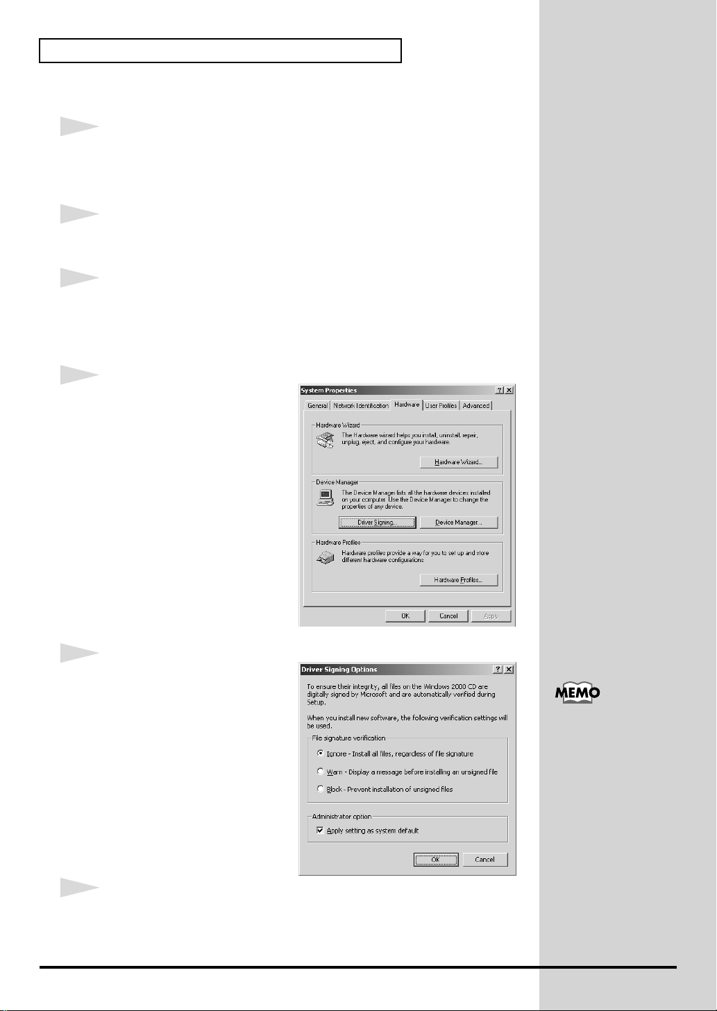
4
Open the Driver Signing
Options dialog box.
Click the Hardware tab, and then
click [Driver Signing].
22
fig.2-13_50
5
Make sure that “File signature
verification” is set to “Ignore.”
If it is set to “Ignore”, simply click
[OK].
If it is not set to “Ignore”, make a
note of the current setting
(“Warn” or “Block”). Then change
the setting to “Ignore” and click
[OK].
6
Close the System Properties dialog box.
Click [OK].
If you changed the “File
signature verification”
setting in step 5, restore
the original setting after
Windows restarts. (->If
you changed “File
signature verification” (p.
25))
7
b
b
Exit all currently running software (applications).
Also close any open windows. If you are using virus checking or similar
software, be sure to exit it as well.
8
Prepare the CD-ROM.
Insert the CD-ROM into the CD-ROM drive of your computer.
9
Open the “Run...” dialog box.
Click the Windows Start button. From the menu that appears, select “Run...”
fig.2-14_40
Getting connected and installing drivers (Windows)
10
In the dialog box that appears,
input the following into the
“Open” field, and click [OK].
D:\DRIVER\USB_XP2K\SETUPINF.EXE
* The drive name “D:” may be different for your system. Specify the drive name of your
CD-ROM drive.
fig.2-15_40
11
The SETUPINF dialog box will
appear.
You are now ready to install the
driver.
* Do not click [OK] at this time.
12
Connect the SD-20.
1. Set the computer switch of the SD-20 to USB.
In this manual, the location
of folders and files is given
in terms of the file path,
using \ as the delimiter. For
example,
USB_XP2K\SETUPINF.E
XE indicates the
SETUPINF.EXE file found
in the USB_XP2K folder.
Even if you will normally
e using the SD-20 with
BUS power, please use the
AC adaptor while you are
installing the driver and
making settings.
2. With the SD-20’s power switch turned off, connect it to the AC
adaptor.
3. Plug the AC adaptor into an AC power outlet.
4. Use the USB cable to connect the SD-20 to your computer.
13
Set the SD-20’s power switch to the ON position.
This unit is equipped with
protection circuit. A brief
interval (a few seconds)
after power up is required
efore the unit will operate
normally.
23
Getting connected and installing drivers (Windows)
b
If in step 5 the “File signature verification” setting was not set to “Ignore”,
a “Digital signature not found” dialog box will appear.
fig.2-16_30
If “File signature verification” is set to “Warn,”
1. Click [Yes].
2. Continue the installation.
If “File signature verification” is set to “Block”
1. Click [OK].
2. When the “New hardware detection wizard”
appears, click [Finish].
3. Perform the installation as described in the
“Troubleshooting” section on Device Manager shows “?”, “!”, or
“USB Composite Device” (p. 60).
fig.2-17_30
14
The Insert Disk dialog box will
appear.
Click [OK].
fig.2-18_30
If the Insert disk dialog
ox does not appear,
please read The The
“Insert Disk” dialog box
does not appear (p. 60))
15
The Files Needed dialog box will
appear.
In the "Copy files from" area, type
"D:\DRIVER\USB_XP2K" and
click [OK].
fig.2-17b_30
16
The “Found New Hardware
Wizard” may be displayed.
Verify that “EDIROL SD-20” is
displayed, and click [Finish].
24
17
Restart Windows.
The System Settings Change dialog box may appear. Click [Yes].
Windows will restart automatically.
If you changed “File signature verification”
If you changed the “File signature verification” setting in step 5, restore the
original setting after Windows restarts.
1. After Windows restarts, log in to Windows as a user with
administrative privileges, (such as Administrator).
2. In the Windows desktop, right-click the My Computer icon, and from
the menu that appears, select Properties. The System Properties
dialog box will appear.
3. Click the Hardware tab, and then click [Driver signature]. The Driver
Signing Options dialog box will appear.
4. Return the “File signature verification” setting to the original setting
(either “Warn” or “Block”), and click [OK].
Getting connected and installing drivers (Windows)
5. Click [OK]. The System properties dialog box will close.
Nest, you need to make the driver settings.
(-> Settings and checking (p. 38)
25
Getting connected and installing drivers (Windows)
■ Windows Me/98 users
1
With the SD-20 disconnected, start up Windows.
Disconnect all USB cables except for a USB keyboard and USB mouse (if
used).
2
Exit all currently running software (applications).
Also close any open windows. If you are using virus checking or similar
software, be sure to exit it as well.
3
Prepare the CD-ROM.
Insert the CD-ROM into the CD-ROM drive of your computer.
4
Open the “Run...” dialog box.
Click the Windows Start button.
From the menu that appears, select “Run...”
fig.2-19a_30
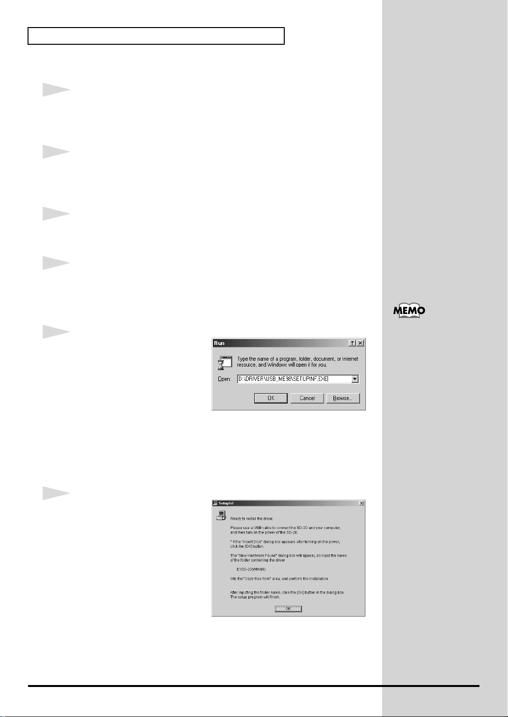
5
In the dialog box that appears,
input the following into the
“Open” field, and click [OK].
\
D:\DRIVER\USB_ME98\SETUPINF.EXE
In this manual, the location
of folders and files is given
in terms of the file path,
using \ as the delimiter. For
example,
USB_ME98\SETUPINF.E
XE indicates the
SETUPINF.EXE file found
in the USB_ME98 folder.
26
* The drive name “D:” may be different for your system. Specify the drive name of your
CD-ROM drive.
fig.2-19_30
6
The SETUPINF dialog box will
appear.
You are now ready to install the
driver.
* Do not click [OK] at this time.

7
b
b
Connect the SD-20.
1. Set the computer switch of the SD-20 to USB.
2. With the SD-20’s power switch turned off, connect it to the AC
adaptor.
3. Plug the AC adaptor into an AC power outlet.
Getting connected and installing drivers (Windows)
Even if you will normally
e using the SD-20 with
BUS power, please use the
AC adaptor while you are
installing the driver and
making settings.
4. Use the USB cable to connect the SD-20 to your computer.
5
Set the SD-20’s power switch to the ON position.
fig.2-20_30
6
If you are using Windows 98, an
Insert Disk dialog box will
appear.
Click [OK].
fig.2-21a_40
7
The New Hardware Found
dialog box will appear.
In the "Copy files from" area, type
"D:\DRIVER\USB_ME98" and
click [OK].
8
Once the driver has been installed, New Hardware Founddialog box will
close.
In the SETUPINF dialog box, click [OK]. The SETUPINF dialog box will
close.
This unit is equipped with
a protection circuit. A brief
interval (a few seconds)
after power up is required
efore the unit will operate
normally.
If you are using Windows
98 and the Insert Disk
dialog box dose not
appear, please read The
“Insert Disk” dialog box
does not appear (p. 60).
If the New Hardware
Found dialog box does not
appear, re-install the
driver using the same
procedure as described in
The “Insert Disk” dialog
box does not appear (p.
60).
Nest, you need to make the driver settings.
(-> Settings and checking (p. 38)
27
Getting connected and installing drivers (Windows)
Serial connection
The following items are required for connections and installation. Please
have the following items ready.
• SD-20
• AC adaptor
• Computer cable
• CD-ROM
The installation procedure will differ depending on your system.
Please proceed to one of the following sections, depending on the system you
use.
• Windows XP users ..................................................... (p. 28)
• Windows 2000 users................................................... (p. 32)
• Windows Me/98 users .............................................. (p. 36)
■ Windows XP users
1
Make sure that the power is turned off for the SD-20, your computer, and all
peripheral devices.
2
Set the computer switch of the SD-20 to PC.
3
Use the computer cable to connect the serial connector of your computer to
the SD-20.
4
With the SD-20’s power switch turned off, connect it to the AC adaptor.
5
Plug the AC adaptor into an AC power outlet.
6
Turn on the power of the SD-20 and your computer, and start up Windows.
7
Open the System Properties dialog box.
If you are using Windows
XP Professional, you must
log on using a user name
with an administrative
account type (e.g.,
Administrator). For details
on user accounts, please
consult the system
administrator of your
computer.
For details on connections,
refer to Basic
connections (p. 12)
28
1. Click the Windows start menu, and from the menu, select Control
Panel.
2. In “Pick a category,” click “Performance and Maintenance.”
3. In “or pick a Control Panel icon,” click the System icon.
Depending on how your
system is set up, the
System icon may be
displayed directly in the
Control Panel (the Classic
display). In this case,
double-click the System
icon.
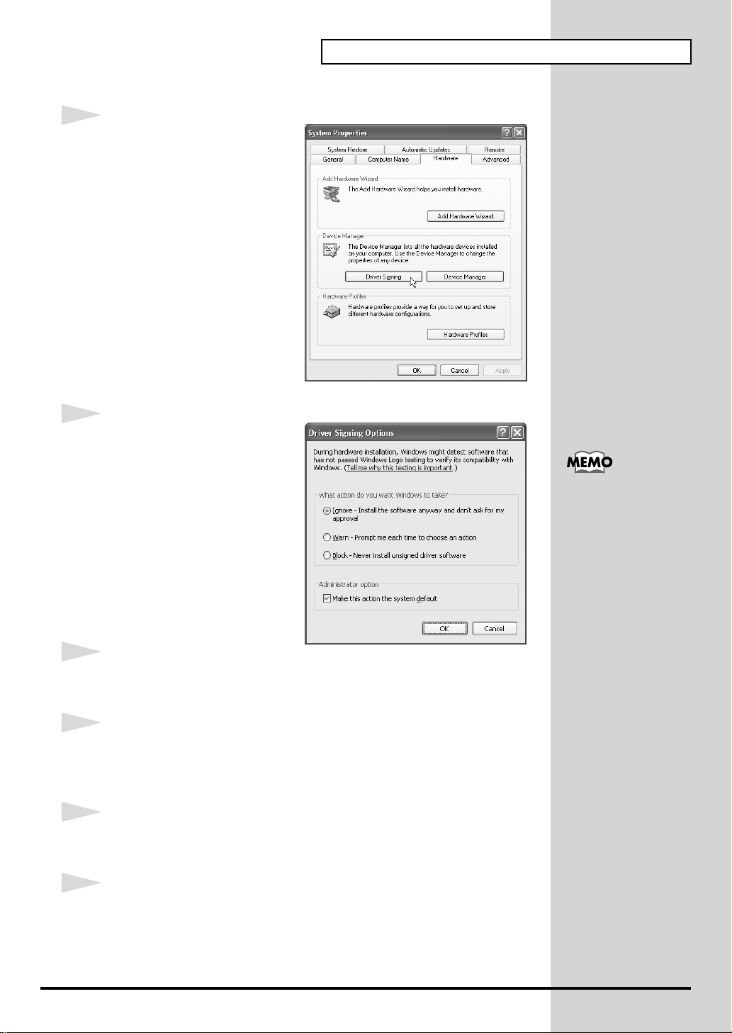
fig.2-1
8
Open the Driver Signing
Options dialog box.
Click the Hardware tab, and then
click [Driver Signing].
fig.2-2
9
Make sure that “What action do
you want Windows to take?” is
set to “Ignore.”
If it is set to “Ignore”, simply click
[OK].
If it is not set to “Ignore”, make a
note of the current setting
(“Warn” or “Block”). Then change
the setting to “Ignore” and click
[OK]
10
Close the System Properties dialog box.
Getting connected and installing drivers (Windows)
If you changed “What
action do you want
Windows to take?” in
step 8, you must restore
the previous setting after
you have installed the
driver. (->If you changed
“What action do you
want Windows to take?”
(p. 21))
Click [OK].
11
Exit all currently running software (applications).
Also close any open windows. If you are using virus checking or similar
software, be sure to exit it as well.
12
Prepare the CD-ROM.
Insert the CD-ROM into the CD-ROM drive of your computer.
13
Open the “Run...” dialog box.
Click the Windows start button. From the menu that appears, select “Run...”
29
Getting connected and installing drivers (Windows)
fig.2-22_40
14
In the dialog box that appears,
input the following into the
“Open” field, and click [OK].
D:\DRIVER\SER_XP2K\SETUP.EXE
* The drive name “D:” may be different for your system. Specify the drive name of your
CD-ROM drive.
15
The Welcome dialog box will appear.
Click [Next].
fig.2-22b_30
16
A dialog box like the following
will appear.
Click [Next].
In this manual, the location
of folders and files is given
in terms of the file path,
using \ as the delimiter. For
example,
SER_XP2K\SETUP.EXE
indicates the SETUP.EXE
file found in the
SER_XP2K folder.
30
If in step 9 the “What action do you want Windows to take?” setting was not set to
“Ignore”, a “Hardware Installation” dialog box will appear.
fig.2-22c_30
If “What action do you want Windows to take?”
is set to “Warn,”
1. Click [Continue Anyway].
2. Continue the installation.
If “What action do you want Windows to take?”
is set to “Block”
1. Click [OK].
2. When the “Found New Hardware Wizard”
appears, click [Finish].
3. Perform the installation as described in the “Troubleshooting” section on Device
Manager shows “?”, “!”, or “USB Composite Device” (p. 60).
 Loading...