

Roland Corporation MMP-2 Owner's Manual
Owner’s manual
Before using this unit, carefully read the sections entitled: “USING THE UNIT
SAFELY”(p. 2), and “IMPORTANT NOTES”(p. 6). These sections provide
important information concerning the proper operation of the unit.
Additionally, in order to feel assured that you have gained a good grasp of
every feature provided by your new unit, Owner’s manual should be read in
its entirety. The manual should be saved and kept on hand as a convenient
reference.
All rights reserved.
No part of this publication may be reproduced in any form
without the written permission of ROLAND CORPORATION.
http://www.roland.co.jp/
Copyright © 2002 ROLAND CORPORATION
USING THE UNIT SAFELY
Used for instructions intended to alert
the user to the risk of death or severe
injury should the unit be used
improperly.
Used for instructions intended to alert
the user to the risk of injury or material
damage should the unit be used
improperly.
* Material damage refers to damage or
other adverse effects caused with
respect to the home and all its
furnishings, as well to domestic
animals or pets.
• Before using this unit, make sure to read the
instructions below, and the Owner’s Manual.
................................................................................................
• Do not open or perform any internal modifications on the unit.
................................................................................................
• Do not attempt to repair the unit, or replace
parts within it (except when this manual
provides specific instructions directing you
to do so). Refer all servicing to your retailer,
the nearest Roland Service Center, or an
authorized Roland distributor, as listed on
the “Information” page.
................................................................................................
• Never use or store the unit in places that are:
• Subject to temperature extremes (e.g.,
direct sunlight in an enclosed vehicle, near
a heating duct, on top of heat-generating
equipment); or are
• Damp (e.g., baths, washrooms, on wet
floors); or are
• Humid; or are
• Exposed to rain; or are
• Dusty; or are
• Subject to high levels of vibration.
................................................................................................
• Make sure you always have the unit placed
so it is level and sure to remain stable. Never
place it on stands that could wobble, or on
inclined surfaces.
................................................................................................
The symbol alerts the user to important instructions
or warnings.The specific meaning of the symbol is
determined by the design contained within the
triangle. In the case of the symbol at left, it is used for
general cautions, warnings, or alerts to danger.
The symbol alerts the user to items that must never
be carried out (are forbidden). The specific thing that
must not be done is indicated by the design contained
within the circle. In the case of the symbol at left, it
means that the unit must never be disassembled.
The ● symbol alerts the user to things that must be
carried out. The specific thing that must be done is
indicated by the design contained within the circle. In
the case of the symbol at left, it means that the powercord plug must be unplugged from the outlet.
• The unit should be connected to a power
supply only of the type described in the
operating instructions, or as marked on the
unit.
................................................................................................
• Use only the attached power-supply cord.
.
................................................................................................
• Do not excessively twist or bend the power
cord, nor place heavy objects on it. Doing so
can damage the cord, producing severed
elements and short circuits. Damaged cords
are fire and shock hazards!
................................................................................................
• This unit, either alone or in combination with
an amplifier and headphones or speakers,
may be capable of producing sound levels
that could cause permanent hearing loss. Do
not operate for a long period of time at a high
volume level, or at a level that is uncomfortable. If you experience any hearing loss or
ringing in the ears, you should immediately
stop using the unit, and consult an audiologist.
................................................................................................
• Do not allow any objects (e.g., flammable
material, coins, pins); or liquids of any kind
(water, soft drinks, etc.) to penetrate the unit.
• In households with small children, an adult
should provide supervision until the child is
capable of following all the rules essential for
the safe operation of the unit.
................................................................................................
2
• Protect the unit from strong impact.
(Do not drop it!)
................................................................................................
• Do not force the unit’s power-supply cord to
share an outlet with an unreasonable number
of other devices. Be especially careful when
using extension cords—the total power used
by all devices you have connected to the
extension cord’s outlet must never exceed the
power rating (watts/amperes) for the
extension cord. Excessive loads can cause the
insulation on the cord to heat up and
eventually melt through.
................................................................................................
• Before using the unit in a foreign country,
consult with your retailer, the nearest Roland
Service Center, or an authorized Roland
distributor, as listed on the “Information”
page.
................................................................................................
• DO NOT play a CD-ROM disc on a conventional audio CD player. The resulting sound
may be of a level that could cause permanent
hearing loss. Damage to speakers or other
system components may result.
................................................................................................
USING THE UNIT SAFELY
• The unit should be located so that its location
or position does not interfere with its proper
ventilation.
................................................................................................
• Always grasp only the plug on the powersupply cord when plugging into, or
unplugging from, an outlet or this unit.
................................................................................................
• Try to prevent cords and cables from
becoming entangled. Also, all cords and
cables should be placed so they are out of the
reach of children.
................................................................................................
• Never climb on top of, nor place heavy
objects on the unit.
................................................................................................
• Never handle the power cord or its plugs
with wet hands when plugging into, or
unplugging from, an outlet or this unit.
................................................................................................
• Before moving the unit, disconnect the power
plug from the outlet, and pull out all cords
from external devices.
................................................................................................
• Before cleaning the unit, turn off the power
and unplug the power cord from the outlet
(p. 18).
................................................................................................
• Whenever you suspect the possibility of
lightning in your area, pull the plug on the
power cord out of the outlet.
................................................................................................
3

Contents
USING THE UNIT SAFELY.......................................................2
Contents ...................................................................................4
IMPORTANT NOTES................................................................6
Getting Started.........................................................................8
Checking the Included Items..............................................................................................8
Main Features.......................................................................................................................8
You can use the MMP-2 for a wide variety of applications such as:............................8
Top and Rear Panels ...............................................................9
Top Panel...............................................................................................................................9
Rear Panel ...........................................................................................................................10
Function Organization and Signal Flow ..............................11
Set Up and Basic Operations................................................12
Getting Ready to Switch on the Power...........................................................................12
Making the Connections........................................................................................12
Setting the Output Level........................................................................................13
Turning On the Power...........................................................................................13
Global Functions ................................................................................................................14
Adjusting the Contrast of the LCD Screen (LCDCNT).....................................14
Patches......................................................................................................................14
Meters.......................................................................................................................16
Edit Channel Select (EDIT CH SELECT).............................................................16
Settings for the Analog Inputs .........................................................................................17
Pad ............................................................................................................................17
Sensitivity (SENS)...................................................................................................17
Peak Indicator .........................................................................................................17
Phantom Power (+48V)..........................................................................................17
Phase.........................................................................................................................18
Low-cut Filter (LO-CUT).......................................................................................18
Attenuator (ATT)....................................................................................................18
Turning Off the Power......................................................................................................18
Using Effects..........................................................................19
BYPASS................................................................................................................................19
Mic Modeling......................................................................................................................19
Equalizer..............................................................................................................................20
Dynamics.............................................................................................................................21
Compressor..............................................................................................................21
Expander..................................................................................................................23
Enhancer/De-esser.................................................................................................23
Plug-in Effect ......................................................................................................................24
Pre-amp Modeling..................................................................................................24
4

Settings for Digital Connections..........................................26
Sampling Clock Source..........................................................................................26
Sampling Frequency...............................................................................................26
Audio Input Source................................................................................................26
Display Messages ...................................................................................................26
Examples of Use....................................................................27
Analog Input to Analog Output......................................................................................27
Analog Input to Digital Output.......................................................................................27
Other Features .......................................................................28
Channel Linking .....................................................................................................28
Copying Settings Between Channels...................................................................28
Backup Patch...........................................................................................................28
Route.........................................................................................................................29
Initializing................................................................................................................29
Use of computer and setup...................................................30
Set up (PC setting and Install)..........................................................................................30
MMP-2 settings.......................................................................................................30
Computer settings ..................................................................................................30
Functions work in conjunction with computers............................................................41
Backup Patches .......................................................................................................41
Intuitive operation of MMP-2 using MMP-2 editor ..........................................41
Contents
Trouble Shooting...................................................................42
Trouble Shooting about Computer ......................................43
Windows users...................................................................................................................43
Macintosh users..................................................................................................................44
MIDI Implementation..............................................................46
TRANSMITTED DATA AND REGOGNIZED RECEIVE DATA...............................46
Channel Voice message .........................................................................................46
System Exclusive Message ....................................................................................46
Data Transfer Address Map.............................................................................................47
Parameter Address Block ......................................................................................47
Appendices .........................................................................................................................51
Specifications.........................................................................53
Index........................................................................................54
5

IMPORTANT NOTES
In addition to the items listed under “USING THE
UNIT SAFELY” (p. 2), please read and observe the
following:
Power Supply
• Do not use this unit on the same power circuit with
any device that will generate line noise (such as an
electric motor or variable lighting system).
• Before connecting this unit to other devices, turn off
the power to all units. This will help prevent
malfunctions and/or damage to speakers or other
devices.
Placement
• Using the unit near power amplifiers (or other
equipment containing large power transformers)
may induce hum. To alleviate the problem, change
the orientation of this unit; or move it farther away
from the source of interference.
• This device may interfere with radio and television
reception. Do not use this device in the vicinity of
such receivers.
• Noise may be produced if wireless communications
devices, such as cell phones, are operated in the
vicinity of this unit. Such noise could occur when
receiving or initiating a call, or while conversing.
Should you experience such problems, you should
relocate such wireless devices so they are at a greater
distance from this unit, or switch them off.
• To avoid possible breakdown, do not use the unit in
a wet area, such as an area exposed to rain or other
moisture.
• Never use benzine, thinners, alcohol or solvents of
any kind, to avoid the possibility of discoloration
and/or deformation.
Additional Precautions
• Please be aware that the contents of memory can be
irretrievably lost as a result of a malfunction, or the
improper operation of the unit. To protect yourself
against the risk of loosing important data, we
recommend that you periodically save a backup
copy of important data you have stored in the unit’s
memory on a storage device (e.g., hard disk or
floppy disk).
• Unfortunately, it may be impossible to restore the
contents of data that was stored on a storage device
once it has been lost. Roland Corporation assumes
no liability concerning such loss of data.
• Use a reasonable amount of care when using the
unit’s buttons, sliders, or other controls; and when
using its jacks and connectors. Rough handling can
lead to malfunctions.
• Never strike or apply strong pressure to the display.
• When connecting / disconnecting all cables, grasp
the connector itself—never pull on the cable. This
way you will avoid causing shorts, or damage to the
cable’s internal elements.
• A small amount of heat will radiate from the unit
during normal operation.
• To avoid disturbing your neighbors, try to keep the
unit’s volume at reasonable levels. You may prefer
to use headphones, so you do not need to be
concerned about those around you (especially when
it is late at night).
Maintenance
• For everyday cleaning wipe the unit with a soft, dry
cloth or one that has been slightly dampened with
water. To remove stubborn dirt, use a cloth impregnated with a mild, non-abrasive detergent. Afterwards, be sure to wipe the unit thoroughly with a
soft, dry cloth.
6
• When you need to transport the unit, package it in
the box (including padding) that it came in, if
possible. Otherwise, you will need to use equivalent
packaging materials.

IMPORTANT NOTES
• Use a cable from Roland to make the connection. If
using some other make of connection cable, please
note the following precautions.
• Some connection cables contain resistors. Do not
use cables that incorporate resistors for
connecting to this unit. The use of such cables can
cause the sound level to be extremely low, or
impossible to hear. For information on cable
specifications, contact the manufacturer of the
cable.
• Before you open the included CD-ROM, you must
read the “license agreement.” Opening the CD-ROM
will be taken to mean your acceptance of the license
agreement.
Handling CD-ROMs
• Avoid touching or scratching the shiny underside
(encoded surface) of the disc. Damaged or dirty CDROM discs may not be read properly. Keep your
discs clean using a commercially available CD
cleaner.
Copyright
• When exchanging audio signals through a digital
connection with an external instrument, this unit can
perform recording without being subject to the
restrictions of the Serial Copy Management System
(SCMS). This is because the unit is intended solely
for musical production, and is designed not to be
subject to restrictions as long as it is used to record
works (such as your own compositions) that do not
infringe on the copyrights of others. (SCMS is a
feature that prohibits second-generation and later
copying through a digital connection. It is built into
MD recorders and other consumer digital-audio
equipment as a copyright-protection feature.)
• Do not use this unit for purposes that could infringe
on a copyright held by a third party. We assume no
responsibility whatsoever with regard to any
infringements of third-party copyrights arising
through your use of this unit.
•Microsoft and Windows are registered trademarks of Microsoft Corporation.
•Windows® 98 is known officially as: “Microsoft® Windows® 98 operating system.”
•Screen shots in this documents are reprinted with permission from Microsoft Corporation.
•Windows® 2000 is known officially as: “Microsoft® Windows® 2000 operating system.”
•Windows® Me is known officially as: “Microsoft® Windows® Millennium Edition operating system.”
•Macintosh are registered trademark of Apple Computer, Inc.
•MacOS is a trademark of Apple Computer, Inc.
•Pentium is a registered trademark of Intel Corporation.
•MMX is a trademark of Intel Corporation.
•OMS is a registered trademark of Opcode Systems, Inc.
•FreeMIDI is a trademark of Mark of the Unicorn, Inc.
•All product names mentioned in this document are trademarks or registered trademarks of their
respective owners.
7

Getting Started
Checking the Included Items
This product includes the following items in addition to the MMP-2 itself. Check to make sure they are all present
and accounted for. If anything is missing, contact the retailer from whom you purchased the product.
• Owner’s manual (this document)
• CD-ROM (setup procedures, drivers, editors, etc.)
• Power cable
• USB cable
Main Features
The MMP-2 is a microphone pre-amp that delivers high sound quality and is equipped with a large
number of functions, offering the following features:
Full Range of Input and Output Connectors and Pre-amps
The unit is equipped with two channels of XLR/1/4” phone jacks for balanced analog inputs. It supports
a wide range of input sensitivities, from line level (+4 dBu) to microphone level (-64 dBu). Features such
as phantom power and low-band cutoff are also provided. The unit provides not only balanced-XLR
analog output, but also digital output. It is most definitely ready to play an active role in a variety of
environments, including any place that uses a public-address system, or any recording studio.
Designed with Emphasis on Sound Quality
The design of the MMP-2’s analog circuitry is actually a direct descendent of the design responsible for
the high-quality sound of the VS-2480 Digital Studio Workstation. A separate shielded structure is
employed for the vital heart of the amp circuitry, and only carefully selected parts are used. These
exacting considerations result in the achievement of professional-spec sound.
Mic Modeling
Using Microphone Modeling you can process your input audio so that it models the characteristics of
audio from a variety of high quality microphones. Microphone modeling of even greater fidelity is
achieved through use of the best-selling C 3000 B microphone from AKG Acoustics as the source
microphone for your input.
A Wide Variety of Input Processing
The MMP-2’s four-band parametric equalizer has powerful specifications. The stereo 4 band parametric
equalizers can also be configured from 9 different choices including band-pass filters, and shelving equalizers The
MMP-2 also features a full range of dynamics processing including, models of vacuum-tube compressors.
USB-MIDI Interface
Connection to a computer can be made easily using a USB cable, and you can intuitively monitor and
modify the state of the equalizer and dynamics using the included editor program for Mac and PC.
You can use the MMP-2 for a wide variety of applications such as:
• When you want to convert signals to digital at an early stage, because leaving them in analog makes
them prone to noise.
• When you want to route your signals through a high-quality pre-amp before inputting them to a mixer
or recorder.
• When you want to alter the response of a microphone or pre-amp.
8
Top and Rear Panels
Top Panel
2
1
2
1
5
5
7
7
8
8
9
9
10
10
11
11
12
12
13
13
14
14
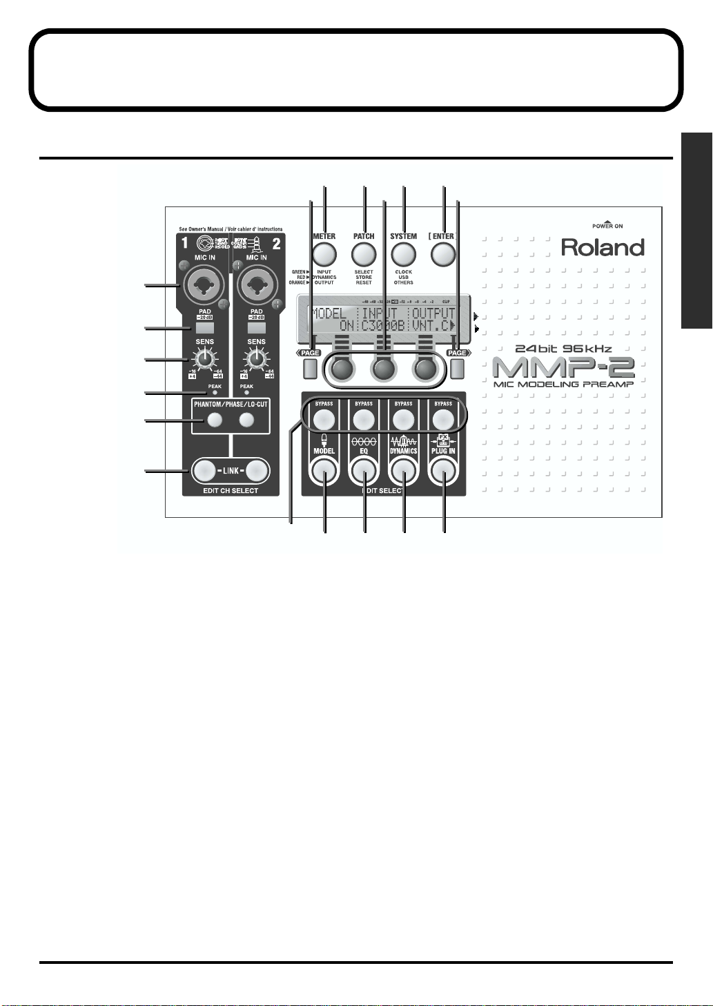
1.
[METER] Button
This changes the meter display. (p. 16)
2.
[PATCH] Button
This performs Select, Store, and Reset operations for patches. (p. 14)
3.
[SYSTEM] Button
This accesses Clock, USB, and other functions. (“Sampling Clock Source” (p. 26), “MMP-2 settings” (p. 30))
You can also adjust the contrast of the LCD screen by holding down [SYSTEM] and turning the right
Value control. (p. 14)
4.
[ENTER] Button
This confirms operations.
You also use this when you want to save a change right away. (“Save pressing [ENTER] button” (p. 14))
5.
[PAGE] Buttons
These scroll the screen a page at a time.
6.
Value Controls
These edit parameter values. The items shown on the display correspond to the controls below the screen.
These are the left, center, and right Value controls.
7.
[MIC IN] Jacks
These are balanced XLR/phone input jacks. (p. 13)
8.
[PAD] Switches
Pressing one of these attenuates the signal input to the corresponding MIC IN jack by 20 dB. (p. 17)
9.
[SENS] Controls
15
15
6
6
16
16
3
3
4
4
17
17
5
5
Top and Rear Panels
9
Top and Rear Panels
These adjust the [MIC IN] sensitivity. (p. 17)
10.
[PEAK] Indicators
These light up when the input level exceeds the set value. (p. 17)
11.
[PHANTOM/PHASE/LO-CUT] Buttons
These call up the Phantom power switches, plus the Phase, Lo-cut, and Attenuator setting screens. (p. 17)
12.
[EDIT CH SELECT] Buttons
These specify the channels to manipulate. Pressing them simultaneously links the effect settings for both
channels. (“Linking” (p. 28)).
13.
[BYPASS] Buttons
These bypass effects temporarily. (p. 19)
14.
[EDIT SELECT] Buttons ([MODEL] Button)
This calls up the editing screen for microphone modeling. (p. 19)
15.
[EDIT SELECT] Buttons ([EQ] Button)
This calls up the parameter screen for the equalizer. (p. 20)
16.
[EDIT SELECT] Buttons ([DYNAMICS] Button)
This calls up the parameter screen for dynamic effects. (p. 21)
17.
[EDIT SELECT] Buttons ([PLUG IN] Button)
This calls up the editing screen for plug-in effects. (p. 24)
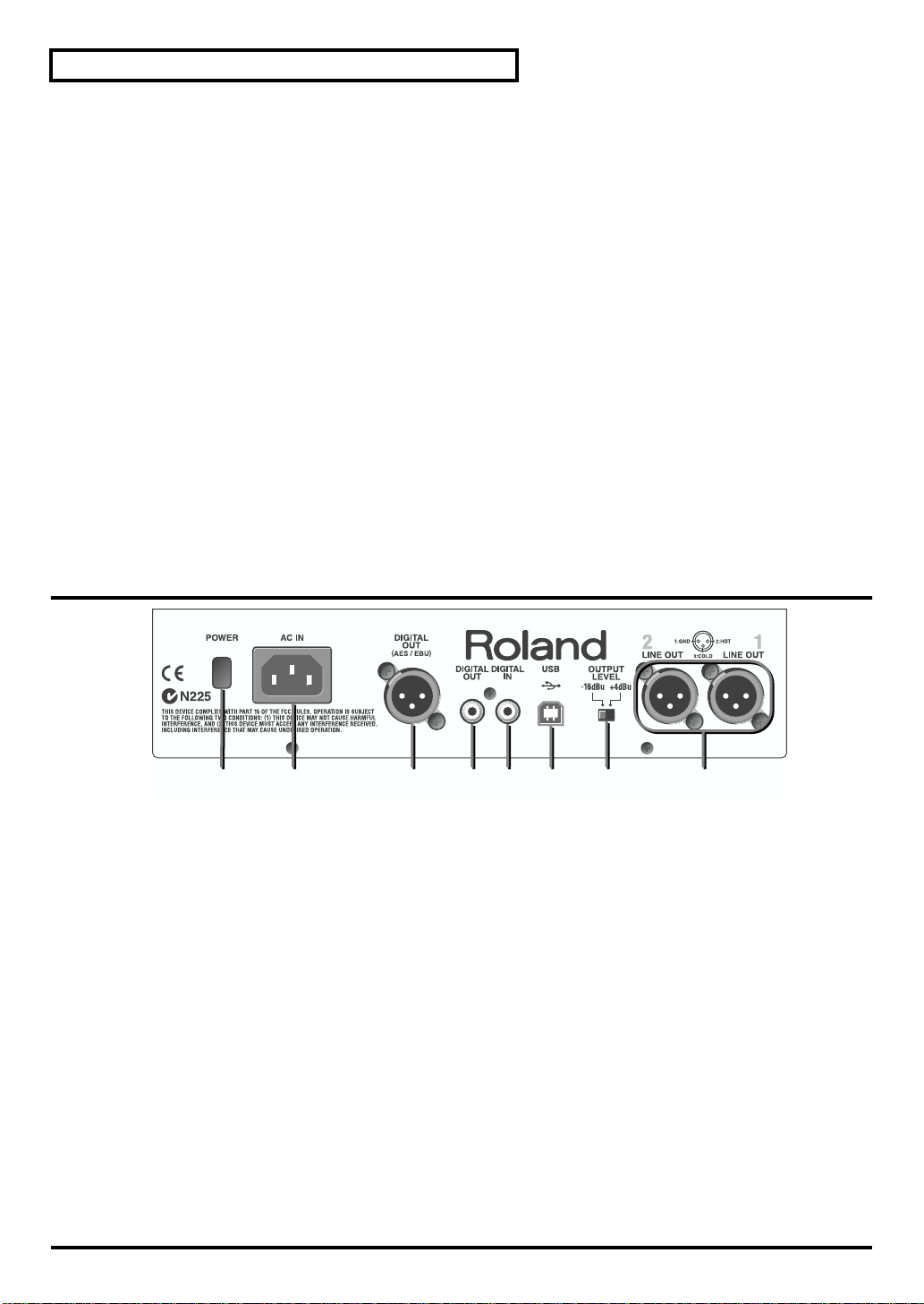
Rear Panel
10
12 34 67 85
12 34 67 85
1.
[POWER] Switch
This switches the power on and off. (p. 13)
2.
[AC IN] Connector
This is for connecting the power cable. (p. 12)
3.
[DIGITAL OUT AES/EBU] Jack
This is an AES/EBU-standard digital-output jack.
4.
[DIGITAL OUT] Jack
This is an S/PDIF-standard digital-output jack.
5.
[DIGITAL IN] Jack
This is an S/PDIF-standard digital-input jack.
6.
[USB] Jack
This is for connecting a computer and exchanging parameter settings using MIDI protocol. (p. 30)
7.
[OUTPUT LEVEL] Switch
This switches the output level to either -16 dBu or +4 dBu. (p. 13)
8.
[LINE OUT] Jack
This is a balanced XLR-type line-output jack. (p. 13)
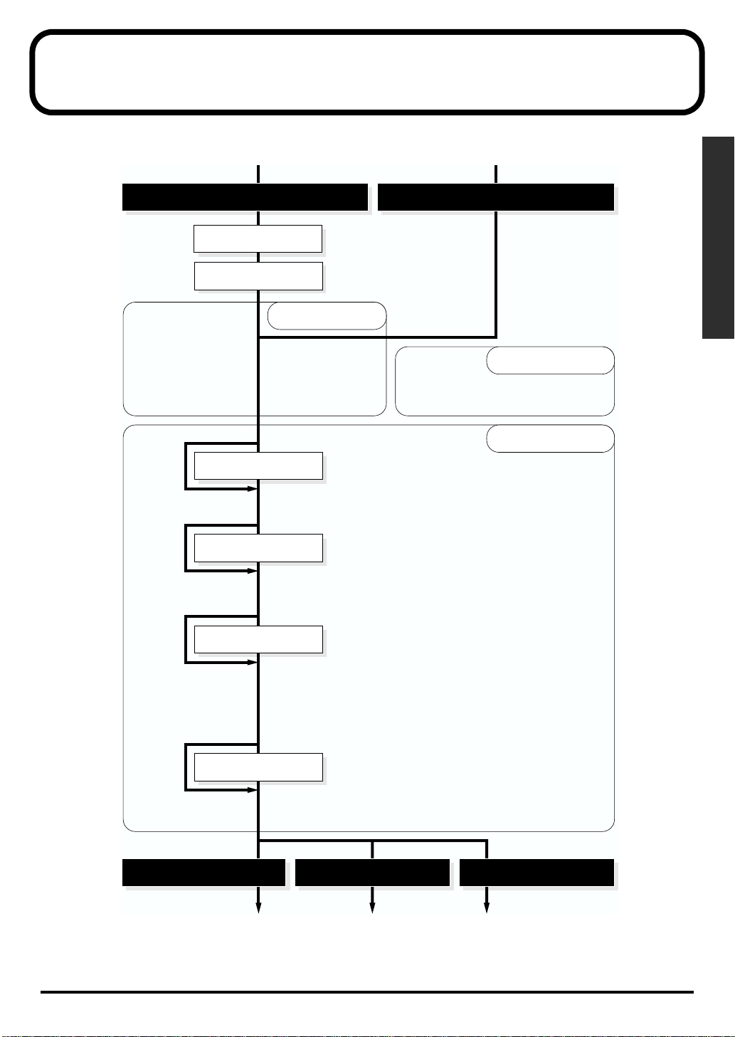
Function Organization and Signal Flow
The diagram below shows how the functions are organized, and how the signals flow.
fig.e.stract-flow.eps
balanced XLR/phone
S/PDIF
pad
sens
phantom
low cut
attenuater
bypass
bypass
phase
mic modeling
equalizer
input parameter
• off/on
• input
• output
• proximity effect
• time
• off/on
• attenuater
• frequency
• gain
• Q
• type
• LCD contrast
• peak indicate level
• sampling clock source
system parameter
• sampling frequency
• input source
• USB driver
effects parameter
Function Organization and Signal Flow
bypass
bypass
balanced XLR
dynamics
plug in
compresser
• off/on
• type
• key in
• threshold
• ratio
• knee
• attack
• release
• level
• auto-gain
expander
• off/on
• key in
• threshold
• ratio
• attack
• release
pre-amp modeling
• off/on
• type
• warm
• bright
• harmonic
enhanser/de-esser
• off/enh/des
• frequency
• sensitivity
• enhance level
• rejection level
S/PDIFAES/EBU
11
Set Up and Basic Operations
This chapter introduces the basic functions of the MMP-2 in the following order, which you should follow
in getting started with your new unit.
Getting Ready
to Switch on the Power
Read through this in sequence as you try things out for yourself.
Getting Ready to Switch on the Power
■
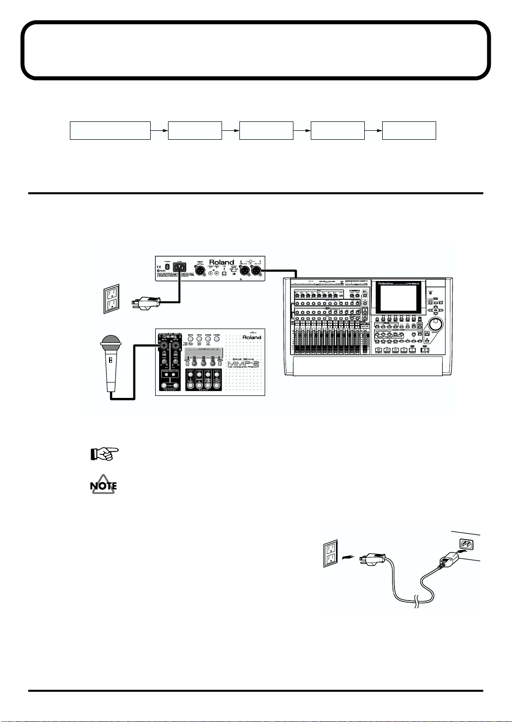
Making the Connections
fig.e.BasicConnect.eps
Switching on
the power
MMP-2
Global
Functions
Adjusting
the Input
Switching off
the power
power
recorder
microphone MMP-2
Refer to the figures and the following explanation to connect the equipment you’re using.
For information about digital connections, please read “Settings for Digital Connections” (p. 26).
To prevent problems, including malfunction and damage to speakers, turn the volume down
completely and turn off the power for all the devices being connected before making the
connections.
fig.e.PowerConnect.eps
Connecting the Power Source
Use the included power cable to connect the unit with a power
source.
MMP-2
rear panel
12
power cable
Connecting the Input Device
Microphone Input (MIC IN)
Use the XLR or phone plug to connect the input device.
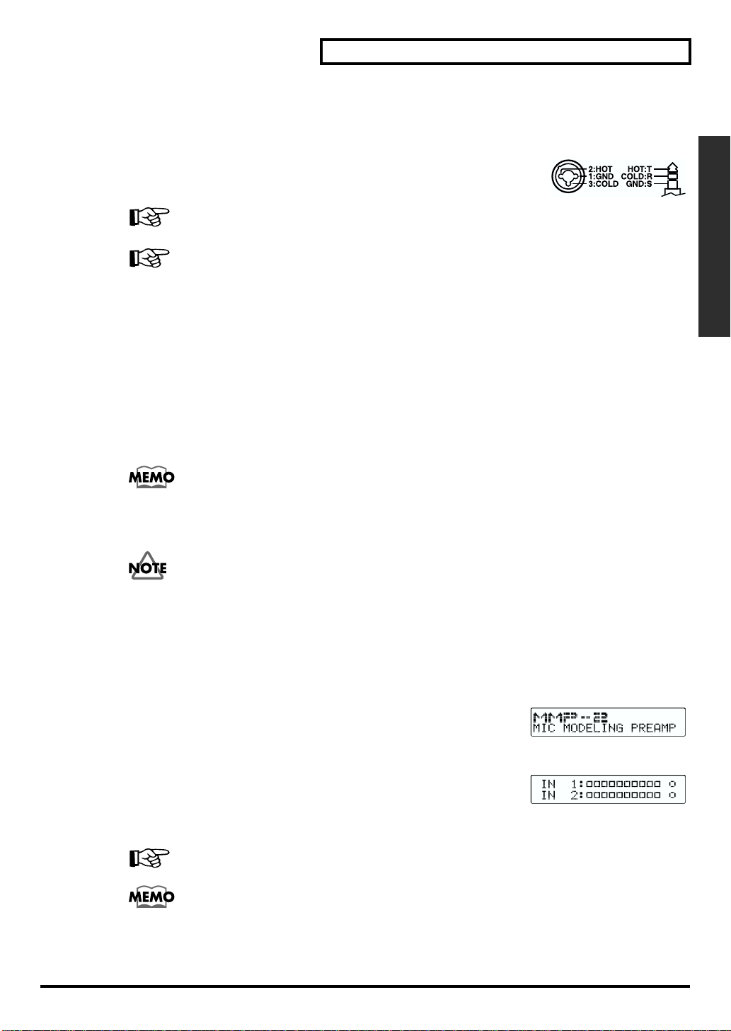
fig.MicInPin.eps
* Microphone input for the unit uses a balanced-type (XLR/TRS) jack which is wired as
shown in the figure. Check the wiring of the device you want to connect and make the
connection.
Depending on the specifications of the input device, the phase of the sound may be inverted,
resulting in input that is not correct. If this happens, refer to “Phase” (p. 18).
If you’re connecting a microphone that requires a phantom power source, refer to “Phantom
Power (+48V)” (p. 17).
Phantom power is not suppled to phone jacks.
Connecting the Output Equipment
Line Output (LINE OUT)
Use an XLR-type plug to make the connection for output to a mixer, recorder, or the like.
■
Setting the Output Level
Select level switching [OUTPUT LEVEL] on rear panel. Level should be selected in accordance with
output destination device. This value serves as the reference for the output level.
Generally, commercial equipment is designed for +4 dBu, while consumer equipment is
designed for -16 dBu.
Set Up and Basic Operations
Set Up and Basic Operations
■
Turning On the Power
Once you’ve got everything hooked up properly, you can turn on the power—but make sure
to follow the order shown below. Should you neglect to follow the correct order, you risk
causing malfunction, or damage to your speakers.
* To protect its circuitry, the unit requires a few moments after power is switched on before it is ready for normal
operation.
1.
Make sure all devices are turned off.
2.
Make sure the volume level on all equipment is turned down.
fig.LcdOpeningLogo.eps
3.
Press the Power switch (POWER) on the rear panel. When the unit starts
normally, the display shows the model name, then changes to the
Patch-selection screen. (If you perform no operation after that, the screen then
changes to the input meter.)
fig.LcdInputMeter.eps
4.
Turn on the other audio equipment.
5.
Turn up the volume to an appropriate level on the other audio equipment.
• Now sound can be produced.
For information on how to turn off the power, please read “Turning Off the Power” (p. 18).
The positioning of the microphone and speakers may produce feedback whine. If this
happens, try using the methods below to correct the problem.
• Change the direction of the microphone.
• Move the microphone and speakers farther apart.
• Lower the volume level.
13
Set Up and Basic Operations
Global Functions
In this manual, parameter settings are grouped into three categories with the following names.
System Parameters
These manipulate global settings for the entire MMP-2: CLOCK, FREQ, INPUT, DRIVER, LCDCNT, and PEAK.
Input Parameters
These manipulate basic settings for the microphone pre-amp: PHANTOM, PHASE, LO-CUT, and ATT.
Effect Parameters
These manipulate settings for microphone modeling, the equalizer, and the like: all of the settings are
called up using the [EDIT SELECT] buttons MODEL, EQ, DYNAMICS, and PLUG IN.
Save pressing [ENTER] button
When you change system parameters or input parameters, the [ENTER] button lights up. This indicates
that there are changes that have not been saved. Pressing the [ENTER] button saves them immediately.
Settings are also saved automatically whenever you change to another screen.
* If you turn off the power without saving first, any changes you have made disappear and are no longer applied.
■
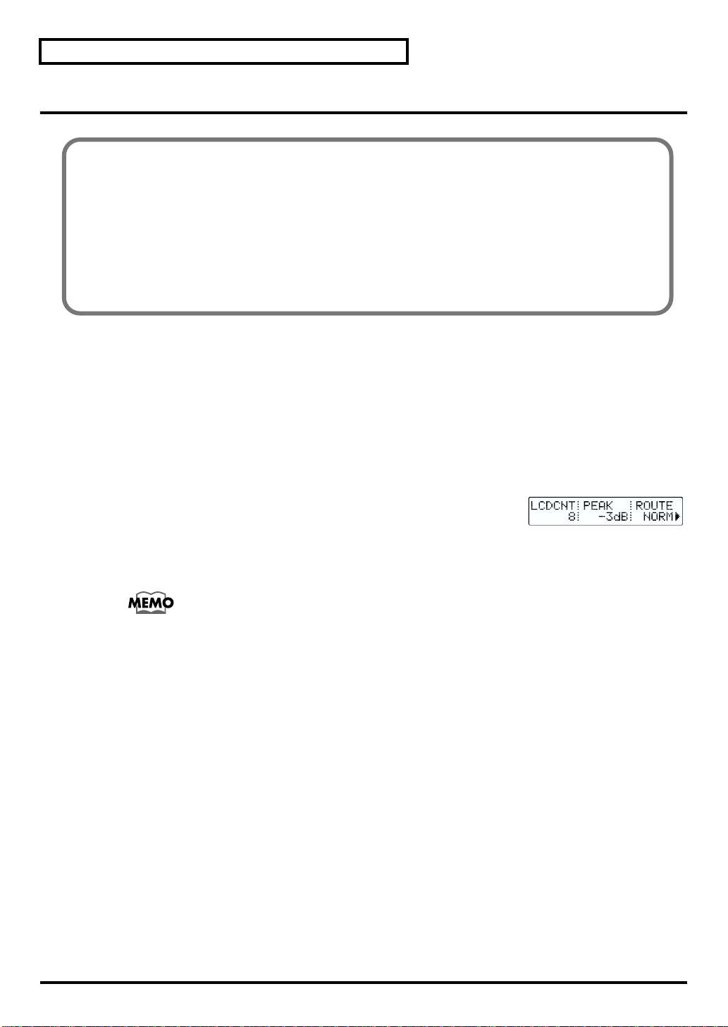
Adjusting the Contrast of the LCD Screen (LCDCNT)
fig.LcdLcdcntPeak.eps
1.
Press the [SYSTEM] button a number of times, until it lights in orange.
2.
If the screen doesn’t show the letters “LCDCNT”, use the [PAGE] buttons to
scroll to the correct page. The setting screen for LCD screen contrast appears.
3.
Turn the left Value control to make adjustments.
You can also adjust this by holding down the [SYSTEM] button and turning the right Value
control.
■
Patches
You can call up and use any of a variety of grouped settings (Patches) suited to different uses and
environments that are stored in memory. You can also take settings you’ve made yourself and save them
as patches. Settings for the presence or absence of links and effect parameters can also be saved as
patches. (“Linking” (p. 28)).
When you turn on the power, the patch you used before turning off is called up.
The functional algorithms are pre-set according to the types of patches. Each patch includes the setting of
algorithms. Users cannot control such algorithms. The [EDIT SELECT] button of each effect lights to show
that the effect is available in this patch.
Operation of patch shall be like below.
1.
Select original patch (“Patch Selection (SELECT)” (p. 15))
2.
Customize the patch changing Effect or Link parameters (“Using Effects” (p. 19)/ “Linking” (p. 28))
14
3.
Save the customized status as a new patch or overwrite (“Saving a Patch (STORE PATCH)” (p. 15))
Set Up and Basic Operations
Patch Selection (SELECT)
The alphabet character shown upper left side of the patch number is showing the status of patch.
(U) to be indicated if it is a user patch. (P) to be indicated if it is a preset patch.
You cannot customize the preset patch. But it is possible to customize the parameter of preset patch and
save as a new user patch.
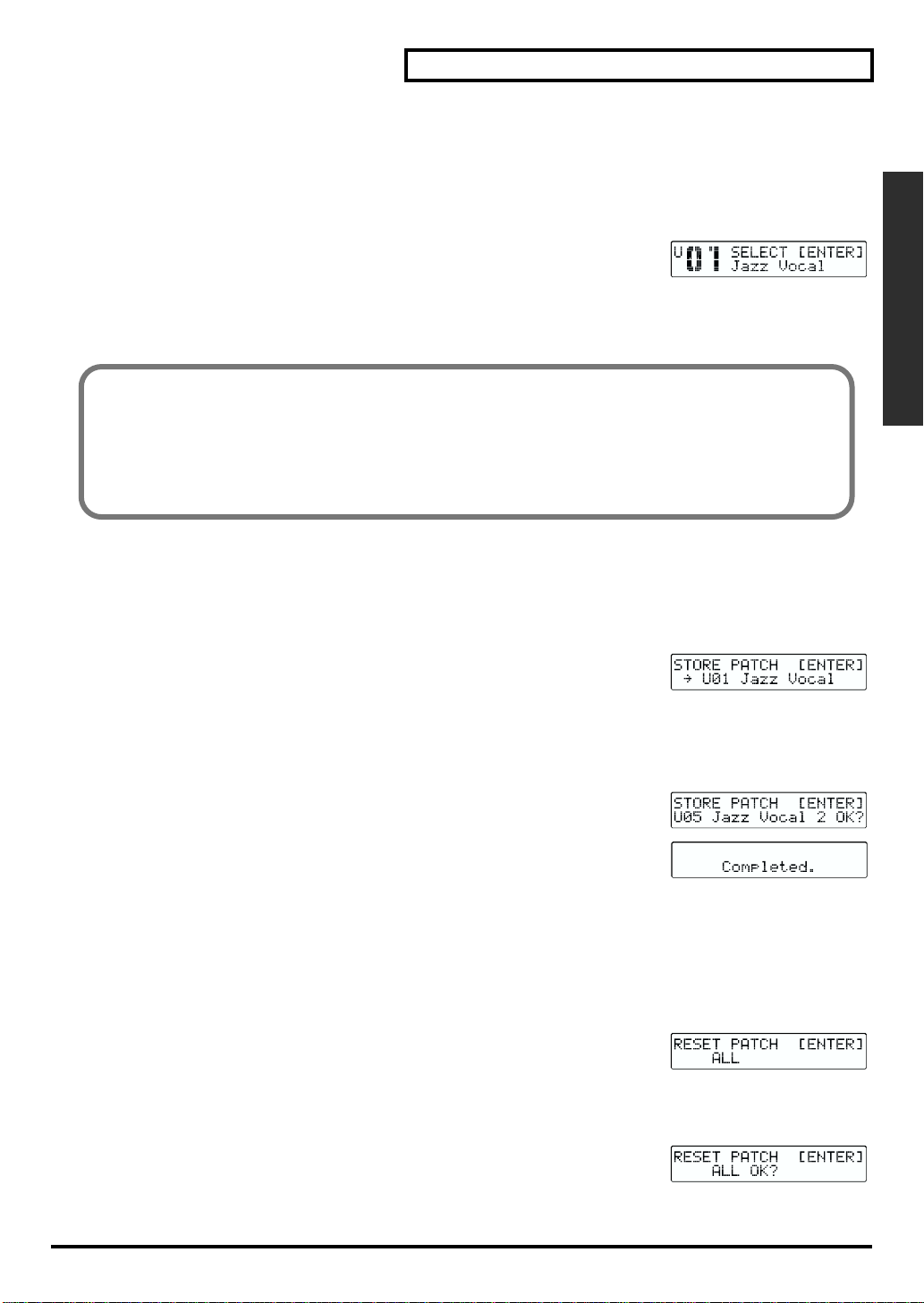
fig.LcdPatchSelect.eps
1.
Press the [PATCH] button a number of times, until it lights in green. You are
now in the mode where you can choose a patch.
2.
Turn the left Value control to choose a patch.
3.
Press the [ENTER] button to confirm your selection.
The patch currently selected will be shown at first in patch selection screen. If you turn around the knob,
the status changes and let you select other patch. You will see the currently selected patch while turning
around the knob. This to show the patch in saved status.
For example, once you select patch A and customize parameters, it is different from saved status of patch
A. However, it isn't saved yet. If you turn around the knob and re-select patch A, the parameter before
your customize will be shown.
Saving a Patch (STORE PATCH)
Save current status as a new user patch
* The patch stored in the memory area disappears and to be replaced by newly created patch.
* Only the user patch area will be shown as memory area.
fig.LcdStorePatch.eps
1.
Press the [PATCH] button a number of times, until it lights in red. You are now
in the mode where you can choose the destination for saving.
Set Up and Basic Operations
2.
Turn the left Value control to choose the patch to serve as the destination for saving.
3.
Use the center Value control to move the cursor, and use the right Value control to choose characters.
Repeat this to enter the patch name.
4.
Press [ENTER]. Your confirmation will be requested.
5.
Re-press [ENTER]. The patch will be saved. Once the saving procedure is
completed, system go back to normal screen after indicating [Completed] on
screen.
Resetting Effect Parameters (RESET)
This resets the effect parameter to the values shown below. This is the status with almost no effect. If you
want to set effect parameter completely from zero, this shall be executed. You can apply this to all effects
or to just one.
fig.LcdResetPatch.eps
1.
Press the [PATCH] button several times to display “RESET PATCH.” The button
lights up in orange.
2.
Use the left Value control to choose the target effect or effects for the [RESET] operation. Choosing “ALL”
resets all effects.
3.
Press [ENTER]. Your confirmation will be requested.
15
Set Up and Basic Operations
4.
Re-press [ENTER]. Reset will be executed. Once the reset is completed, system
go back to normal screen after indicating “Completed.” on screen.
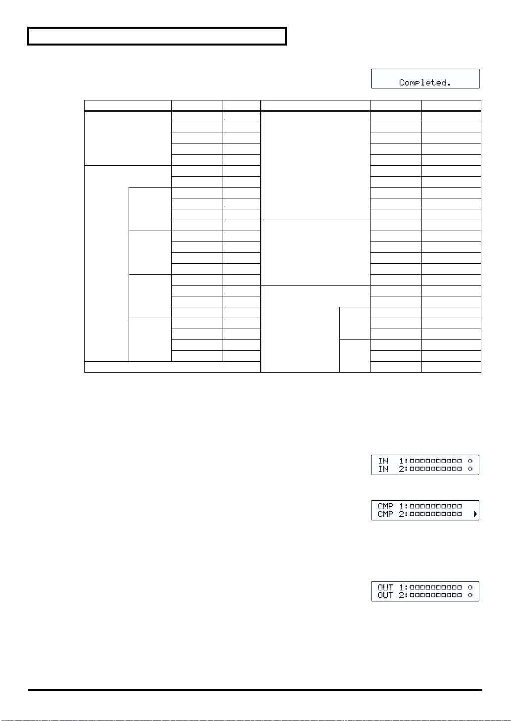
Effect Parameter Value Effect Parameter Value
mic modeling MODEL OFF compressor COMP OFF
equalizer EQ ON KNEE HARD
LOW
LO-MID
HI-MID
HIGH
INPUT C3000B TYPE SOLID
OUTPUT SML.D KEYIN same channel
PROXFX 0 THRESH -24.0
TIME 0 RATIO 2.00:1
ATT 0 ATTACK 10.0
LOTYPE PEAK RELEAS 500
LOW 80 LEVEL 0.0
GAIN 0.0 A.GAIN OFF
Q 2.00 expander EXP OFF
LMTYPE PEAK KEYIN same channel
LO-MID 400 THRESH -40
GAIN 0.0 RATIO 2.00:1
Q 2.00 ATTACK 0.0
HMTYPE PEAK RELEAS 500
HI-MID 2.00k enhancer/de-esser ENH/DE OFF
GAIN 0.0 TYPE ENH
Q 2.00
HITYPE PEAK FREQ 10.0k
HIGH 10.0k ENHLEV 6,0
GAIN 0.0
Q 2.00 FREQ 10.0k
ENH
DES
SENS 25
SENS 25
DESREJ -6.0
■
Meters
Press the [METER] button to select from the three types of level meters.
Input (IN)
fig.LcdInputMeter.eps
This displays the input level. The [METER] button lights up in green.
Dynamics (CMP / EXP)
fig.LcdDynamicsMeter.eps
This displays the level suppressed by the dynamics processors (gain reduction).
The [METER] button lights up in red.
Pressing the [PAGE] buttons switches what is displayed between the
compressor and the expander.
Output (OUT)
fig.LcdOutputMeter.eps
This displays the output level. The [METER] button lights up in orange.
■ Edit Channel Select (EDIT CH SELECT)
These choose the channel to edit. Pressing an [EDIT CH SELECT] button makes the button light up green,
showing that the corresponding channel is selected. You make the settings for effects one channel at a time.
The system enters Link Mode pressing channel 2 button holding down channel 1 button. (“Linking” (p. 28))
16
Settings for the Analog Inputs
■ Pad
Pressing either of these switches attenuates the MIC IN input signal by 20 dB. You use these at times such
as when devices other than microphones are connected. Press them again to cancel.
■ Sensitivity (SENS)
These adjust the input sensitivity. You can perform adjustments within a range of -64 dBu to -16 dBu
(within a range of -44 dBu to +4 dBu when PAD is depressed).
When a microphone input has nothing connected to it, it may be a good idea to press the
PAD switch and leave the SENS control set at +4 dBu. This suppresses the amount of noise
sent to the unit.
■ Peak Indicator
The peak indicator lights up when the input level from microphone input jacks exceeds the value set for PEAK.
At the factory default setting, it lights up at -3 dBu. To change this, follow the steps below.
fig.LcdLcdcntPeak.eps
1. Press the [SYSTEM] button several times to display “PEAK.” The button lights
up in orange.
2. Turn the center Value control to change the settings.
“ 0 dB”: The indicator lights up when the input sound is distorted.
“-3 dB”: The indicator Lights up at -3 dB from the level at which sound will distort.
“-6 dB”: Lights up at -6 dB from the sound-distortion level.
Set Up and Basic Operations
Set Up and Basic Operations
■ Phantom Power (+48V)
These switch the phantom power supply on and off. When a condenser microphone or other microphone
that requires a power source is connected to the corresponding MIC IN jack, set this to “ON.”
Phantom power is not supplied to 1/4 inch TRS phone jacks. If your microphone requires
phantom power, please connect it to XLR jacks.
Turn this on only when a condenser microphone requiring a phantom power source is
connected. Otherwise, leave it off. Supplying phantom power to a dynamic microphone or
audio playback equipment may cause malfunction, so carefully check the documentation for
the connected device and make the setting accordingly. (The spec for the phantom power
source for this unit is DC 48 V and 7 mA when the output is shorted.)
The phantom power source of MMP-2 can drive Condenser Microphones with electrical
specification 6.0mA or lower at 48V. Microphones that require more ampere is not
supported. Please use phantom power supply devices separately.
To prevent hazard or damage, ensure that only microphone cables and microphones designed to
IEC-268-15A are connected.
Afin d’eviter tout risque ou dommage, ne brancher que des cables de microphone et des
microphones conformes a la norme IEC-268-15A.
* The unit is designed not to produce noise when switching the phantom setting, but just to be on the safe side,
turn down the volume level before switching the setting.
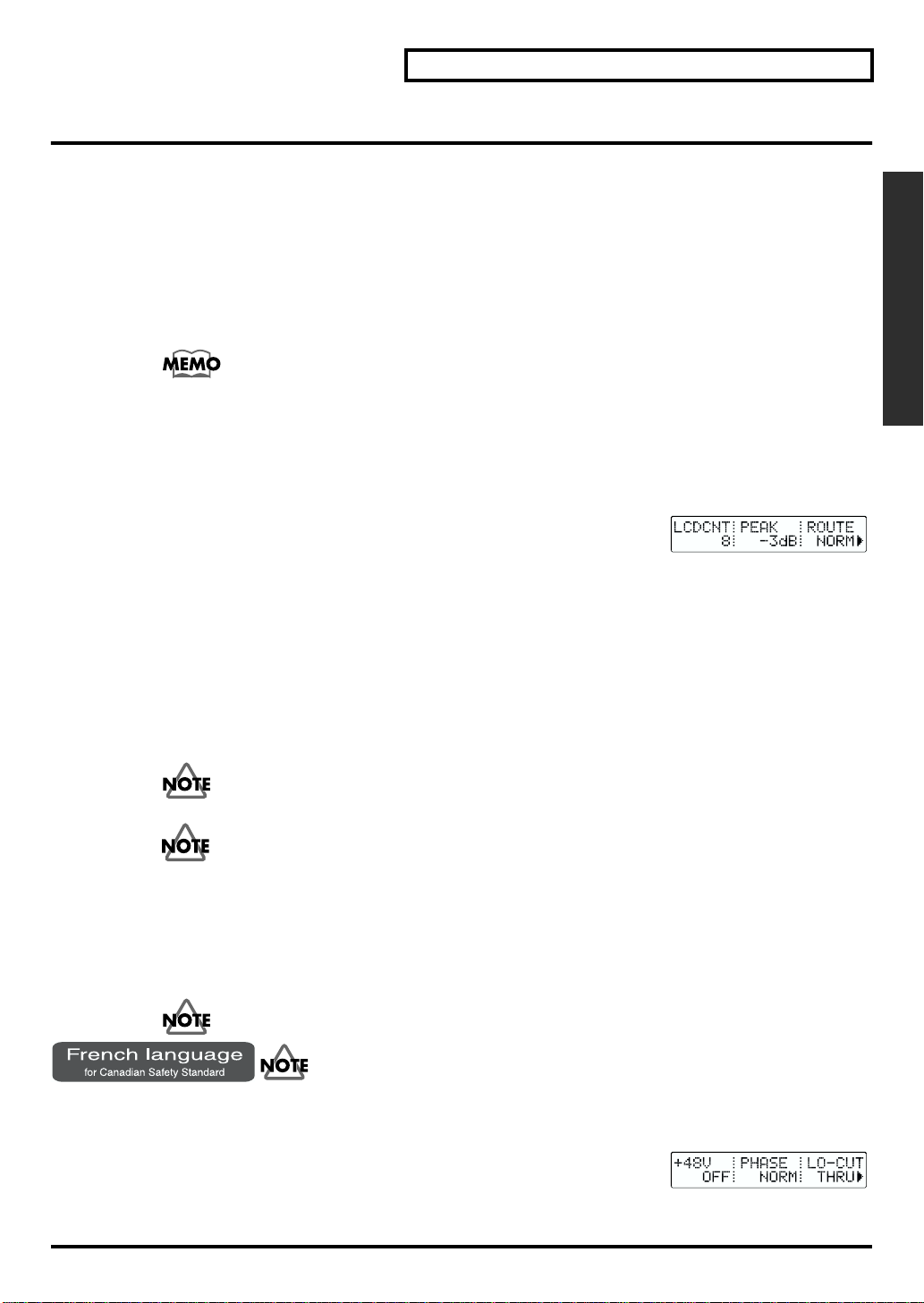
fig.LcdPhantomPhaseLocut.eps
1. Press the [PHANTOM,PHASE,LO-CUT] button to display “+48V.”
2. Use the left Value control to switch between “ON” and “OFF.”
3. Press the [ENTER] button to confirm your selection.
17
Set Up and Basic Operations
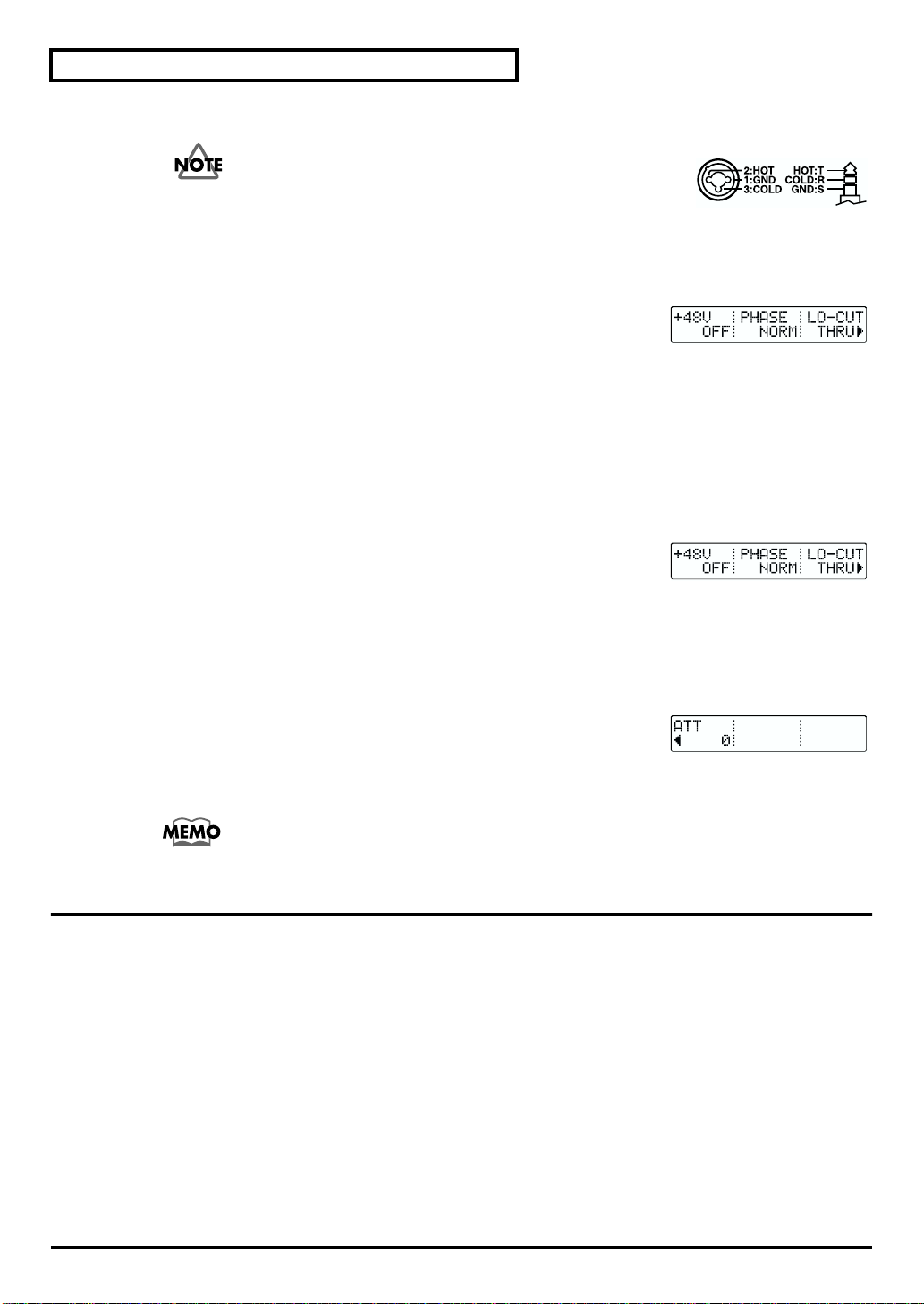
■ Phase
fig.MicInPin.eps
The microphone input jacks for this unit are balanced. The jack wiring
is shown in the figure. However, Hot and Cold may be reversed of
MMP-2 on some balanced equipment. If such equipment is connected,
sound localization may be poor, or the balance of left and right will be
disrupted. Furthermore, the left and right channels may cancel each other when stereo input
is used. The phase shall be set same as MMP-2 in all channels before the use.
* If the phase is same through out all channels, it causes no problem even in case the wiring is different from mixers etc.
fig.LcdPhantomPhaseLocut.eps
1. Press the [PHANTOM,PHASE,LO-CUT] button.
2. Turn the center Value control to switch “PHASE” between “NORM” and “INV.”
“NORM” (normal): Normal phase (same phase as input).
“INV” (invert): Inverted (opposite) phase.
* Usually “NORM” is selected.
■ Low-cut Filter (LO-CUT)
This cuts the audio below a specified frequency. This is effective when you want to eliminate bass noise such
as microphone stand rumble or microphone handling noise. You can set a value from 20 dB to 2.00k dB.
fig.LcdPhantomPhaseLocut.eps
1. Press the [PHANTOM,PHASE,LO-CUT] button.
2. Turn the right Value control to specify the threshold frequency for cutoff. When
set to “THRU,” the original signal is passed without performing low-band cutoff.
■ Attenuator (ATT)
This adjusts the level of the input signal using digital processing. You can set a value from -42 dB to +6 dB.
fig.LcdAttenuater.eps
1. Press the [PHANTOM,PHASE,LO-CUT] button.
2. Press the [PAGE] buttons to advance the screen until “ATT” appears.
3. Turn the left Value control to set the value.
Leaving the attenuator set at 0 dB and adjusting for the optimal audio levels using only the
Sensitivity (SENS) control may result in the best possible audio in most cases.
Turning Off the Power
* If you’ve changed any effect parameters, you should note that your changes will be lost if you turn off the power
before they’ve been saved. If you want to keep your settings, save them in a patch (p. 15).
* Similarly, with system parameters, any setting changes you’ve made, but have not saved will be discarded as
soon as you turn off the power. If you want to keep your settings, press the [ENTER] button to save them (p. 14).
1. Lower the volume on the other audio equipment.
2. Turn off the other audio equipment.
3. Use the [POWER] switch on the rear panel to turn off the MMP-2.
18

Using Effects
The effects this unit provides are divided into four groups, which are respectively assigned to the four
[EDIT SELECT] buttons [MODEL], [EQ], [DYNAMICS], and [PLUG IN].
The functional algorithms are pre-set according to the types of patches (p. 14). Each patch includes the
setting of algorithms. Users cannot control such algorithms. The [EDIT SELECT] button of each effect
lights to show that the effect is available in this patch.
If you press [EDIT SELECT] buttons of effects that are not functioning, “Can’t edit. No effects module.”
will be displayed.
The steps for effect operations are as follows.
1. Press the [EDIT CH SELECT] button to select the channel you want to work on.
2. Press the [EDIT SELECT] button to select the effect you want to manipulate.
3. If the screen for the parameter you want to change for does not appear, use the [PAGE] buttons to scroll
through the screens.
* While adjusting some parameters such as effect “TYPE”, you may hear short click noise. This is not a malfunction.
You can call up and use any of a variety of grouped settings (Patches) suited to different uses
and environments that are stored in memory. You can also save settings you have changed
as patches. (“Patches” (p. 14))
BYPASS
This has the same effect as setting the Effect ON/OFF parameter to OFF. (However, the setting for the
ON/OFF parameter does not change.) The Dynamics settings have a number of switches, and they are all
bypassed at one time.
Pressing the [BYPASS] button makes the button light up red, and in this state effects are bypassed. Press
again to cancel.
Using Effects
Mic Modeling
This effect models the sound characteristics of certain types of expensive microphones. It works best
when the input source you use matches the settings available in the processor. For example, the effect is
optimized if you use an AKG C3000B or a Roland DR-20 microphone as the source microphone and then
choose the output microphone whose characteristics you would like to model. You can also edit the
modeling effect by changing microphone proximity or distance effects, and other qualities.
Mic Modeling OFF/ON (MODEL)
This is the On/Off switch for the microphone modeling.
Reference Microphone (INPUT)
This table shows the optimum choices for the microphones or inputs to use when using the microphone
modeling effect.
When you use modeling, specify the microphone used when making the recording or pick the choice
closest to the microphone you used.
DR-20 Roland DR-20 Dynamic microphone from Roland
SML.D Small Dynamic Microphone Dynamic microphone used for musical instruments and vocals
HED.D Head-worn Dynamic Microphone Headset-type dynamic microphone
MIN.C Miniature Condenser Microphone Ultra-compact condenser microphone
FLAT Flat Line in
C3000B AKG C 3000 B Condenser microphone from AKG Acoustics
19
 Loading...