

Roland Corporation GS-10 Owner's Manual

Owner’s Manual
Thank you, and congratulations on your choice of the
BOSS GS-10 Guitar Effects System with USB Audio Interface.
Before using this unit, carefully read the sections entitled:
• USING THE UNIT SAFELY (page 2–3)
• IMPORTANT NOTES (page 4–5)
These sections provide important information concerning the
proper operation of the unit.
Additionally, in order to feel assured that you have gained a
good grasp of every feature provided by your new unit, Owner’s
manual should be read in its entirety. The manual should be
saved and kept on hand as a convenient reference.
■
Printing Conventions in This Manual
• Text or numerals enclosed in square brackets [ ] indicate buttons.
[WRITE]
[USB]
WRITE button
USB button
• Reference such as (p. **) indicate pages in this manual to which you
can refer.
Copyright © 2003 BOSS CORPORATION
All rights reserved. No part of this publication may be reproduced in any form
without the written permission of BOSS CORPORATION.

USING THE UNIT SAFELY
Used for instructions intended to alert
the user to the risk of death or severe
injury should the unit be used
improperly.
Used for instructions intended to alert
the user to the risk of injury or material
damage should the unit be used
improperly.
* Material damage refers to damage or
other adverse effects caused with
respect to the home and all its
furnishings, as well to domestic
animals or pets.
001
• Before using this unit, make sure to read the
instructions below, and the Owner’s Manual.
..........................................................................................................
002c
• Do not open (or modify in any way) the unit or its
AC adaptor.
..........................................................................................................
003
• Do not attempt to repair the unit, or replace parts
within it (except when this manual provides
specific instructions directing you to do so). Refer
all servicing to your retailer, the nearest Roland
Service Center, or an authorized Roland
distributor, as listed on the “Information” sheet.
..........................................................................................................
004
• Never use or store the unit in places that are:
• Subject to temperature extremes (e.g., direct
sunlight in an enclosed vehicle, near a heating
duct, on top of heat-generating equipment); or
are
• Damp (e.g., baths, washrooms, on wet floors);
or are
• Humid; or are
• Exposed to rain; or are
• Dusty; or are
• Subject to high levels of vibration.
..........................................................................................................
007
• Make sure you always have the unit placed so it is
level and sure to remain stable. Never place it on
stands that could wobble, or on inclined surfaces.
..........................................................................................................
008c
• Be sure to use only the AC adaptor supplied with
the unit. Also, make sure the line voltage at the
installation matches the input voltage specified on
the AC adaptor’s body. Other AC adaptors may
use a different polarity, or be designed for a
different voltage, so their use could result in
damage, malfunction, or electric shock.
..........................................................................................................
The symbol alerts the user to important instructions
or warnings.The specific meaning of the symbol is
determined by the design contained within the
triangle. In the case of the symbol at left, it is used for
general cautions, warnings, or alerts to danger.
The symbol alerts the user to items that must never
be carried out (are forbidden). The specific thing that
must not be done is indicated by the design contained
within the circle. In the case of the symbol at left, it
means that the unit must never be disassembled.
The ● symbol alerts the user to things that must be
carried out. The specific thing that must be done is
indicated by the design contained within the circle. In
the case of the symbol at left, it means that the powercord plug must be unplugged from the outlet.
009
• Do not excessively twist or bend the power cord,
nor place heavy objects on it. Doing so can
damage the cord, producing severed elements and
short circuits. Damaged cords are fire and shock
hazards!
..........................................................................................................
010
• This unit, either alone or in combination with an
amplifier and headphones or speakers, may be
capable of producing sound levels that could
cause permanent hearing loss. Do not operate for
a long period of time at a high volume level, or at
a level that is uncomfortable. If you experience
any hearing loss or ringing in the ears, you should
immediately stop using the unit, and consult an
audiologist.
..........................................................................................................
011
• Do not allow any objects (e.g., flammable material,
coins, pins); or liquids of any kind (water, soft
drinks, etc.) to penetrate the unit.
..........................................................................................................
012b
• Immediately turn the power off, remove the AC
adaptor from the outlet, and request servicing by
your retailer, the nearest Roland Service Center, or
an authorized Roland distributor, as listed on the
“Information” sheet when:
• The AC adaptor, the power-supply cord, or the
plug has been damaged; or
• If smoke or unusual odor occurs
• Objects have fallen into, or liquid has been
spilled onto the unit; or
• The unit has been exposed to rain (or otherwise
has become wet); or
• The unit does not appear to operate normally or
exhibits a marked change in performance.
..........................................................................................................
2

013
• In households with small children, an adult
should provide supervision until the child is
capable of following all the rules essential for the
safe operation of the unit.
..........................................................................................................
014
• Protect the unit from strong impact.
(Do not drop it!)
..........................................................................................................
015
• Do not force the unit’s power-supply cord to share
an outlet with an unreasonable number of other
devices. Be especially careful when using
extension cords—the total power used by all
devices you have connected to the extension
cord’s outlet must never exceed the power rating
(watts/amperes) for the extension cord. Excessive
loads can cause the insulation on the cord to heat
up and eventually melt through.
..........................................................................................................
016
• Before using the unit in a foreign country, consult
with your retailer, the nearest Roland Service
Center, or an authorized Roland distributor, as
listed on the “Information” sheet.
..........................................................................................................
023
• DO NOT play a CD-ROM disc on a conventional
audio CD player. The resulting sound may be of a
level that could cause permanent hearing loss.
Damage to speakers or other system components
may result.
..........................................................................................................
101b
• The unit and the AC adaptor should be located so
their location or position does not interfere with
their proper ventilation.
..........................................................................................................
102c
• Always grasp only the plug on the AC adaptor
cord when plugging into, or unplugging from, an
outlet or this unit.
..........................................................................................................
103b
• At regular intervals, you should unplug the AC
adaptor and clean it by using a dry cloth to wipe
all dust and other accumulations away from its
prongs. Also, disconnect the power plug from the
power outlet whenever the unit is to remain
unused for an extended period of time. Any
accumulation of dust between the power plug and
the power outlet can result in poor insulation and
lead to fire.
..........................................................................................................
104
• Try to prevent cords and cables from becoming
entangled. Also, all cords and cables should be
placed so they are out of the reach of children.
..........................................................................................................
106
• Never climb on top of, nor place heavy objects on
the unit.
..........................................................................................................
107c
• Never handle the AC adaptor or its plugs with
wet hands when plugging into, or unplugging
from, an outlet or this unit.
..........................................................................................................
108b
• Before moving the unit, disconnect the AC
adaptor and all cords coming from external
devices.
..........................................................................................................
109b
• Before cleaning the unit, turn off the power and
unplug the AC adaptor from the outlet.
..........................................................................................................
110b
• Whenever you suspect the possibility of lightning
in your area, disconnect the AC adaptor from the
outlet.
..........................................................................................................
3

IMPORTANT NOTES
291a
In addition to the items listed under “USING THE UNIT SAFELY” on page 2–3, please read and observe the following:
Power Supply
301
• Do not use this unit on the same power circuit with any
device that will generate line noise (such as an electric
motor or variable lighting system).
302
• The AC adaptor will begin to generate heat after long
hours of consecutive use. This is normal, and is not a
cause for concern.
307
• Before connecting this unit to other devices, turn off the
power to all units. This will help prevent malfunctions
and/or damage to speakers or other devices.
Placement
351
• Using the unit near power amplifiers (or other equipment
containing large power transformers) may induce hum.
To alleviate the problem, change the orientation of this
unit; or move it farther away from the source of interference.
352a
• This device may interfere with radio and television
reception. Do not use this device in the vicinity of such
receivers.
352b
• Noise may be produced if wireless communications
devices, such as cell phones, are operated in the vicinity of
this unit. Such noise could occur when receiving or initiating a call, or while conversing. Should you experience
such problems, you should relocate such wireless devices
so they are at a greater distance from this unit, or switch
them off.
354a
• Do not expose the unit to direct sunlight, place it near
devices that radiate heat, leave it inside an enclosed
vehicle, or otherwise subject it to temperature extremes.
Excessive heat can deform or discolor the unit.
355b
• When moved from one location to another where the
temperature and/or humidity is very different, water
droplets (condensation) may form inside the unit. Damage
or malfunction may result if you attempt to use the unit in
this condition. Therefore, before using the unit, you must
allow it to stand for several hours, until the condensation
has completely evaporated.
Maintenance
401a
• For everyday cleaning wipe the unit with a soft, dry cloth
or one that has been slightly dampened with water. To
remove stubborn dirt, use a cloth impregnated with a
mild, non-abrasive detergent. Afterwards, be sure to wipe
the unit thoroughly with a soft, dry cloth.
402
• Never use benzine, thinners, alcohol or solvents of any
kind, to avoid the possibility of discoloration and/or
deformation.
Repairs and Data
452
• Please be aware that all data contained in the unit’s
memory may be lost when the unit is sent for repairs.
Important data should always be backed up in another
MIDI device (e.g., a sequencer), computer, or written
down on paper (when possible). During repairs, due care
is taken to avoid the loss of data. However, in certain
cases (such as when circuitry related to memory itself is
out of order), we regret that it may not be possible to
restore the data, and Roland assumes no liability
concerning such loss of data.
Memory Backup
501b
• This unit contains a battery which powers the unit’s
memory circuits while the main power is off. When this
battery becomes weak, the message shown below will
appear in the display. Once you see this message, have the
battery replaced with a fresh one as soon as possible to
avoid the loss of all data in memory. To have the battery
replaced, consult with your retailer, the nearest Roland
Service Center, or an authorized Roland distributor, as
listed on the “Information” sheet.
“Battery Low !! Please Change”
Additional Precautions
551
• Please be aware that the contents of memory can be
irretrievably lost as a result of a malfunction, or the
improper operation of the unit. To protect yourself against
the risk of loosing important data, we recommend that
you periodically save a backup copy of important data
you have stored in the unit’s memory in another MIDI
device (e.g., a sequencer), or computer.
552
• Unfortunately, it may be impossible to restore the contents
of data that was stored in another MIDI device (e.g., a
sequencer), or computer once it has been lost. Roland
Corporation assumes no liability concerning such loss of
data.
553
• Use a reasonable amount of care when using the unit’s
buttons, sliders, or other controls; and when using its jacks
and connectors. Rough handling can lead to malfunctions.
554
• Never strike or apply strong pressure to the display.
556
• When connecting / disconnecting all cables, grasp the
connector itself—never pull on the cable. This way you
will avoid causing shorts, or damage to the cable’s
internal elements.
558a
• To avoid disturbing your neighbors, try to keep the unit’s
volume at reasonable levels. You may prefer to use
headphones, so you do not need to be concerned about
those around you (especially when it is late at night).
4

IMPORTANT NOTES
559a
• When you need to transport the unit, package it in the box
(including padding) that it came in, if possible. Otherwise,
you will need to use equivalent packaging materials.
561
• Use only the specified expression pedal (EV-5; sold
separately). By connecting any other expression pedals,
you risk causing malfunction and/or damage to the unit.
562
• Use a cable from Roland to make the connection. If using
some other make of connection cable, please note the
following precautions.
• Some connection cables contain resistors. Do not use
cables that incorporate resistors for connecting to this
unit. The use of such cables can cause the sound level
to be extremely low, or impossible to hear. For information on cable specifications, contact the manufacturer of the cable.
Handling CD-ROMs
563
• Unauthorized duplication, reproduction, hiring, and
lending prohibited.
564
• Before you open the included CD-ROM, you must read
the “license agreement.” Opening the CD-ROM will be
taken to mean your acceptance of the license agreement.
801
• Avoid touching or scratching the shiny underside
(encoded surface) of the disc. Damaged or dirty CD-ROM
discs may not be read properly. Keep your discs clean
using a commercially available CD cleaner.
962b
• In the interest of product improvement, the specifications
and/or contents of this package are subject to change
without prior notice.
Copyright
851
• Unauthorized recording, distribution, sale, lending, public
performance, broadcasting, or the like, in whole or in part,
of a work (musical composition, video, broadcast, public
performance, or the like) whose copyright is held by a
third party is prohibited by law.
852a
• When exchanging audio signals through a digital
connection with an external instrument, this unit can
perform recording without being subject to the restrictions
of the Serial Copy Management System (SCMS). This is
because the unit is intended solely for musical production,
and is designed not to be subject to restrictions as long as
it is used to record works (such as your own compositions) that do not infringe on the copyrights of others.
(SCMS is a feature that prohibits second-generation and
later copying through a digital connection. It is built into
MD recorders and other consumer digital-audio
equipment as a copyright-protection feature.)
853
• Do not use this unit for purposes that could infringe on a
copyright held by a third party. We assume no responsibility whatsoever with regard to any infringements of
third-party copyrights arising through your use of this
unit.
• DO NOT play a CD-ROM disc on a conventional audio
CD player. The resulting sound may be of a level that
could cause permanent hearing loss. Damage to speakers
or other system components may result.
204
* Microsoft and Windows are registered trademarks of Microsoft Corporation.
206e
* Screen shots in this documents are reprinted with permission from Microsoft Corporation.
206j
* Windows® is known officially as: “Microsoft® Windows® operating system.”
207
* Apple and Macintosh are registered trademark of Apple Computer, Inc.
209
* MacOS is a trademark of Apple Computer, Inc.
220
* All product names mentioned in this document are trademarks or registered trademarks of their respective owners.
231
* OMS is a registered trademark of Opcode Systems, Inc.
232
* FreeMIDI is a trademark of Mark of the Unicorn, Inc.
5

Contents
USING THE UNIT SAFELY ...................2
IMPORTANT NOTES ..........................4
Main Features ..................................9
Panel Descriptions ..........................10
Front Panel.......................................................................10
Rear Panel........................................................................12
Signal Flow...................................................................... 13
Chapter 1
Playing Sounds ..............................14
Making the Connections...............................................14
Turning On the Power ..................................................15
Turning Off the Power..............................................15
Using the GS-10’s Speakers .........................................15
Adjusting the Output Level .........................................15
Setting Output Device (Amps)
(OUTPUT SELECT) .......................................................16
Connecting
Audio Devices to the AUX INPUT Jack.....................17
Using the Digital Output.............................................. 17
Chapter 2
Creating Your Own Favorite Tones
(Patches)
What is a Patch?..............................................................18
How to Select Patches (Patch Change).......................18
About the Display Indication ..................................18
If the Patch Does Not Switch ...................................18
Selecting the Input (INPUT SELECT)........................19
Setting the Mic Input Level (MIC GAIN) ..............20
Adjusting the Tones with the Knobs .........................21
Turning the Effect On and Off....................................22
Setting the Effects Simply (QUICK FX) ....................22
Making More Precise Effect Settings.........................23
Naming Patches..............................................................24
Changing the Connection Order of Effects
(Effect Chain) ..................................................................24
..........................................18
Chapter 3
Saving the Tones You Have Created
Storing Patches (PATCH WRITE)...............................25
Copying Patches .............................................................25
Exchanging Patches........................................................26
Initializing Patches ........................................................26
Registering Your Favorite Patches
(DIRECT PATCH)..........................................................27
Copying the PREAMP/SPEAKER Settings
to Another Channel........................................................27
.....25
Chapter 4
Introduction to Effects and Parameters
PREAMP/SPEAKER
(Preamp/Speaker Simulator)........................................28
COMP (Compressor) .....................................................31
OD/DS (Overdrive/Distortion)....................................32
DELAY..............................................................................33
CHORUS..........................................................................34
REVERB ...........................................................................34
EQ (Equalizer).................................................................35
FX-1....................................................................................36
PW (Pedal Wah).........................................................36
AW (Auto Wah).........................................................36
TM (Tone Modify) .....................................................37
ACS (Advanced Compressor)..................................38
LM (Limiter) ...............................................................38
ENH (Enhancer).........................................................39
SG (Slow Gear)...........................................................39
TR (Tremolo) ..............................................................39
DF (Defretter) .............................................................40
RM (Ring Modulator)................................................40
FB (Feedbacker)..........................................................40
FX-2....................................................................................41
PH (Phaser).................................................................42
FL (Flanger) ................................................................42
HR (Harmonist) .........................................................43
PS (Pitch Shifter) ........................................................44
OC (Octave) ................................................................45
PB (Pedal Bend)..........................................................45
2CE (2x2 Chorus) .......................................................45
PAN .............................................................................46
....28
6

Contents
VB (Vibrato)................................................................46
UV (Uni-V) .................................................................47
RT (Rotary) .................................................................47
SDD (Short Delay) .....................................................48
HU (Humanizer)........................................................48
SL (Slicer) ....................................................................49
AR (Auto Riff)............................................................49
SYN (Guitar Synth) ...................................................50
BS (Bass Simulator) ...................................................52
SEQ (Stereo Equalizer)..............................................52
NAME/NS/MASTER .....................................................53
Name (Patch Name)..................................................53
Noise Suppressor.......................................................53
Master..........................................................................54
Foot Volume...............................................................54
Effect Chain ................................................................54
Chapter 5
Creating Original Effects Types (Customize)
Customizing the COSM Amps.................................... 55
Customizing the Speakers............................................56
Customizing Overdrive and Distortion.....................56
Customizing Pedal Wah ...............................................57
..55
Chapter 6
Setting the External Pedal Functions
Setting the External Expression Pedal Functions
(Expression Pedal Function)
Setting the External Foot Switch Functions
(Control 1, 2 Function)................................................... 59
Setting the External Pedal Function
for Individual Patches (Assign)...................................60
Quick Settings ............................................................60
Manual Settings .........................................................61
..............................................58
.....58
Chapter 7
Convenient Functions and System Settings
Tuning the Guitar ..........................................................64
Turning the Tuner Function On ..............................64
About the Display During Tuning..........................64
How to Tune...............................................................64
Changing the Tuner Settings ...................................64
Adjusting the Display Contrast
(LCD Contrast)................................................................65
Limiting the Patches
That Can Be Switched (Patch Extent) .........................65
Keeping the Same Pedal Operations
When Switching Patches (Assign Hold)....................66
Setting the Knob Functions (Knob Mode) ................66
Checking the Effect Output Level
with the Level Meter......................................................67
...64
Chapter 8
Using the GS-10 with
External MIDI Devices Connected
Operations Using MIDI ................................................68
Operating From the GS-10........................................68
Remotely Controlling the GS-10
Using an External MIDI Device...............................68
Making the Settings for MIDI Functions..................69
Transmitting and Receiving Settings Data ...............71
Transmitting Data
to an External MIDI Device (Bulk Dump) .............71
Receiving Data
from an External MIDI Device (Bulk Load)...........72
Setting the Program Change Map...............................73
Enabling/Disabling the
Program Change Map Settings (MIDI Map Select)
Changing Patch Numbers
on an External MIDI Device From the GS-10 ...........74
Controlling Recorders and Sequencers Remotely
from the GS-10 (Remote Control)
Setting the Messages
Used for Controlling Devices...................................75
Controlling the Device Remotely ............................76
.....................................75
.........68
.......74
7

Contents
Chapter 9
Using the GS-10
Connected to a Computer Via USB
Before Connecting with USB.......................................78
Driver Mode ...............................................................78
Setting USB-Related Functions...................................78
Adjusting the Recording Level
(Output Level)............................................................78
Adjusting the Playback Volume Level
(Input Level)...............................................................78
Enabling and Disabling
the Direct Monitor Command .................................79
Switching the Output Signals
(Direct Monitor).........................................................79
Setting the Output Mode..........................................79
Switching the Driver Mode......................................80
Recording the GS-10’s Output
with a Computer............................................................. 81
Applying Effects with the GS-10
to a Computer’s Audio Playback.................................81
Running the GS-10 from a Computer ........................81
Using the GS-10 As a MIDI Interface ........................81
.......78
Installing &
Setup the USB Driver ....................125
Installing &
Setting Up the Driver (Windows) .............................126
Installing &
Setting Up the Driver (Macintosh) ...........................146
Setting the Special Driver’s Functions.....................162
Troubleshooting ...........................164
Problems when using the GS-10 ...............................164
Problems with the sound........................................164
Other Problems ........................................................165
Problems related to the USB driver ..........................165
Problems when using the USB driver......................167
Deleting the special driver .........................................173
Index ........................................... 174
Appendices ....................................82
About MIDI.....................................................................82
How MIDI messages are transmitted
and received ...............................................................82
Main types of MIDI message
used by the GS-10 ......................................................82
About the MIDI implementation ............................83
About USB.......................................................................83
Error Messages................................................................83
Patch List.......................................................................... 84
Restoring the Factory Settings
(Factory Reset).................................................................86
Factory Settings..........................................................86
Roland Exclusive Messages .........................................87
MIDI Implementation...................................................89
MIDI Implementation Chart .....................................122
Specifications................................................................123
8

Main Features
COSM (Composite Object Sound Modeling)
Composite Object Sound Modeling (COSM) is Roland’s innovative and powerful sound modeling technology. COSM analyzes
the many factors that make up the original sound, such as the electrical and physical characteristics of the original, and then
produces a digital model that can reproduce the same sound.
True “Tabletop Guitar Effects System”
This is an all-new guitar effects system, which gives you not only the kind of professional-quality effects
available only from BOSS, but features a USB interface and built-in monitor speakers as well.
Internal Effects Derived from the GT-6/GT-6B, Made More Powerful
All components of the GT-6 and GT-6B COSM amps and effects, famous for their sonic quality and ease of
use, have been thoroughly improved in this system. With its new amp types and effects, the GS-10 takes
you to a new dimension in sound creation.
The Functions You Want for Digital Recording
The GS-10 not only gives you the recording capabilities you would expect with its DIGITAL OUT (coaxial)
connector, it also allows you to record simply and easily via USB. What’s more, you can also record the
direct sound while listening to the performance as it sounds with the effects added, and add effects to
sounds that have already been recorded.
Accepts Multiple Inputs
You can use the GS-10 not just with your guitar, but as an audio interface for input of sounds from bass
guitars, mics, and external stereo equipment. The GS-10 also includes amp types and effects for basses,
giving you total song-creation capabilities all in one single device.
Stereo Monitor Speakers Built-In
The GS-10 comes with its own monitor speakers, so you can enjoy creating and performing music all with
one unit.
GS-10 Editor and GS-10 Librarian Included
In addition to intuitive knob controls, the GS-10 also includes the “Editor” software for use in creating
sounds and “Librarian” software for managing the tones you have created. These softwares let you
perform the procedures for creating sounds and changing effect connection sequences easily from your
computer screen.
WDM/ASIO-Compatible USB Driver
The GS-10 comes with a GS-10-exclusive driver for stable, high-quality recording and playback. Now enjoy
high-quality audio recordings with 24-bit and ASIO applications.
9

Panel Descriptions
Front Panel
fig.00-041
2
21
1
19
3 4 5 6 7
8
9
10
27 28
1. Display
A variety of information about the GS-10 appears here.
Normally, patch names are displayed.
2. PREAMP/SPEAKER (p. 21, p. 28)
(Preamp/Speaker Simulator)
GAIN Knob
Adjusts the degree of preamp distortion.
BASS Knob
Adjusts the sound quality of the preamp’s lowfrequency range.
MIDDLE Knob
Adjusts the sound quality of the preamp’s midrange.
TREBLE Knob
Adjusts the sound quality of the preamp’s highfrequency range.
PRESENCE Knob
Adjusts the sound quality in the preamp’s ultra-highfrequency range.
LEVEL Knob
Adjusts the preamp volume level.
PREAMP/SPEAKER On/Off Button
Press to change the settings.
CHANNEL SELECT Button
Switches the preamp channel.
12
13 14
11
15
16
22
20
24
23
26
25
17
18
3. COMP (Compressor) (p. 21, p. 31)
SUSTAIN Knob
Adjusts the compressor’s sustain effect (an effect that
keeps the sound playing).
COMP On/Off Button
Press to change the settings.
4. OD/DS (p. 21, p. 32)
(Overdrive/Distortion)
DRIVE Knob
Adjusts the degree of overdrive or distortion.
LEVEL Knob
Adjusts the overdrive/distortion volume level.
OD/DS On/Off Button
Press to change the settings.
5. DELAY (p. 21, p. 33)
FEEDBACK Knob
Adjusts the number of times the delay is repeated.
LEVEL Knob
Adjusts the volume level of the delay sound.
DELAY On/Off Button
Press to change the settings.
10

Panel Descriptions
TAP Button
Use this when setting the delay time with the tap input.
(p. 33)
6. CHORUS (p. 21, p. 34)
LEVEL Knob
Adjusts the volume level of the chorus sound.
CHORUS On/Off Button
Press to change the settings.
7. REVERB (p. 21, p. 34)
LEVEL Knob
Adjusts the volume level of the reverb sound.
REVERB On/Off Button
Press to change the settings.
8. FX-1 (p. 36)
FX-1 On/Off Button
Press to change the settings.
9. FX-2 (p. 41)
FX-2 On/Off Button
Press to change the settings.
10.
EQ (Equalizer) (p. 35)
EQ On/Off Button
Press when changing the settings.
11.
NAME/NS/MASTER Button (p. 24, p. 53)
Use for naming patches (NAME), setting the noise
suppressor (NS), and making the master settings
(MASTER).
12.
ASSIGN Button (p. 60)
Use this to make settings for the expression pedal and
control pedal.
13.
INPUT SELECT Button
Selects the input signal to which the effect is applied.
17.
EXIT Button
Use this to undo operations.
18.
WRITE Button
Press to store settings.
19.
AUX INPUT LEVEL Knob
Adjusts the volume of the input from the AUX INPUT
jack.
* Setting the input level too high may result in oscillation.
20.
OUTPUT LEVEL Knob
Adjusts the GS-10’s output level and the unit’s speaker
volume.
21.
USB Button (p. 78)
Used when making USB-related settings.
The indicator lights when the GS-10 is connected to
your computer.
22.
SPEAKER ON/OFF Button (p. 15)
Switches the GS-10’s speakers on and off.
23.
METER Button (p. 67)
Press to use the meter function.
24.
SYSTEM Button
Use for making settings for the GS-10’s overall
operating environment.
25.
TUNER Button (p. 64)
Press to use the tuner function.
26.
DIRECT PATCH Button (p. 18)
Allows you to directly call up your favorite patches
registered in the GS-10.
27.
PHONES Jack
Connect the stereo headphones here.
28.
GUITAR/BASS Jack
The guitar or bass is connected here.
14.
QUICK FX Button (p. 22)
Using the Quick Settings lets you complete the settings
procedure quickly and easily.
15.
PATCH/VALUE Dial
Use this when switching patches and changing the
values of settings.
16.
PARAMETER Buttons
Press to select parameters.
* To jump to the main parameters, hold down one of these
buttons while you press the other. With items for which there
aren’t that many parameters, the GS-10 jumps to the last (or
initial) parameter.
11
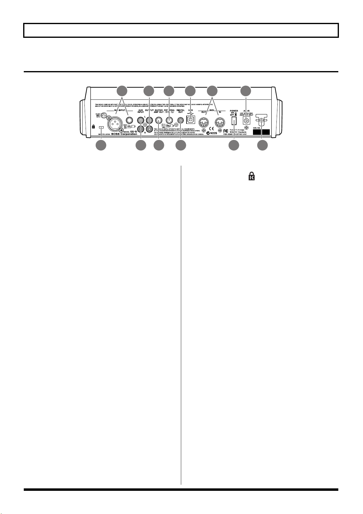
Panel Descriptions
Rear Panel
fig.00-042
2 4 6
1. MIC INPUT Jack/Connector
Input jack/connector for use with mics. Both standard
TRS type and XLR type are provided.
* Use only one of these jacks at a time.
* Not compatible with phantom power.
2. AUX INPUT Jacks L/R
Used for connecting a CD player or similar audio
device, rhythm machine, sound module, or similar
devices.
3. OUTPUT Jacks L/R
Used for connecting to an audio set, recorder, mixer, or
similar equipment.
31 5 7
8
10
9
12.
Security Slot ( )
http://www.kensington.com/
1112
4. GUITAR AMP OUT Jack
Connect your guitar amp here.
5. EXP PEDAL/CTL 1,2
(Expression Pedal/Control Pedal 1,2) Jack
Connect an optional expression pedal (such as the EV-
5) or foot switch (such as the FS-5U) here.
6. DIGITAL OUT Connector
Outputs digital audio signals.
7. USB Connector
Use a USB cable to connect this connector to your
computer to exchange data between the GS-10 and the
computer.
8. MIDI IN/OUT Connector
Connect an external MIDI device to these connectors to
transmit and receive MIDI messages
9. POWER switch
Turns the power on and off.
10.
AC Adaptor Jack
Connect the included AC adaptor (BRC series) here.
11.
Cord Hook
Hook the AC adaptor cord here to prevent the adaptor
plug from being disconnected.
12

Signal Flow
fig.00-043
Panel Descriptions
Computer
Expression Pedal
Foot Switch
Guitar/Bass
Mic
CD/MD
EXP/CTL 1, 2
GUITAR/
BASS
MIC
INPUT
AUX
INPUT
INPUT
SELECT
Recorder
etc.
DIGITAL
GS-10 IN
OUT
CONTROL IN
GS-10 OUT
MIDI
SELECT
CONTROL
A/D D/A
MULTI EFFECTS
CONTROL OUT
MIDI IN
MIDI OUT
USB
MIDI OUT
MIDI IN
PHONES
AMP OUT
OUTPUT
GUITAR
Speaker
Headphones
Sound
Module
Sequencer
Guitar Amp
Mixer etc.
Audio signal
Control or MIDI signal
13
Chapter 1 Playing Sounds
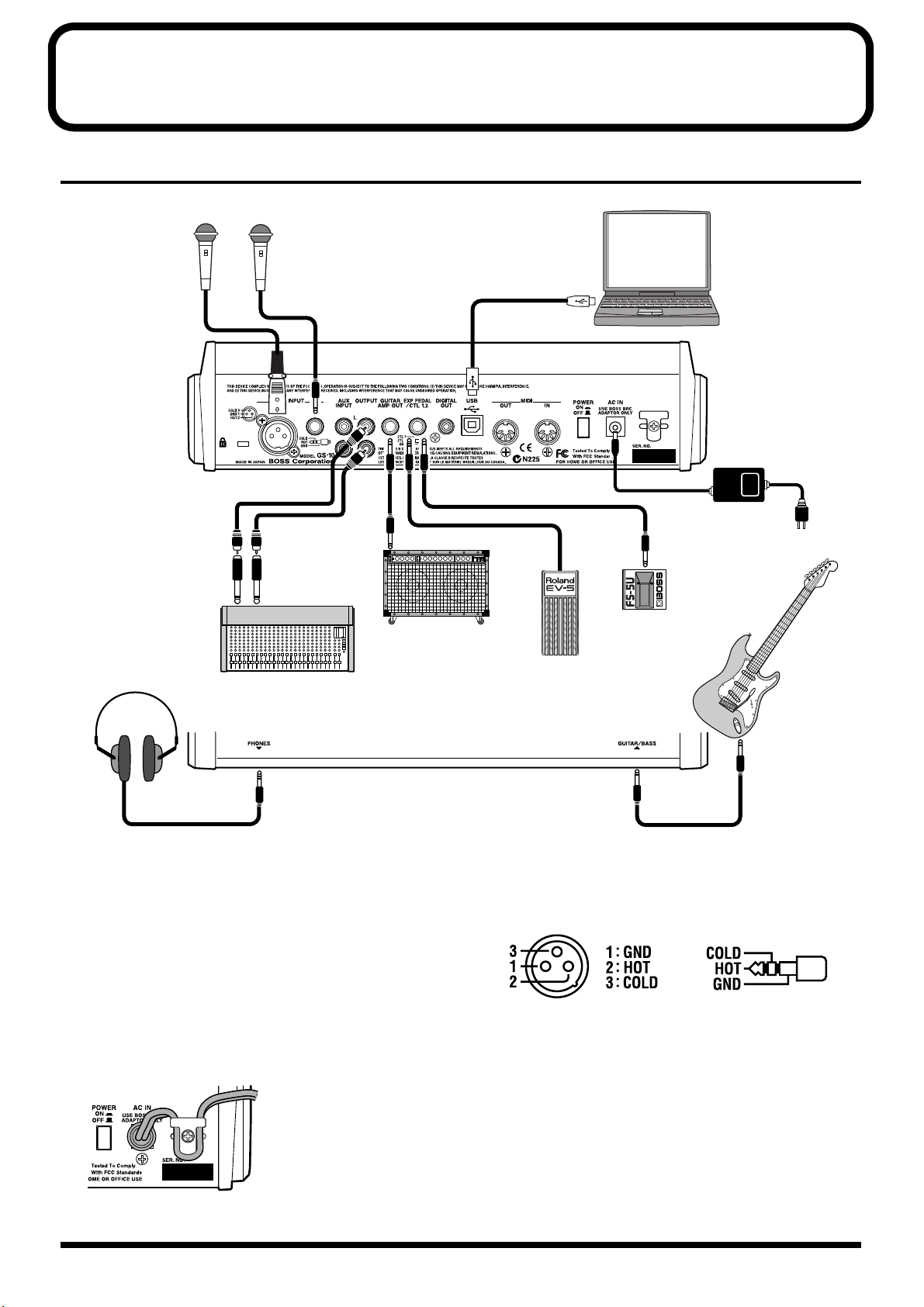
Making the Connections
fig.01-010
Mic
or
Computer
AC Adaptor
(BRC series)
Guitar Amp
Stereo Headphones
Mixer
* To prevent malfunction and/or damage to speakers or other
devices, always turn down the volume, and turn off the power
on all devices before making any connections.
* Turn up guitar amp and audio amp volume levels and the GS-
10’s OUTPUT LEVEL only after turning on the power to all
connected devices.
● To prevent the inadvertent disruption of power to your
unit (should the plug be pulled out accidentally), and to
avoid applying undue stress to the AC adaptor jack,
anchor the power cord using the cord hook, as shown in
the illustration.
fig.01-020
Guitar
or
Bass
Foot Switch
(FS-5U, etc.)
Expression Pedal
(Roland EV-5, etc.)
● This instrument is equipped with balanced (XLR/TRS)
type MIC INPUT jacks. Wiring diagrams for these jacks
are shown below. Make connections after first checking
the wiring diagrams of other mic you intend to connect.
fig.01-021
* Not compatible with phantom power.
● Howling could be produced depending on the location
of mics relative to speakers. This can be remedied by:
1. Changing the orientation of the mic(s).
2. Relocating mic(s) at a greater distance from
speakers.
3. Lowering volume levels.
14
Chapter 1 Playing Sounds
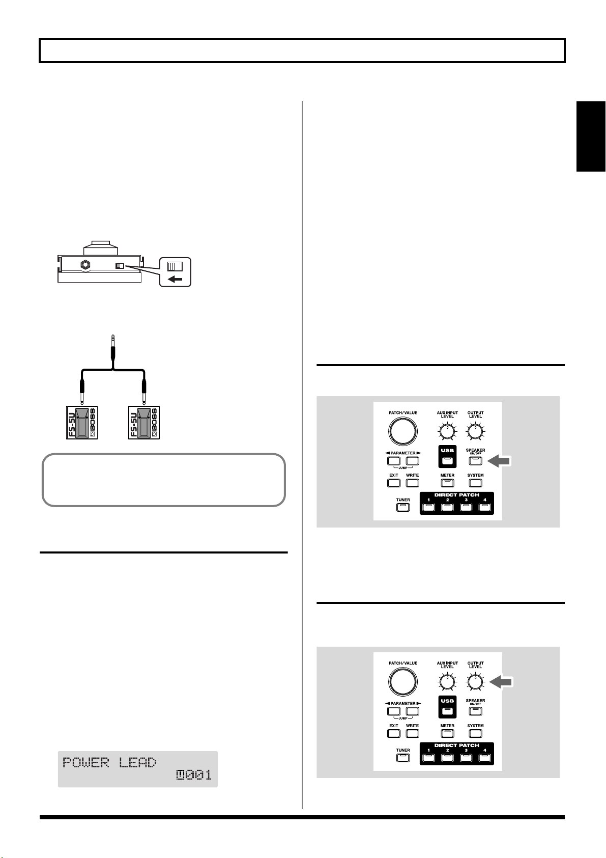
● When using the unit with an expression pedal connected
to the EXP PEDAL/CTL 1,2 jack, set Minimum Volume
to the “MIN” position.
● Use only the specified expression pedal (Roland EV-5;
optional). By connecting any other expression pedals,
you risk causing malfunction and/or damage to the unit.
● When using the unit with a foot switch (FS-5U; optional)
connected to the EXP PEDAL/CTL 1,2 jack, set the
polarity switch as shown below.
fig.01-030
Polarity
Switch
* You can use the special (optional Roland) PCS-31 connector
cord to connect two foot switches.
fig.01-040
PCS-31
White Red
* Upon power-up, the patch most recently selected when the
power was last turned off is selected.
* This unit is equipped with a protection circuit. A brief interval
(a few seconds) after power up is required before the unit will
operate normally.
3. Next, turn on the power to guitar amp and audio
devices.
Turning Off the Power
1. Before turning off the power, confirm the following.
• Is the volume on the GS-10, your amp, and all other
connected devices turned down to the minimum level?
2. Turn off the power to guitar amp and audio devices.
3. Turn the GS-10’s power off.
Using the GS-10’s Speakers
Press [SPEAKER ON/OFF], causing the indicator to light.
fig.01-050
Section 1
When using the unit with a foot switch (the optional FS5U) connected to the EXP PEDAL/CTL 1,2 jack, make
the settings given on p. 59.
Turning On the Power
Once the connections have been completed, turn on power to
your various devices in the order specified. By turning on
devices in the wrong order, you risk causing malfunction
and/or damage to speakers and other devices.
1. Before turning on the power, confirm the following.
• Are all external devices properly connected?
• Is the volume on the GS-10, your amp, and all other
connected devices turned down to the minimum level?
2. Switch ON the POWER switch on the GS-10’s rear panel.
A few seconds later, the unit enters the ordinary
performance mode. The screen that appears at this point
is called the “Play screen.”
fig.01-050d
* When not using the GS-10’s speakers, press [SPEAKER ON/
OFF], so the indicator is off.
Adjusting the Output Level
Adjust the GS-10’s output level and speaker volume with the
OUTPUT LEVEL knob.
fig.01-060
15

Chapter 1 Playing Sounds
Setting Output Device (Amps) (OUTPUT SELECT)
Select the type of output device connected to the OUTPUT
jack or GUITAR AMP OUT jack.
To derive the maximum performance from the GS-10, be
sure to make the correct setting for OUTPUT SELECT,
the one that’s most suitable for your setup.
fig.01-061
2
13
1. Press [SYSTEM], causing the indicator to light.
The Output Select settings screen appears.
fig.01-070d
Combo Return
Use this setting when connecting to RETURN with a
combo amp.
Stack Return
Use this setting when connecting to RETURN of a stack
amp or rack mounted power amp.
3. Press [EXIT] to return to the Play screen.
* Set OUTPUT SELECT as shown below, when the PREAMP/
SPEAKER type (p. 29) is set to CONCERT 810, SESSION,
BASS 360, T.E., B-MAN, FLIP TOP, Bass Clean, Bass
Crunch, Bass HiGain, or Mic Preamp.
When connecting to an audio amp or similar equipment:
Line/Phones
When connecting to a guitar amp:
Combo Amp or Combo Return
When connecting to a bass amp:
Stack Amp or Stack Return
Guitar Tuning
You can use the GS-10’s built-in “tuner function” to tune
your guitar.
For instructions on using this function, refer to “Tuning
the Guitar” (p. 64).
2. Turn the PATCH/VALUE dial to select the type of
device connected to the OUTPUT jack or GUITAR
AMP OUT jack.
Line/Phones
Set this when connecting the OUTPUT jack to an audio
set or when connecting a recorder for recording.
Use this setting also when using the GS-10’s speakers or
headphones.
Combo AMP
Use this setting when connecting to the guitar input of a
combo amp (where the amp and speaker or speakers are
combined in a single unit).
Stack AMP
Use this setting when connecting to the guitar input of a
stack-type guitar amp (where the amp and speaker or
speakers are separated).
16

Chapter 1 Playing Sounds
Connecting Audio Devices to the AUX INPUT Jack
When using a CD or MD player, rhythm machine, or similar
device for practice, connect these device to the AUX INPUT
jack on the rear panel.
fig.01-080
CD/MD Player
Rhythm Machine
Use the AUX INPUT knob on the front panel to adjust the
input volume level for AUX INPUT.
* Setting the input level too high may result in oscillation.
fig.01-090
Using the Digital Output
Digital signals are output from the DIGITAL OUT connector
on the rear panel. You can connect this directly to the digital
in connector of a digital recorder or other device and record
with no degradation in sound quality.
fig.01-100
DIGITAL IN
Digital Recorder
Section 1
The input sounds from the AUX INPUT jack are mixed with
the guitar sounds within the GS-10, making this a convenient
feature when using the GS-10’s speakers or headphones.
* The mixed sound is not output from DIGITAL OUT.
AUX INPUT
You can set INPUT SELECT and use USB to record the
input sounds from the AUX INPUT jack to your
computer, and record to a recorder using DIGITAL OUT.
You can also add effects to the sounds input from the
AUX INPUT jack.
For instructions on setting INPUT SELECT, refer to
“Selecting the Input (INPUT SELECT)” (p. 19).
17

Chapter 2 Creating Your Own Favorite Tones (Patches)
What is a Patch?
The GS-10 can store 200 combinations (or “sets”) of effects
and parameter settings. Each of these sets is called a “patch.”
Patches include both User patches and Preset patches.
fig.02-010
U100
● Patch Name
● Input Select
U003
● Effects
U002
● Assign 1–8
● Master
U001
● Noise Suppressor
● Patch Name
● Effect Chain
● Input Select
● Effects
● Assign 1–8
● Master
● Noise Suppressor
● Effect Chain
User Patches
User Patches (U001–U100)
Newly created effects settings are saved in the User patches.
*A “U” appears in the display when a User patch is being used.
fig.02-020d
P200
● Patch Name
● Input Select
P103
● Effects
P102
● Assign 1–8
● Master
P101
● Noise Suppressor
● Patch Name
● Effect Chain
● Input Select
● Effects
● Assign 1–8
● Master
● Noise Suppressor
● Effect Chain
Preset Patches
How to Select Patches (Patch Change)
When the Play screen is showing in the display, you can
switch patches using the PATCH/VALUE dial or DIRECT
PATCH [1]–[4] (p. 27).
fig.02-040
* If you want to set a limit to the number of patches that can be
selected with the PATCH/VALUE dial, change the system
function settings (p. 65).
* Settings currently being edited are cleared when you switch
patches. If you want to save the setting changes you’ve made,
use the Write procedure (p. 25).
About the Display Indication
Preset Patches (P101–P200)
The Preset patches contain effect settings that really help
bring out the special characteristics of the GS-10.
Although you cannot overwrite the Preset patches with your
own settings, you can change (edit) a Preset patch’s settings,
then save the result as a User patch. (p. 25)
*A “p” appears in the display when a Preset patch is being
used.
fig.02-030d
The following information appears in the Play screen.
fig.02-050d
Patch Name
User/Preset Number
If the Patch Does Not Switch
On the GS-10, you cannot switch patches in any screen other
than the Play screen. Press [EXIT] to return to the Play screen
(p. 15).
18

Chapter 2 Creating Your Own Favorite Tones (Patches)
Selecting the Input (INPUT SELECT)
This selects the input signal to which the effects are added.
This is also used for setting the type of device connected to
the input connector.
To derive the maximum performance from the GS-10, be
sure to make the correct setting for INPUT SELECT, the
one that’s most suitable for your setup.
You may not be able to achieve the expected effect if this
is not set correctly.
fig.02-051
2
1
1. Press [INPUT SELECT].
The Input Select settings screen appears.
fig.02-060d
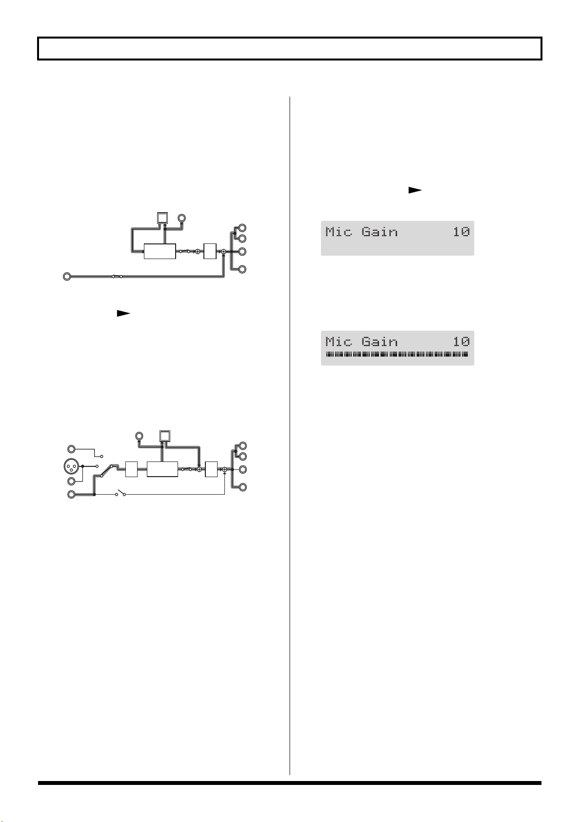
2. Turn the PATCH/VALUE dial to change the settings.
Guitar:
You can add effects to the signals input from the
GUITAR/BASS INPUT connector (when a guitar is
connected). Signals from MIC INPUT are disregarded,
and the signals input to the GS-10 from the USB or AUX
INPUT connectors are mixed with the effect output.
fig.02-070
DIGITAL
USB
OUT
D/A
L
R
OUTPUT
GUITAR
AMP OUT
PHONES
GUITAR/
BASS
MIC
INPUT
AUX
INPUT
A/D
MULTI
EFFECTS
Bass:
You can add effects to the signals input from the
GUITAR/BASS jack (when a bass is connected). Signals
from MIC INPUT are disregarded, and the signals input
to the GS-10 from the USB or AUX INPUT connectors are
mixed with the effect output.
fig.02-080
GUITAR/
BASS
MIC
INPUT
AUX
INPUT
DIGITAL
A/D
OUT
USB
MULTI
EFFECTS
D/A
L
R
OUTPUT
GUITAR
AMP OUT
PHONES
* Depending on the type of bass guitar you are using, you may
not be able to achieve the intended effect if the input level to the
GS-10 is excessively high.
In such cases, lower the volume or tone of your bass guitar.
Microphone:
You can add effects to the signals input from the MIC
INPUT connector. Signals from GUITAR/BASS jack are
disregarded, and the signals input to the GS-10 from the
USB or AUX INPUT connectors are mixed with the effect
output.
fig.02-090
GUITAR/
BASS
MIC
INPUT
AUX
INPUT
DIGITAL
A/D
OUT
USB
MULTI
EFFECTS
D/A
L
R
OUTPUT
GUITAR
AMP OUT
PHONES
* After setting INPUT SELECT to Microphone, you can press
PARAMETER [ ] to set the mic gain (p. 20).
USB (Gtr/Mic):
You can add effects to the signals input from the USB
connector (for sounds in the guitar and vocal registers).
Signals from GUITAR/BASS and MIC INPUT are
disregarded, and the signals input to the GS-10 from the
AUX INPUT connector are mixed with the effect output.
fig.02-100
DIGITAL
USB
OUT
L
OUTPUT
MULTI
EFFECTS
AUX
INPUT
* After setting INPUT SELECT to USB (Gtr/Mic), you can
press PARAMETER [ ] to set the USB input level (p. 78).
D/A
R
GUITAR
AMP OUT
PHONES
Section 2
19
Chapter 2 Creating Your Own Favorite Tones (Patches)
USB (Bass):
You can add effects to the signals input from the USB
connector (for sounds in the bass and similar registers).
Signals from GUITAR/BASS INPUT and MIC INPUT
are disregarded, and the signals input to the GS-10 from
the AUX INPUT connector are mixed with the effect
output.
fig.02-110
DIGITAL
USB
OUT
L
OUTPUT
R
GUITAR
AMP OUT
PHONES
AUX
INPUT
MULTI
EFFECTS
D/A
* After setting INPUT SELECT to USB (Bass), you can press
PARAMETER [ ] to set the USB input level (p. 78).
AUX:
This setting is used when selecting the input signal from
the AUX INPUT connector. Signals input from the
GUITAR/BASS INPUT and MIC INPUT are
disregarded, and the signals input to the GS-10 via USB
are mixed with the effect output.
fig.02-120
DIGITAL
USB
OUT
D/A
L
R
OUTPUT
GUITAR
AMP OUT
PHONES
GUITAR/
BASS
MIC
INPUT
AUX
INPUT
A/D
MULTI
EFFECTS
Setting the Mic Input Level (MIC GAIN)
This sets the mic input level when INPUT SELECT is set to
Microphone.
* The mic gain setting is a global setting used by all patches.
1. Press PARAMETER [ ].
The MIC GAIN settings screen appears in the display.
fig.02-130d
2. Adjust the gain by turning the PATCH/VALUE dial
while picking up sounds with the mic.
Adjust the level so that the level meter does not fluctuate
beyond the maximum allowable level.
fig.02-140d
* Set the volume for the sound being miked (acoustic guitar,
vocals, etc.) to the level to be used in performance.
* Setting the mic gain too high may result in oscillation.
3. Press [EXIT] to return to the Play screen.
20

Chapter 2 Creating Your Own Favorite Tones (Patches)
Adjusting the Tones with the Knobs
The GS-10 panel features 13 knobs for adjusting effect tones.
You can use these knobs to make slight adjustments to tones
in the selected patch quickly and easily.
fig.02-150
PREAMP GAIN:
Adjusts the degree of preamp distortion. The distortion gets
stronger as the knob is turned to the right.
OD/DS (Overdrive/Distortion) DRIVE
Adjusts the degree of overdrive or distortion. The distortion
appears stronger as the knob is turned to the right.
OD/DS (Overdrive/Distortion) LEVEL:
Adjusts the overdrive/distortion volume level. The volume
increases as the knob is turned to the right.
DELAY FEEDBACK:
Adjusts the number of times the delay is repeated. The
number of repeats increases as the knob is turned to the
right.
DELAY LEVEL:
Adjusts the volume level of the delay sound. The delay
sound increases as the knob is turned to the right.
CHORUS LEVEL:
Adjusts the volume level of the chorus sound. The chorus
sound increases as the knob is turned to the right.
REVERB LEVEL:
Adjusts the volume level of the reverb sound. The reverb
sound increases as the knob is turned to the right.
Section 2
PREAMP BASS:
Adjusts the sound quality of the preamp’s low-frequency
range. The low frequencies are boosted as the knob is turned
to the right.
PREAMP MIDDLE:
Adjusts the sound quality of the preamp’s midrange. The
midrange frequencies are boosted as the knob is turned to
the right.
PREAMP TREBLE:
Adjusts the sound quality of the preamp’s high-frequency
range. The high frequencies are boosted as the knob is turned
to the right.
PREAMP PRESENCE:
Adjusts the sound quality in the preamp’s ultra-highfrequency range. The ultra-high frequencies are boosted as
the knob is turned to the right.
PREAMP LEVEL:
Adjusts the preamp volume level. The volume increases as
the knob is turned to the right.
COMP (Compressor) SUSTAIN:
Adjusts the compressor’s sustain effect (an effect that keeps
the sound playing). The effect is strengthened as the knob is
turned to the right.
21
Chapter 2 Creating Your Own Favorite Tones (Patches)
2 51
3
Turning the Effect On and Off
The GS-10’s internal effects are switched on and off with
button controls. The indicator for an effect’s ON/OFF button
lights up when the effect is enabled.
fig.02-160
1,2,3 4
1. Press the ON/OFF button for the effect you want to be
able to switch on and off.
The settings for the selected effect appear in the display.
* With FX-1 and FX-2, the settings for the currently selected
effect are shown.
fig.02-170d
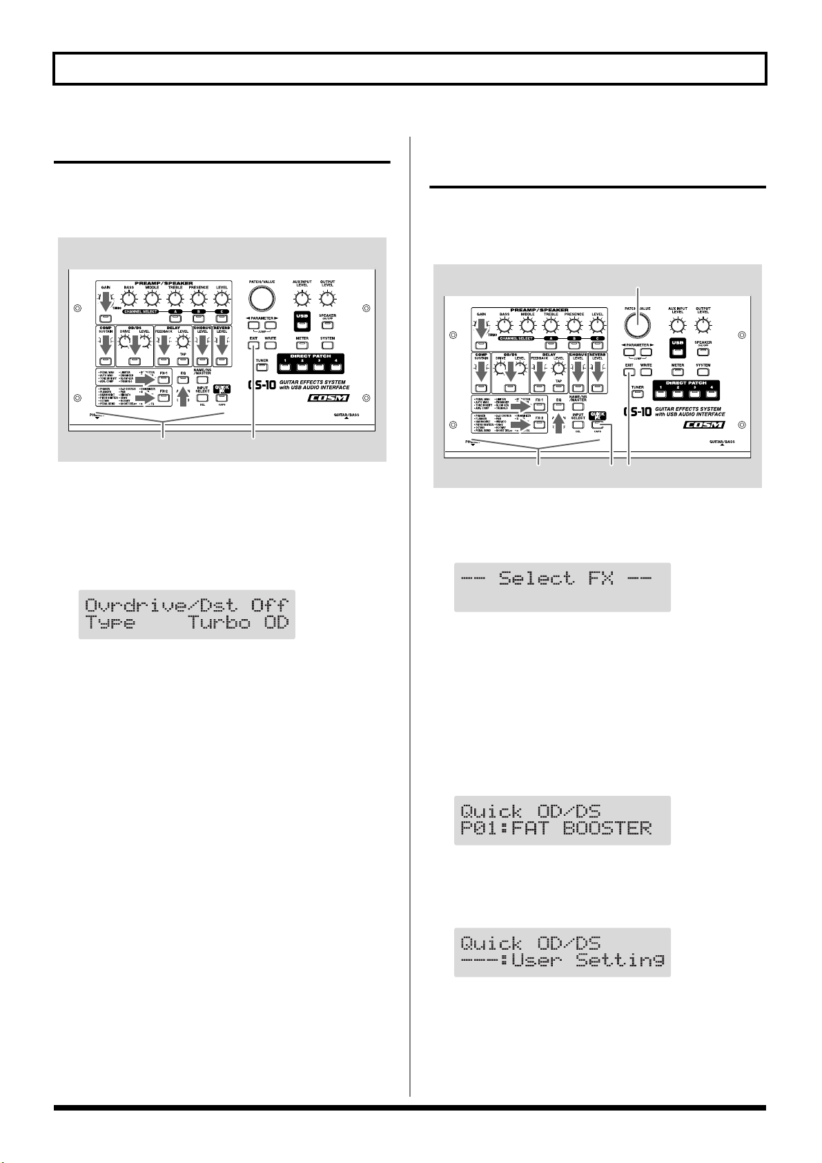
Setting the Effects Simply (QUICK FX)
Each effect includes prepared sample settings called “Quick
Settings.” You can easily create new effect sounds just by
selecting and combining these Quick Settings.
fig.02-171
1. Press [QUICK FX].
The effects selection screen appears in the display.
fig.02-180d
2. Press the ON/OFF button again to switch the effect on
or off.
* The effect name flashes in the display when that effect is
disabled.
3. To select another effect to be switched on and off,
repeat Steps 1 and 2.
4. Press [EXIT] to return to the Play screen.
* If you want to save a tone with the settings you’ve made, use
the Write procedure (p. 25) to save the tone to a User patch.
* Performing Step 1 while editing an effect takes you to the
status following Step 2.
2. Press the ON/OFF button for the effect you want to
select for Quick Settings.
The name of the effect being set with Quick Settings
appears in the upper row of the display, and the “Quick
Settings Name” currently selected for that effect appears
in the lower row of the display.
fig.02-190d
* The following appears in the display immediately after patches
are changed or when the settings in Quick settings are
changed by editing the parameters.
fig.02-200d
* The upper row of the display flashes when the selected effect is
switched off. Even when using the Quick Settings, you can
switch effects on and off with the effect ON/OFF buttons.
22

Chapter 2 Creating Your Own Favorite Tones (Patches)
1 61
23
3. Rotate the VALUE dial to select the Quick Setting you
want.
The tone switches to that of the selected sample settings.
* You can select “—: User Setting” to return the settings to
their condition prior to selecting the Quick Settings.
4. To select Quick Settings for another effect, repeat Steps
2 and 3.
* Even after performing this procedure, the settings selected in
Step 3 are maintained as is and carried over to the Quick
Settings for the next effect.
5. Press [EXIT] to return to the Play screen.
* If you want to save a tone with the settings you’ve made, use
the Write procedure (p. 25) to save the tone to a User patch.
Making More Precise Effect Settings
Each effect comprises several different kinds of parameters.
You can more precisely create the sounds you want by
editing each of these parameters individually.
fig.02-210
1. Press the on/off button for the effect with the settings
you want to change.
The parameters for the selected effect appear in the
display.
Section 2
2. Press PARAMETER [ ] [ ] to select the
parameter whose settings are to be changed.
When more than one parameter is shown in the display,
press PARAMETER [ ] [ ] to move the cursor to
the parameter to be set.
You can jump to the core parameters by pressing
PARAMETER [ ] (or [ ]) while holding down
PARAMETER [ ] (or [ ]). With items for which
there aren’t that many parameters, the GS-10 jumps to
the last (or first) parameter.
3. Rotate the VALUE dial to change the value of a setting.
4. Repeat Steps 2 and 3 for any other parameter settings
you want to change.
5. If you further want to change parameter settings in any
other effects, repeat Steps 1 through 4.
6. Press [EXIT] to return to the Play screen.
* If you want to save a tone with the settings you’ve made, use
the Write procedure (p. 25) to save the tone to a User patch.
23

Chapter 2 Creating Your Own Favorite Tones (Patches)
3 1
22
Naming Patches
Each patch can be given a name (Patch Name) consisting of
up to sixteen characters. You’ll probably want to take
advantage of this feature by assigning names that suggest the
sound you’ll obtain, or the song in which it’ll be used.
fig.02-220
23
13
1. Press [NAME/NS/MASTER] so that the Name edit
screen appears in the display.
* With each press of [NAME/NS/MASTER], you move to the
next item that can be set, in this order:
Name → Noise Suppressor → Master → Foot Volume →
Effect Chain.
fig.02-230d
Changing the Connection Order of Effects (Effect Chain)
Here’s how you can change the order in which the effects are
connected.
fig.02-240
1. Press [NAME/NS/MASTER] until “Effect Chain”
appears in the display.
* With each press of [NAME/NS/MASTER], you move to the
next item that can be set, in this order:
Name → Noise Suppressor → Master → Foot Volume →
Effect Chain.
fig.02-250d
2. Press PARAMETER [ ] [ ] to move the cursor to
the text area you want to edit.
3. Rotate the PATCH/VALUE dial to change the
characters.
* You can use the following functions when changing text
characters.
CAPS: Switches the character at the cursor position
between upper and lower case.
INS: Inserts a blank space at the cursor position.
DEL: Deletes the character at the cursor position and
shifts the characters following it to the left.
4. If you want to edit names further, repeat Steps 2 and 3.
5. If you want to save the sequence you’ve set up, use the
Write procedure (p. 25) to save it to a User patch.
Press [EXIT] to return to the Play screen.
* Effects are shown in lowercase letters when turned off.
2. Use the PATCH/VALUE dial or PARAMETER [ ]
[] to move the cursor to the point where you want
to have an effect inserted.
3. Press the On/Off button for the effect you want to
insert.
The selected effect is inserted at the cursor position.
* Use [ASSIGN] to assign Foot Volume.
4. If you want to change the sequence further, repeat
Steps 2 and 3.
5. If you want to save the sequence you’ve set up, use the
Write procedure (p. 25) to save it to a User patch.
Press [EXIT] to return to the Play screen.
Effects can be switched on and off even while making
the settings for the connection order (excluding FV, NS,
and USB).
With effects appearing to the left and right of the cursor,
the ON/OFF button corresponding to the effect can be
pressed to turn them on/off.
24

Chapter 3 Saving the Tones You Have Created
2,4
3
Storing Patches (PATCH WRITE)
When you want to keep a tone created with the Quick
Settings or a tone with altered parameter values, use the
“Write procedure” to save it to a User patch.
* If the power is turned off, or if the tone is switched (Patch
Change; p. 18) before you’ve carried out the Write procedure,
the newly created tone will be discarded.
fig.03-010
2
1,3
1. Press [WRITE].
The screen for specifying the save-destination User patch
appears in the display.
fig.03-020d
Save-destination patch
Copying Patches
You can copy a Preset or User patch to another User patch.
fig.03-030
Section 3
1. Select the copy-source patch (refer to “How to Switch
Patches”; p. 18).
2. Press [WRITE].
The screen for specifying the copy-destination patch
number appears in the display.
fig.03-040d
Copy-destination patch
2. Rotate the VALUE dial to select the save-destination
User patch.
* This step is unnecessary if the current User patch is
acceptable.
* To cancel the Write procedure, press [EXIT]. The Play screen
returns to the display.
3. Press [WRITE].
The GS-10 switches to the write-destination patch, and
you’re returned to the Play screen.
* The sound of the patch previously stored at the write
destination will be lost once the write is executed.
3. Rotate the PATCH/VALUE dial to select the copy-
destination User patch.
* To cancel the copy, press [EXIT]. The Play screen returns to
the display.
4. Press [WRITE].
The GS-10 switches to the copy-destination patch, and
you’re returned to the Play screen.
* The sound of the patch previously stored at the copy
destination will be lost once the copy is executed.
25
Chapter 3 Saving the Tones You Have Created
2,4
3
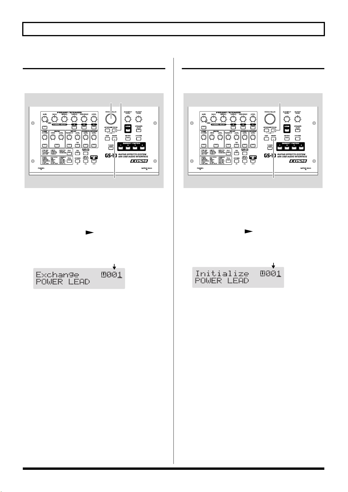
Exchanging Patches
On the GS-10, you can “swap” or exchange the positions of
two User patches. The following explains how this is done.
fig.03-050
4 3
2,5
1. Select the exchange source patch.
* Refer to “Patch Change” (p. 18).
2. Press [WRITE].
3. Press PARAMETER [ ].
The screen for specifying the exchange-destination patch
number appears in the display.
fig.03-060d
Exchange-destination patch
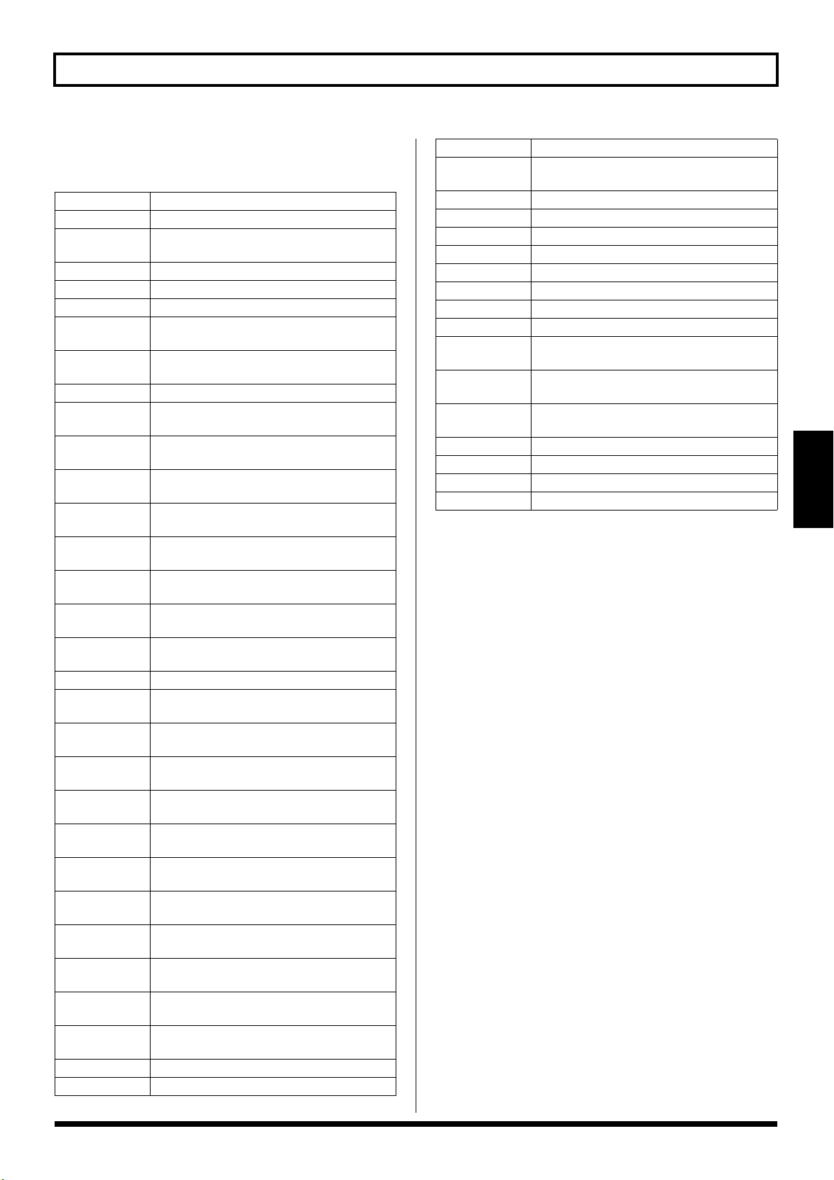
Initializing Patches
You can return (initialize) the User patches to their original
standard settings.
fig.03-061
1. Select the User patch you want to initialize.
* Refer to “Patch Change” (p. 18).
2. Press [WRITE].
3. Press PARAMETER [ ] twice.
The screen for specifying the initialize-destination patch
number appears in the display.
fig.03-062d
User patch to be initialized
4. Rotate the PATCH/VALUE dial to select the exchange
destination User patch.
* To cancel the exchange, press [EXIT]. The Play screen returns
to the display.
5. Press [WRITE].
The patch stored in the exchange source memory
location and the patch stored in the exchange destination
memory location are exchanged, and you’re returned to
the Play screen.
* You can use the PATCH/VALUE dial to change the selection
of the User patch to be initialized.
* To cancel the initialization, press [EXIT]. The Play screen
returns to the display.
4. Press [WRITE].
The GS-10 switches to the initialized patch, and the Play
screen returns to the display.
* The tones stored in patches are lost once the initialization is
executed.
26

Chapter 3 Saving the Tones You Have Created
2,4
1,3
Copy-destination channel
Copy-source channel
Registering Your Favorite Patches (DIRECT PATCH)
You can register preferred patches to DIRECT PATCH [1]–[4]
and then press these buttons to call up the corresponding
patches directly.
fig.03-070
32
4 1
1. Press [SYSTEM] a number of times until “DIRECT
PATCH” is displayed.
fig.03-080d
Copying the PREAMP/SPEAKER Settings to Another Channel
You can take the PREAMP/SPEAKER settings for one
channel and copy them to another channel.
fig.03-090
Section 3
1. Select the copy-source channel.
2. Press [WRITE].
3. Press CHANNEL SELECT [A]–[C] to select the copy-
destination channel.
The channel copy screen appears in the display.
2. Press PARAMETER [ ] [ ] to select the number
of the DIRECT PATCH button to which you want to
register the patch.
3. Use the PATCH/VALUE dial to select the patch you
want to register.
4. Press [EXIT] to return to the Play screen.
You can also register patches by selecting the patch in
the Play screen, then pressing one of the
[1]–[4] buttons after pressing the [WRITE] button. In this
case, the patch appearing in the display is registered.
* When a patch is registered using this method, the current
settings are also saved along with the patch when it’s
registered. If you want to register only the patch, use the
regular registration method.
DIRECT PATCH
* If you press the button for the same channel as the copy source,
a channel other than the copy-source channel is selected for the
copy destination.
fig.03-100d
* To change the copy-source or copy-destination channel, press
PARAMETER [ ] [ ] to move the cursor to the copysource or copy-destination channel, then press CHANNEL
SELECT [A]–[C].
You can alternatively rotate the PATCH/VALUE dial to
change the channel at the cursor position.
* When the copy-source channel is changed, the tone is changed
as well.
* To cancel the copy, press [EXIT]. The Play screen returns to
the display.
4. Press [WRITE].
The settings are copied.
* If you want to keep a tone for which you have made settings,
use the “Write procedure” (p. 25) to save it to a User patch.
27

Chapter 4 Introduction to Effects and Parameters
In this chapter you will find detailed descriptions for each of
the GS-10’s onboard effects, and the parameters used to
control them.
The sound being input to each effect is called the “direct
sound,” and the sound modified by the effect is called the
“effect sound.”
* Setting values for gain– and volume–related parameters in the
effects too high may result in oscillation.
To derive the maximum performance from the GS-10,
be sure to make the correct setting for INPUT SELECT
(p. 19), the one that’s most suitable for your setup.
You may not be able to achieve the expected effect if
this is not set correctly.
* Depending on the type of bass guitar you are using, you
may not be able to achieve the intended effect if the input
level to the GS-10 is excessively high. In such cases, lower
the volume or tone of your bass guitar.
The trademarks listed in this document are trademarks
of their respective owners, which are separate companies
from BOSS. Those companies are not affiliated with
BOSS and have not licensed or authorized BOSS’s GS-10.
Their marks are used solely to identify the equipment
whose sound is simulated by BOSS’s GS-10.
PREAMP/SPEAKER (Preamp/ Speaker Simulator)
COSM technology plays an indispensable role in simulating
the distinguishing characteristics of various guitar amps in
the “Preamp” section, and is also used to simulate various
speaker sizes and cabinet constructions in the “Speaker
Simulator.”
Parameter Value
On/Off Off, On
CH Select A, B, C
Type refer to p. 29
Gain 0–120
Bass 0–100
Middle 0–100
Treble 0–100
Presence 0–100
Level 0–100
Bright Off, On
Gain SW Low, Middle, High
SP Type (*) Off, Original, 1x8”, 1x10”, 1X12”,
1X15”, 1X18”, 2X12”, 2X15”,
4X10”, 4X12”, 8X10”, 8X12”,
Custom 1, Custom 2
Mic Type (*) DYN57, DYN421, CND451,
CND87, FLAT
Mic Dis. (*) Off Mic, On Mic
Mic Pos. (*) Center, 1–10
Mic Level (*) 0–100
Direct Level (*) 0–100
(*) No effect when OUTPUT Select is set to “Line/Phones.”
On/Off (Effect On/Off)
Turns the PREAMP/SPEAKER effect on/off.
CH Select (Channel Select)
Selects the preamp channel whose settings are to be changed.
28
Chapter 4 Introduction to Effects and Parameters
Type
This sets the type of the guitar preamp.
JC-120 This is the sound of the Roland JC-120.
Jazz Combo This is a sound suited to jazz.
Full Range
Warm Clean This gives a mellow, clean sound.
Clean TWIN This models a Fender Twin Reverb.
Pro Crunch This models a Fender Pro Reverb.
Tweed
Crunch
Blues This is a sound suited to blues.
Wild Crunch
VO Drive
VO Lead
MATCH Drive
Fat MATCH
BG Lead
BG Drive
BG Rhythm
Smooth Drive This is a smooth drive sound.
MS1959 (I)
MS1959 (II)
MS1959 (I+II)
MS HiGain
Power Stack
R-FIER Red
R-FIER Orng
R-FIER Vint
T-AMP Clean
T-AMP Crunch
T-AMP Lead
SLDN This models a Soldano SLO-100.
Drive Stack This is a drive sound with high gain.
This is a sound with flat response. Good for
acoustic guitar
This models a Fender Bassman 4 x 10”
Combo.
This is a crunch sound that can produce
natural distortion.
This is a crunch sound with wild distortion.
This models the drive sound of a VOX AC30TB.
This models the lead sound of the VOX
AC-30TB.
This models the sound input to left input
on a Matchless D/C-30.
This models the sound of a MATCHLESS
with a modified high gain.
This models the lead sound of the MESA/
Boogie combo amp.
This models a MESA/Boogie with TREBLE
SHIFT SW on.
This models the rhythm channel of a
MESA/Boogie.
This models the sound input to Input I on a
Marshall 1959.
This models the sound input to Input II on
a Marshall 1959.
This models the sound of a Marshall 1959
with Inputs I and II connected in parallel.
This models the sound of a Marshall with a
modified midrange boost.
This provides the sound of a stack amp
with active type tone circuitry.
This models the lead channel of a MESA/
Boogie Dual Rectifier.
This models the rhythm channel of a
MESA/Boogie Dual Rectifier.
This models a MESA/Boogie Rectifier with
VINTAGE SW on.
This models a Hughes & Kettner Triamp
AMP1.
This models a Hughes & Kettner Triamp
AMP2.
This models a Hughes & Kettner Triamp
AMP3.
Lead Stack This is a lead sound with high gain.
5150 Drive
Metal Stack This is a drive sound suited to metal.
Metal Lead This is a lead sound suited to metal.
CONCERT 810 This models a Ampeg SVT.
SESSION This models a SWR SM-400.
BASS 360 This models a acoustic 360.
T.E. This models a Trace Elliot AH600SMX.
B-MAN This models a Fender Bassman100.
FLIP TOP This models a Ampeg B-15.
Bass Clean
Bass Crunch
Bass HiGain
Mic Preamp Preamp suitable for vocals.
Custom 1 Custom amp 1
Custom 2 Custom amp 2
Custom 3 Custom amp 3
* When the type is set to CONCERT 810, SESSION, BASS
360, T.E., B-MAN, FLIP TOP, Bass Clean, Bass Crunch,
Bass HiGain, or Mic Preamp set OUTPUT SELECT (p. 16)
as shown below to match the GS-10 to the type of amp to be
connected.
When connecting to an audio amp or similar equipment:
Line/Phones
When connecting to a guitar amp:
Combo Amp or Combo Return
When connecting to a bass amp:
Stack Amp or Stack Return
This models the lead channel of a Peavey
EVH 5150.
This clean sound is great for use with bass
guitars.
This is a crunch sound with natural distortion that sounds great with bass guitars.
This is a high-gain sound suitable for use
with bass guitars.
Section 4
29

Chapter 4 Introduction to Effects and Parameters
When CUSTOM 1–3 is selected for Type
You can set the following parameters when Type is set to
CUSTOM.
“Customizing the COSM Amps” (p. 55)
EDIT CUSTOM PRE 1–3
Parameter Value
Type JC Clean, TW Clean, Crunch,
VO Lead, BG Lead,
MS1959 Stk, Modern Stk
Bottom -50–+50
Edge -50–+50
Bass Freq -50–+50
Treble Freq -50–+50
Preamp Low -50–+50
Preamp High -50–+50
Gain
Adjusts the distortion of the amp.
Bass
Adjusts the tone for the low frequency range.
Middle
Adjusts the tone for the middle frequency range.
Treble
Adjusts the tone for the high frequency range.
Presence
Adjusts the tone for the ultra high frequency range.
Level
Adjusts the volume of the entire preamp.
* Be careful not to raise the Level setting too high.
Bright
Turns the bright setting on/off.
Off:
Bright is not used.
On:
Bright is switched on to create a lighter and crisper tone.
Gain SW
Provides for selection from three levels of distortion: Low,
Middle, and High. Distortion will successively increase for
settings of “Low,” “Middle” and “High.”
* The sound of each Type is created on the basis that the Gain is
set to “Middle.” So, normally set it to “Middle.”
SP Type (Speaker Type)
Off This turns off the speaker simulation.
Original
1x8”
1x10”
1x12”
1x15”
1x18”
2x12”
2x15”
4x10”
4x12”
8x10”
8x12”
Custom 1 Custom speaker 1
Custom 2 Custom speaker 2
This is the built-in speaker of the amp you
selected with “Type.”
This is a compact open-back speaker cabinet with one 8-inch speaker.
This is a compact open-back speaker cabinet with one 10-inch speaker.
This is a compact open-back speaker cabinet with one 12-inch speaker.
This is a compact open-back speaker cabinet with one 15-inch speaker.
This is a compact open-back speaker cabinet with one 18-inch speaker.
This is a general open-back speaker cabinet
with two 12-inch speakers.
This is a general open-back speaker cabinet
with two 15-inch speakers.
This is an optimal speaker cabinet for a
large enclosed amp with four 10-inch
speakers.
This is an optimal speaker cabinet for a
large enclosed amp with four 12-inch
speakers.
This is a double stack of two cabinets, each
with four 10-inch speakers.
This is a double stack of two cabinets, each
with four 12-inch speakers.
When Custom 1–2 is selected for SP
Type
You can set the following parameters when SP Type is set to
Custom 1–2.
“Customizing the Speakers” (p. 56)
* Depending on the “Type” setting, this may not be displayed.
30
 Loading...