

Page 1
Errata
We apologize for the following errors in the V-Synth XT Owner’s Manual.
Please make the corrections listed below.
P.41 Step 6
(Incorrect)
To save your patch, use the procedure described in “Saving Patches
(PATCH Write)”(p. 53).
(Correct)
To save your patch, use the procedure described in “Saving Patches
(PATCH Write)”(p. 53) and “Saving Project on Disk (Save
Project)”(p. 132) .
P.78 right column Step 6
(Incorrect)
Save your patch as described in “Saving Patches (PATCH Write)” (p. 75).
(Correct)
Save your patch as described in “Saving Patches (PATCH Write)” (p. 75)
and “Saving Project on Disk (Save Project)”(p. 132) .
P.125 left column “Clock Source”
(Incorrect)
Value
INTERNAL:
EXTERNAL:
(Correct)
Value
INT:
MIDI:
USB MIDI:
The Patch Tempo will be used.
Synchronize to the clock of an external sequencer.
The Patch Tempo will be used.
Synchronize to the clock of an external MIDI.
Synchronize to the clock of an external USB MIDI.
P.129 right column “KBD Output”
(Incorrect)
KBD Output
Specifies whether the video output from the video device will be stopped
(ON) or will not be stopped (OFF) when you are not holding down a key.
Value:
(Correct)
Delete
(V-LINK Keyboard Output Fade Switch)
OFF, ON
P.156 “Common Group” table
MIDI/USB –Clock Source
(Incorrect)
Parameter
Clock Source
(Correct)
Parameter
Clock Source
For the latest information about MIDI Implementation, please visit
Value
INTERNAL, EXTERNAL
Value
INT, MIDI, USB MIDI
http://www.roland.com/
お詫びと訂正
「V-Synth XT 取扱説明書」の内容に誤りがありましたので、ここに謹んでお
詫び申し上げるとともに、次のように訂正させていただきます。
P.42 手順
(誤)
「パッチを保存する(PATCH Write)」(P.53)の手順で保存してくださ
(正)
「パッチを保存する(PATCH Write)」(P.53)と
P.78 右段 手順 66
(誤)
「パッチを保存する(PATCH Write)」(P.75)の手順で保存してくださ
(正)
「パッチを保存する(PATCH Write)」(P.75)と
6
い。
ススススククククにににに保保保保存存存存すすすするるるる((((SSSSaaaavvvveeeePPPPrrrroooojj
66
い。
ススススククククにににに保保保保存存存存すすすするるるる((((SSSSaaaavvvveeeePPPPrrrroooojj
jjeeeecccctttt))))」」」」((((PPPP....111133333333))))
jjeeeecccctttt))))」」」」((((PPPP....111133333333))))
「「「「ププププロロロロジジジジェェェェククククトトトトををををデデデディィ
の手順で保存してください。
「「「「ププププロロロロジジジジェェェェククククトトトトををををデデデディィ
の手順で保存してください。
P.125 左段「Clock Source(クロック・ソース)」
(誤)
設定値
INTERNAL:パッチ・テンポに合わせます。
EXTERNAL:外部シーケンサーのクロックに合わせます。
(正)
設定値
INT:パッチ・テンポに合わせます。
ィィ
MIDI:外部 MIDI のクロックに合わせます。
USB MIDI:外部 USB MIDI のクロックに合わせます。
P.156 表「Common グループ」
MIDI / USB − Clock Source
(誤)
パラメーター 設定値
Clock Source クロック・ソース INTERNAL, EXTERNAL
ィィ
(正)
パラメーター 設定値
Clock Source クロック・ソース INT, MIDI, USB MIDI
MIDI インプリメンテーションに関する最新情報は、ローランド
の Web サイトをご覧ください
http://www.roland.co.jp/
VVVV----SSSSyyyynnnntttthhhhXXXXTT
TT
LEAFLET
40670834 1PD
Page 2
201b
Before using this unit, carefully read the sections entitled: “IMPORTANT
SAFETY INSTRUCTIONS” (p. 2), “USING THE UNIT SAFELY” (p. 3), and
“IMPORTANT NOTES” (p. 4). These sections provide important information
concerning the proper operation of the unit. Additionally, in order to feel
assured that you have gained a good grasp of every feature provided by your
new unit, Owner’s manual and Sound List should be read in its entirety. These
manuals should be saved and kept on hand as a convenient reference.
OWNER’S MANUAL
Thank you, and congratulations on your choice of the Roland V-Synth XT.
204
* Microsoft and Windows are registered trademarks of Microsoft Corporation.
206j
* Windows® is known officially as: “Microsoft® Windows® operating system.”
207
* Apple and Macintosh are registered trademarks of Apple Computer, Inc.
209
* Mac OS is a trademark of Apple Computer, Inc.
230
* SmartMedia is a trademark of Toshiba Corp.
231
* OMS is a registered trademark of Opcode Systems, Inc.
232
* FreeMIDI is a trademark of Mark of the Unicorn, Inc.
220
* All product names mentioned in this document are trademarks or registered trademarks of their respective
owners.
202
Copyright © 2005 ROLAND CORPORATION
All rights reserved. No part of this publication may be reproduced in any form
without the written permission of ROLAND CORPORATION.
POWER
Page 3
WARNING: To reduce the risk of fire or electric shock, do not expose this apparatus to rain or moisture.
CAUTION
RISK OF ELECTRIC SHOCK
DO NOT OPEN
ATTENTION: RISQUE DE CHOC ELECTRIQUE NE PAS OUVRIR
CAUTION: TO REDUCE THE RISK OF ELECTRIC SHOCK,
DO NOT REMOVE COVER (OR BACK).
NO USER-SERVICEABLE PARTS INSIDE.
REFER SERVICING TO QUALIFIED SERVICE PERSONNEL.
The lightning flash with arrowhead symbol, within an
equilateral triangle, is intended to alert the user to the
presence of uninsulated “dangerous voltage” within the
product’s enclosure that may be of sufficient magnitude to
constitute a risk of electric shock to persons.
The exclamation point within an equilateral triangle is
intended to alert the user to the presence of important
operating and maintenance (servicing) instructions in the
literature accompanying the product.
INSTRUCTIONS PERTAINING TO A RISK OF FIRE, ELECTRIC SHOCK, OR INJURY TO PERSONS.
IMPORTANT SAFETY INSTRUCTIONS
SAVE THESE INSTRUCTIONS
WARNING - When using electric products, basic precautions should always be followed, including the following:
1. Read these instructions.
2. Keep these instructions.
3. Heed all warnings.
4. Follow all instructions.
5. Do not use this apparatus near water.
6. Clean only with a dry cloth.
7. Do not block any of the ventilation openings. Install in
accordance with the manufacturers instructions.
8. Do not install near any heat sources such as radiators,
heat registers, stoves, or other apparatus (including
amplifiers) that produce heat.
9. Do not defeat the safety purpose of the polarized or
grounding-type plug. A polarized plug has two blades with
one wider than the other. A grounding type plug has two
blades and a third grounding prong. The wide blade or the
third prong are provided for your safety. If the provided plug
does not fit into your outlet, consult an electrician for
replacement of the obsolete outlet.
10. Protect the power cord from being walked on or pinched
particularly at plugs, convenience receptacles, and the
point where they exit from the apparatus.
11. Only use attachments/accessories specified
by the manufacturer.
12. Unplug this apparatus during lightning storms or when
unused for long periods of time.
13. Refer all servicing to qualified service personnel. Servicing
is required when the apparatus has been damaged in any
way, such as power-supply cord or plug is damaged, liquid
has been spilled or objects have fallen into the apparatus,
the apparatus has been exposed to rain or moisture, does
not operate normally, or has been dropped.
2
For the U.K.
WARNING:
IMPORTANT:
As the colours of the wires in the mains lead of this apparatus may not correspond with the coloured markings identifying
the terminals in your plug, proceed as follows:
The wire which is coloured GREEN-AND-YELLOW must be connected to the terminal in the plug which is marked by the
letter E or by the safety earth symbol or coloured GREEN or GREEN-AND-YELLOW.
The wire which is coloured BLUE must be connected to the terminal which is marked with the letter N or coloured BLACK.
The wire which is coloured BROWN must be connected to the terminal which is marked with the letter L or coloured RED.
THIS APPARATUS MUST BE EARTHED
THE WIRES IN THIS MAINS LEAD ARE COLOURED IN ACCORDANCE WITH THE FOLLOWING CODE.
GREEN-AND-YELLOW: EARTH, BLUE: NEUTRAL, BROWN: LIVE
Page 4
USING THE UNIT SAFELY
Used for instructions intended to alert
the user to the risk of death or severe
injury should the unit be used
improperly.
Used for instructions intended to alert
the user to the risk of injury or material
damage should the unit be used
improperly.
* Material damage refers to damage or
other adverse effects caused with
respect to the home and all its
furnishings, as well to domestic
animals or pets.
001
• Before using this unit, make sure to read the instructions below,
and the Owner’s Manual.
........................................................................................................................
001-50
• Connect mains plug of this model to a mains socket outlet with a
protective earthing connection.
........................................................................................................................
002a
• Do not open or perform any internal modifications on the unit.
........................................................................................................................
003
• Do not attempt to repair the unit, or replace parts within it (except
when this manual provides specific instructions directing you to
do so). Refer all servicing to your retailer, the nearest Roland
Service Center, or an authorized Roland distributor, as listed on
the “Information” page.
........................................................................................................................
004
• Never use or store the unit in places that are:
• Subject to temperature extremes (e.g., direct sunlight in an
enclosed vehicle, near a heating duct, on top of heat-generating equipment); or are
• Damp (e.g., baths, washrooms, on wet floors); or are
• Humid; or are
• Exposed to rain; or are
• Dusty; or are
• Subject to high levels of vibration.
........................................................................................................................
005
• This unit should be used only with a rack or stand that is recommended by Roland.
........................................................................................................................
006
• When using the unit with a rack or stand recommended by
Roland, the rack or stand must be carefully placed so it is level
and sure to remain stable. If not using a rack or stand, you still
need to make sure that any location you choose for placing the
unit provides a level surface that will properly support the unit,
and keep it from wobbling.
........................................................................................................................
008a
• The unit should be connected to a power supply only of the type
described in the operating instructions, or as marked on the rear
side of unit.
........................................................................................................................
008e
• Use only the attached power-supply cord. Also, the supplied
power cord must not be used with any other device.
........................................................................................................................
009
• Do not excessively twist or bend the power cord, nor place heavy
objects on it. Doing so can damage the cord, producing severed
elements and short circuits. Damaged cords are fire and shock
hazards!
........................................................................................................................
010
•
This unit, either alone or in combination with an amplifier and
headphones or speakers, may be capable of producing sound levels
that could cause permanent hearing loss. Do not operate for a long
period of time at a high volume level, or at a level that is uncomfortable. If you experience any hearing loss or ringing in the ears, you
should immediately stop using the unit, and consult an audiologist.
........................................................................................................................
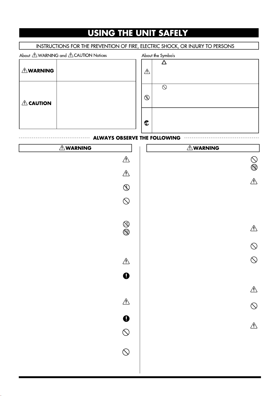
The symbol alerts the user to important instructions
or warnings.The specific meaning of the symbol is
determined by the design contained within the
triangle. In the case of the symbol at left, it is used for
general cautions, warnings, or alerts to danger.
The symbol alerts the user to items that must never
be carried out (are forbidden). The specific thing that
must not be done is indicated by the design contained
within the circle. In the case of the symbol at left, it
means that the unit must never be disassembled.
The ● symbol alerts the user to things that must be
carried out. The specific thing that must be done is
indicated by the design contained within the circle. In
the case of the symbol at left, it means that the powercord plug must be unplugged from the outlet.
011
• Do not allow any objects (e.g., flammable material, coins, pins); or
liquids of any kind (water, soft drinks, etc.) to penetrate the unit.
........................................................................................................................
012a
• Immediately turn the power off, remove the power cord from the
outlet, and request servicing by your retailer, the nearest Roland
Service Center, or an authorized Roland distributor, as listed on
the “Information” page when:
• The power-supply cord, or the plug has been damaged; or
• If smoke or unusual odor occurs
• Objects have fallen into, or liquid has been spilled onto the
unit; or
• The unit has been exposed to rain (or otherwise has become
wet); or
• The unit does not appear to operate normally or exhibits a
marked change in performance.
........................................................................................................................
013
• In households with small children, an adult should provide supervision until the child is capable of following all the rules essential
for the safe operation of the unit.
........................................................................................................................
014
• Protect the unit from strong impact.
(Do not drop it!)
........................................................................................................................
015
• Do not force the unit’s power-supply cord to share an outlet with
an unreasonable number of other devices. Be especially careful
when using extension cords—the total power used by all devices
you have connected to the extension cord’s outlet must never
exceed the power rating (watts/amperes) for the extension cord.
Excessive loads can cause the insulation on the cord to heat up
and eventually melt through.
........................................................................................................................
016
• Before using the unit in a foreign country, consult with your
retailer, the nearest Roland Service Center, or an authorized
Roland distributor, as listed on the “Information” page.
........................................................................................................................
023
• DO NOT play a CD-ROM disc on a conventional audio CD player.
The resulting sound may be of a level that could cause permanent
hearing loss. Damage to speakers or other system components
may result.
........................................................................................................................
026
• Do not put anything that contains water (e.g., flower vases) on
this unit. Also, avoid the use of insecticides, perfumes, alcohol,
nail polish, spray cans, etc., near the unit. Swiftly wipe away any
liquid that spills on the unit using a dry, soft cloth.
........................................................................................................................
3
Page 5
USING THE UNIT SAFELY
101a
• The unit should be located so that its location or position does not
interfere with its proper ventilation.
........................................................................................................................
102b
• Always grasp only the plug on the power-supply cord when
plugging into, or unplugging from, an outlet or this unit.
........................................................................................................................
103a
• At regular intervals, you should unplug the power plug and clean
it by using a dry cloth to wipe all dust and other accumulations
away from its prongs. Also, disconnect the power plug from the
power outlet whenever the unit is to remain unused for an
extended period of time. Any accumulation of dust between the
power plug and the power outlet can result in poor insulation and
lead to fire.
........................................................................................................................
104
• Try to prevent cords and cables from becoming entangled. Also,
all cords and cables should be placed so they are out of the reach
of children.
........................................................................................................................
106
• Never climb on top of, nor place heavy objects on the unit.
........................................................................................................................
107b
• Never handle the power cord or its plugs with wet hands when
plugging into, or unplugging from, an outlet or this unit.
........................................................................................................................
108a
• Before moving the unit, disconnect the power plug from the
outlet, and pull out all cords from external devices.
........................................................................................................................
109a
• Before cleaning the unit, turn off the power and unplug the power
cord from the outlet (p. 54).
........................................................................................................................
110a
• Whenever you suspect the possibility of lightning in your area,
pull the plug on the power cord out of the outlet.
........................................................................................................................
118c
• Keep any screws you may remove and the included screws in a
safe place out of children's reach, so there is no chance of them
being swallowed accidentally.
........................................................................................................................
120
• Always turn the phantom power off when connecting any device
other than condenser microphones that require phantom power.
You risk causing damage if you mistakenly supply phantom
power to dynamic microphones, audio playback devices, or other
devices that don’t require such power. Be sure to check the specifications of any microphone you intend to use by referring to the
manual that came with it.
(This instrument’s phantom power: 48 V DC, 10 mA Max)
........................................................................................................................
IMPORTANT NOTES
291b
In addition to the items listed under “IMPORTANT SAFETY INSTRUCTIONS” and “USING THE UNIT SAFELY” on pages 2–4, please read
and observe the following:
Power Supply
301
• Do not connect this unit to same electrical outlet that is being used by an
electrical appliance that is controlled by an inverter (such as a refrigerator,
washing machine, microwave oven, or air conditioner), or that contains a
motor. Depending on the way in which the electrical appliance is used,
power supply noise may cause this unit to malfunction or may produce
audible noise. If it is not practical to use a separate electrical outlet, connect
a power supply noise filter between this unit and the electrical outlet.
307
• Before connecting this unit to other devices, turn off the power to all units.
This will help prevent malfunctions and/or damage to speakers or other
devices.
308
• Although the LCD and LEDs are switched off when the POWER switch is
switched off, this does not mean that the unit has been completely disconnected from the source of power. If you need to turn off the power
completely, first turn off the POWER switch, then unplug the power cord
from the power outlet. For this reason, the outlet into which you choose to
connect the power cord’s plug should be one that is within easy reach and
readily accessible.
Placement
351
• Using the unit near power amplifiers (or other equipment containing large
power transformers) may induce hum. To alleviate the problem, change the
orientation of this unit; or move it farther away from the source of interference.
352a
• This device may interfere with radio and television reception. Do not use
this device in the vicinity of such receivers.
352b
• Noise may be produced if wireless communications devices, such as cell
phones, are operated in the vicinity of this unit. Such noise could occur
when receiving or initiating a call, or while conversing. Should you
experience such problems, you should relocate such wireless devices so
they are at a greater distance from this unit, or switch them off.
355b
• When moved from one location to another where the temperature and/or
humidity is very different, water droplets (condensation) may form inside
the unit. Damage or malfunction may result if you attempt to use the unit in
this condition. Therefore, before using the unit, you must allow it to stand
for several hours, until the condensation has completely evaporated.
Maintenance
401a
• For everyday cleaning wipe the unit with a soft, dry cloth or one that has
been slightly dampened with water. To remove stubborn dirt, use a cloth
impregnated with a mild, non-abrasive detergent. Afterwards, be sure to
wipe the unit thoroughly with a soft, dry cloth.
402
• Never use benzine, thinners, alcohol or solvents of any kind, to avoid the
possibility of discoloration and/or deformation.
Repairs and Data
452
• Please be aware that all data contained in the unit’s memory may be lost
when the unit is sent for repairs. Important data should always be backed
up on a memory card, or written down on paper (when possible). During
repairs, due care is taken to avoid the loss of data. However, in certain cases
(such as when circuitry related to memory itself is out of order), we regret
that it may not be possible to restore the data, and Roland assumes no
liability concerning such loss of data.
4
Page 6
USING THE UNIT SAFELY
Additional Precautions
• You cannot detach the V-Synth XT's rack-mounting hardware from the
main unit. Also, you must never loosen any screws other than the “rotation
lock hardware” (P.19). Doing so will cause malfunctions.
• Before you transport the V-Synth XT, you must install the included
“rotation lock hardware.” The unit may be damaged if you transport it
without the “rotation lock hardware” installed (p. 19).
551
• Please be aware that the contents of memory can be irretrievably lost as a
result of a malfunction, or the improper operation of the unit. To protect
yourself against the risk of loosing important data, we recommend that you
periodically save a backup copy of important data you have stored in the
unit’s memory on a memory card.
552
• Unfortunately, it may be impossible to restore the contents of data that was
stored in the unit's memory, on a memory card, or in another MIDI device
(e.g., a sequencer) once it has been lost. Roland Corporation assumes no
liability concerning such loss of data.
553
• Use a reasonable amount of care when using the unit’s buttons, sliders, or
other controls; and when using its jacks and connectors. Rough handling
can lead to malfunctions.
554
• Never strike or apply strong pressure to the display.
556
• When connecting / disconnecting all cables, grasp the connector itself—
never pull on the cable. This way you will avoid causing shorts, or damage
to the cable’s internal elements.
557
• A small amount of heat will radiate from the unit during normal operation.
558a
• To avoid disturbing your neighbors, try to keep the unit’s volume at
reasonable levels. You may prefer to use headphones, so you do not need to
be concerned about those around you (especially when it is late at night).
559a
• When you need to transport the unit, package it in the box (including
padding) that it came in, if possible. Otherwise, you will need to use equivalent packaging materials.
562
• Use a cable from Roland to make the connection. If using some other make
of connection cable, please note the following precautions.
• Some connection cables contain resistors. Do not use cables
that incorporate resistors for connecting to this unit. The use
of such cables can cause the sound level to be extremely low,
or impossible to hear. For information on cable specifications,
contact the manufacturer of the cable.
Compatibility of patches created on
an older version of V-Synth
•
Be aware that if patches created on a V-Synth with a system version
older than 2.0 (i.e., versions 1.00 through 1.51 of the system) use preset
PCM waves, those patches will not play correctly on version 2.0.
Before Using Cards
Using Memory Cards
704
• Carefully insert the DATA card all the way in—until it is firmly in place.
705
• Never touch the terminals of the memory card. Also, avoid getting the
terminals dirty.
708
• Memory cards are constructed using precision components; handle the
cards carefully, paying particular note to the following.
• To prevent damage to the cards from static electricity, be sure
to discharge any static electricity from your own body before
handling the cards.
• Do not touch or allow metal to come into contact with the
contact portion of the cards.
• Do not bend, drop, or subject cards to strong shock or
vibration.
• Do not keep cards in direct sunlight, in closed vehicles, or
other such locations (storage temperature: -25 to 85˚ C).
• Do not allow cards to become wet.
• Do not disassemble or modify the cards.
Handling CD-ROMs
801
• Avoid touching or scratching the shiny underside (encoded surface) of the
disc. Damaged or dirty CD-ROM discs may not be read properly. Keep your
discs clean using a commercially available CD cleaner.
Copyright
851
• Unauthorized recording, distribution, sale, lending, public performance,
broadcasting, or the like, in whole or in part, of a work (musical composition, video, broadcast, public performance, or the like) whose copyright is
held by a third party is prohibited by law.
852b
• When exchanging audio signals through a digital connection with an
external instrument, this unit can perform recording without being
subjected to some of the restrictions of the Serial Copy Management System
(SCMS). This is because the unit is intended solely for musical production,
and is designed not to be subject to restrictions as long as it is used to record
works (such as your own compositions) that do not infringe on the
copyrights of others. (SCMS is a feature that prohibits second-generation
and later copying through a digital connection. It is built into MD recorders
and other consumer digital-audio equipment as a copyright-protection
feature.)
853
• Do not use this unit for purposes that could infringe on a copyright held by
a third party. We assume no responsibility whatsoever with regard to any
infringements of third-party copyrights arising through your use of this
unit.
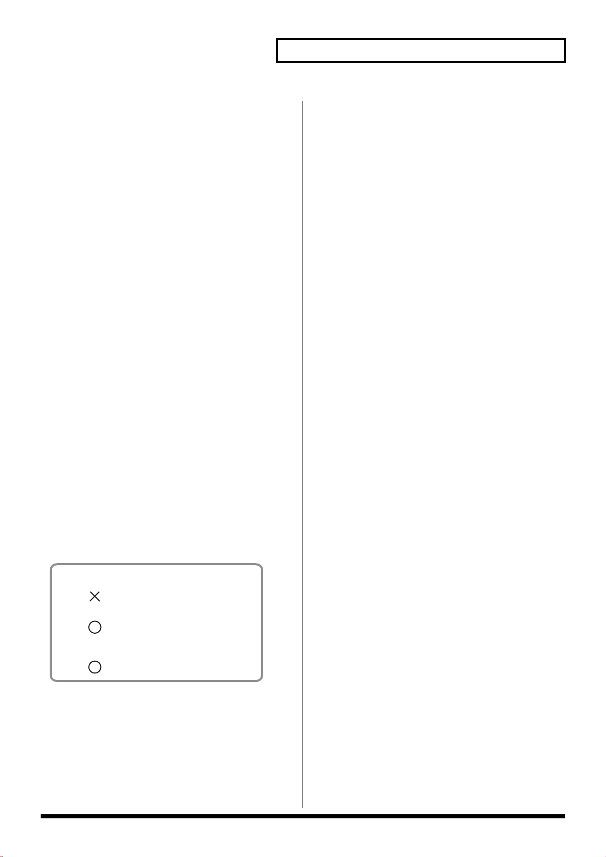
■Patches that use a PCM oscillator
Patches that use preset waves
Not compatible
Will NOT play correctly in version 2.0
Patches that use user waves
Upwardly compatible
Can be imported and played in version 2.0
■Patches that use an analog oscillator
■Patches that use an external input oscillator
Upwardly compatible
Can be imported and played in version 2.0
5
Page 7
How To Use This Manual
This owner’s manual is organized as follows.
For details on all the patches and waves that the V-Synth XT
contains, refer to the separate “Sound List.”
Quick Start (
This chapter offers a basic introduction to the V-Synth XT, and
provides simple, easy-to-understand explanations, allowing the
beginner to quickly experience many of the V-Synth XT’s exciting
features. As you read the Quick Start, we recommend actually
performing the described operations on your V-Synth XT. This’ll
help you understand most of what you need to know for basic
operations.
Reference (
p. 17)
p. 55)
Overview of the V-Synth XT
This explains the structure of the V-Synth XT, and basic operation.
Reading it is essential for understanding V-Synth XT operational
procedures.
Playing in Patch Mode
This explains how to play the V-Synth XT in Patch mode. Reading it
is essential for understanding V-Synth XT operational procedures.
Creating a Patch
This chapter explains how to create patches, and describes what the
patch parameters do and how they are composed. Read this chapter
when you wish to create patches.
Other Functions
This explains how to transmit data to an external MIDI device (Data
Transfer), and how to restore all data of the V-Synth XT to the
factory settings (Factory Reset). Read it as necessary.
Appendices (p. 149)
This chapter contains a troubleshooting section for use when the V-
Synth XT is not functioning as expected. There is also a list of
messages that you can refer to if an message appears on the display.
A list of parameters and a MIDI implementation chart are also
provided.
Notation Used in This Owner’s Manual
To make operation procedures easy to understand, the following
notation system is adopted:
Characters and graphics in square brackets [ ] indicate buttons and
knobs on the front panel. For example, [MODE] indicates the MODE
button, and [ ], [ ], [ ], and [ ] indicates the cursor
buttons.
Text or graphics enclosed in < > indicate objects in the screen (touch
screen) that can be touched using your finger. The manual will
instruct you to “touch” the object shown in the touch screen.
(p. **) refers to pages within the manual.
Below are the meanings of the symbols preceding certain sentences
in the text.
These are notes. Be sure to read them.
Creating a Rhythm Kit (Rhythm Mode)
This chapter explains how to create a Rhythm Kit.
Creating and Editing Samples (Sample
Mode)
This explains how to sample, and how to edit and encode samples.
Read this when you want to sample sounds.
Settings Common to All Modes (System
Mode)
This chapter describes how the System parameters that determine
the V-Synth XT’s operation environment work and how these
parameters are organized. Read it as necessary.
Disk-Related Functions (Disk Mode)
This chapter covers disk-related operations such as saving data to
disk and loading data from disk. Read it as necessary.
Transferring Data (USB Mode)
This explains how to connect the V-Synth XT to your computer, and
transfer data such as patches and waves. Read this as necessary.
These are reference memos. Read it as necessary.
These are hints for operating the V-Synth XT. Read it as
necessary.
These provide information from related reference pages. Read it
as necessary.
985
The display screens printed in this owner’s manual are based on
the factory settings. However, please be aware that in some cases
they may differ from the actual factory settings.
Please be aware that in the screen shots printed in this manual,
the patch names may differ from the factory settings.
Separate booklet:
V-Card owner's manual
The Roland “V-Card” series software VC-1 and VC-2 are
preinstalled in the V-Synth XT. For details on how to use the VC-1
“D-50” and VC-2 “Vocal Designer,” refer to the separate “V-Card
owner's manual.”
6
Page 8

Contents
How To Use This Manual........................................................................................... 6
Notation Used in This Owner’s Manual...................................................................................... 6
Main Features........................................................................................................... 12
Panel Descriptions................................................................................................... 14
Front Panel................................................................................................................................................. 14
Rear Panel.................................................................................................................................................. 16
Quick Start ........................................17
Getting Ready........................................................................................................... 18
Placing the V-Synth XT............................................................................................................................ 18
Connecting an Amp and Speaker System............................................................................................. 20
Turning On the Power ............................................................................................................................. 21
Starting up V-Card ...................................................................................................................................22
Adjusting the Display Contrast (LCD Contrast).................................................................................. 22
Installing the PC Card Protector ............................................................................................................23
Basic Touch Screen Operation............................................................................... 24
Enabling/Disabling the Beep Tone........................................................................................................ 24
Moving the Cursor ................................................................................................................................... 25
Editing a Value.......................................................................................................................................... 26
Using the numeric keys for input .......................................................................................................... 27
Try Out the Sounds.................................................................................................. 28
Selecting Patches and Playing Sounds .................................................................................................. 28
Playing a Patch on the V-Synth XT from an External MIDI Device (MIDI Keyboard).................. 29
Selecting Patches from the List............................................................................................................... 29
Selecting Favorite Patches (Patch Palette)............................................................................................. 30
Playing a drum set (Rhythm mode) ...................................................................................................... 31
Try Out the Various Performance Features........................................................... 32
Manipulating Sounds with the Time Trip Pad ....................................................................................32
Using Knobs to Modify the Sound in Realtime (E1–E8 knobs) ......................................................... 34
Playing Arpeggios (Arpeggiator)........................................................................................................... 36
Using steps to vary the sound (Multi Step Modulator)...................................................................... 38
Holding the notes you play (Key Hold)................................................................................................ 39
Creating a Patch....................................................................................................... 40
Creating a patch intuitively (Sound Shaper)........................................................................................ 40
Initializing Patch Settings........................................................................................................................ 42
Selecting a Structure Type....................................................................................................................... 43
Switching Each Section On/Off ............................................................................................................. 45
Setting Up the Oscillators (OSC1/2)...................................................................................................... 46
Mixing/Modulating Two Sounds (Mod)..............................................................................................47
Applying COSM Modeling to Oscillators (COSM1/2)....................................................................... 48
Shaping a Sound’s Volume Over Time (TVA)..................................................................................... 49
Adding the V-Synth XT Effects ..............................................................................................................50
Saving Patches You’ve Created.............................................................................................................. 51
Turning Off the Power............................................................................................................................. 54
7
Page 9

Contents
Reference ..........................................55
Overview of the V-Synth XT .................................................................................... 56
How the V-Synth XT Is Organized ........................................................................................................ 56
Basic Structure ............................................................................................................................... 56
Polyphony ...................................................................................................................................... 56
About Multitimbral Performance ...............................................................................................56
Memory...................................................................................................................................................... 57
Memory Structure ......................................................................................................................... 57
Basic Operation of the V-Synth XT ........................................................................................................ 58
Changing Operating Modes ([MODE]) .....................................................................................58
Playing in Patch Mode............................................................................................. 60
About the PATCH PLAY Screen............................................................................................................ 60
Displaying PATCH PLAY Screen............................................................................................... 60
Selecting a Patch .......................................................................................................................................60
Selecting Favorite Patches (Patch Palette) ................................................................................. 61
Selecting Patches by Category..................................................................................................... 61
Selecting Patches from the List.................................................................................................... 62
Playing Single Notes (Mono).................................................................................................................. 63
Creating Smooth Pitch Changes (Portamento) ....................................................................................63
Making Controller-related Settings (Control) ......................................................................................63
Playing Arpeggios (Arpeggiator)........................................................................................................... 64
Holding an Arpeggio.................................................................................................................... 64
Making Arpeggiator Settings ...................................................................................................... 65
Creating an Original Arpeggio Pattern (Pattern Edit)............................................................. 65
Using steps to vary the sound (Multi Step Modulator)...................................................................... 68
Applying Various Effects to the Sound................................................................................................. 69
Applying an Effect by Touching Your Finger to the Pad (Time Trip Pad)........................... 69
Applying an Effect by Turning a Knob (E1–E8 knobs) ........................................................... 70
Synchronizing Music and Video While You Play the V-Synth XT (V-LINK) .................................71
Enter V-LINK Mode ..................................................................................................................... 71
V-LINK Functions that the V-Synth XT Can Control and MIDI Messages.......................... 71
Creating a Patch....................................................................................................... 72
How to Make the Patch Settings ............................................................................................................72
Initializing Patch Settings (PATCH Init) ................................................................................... 73
Copying Patch Settings (PATCH Copy).................................................................................... 73
Naming a Patch (PATCH Name)........................................................................................................... 74
Assigning the Category of a Patch......................................................................................................... 74
Saving Patches (PATCH Write).............................................................................................................. 75
Auditioning the Save-Destination Patch (Compare) ............................................................... 76
Registering a Favorite Patch (Patch Palette) ............................................................................. 76
Deleting Patches (PATCH Delete) .........................................................................................................77
Creating a patch intuitively (Sound Shaper)........................................................................................ 77
Functions of Patch Parameters ...............................................................................................................79
Settings Common to the Entire Patch (Common) .................................................................... 79
Modifying Waveforms (OSC1/OSC2) ....................................................................................... 86
Mixing/Modulating Two Sounds (MOD)................................................................................. 93
Applying Various Effects to Each Note You Play (COSM1/COSM2) ..................................93
Adjusting the Volume and Pan (TVA)....................................................................................... 94
Making Envelope Settings ...........................................................................................................95
Making LFO Settings ....................................................................................................................96
Setting Effects for a Patch (Effect)............................................................................................... 97
Zone Settings (Zone) ................................................................................................................................99
Splitting the Keyboard to Play Different Sounds (Split) .........................................................99
Creating a Drum Patch (Drum)................................................................................................. 101
8
Page 10

Contents
Creating a Rhythm Kit (Rhythm Mode) ................................................................ 102
The concept of a Rhythm Kit ................................................................................................................102
Playing in Rhythm mode ...................................................................................................................... 102
Creating a Rhythm Kit........................................................................................................................... 103
Creating and Editing Samples (Sample Mode).................................................... 104
Sampling .................................................................................................................................................. 104
Settings Before You Sample (What Is a Template?) ...............................................................104
Sampling Procedure ................................................................................................................... 105
Resampling................................................................................................................................... 109
Setup Settings .............................................................................................................................. 109
Pre-Effect Settings .......................................................................................................................110
Metronome Settings.................................................................................................................... 111
Checking Sample Information.............................................................................................................. 112
Importing a Sample................................................................................................................................ 113
Editing a Sample..................................................................................................................................... 113
Common Procedure for Editing................................................................................................ 113
Editing the Specified Region of the Sample ............................................................................ 115
Loop Region Settings.................................................................................................................. 117
Original Tempo Setting .............................................................................................................. 118
Converting the Sample to V-Synth XT Data (Encode)...................................................................... 118
Selecting the Encoding Type .....................................................................................................119
Automatically Detecting Events ...............................................................................................120
Deleting and Adding Events .....................................................................................................120
Saving a Sample...................................................................................................................................... 121
Settings Common to All Modes (System Mode) .................................................122
How to Make the System Function Settings....................................................................................... 122
Saving the System Settings (Write)........................................................................................... 122
Initializing the System Settings (Init) ....................................................................................... 122
Functions of System Parameters ..........................................................................................................123
Settings Common to the Entire System (Common) ............................................................... 123
Controller Settings (Controller) ................................................................................................ 127
V-LINK Settings (V-LINK) ........................................................................................................ 129
Disk-Related Functions (Disk Mode).................................................................... 131
About Disk Utility .................................................................................................................................. 131
Basic Disk Utility Operations................................................................................................................ 131
Sorting the Files Displayed in the File List.............................................................................. 132
Loading a Project from Disk into the V-Synth XT (Load Project) ...................................................132
Saving Project on Disk (Save Project) .................................................................................................. 132
Delete Unneeded Files (Clean Project) ................................................................................................133
Importing Individual Patch or Wave Files (Import Files) ................................................................133
Initializing a Disk (Format)................................................................................................................... 134
Functions Related to Files and Folders (Tools) .................................................................................. 135
Copying Files/Folders (Copy) .................................................................................................. 135
Moving Files/Folders (Move) ...................................................................................................135
Deleting Files/Folders (Delete)................................................................................................. 136
Renaming a Files/Folders (Rename)................................................................................................... 137
Connecting to Your Computer via USB (USB Mode).......................................... 138
About USB Functions............................................................................................................................. 138
Driver Installation and Settings............................................................................................................ 138
Exchanging MIDI Messages with Your Computer (MIDI function) .............................................. 138
USB audio signal flow (USB audio device function)......................................................................... 138
Transferring Files to or from Your Computer (Storage Function) ..................................................139
Windows Users ........................................................................................................................... 139
Macintosh Users ..........................................................................................................................141
Examples of Using Storage Function................................................................................................... 143
9
Page 11

Contents
Using V-Synth Librarian ....................................................................................................................... 145
Features of V-Synth Librarian ...................................................................................................145
Installation.................................................................................................................................... 145
Other Functions .....................................................................................................146
Transmitting Data to an External MIDI Device (Data Transfer) .....................................................146
Reset to Default Factory Settings (Factory Reset).............................................................................. 147
Viewing Various Information (Info).................................................................................................... 147
Adjusting the Sensitivity of the Touch Screen (Calibration Mode) ................................................ 148
Adjusting the Sensitivity of the Touch Screen ........................................................................ 148
Appendices......................................149
Parameter List ........................................................................................................ 150
Patch Parameters .................................................................................................................................... 150
System Parameters .................................................................................................................................156
COSM List............................................................................................................... 159
COSM Parameters .................................................................................................................................. 159
Overdrive / Distortion............................................................................................................... 159
Wave Shape.................................................................................................................................. 159
Amp Simulator ............................................................................................................................ 160
Speaker Simulator ....................................................................................................................... 160
Resonator...................................................................................................................................... 160
1st order SideBandFilter............................................................................................................. 160
2nd order SideBandFilter........................................................................................................... 161
Comb Filter .................................................................................................................................. 161
Dual Filter..................................................................................................................................... 161
TVF ................................................................................................................................................162
Dynamic TVF............................................................................................................................... 162
Polyphonic Compressor............................................................................................................. 162
Polyphonic Limiter .....................................................................................................................162
Frequency Shifter ........................................................................................................................163
Lo-Fi Processor ............................................................................................................................163
TB Filter ........................................................................................................................................163
Effects List.............................................................................................................. 164
MFX Parameters .....................................................................................................................................164
01: Parametric EQ (Parametric Equalizer)............................................................................... 165
02: Graphic EQ (Graphic Equalizer)......................................................................................... 165
03: Resonant Filter....................................................................................................................... 165
04: Isolator and Filter .................................................................................................................. 166
05: Distortion / OD (Distortion / Overdrive)......................................................................... 166
06: Amp Simulator (Guitar Amp Simulator) .......................................................................... 167
07: Auto Wah ...............................................................................................................................168
08: Humanizer .............................................................................................................................168
09: Dynamic Processor (Stereo Dynamic Processor).............................................................. 169
10: Tape Echo Simulator............................................................................................................. 169
11: Stereo Delay ........................................................................................................................... 170
12: Multi Tap Delay..................................................................................................................... 171
13: Reverse Delay ........................................................................................................................171
14: Vocal Echo.............................................................................................................................. 172
15: Band Pass Delay .................................................................................................................... 172
16: Analog Delay -> Chorus ...................................................................................................... 173
17: Digital Chorus ....................................................................................................................... 173
18: Space Chorus ......................................................................................................................... 174
19: Hexa Chorus ..........................................................................................................................174
10
Page 12

Contents
20: Analog Flanger ...................................................................................................................... 174
21: BOSS Flanger ......................................................................................................................... 175
22: Step Flanger ........................................................................................................................... 175
23: Analog Phaser........................................................................................................................ 176
24: Digital Phaser......................................................................................................................... 176
25: Rotary...................................................................................................................................... 177
26: Tremolo/Auto Pan ............................................................................................................... 177
27: Stereo Pitch Shifter................................................................................................................ 178
28: OD/DS -> Cho/Flg (Overdrive/Distortion -> Chorus/Flanger).................................. 178
29: OD/DS -> Delay (Overdrive/Distortion -> Delay) ......................................................... 179
30: Cho/Flg -> Delay (Chorus/Flanger -> Delay) .................................................................179
31: Enh -> Cho/Flg (Enhancer -> Chorus/Flanger) .............................................................. 180
32: Enh -> Delay (Enhancer -> Delay)...................................................................................... 180
33: Vocal Multi............................................................................................................................. 181
34: Guitar Multi ...........................................................................................................................181
35: Bass Multi............................................................................................................................... 182
36: EP Multi.................................................................................................................................. 183
37: Keyboard Multi .....................................................................................................................183
38: Phonograph............................................................................................................................ 184
39: Radio Tuning .........................................................................................................................185
40: Bit Rate Converter................................................................................................................. 185
41: Pseudo Stereo......................................................................................................................... 185
Chorus Parameters................................................................................................................................. 186
Chorus Type................................................................................................................................. 186
Chorus Parameters...................................................................................................................... 186
Reverb Parameters ................................................................................................................................. 186
01: Room 1 .................................................................................................................................... 187
02: Room 2 .................................................................................................................................... 187
03: Room 3 .................................................................................................................................... 188
04: Hall 1....................................................................................................................................... 188
05: Hall 2....................................................................................................................................... 189
06: Hall 3....................................................................................................................................... 189
07: Garage..................................................................................................................................... 190
08: PLATE..................................................................................................................................... 190
09: Non-Linear ............................................................................................................................. 191
10: Delay ....................................................................................................................................... 191
Troubleshooting..................................................................................................... 193
Problems Related to the V-Synth XT ................................................................................................... 193
Problems Related to the USB Driver (Windows)............................................................................... 194
Problems Related to the USB Driver (Macintosh) .............................................................................196
Message List .......................................................................................................... 197
ERROR Screens ....................................................................................................................................... 197
WARNING Screens................................................................................................................................ 198
Message Boxes ........................................................................................................................................ 199
About MIDI .............................................................................................................. 200
About MIDI Connectors............................................................................................................. 200
MIDI Channels and Multi-timbral Sound Generators........................................................... 200
MIDI Implementation Chart.................................................................................... 201
Specifications......................................................................................................... 202
Index........................................................................................................................ 203
11
Page 13
Main Features
The V-Synth XT is a professional synthesizer with a sound generator section that represents a pooling of numerous proprietary Roland
technologies, allowing an extremely high level of musical expressive potential.
From acoustic-like sounds to lush pads, rhythmical grooves, and aggressive sounds that could not be produced by synthesizers of the past, the V-
Synth XT is able to create organic changes in the sound. Furthermore, the VC-1 and VC-2 “V-Card” series software expansions are preinstalled.
You can switch systems simply by pressing a single switch—there's no need for the bothersome routine of switching off the power, then switching
it back on again. Thanks to the inclusion of this software, the V-Synth XT can be used as two other, completely different products; as a “D-50” and
as a “Vocal Designer.”
Whether you're playing live on stage or producing music in the studio, and regardless of the musical styles in which you're working, the V-Synth
XT gives you usable and playable sounds that are available nowhere else.
■
The V-Synth sound engine,
producing utterly unique sounds
●
The sound generator section consists of a PCM oscillator with
VariPhrase capability, high-quality analog modeling oscillators,
powerful modulators, and COSM processors equipped with
sideband filters. You can specify how these sections are
connected simply by selecting a structure. By combining these
sections, each of which delivers powerful functionality, you can
create completely new sounds, which could not be produced on
any previous synthesizer.
●
Each of the two oscillators can function as one of three types:
PCM (VariPhrase), analog modeling, and external input.
Dedicated envelopes are provided for the principal parameters
of each oscillator. Even when using the oscillators alone, you can
apply a wide range of time-based changes.
●
The PCM oscillators utilize Roland's proprietary VariPhrase
technology. In a revolutionary breakthrough in comparison to
conventional waveform playback, VariPhrase allows the pitch,
time, and formant of the audio material to be varied with
complete independence in real time, while maintaining high
audio quality. This transforms a PCM waveform into “elastic
audio,” which you can freely stretch like a rubber band in the
desired direction and create organic-sounding changes.
●
The analog modeling oscillators are packed with high-quality
waveforms, such as the “Super Saw,” which is just what you
need for thick detuned textures; and a feedback oscillator, which
produces a dramatically varying lead sound—all together giving
you a total of fourteen waveforms to stimulate your musical
creativity.
●
The oscillator output can be processed by Roland's proprietary
COSM processors. Going far beyond the filter functionality seen
on typical synthesizers, these implement a wide range of
processes. There are a total of 16 types, including TVF, guitar
amp modeling, Lo-Fi processor, a sideband filter, which imparts
a sense of playable pitch to noise or a phrase, and a resonator,
which adds the body resonances of an instrument. You can also
apply a COSM processor to an external audio input and use the
V-Synth XT as a filter bank.
■
Sound Shaper function allows
intuitive sound creation
●
V-Synth XT features a Sound Shaper function, which liberates
the musician from dealing with an overwhelming number of
edit parameters. Simply choose the desired sound template from
the list, and the parameters that are effective for that template
will be selected and available for your control. You'll be able to
obtain the desired variations easily by operating a few knobs or
buttons to edit exactly what you need, just like a professional
sound designer.
■
Unique and useful patches
●
All sounds can be rewritten by the user down to the level of the
source waves. You can sample directly into the V-Synth XT, or import
WAV/AIFF files from external devices, making this is an ideal
instrument for the professional who insists on absolute originality.
●
V-Synth XT provides a Rhythm mode screen, which lets you
assign different V-Synth sounds to each note of the keyboard.
This means that you can use the synth sound generator as a
rhythm kit to play many types of sound from the keyboard.
Since the sound assigned to each key is a fully editable V-Synth
sound, you can have anything from an analog kick to VariPhrase
rhythm loops available for immediate playing.
■
The power to make bold timebased changes in sound
●
V-Synth XT provides a multi-step modulator, which lets you
choose four parameters from a broad range of choices, and
simultaneously modulate these parameters by completely
different ascending or descending patterns. You can use the panel
knobs to freely program the ascending or descending patterns,
and you can even turn Smoothing on and use this as an LFO.
●
VariPhrase waves can be freely controlled using the Time Trip
function. By stroking the Time Trip pad in a circular motion, you
can halt the progress of the waveform while the sound is still
being heard, and then play that sound from the keyboard as the
desired pitches. It's also easy to create distinctive effects such as
manually controlling the progression of break-beats.
●
All of the various functions that control time-based change can
be synchronized to the tempo. VariPhrase, the LFO and
envelope of each section, the programmable arpeggiator, the
multi-step modulator, and the effects can all be controlled by the
master tempo.
12
Page 14
■
What is VariPhrase?
VariPhrase has the following advantages:
1 Capable of changing the pitch, rate of time expansion/
compression and voice characteristics (formant) on a real-
time basis.
2 Allows easy synchronization to tempo and pitch.
3 A single sample covers an extended range of keys compared
to conventional digital samplers.
4 Retains sound quality, while implementing the above three
advantages.
VariPhrase overcomes many problems that conventional
samplers and digital recorders have with audio phrases.
Typical issues with Digital Samplers and Digital recorders
• Changing tempo affects Pitch.
• Changing the pitch of phrases affects tempo and formant of
the sound.
• Limited control of audio phrases. You cannot adjust a
partial section of a sound in real-time.
• Most samplers require multiple samples over limited key
ranges for realistic playback of a sound.
• Samples of the same tempo must be available for
performing chords, otherwise the notes of the chord will be
out of sync.
• Pitch or tempo changes on Digital samplers tends to
degrade audio quality.
VariPhrase solves all of these problems.
Hardware that meets the
demands of the professional
●
A unique design allows the V-Synth XT to be placed in a variety
of locations; both table-top and rack-mounted use are possible.
The design not only looks good, but is also highly practical.
●
The V-Synth XT features a large color touch-screen, which
provides a sophisticated user interface and guarantees easy
editing of the displayed parameters. There are also eight editing
knobs, which give you an “analog-feel” editing experience, and
which can also be used as a general-purpose MIDI control
surface.
●
Both optical and coaxial digital audio jacks are provided. The
output supports sample rates of 44.1 kHz, 48 kHz, and 96 kHz.
The main out allows balanced output via TRS phone plugs.
●
The front panel provides a mic input jack, which supports both
XLR connectors and phone plugs. Phantom power can be
supplied, and you can switch to high-impedance input,
accommodating a variety of input sources from studio mics to
electric guitars.
●
The USB connector supports file transfer, MIDI communication,
and audio streaming. A wide variety of data can be easily
backed up to your computer via a USB connection, and you can
even use the V-Synth XT as a USB audio converter for a broad
range of applications.
●
You can also store large amount of data using the PC card slot.
Commercially available PC card adaptors allow you to use
CompactFlash or SmartMedia cards.
Main Features
→
VC-2 "Vocal Designer" transforms the V-Synth XT into a
cutting-edge vocal modeling processor. By playing a
keyboard while you speak into the mic, you can create
beautiful and clearly intelligible human choruses as well as
many other vocal-type sounds with unprecedented quality.
For details on using VC-2 “Vocal Designer,” refer to the separate
“V-Card owner's manual.”
■
“V-Card” series expansions are
preinstalled
●
The V-Synth XT comes with the VC-1 and VC-2 titles from
Roland's “V-Card” software series preinstalled. Without having
to cycle power to the unit, you can simply press a single switch
to transform the V-Synth XT into a completely different product
(p. 22).
→
VC-1 "D-50" transforms the V-Synth XT into a sound module
that's equivalent to the Roland D-50 (a classic digital
synthesizer that was released in 1987). Not just the preset
patches, but every bit of functionality has been faithfully
reproduced, giving you that distinctive D-50 sound with the
stability of modern hardware.
For details on using VC-1 “D-50,” refer to the separate “V-Card
owner's manual.”
13
Page 15
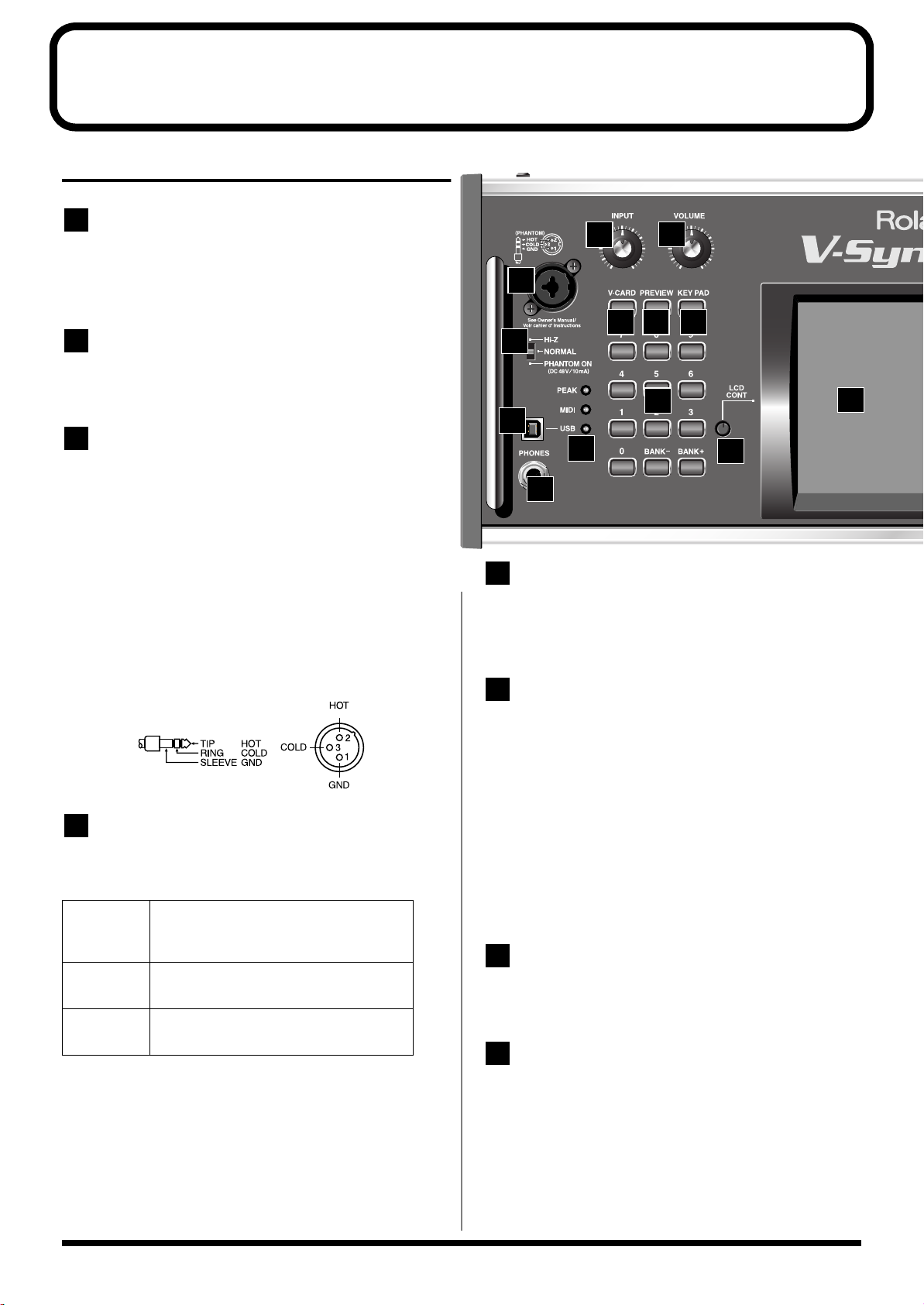
Panel Descriptions
5
6
7
8
Front Panel
1
INPUT
Adjusts the volume of the signal input through the MIC jacks on the
front panel. → (p. 106)
* This does not affect the rear panel INPUT jacks.
2
VOLUME
Adjusts the overall volume that is output from the MAIN OUT jacks
and PHONES jack.→ (p. 21)
3
MIC Jack
This is a mic jack for analog audio signal input.
It accommodates either XLR type or phone type plugs.
XLR type connections can provide 48V phantom power, allowing
you to connect condenser mics that require phantom power. In this
case, turn the mic switch to “PHANTOM ON.”
* The audio signal received via the MIC jack is switched on/off by the
MIC Jack Switch
922
* This instrument is equipped with balanced (XLR/TRS) type jacks.
Wiring diagrams for these jacks are shown below. Make connections
after first checking the wiring diagrams of other equipment you intend
to connect.
fig.XLR/TRSJack
(p. 126).
1
2
3
8
9 10
4
11
13
5
6
12
7
USB Connector
This is a USB connector. You can connect it to your personal computer
to send or receive files and MIDI messages (p. 138).Audio streaming
is also supported.
4
MIC Switch
This setting specifies the impedance and phantom power supply for
the mic jack.
Hi-Z
NORMAL
PHANTOM ONChoose this setting if you need to supply
* The MIC switch does not affect the rear panel INPUT jacks.
* Always turn the phantom power off when connecting any device other
than condenser microphones that require phantom power. You risk
causing damage if you mistakenly supply phantom power to dynamic
microphones, audio playback devices, or other devices that don’t require
such power. Be sure to check the specifications of any microphone you
intend to use by referring to the manual that came with it.
(This instrument’s phantom power: 48 V DC, 10 mA Max)
Choose the high impedance (Hi-Z) setting if
you've connected a high-impedance device
such as a guitar or bass to the phone-type input jack.
Choose the NORMAL setting if you've connected a low impedance device such as a mic
to the phone-type input jack.
phantom power to a mic connected to the
XLR-type input jack.
[PEAK] (Peak Indicator)
This will light when the input volume is too high.
* This responds to either the front panel MIC jack or the rear panel
INPUT jacks.
[MIDI] (MIDI indicator)
This will light when a MIDI message is received.
[USB] (USB indicator)
This will light when the V-Synth XT is connected via USB.
PHONES Jack
This is the jack for connecting headphones (sold separately).
→
(p. 20)
V-CARD Button
The Roland “V-Card” series software VC-1 and VC-2 are
preinstalled in the V-Synth XT. You can switch between V-Synth/
VC-1/VC-2 functionality simply by pressing the V-Card button (p.
22).
14
Page 16
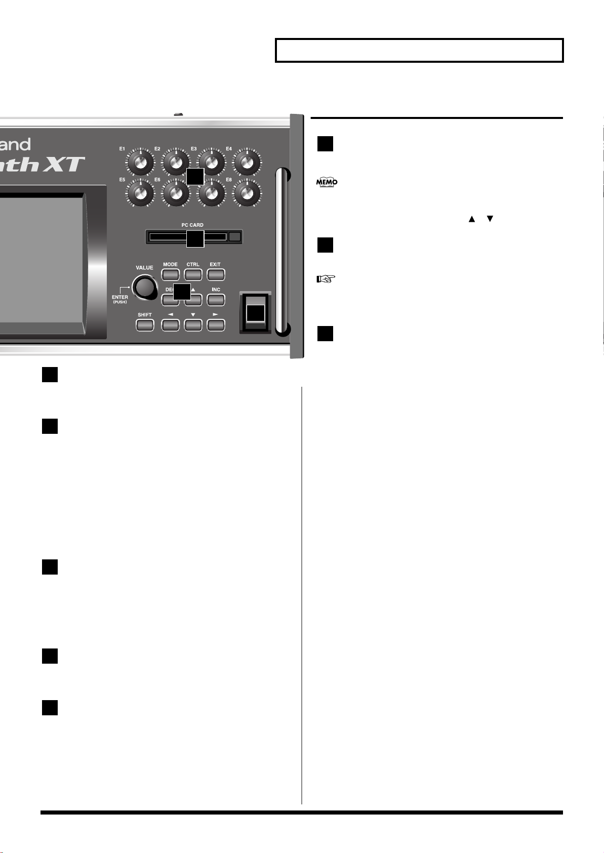
10
14
15
16
14
Panel Descriptions
E1–E8 knobs
These knobs control the on-screen parameters in real time (p. 34).
The parameters that are controlled by these knobs can be
p. 60
switched in the PATCH PLAY screen (
[SHIFT] key and using the up/down [ ][ ] cursor buttons.
) by holding down the
15
16
POWER
17
9
PREVIEW Button
Use this button to audition the patch.
KEY PAD Button
This button switches the function of the numeric keypad.
When lit:
• The numeric keypad will function as input keys.
→
Using the numeric keys for input
When unlit:
• The numeric keypad will function as a Patch Palette which lets
you select your favorite patches.
→
Selecting Favorite Patches (Patch Palette)
(p. 27)
(p. 61)
PC CARD Slot
A memory card can be inserted here.
For details on installing the included PC card protector, refer to
p. 23.
VALUE Dial
This is used to modify values. If you hold down [SHIFT] as you turn
the VALUE dial, the value will change in greater increments.
→
(p. 26)
Press the VALUE dial to perform the function of the ENTER button.
When the cursor is at an input location, you can press [ENTER]
(VALUE dial) and use the numeric keys to enter a numeric value (p.
27).
[SHIFT]
This button is used in conjunction with other buttons to execute
various functions.
[MODE]
Opens the Mode Menu window.
11
Numeric Key
When the cursor is at an input location, you can use the numeric
keypad to input parameter values (p. 27).
The keypad can also function as a Patch Palette that lets you select
your favorite patches (p. 61).
12
LCD CONT (LCD CONTRAST) Knob
Adjusts the display contrast. → (p. 22)
13
Display
This displays information regarding the operation you are
performing.
[CTRL]
This accesses the Control screen (p. 63). In the Control screen you use
the “Time Trip” function (p. 69) which lets you apply various effects
to the sound by touching the display. Additionally, this is also used
for the External Control function (p. 63), which lets you use the E1–
E8 knobs to control an external MIDI device; for the V-LINK
function (p. 71), which lets you control a video device; and for
switching the Arpeggio function on/off (p. 64).
[EXIT]
Return to the PLAY screen, or close the currently open window. In
some screens, this causes the currently executing function to be aborted.
[DEC], [INC]
This is used to modify values. If you keep on holding down one
button while pressing the other, the value change accelerates. If you
press one of these buttons while holding down [SHIFT], the value
will change in bigger increments. → (p. 26)
15
Page 17
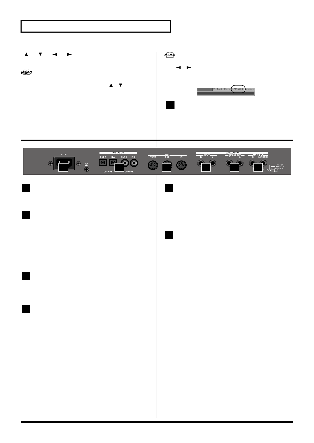
Panel Descriptions
17
5
6
[ ], [ ], [ ], [ ] (Cursor Buttons)
Moves the cursor location up/down/left/right. → (p. 25)
In the PATCH PLAY screen (p. 60), you can hold down the
[SHIFT] key and use the cursor up/down [ ][ ] keys to alter
the function of the E1–E8 knobs.
Rear Panel
fig.00-02
1 2 3 4 5 6
By holding down the [SHIFT] key and using the cursor left/right
([ ][ ]) keys you can switch the zone displayed in the
upper right of the PATCH PLAY screen or EDIT screen (p. 99).
POWER Switch
Press to turn the power on/off. → (p. 21, p. 54)
1
AC Inlet
Connect the included power cord to this inlet.
2
DIGITAL AUDIO INTERFACE
Connector (OPTICAL IN/OUT, COAXIAL
IN/OUT)
(conforming to IEC60958).
These connectors input/output a digital audio signal (stereo). The
output signal is identical to the signal that is output from the MAIN
OUT jacks.
3
MIDI Connectors (IN, OUT, THRU)
These connectors can be connected to other MIDI devices to receive
and transmit MIDI messages.
4
INPUT Jacks (L, R)
An external audio source such as a CD player can be connected to
these jacks for sampling or external input.
* The audio signal received via the INPUT jacks can be switched on/off
by the
INPUT Jack Switch
* * The gain of the audio signal received via the INPUT jacks is adjusted
by the
INPUT Jack Gain
(p. 126).
(p. 126).
DIRECT OUT Jacks (L, R)
(1/4 inch phone type)
This jack is a stereo output of the sound unprocessed by onboard
effects. An external effects processor or other devices can be
connected to these jacks.
MAIN OUT Jacks (L (MONO), R)
(1/4 inch TRS phone type)
These jacks output the audio signal to the connected mixer/amplifier
system in stereo. For mono output, use the L jack.
→
(p. 20)
16
Page 18

Quick Start
17
Page 19
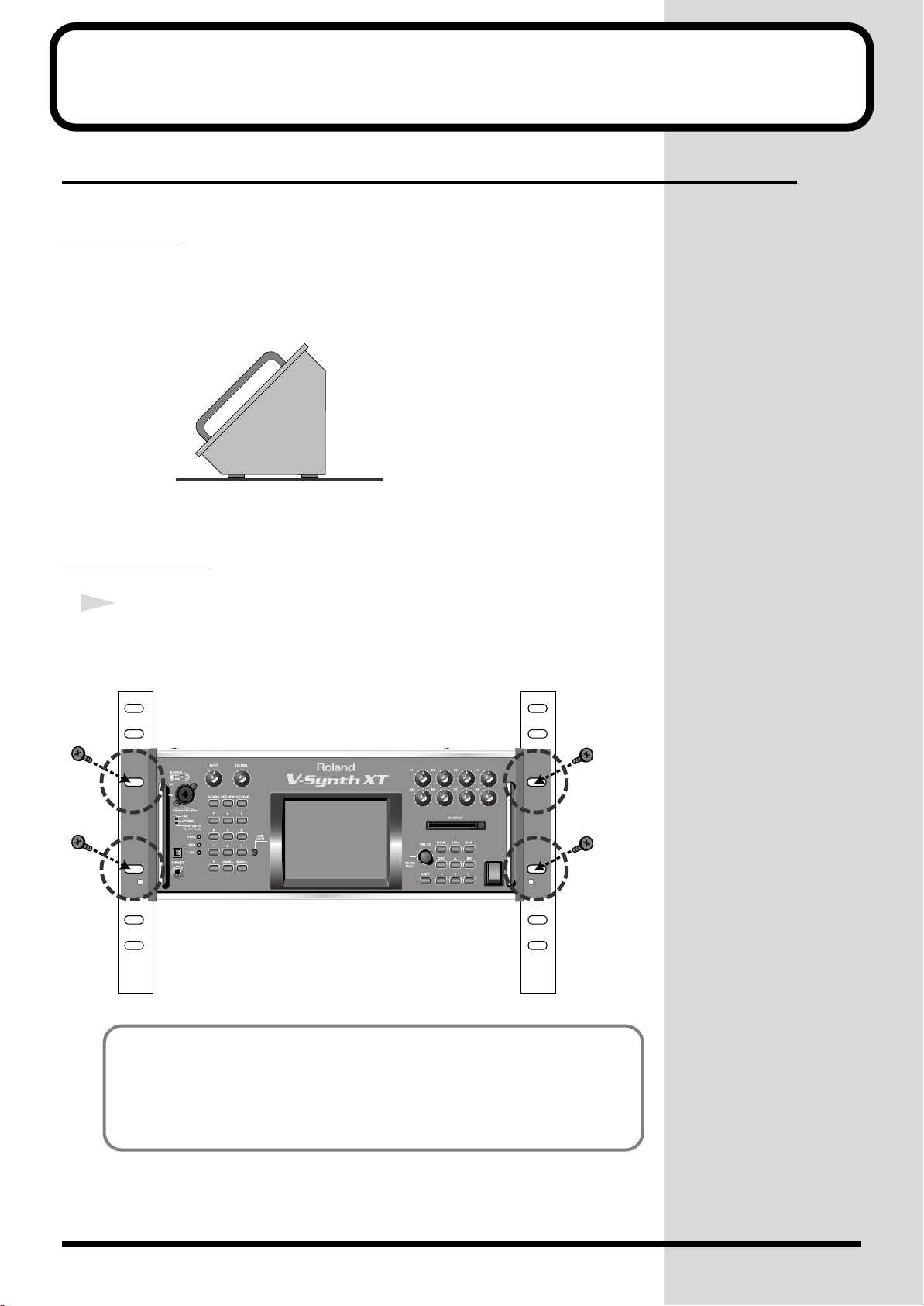
Getting Ready
Placing the V-Synth XT
The V-Synth XT's unique design lets you use it either on a table or in a rack.
Table-top use
Place the V-Synth XT as shown.
Rack-mount use
1
Install the V-Synth XT securely in a rack.
Use screws (sold separately) to mount the V-Synth XT securely in your rack (four
locations).
POWER
18
You cannot detach the V-Synth XT's rack-mounting
hardware from the main unit. Also, you must never
loosen any screws other than the “rotation lock
hardware.” Doing so will cause malfunctions.
Page 20
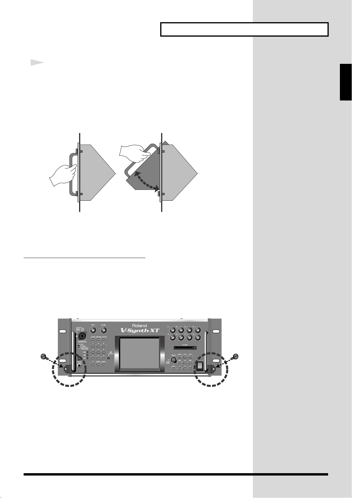
Getting Ready
2
You can change the angle of the V-Synth XT while it is mounted in a
rack.
Make sure that the V-Synth XT is securely installed in your rack. Then
firmly grasp both of the front panel handles, and pivot it toward
yourself until you hear a click.
To return the unit to its normal angle, push the handles inward until
you hear the click.
* You must perform this operation with the V-Synth XT installed in a rack.
* Some space above the V-Synth XT is required in order to use this rotating capability.
If equipment is installed in your rack directly above the V-Synth XT, you won't be able to
perform this operation.
Quick Start
Installing the rotation-lock hardware
Before you transport the V-Synth XT, you must install the included “rotation lock
hardware.” The unit may be damaged if you transport it without the “rotation lock
hardware” installed.
Use screws to fasten the “rotation lock hardware” as shown in the following
illustration.
POWER
19
Page 21
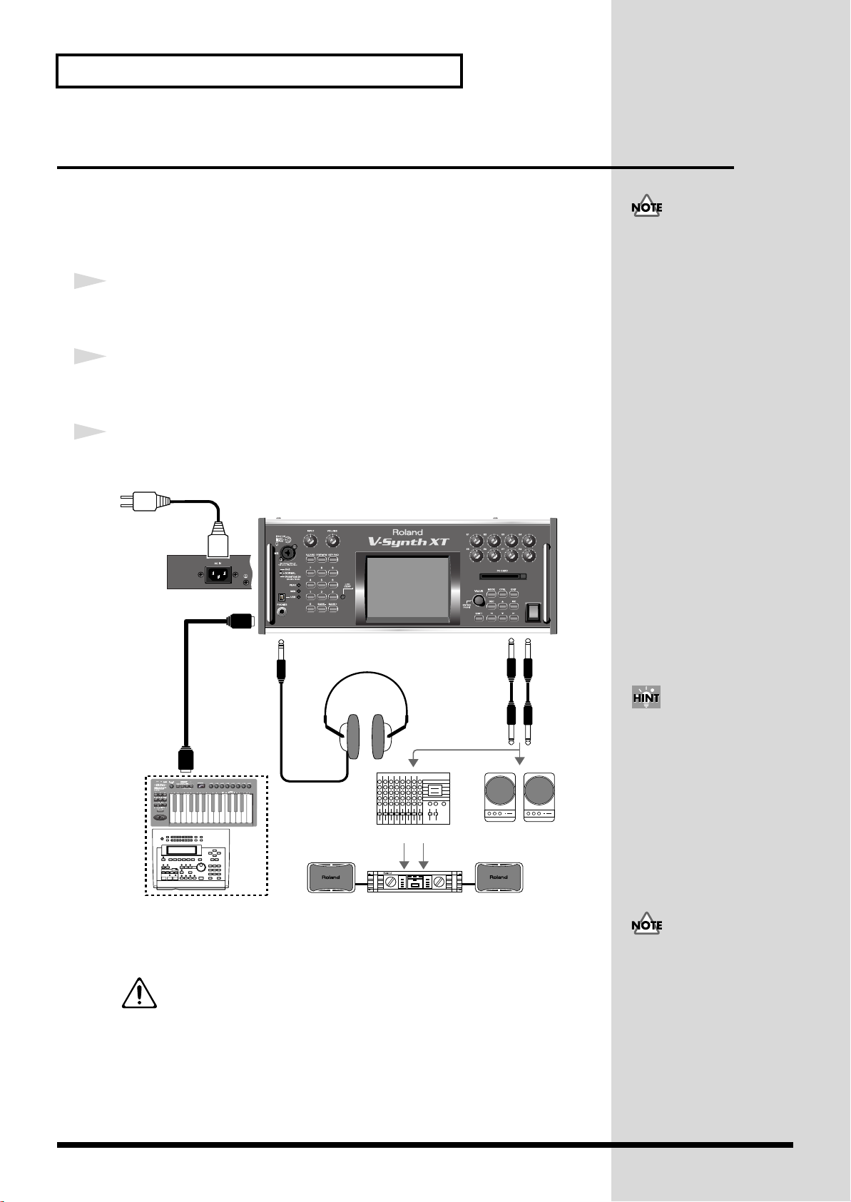
Getting Ready
V-Synth XT
Rear Panel
Monitor speakers
(powered)
Power amp
Mixer etc.
Stereo headphones
to Power outlet
V-Synth XT
PHONES MAIN OUT
MIDI IN
MIDI OUT
POWER
External MIDI device
(MIDI Keyboard, Sequencer, etc.)
Connecting an Amp and Speaker System
Since the V-Synth XT contains no amplifier or speakers, you’ll need to connect it to
audio equipment such as a keyboard amplifier, monitor speaker system or home
stereo, or use headphones to hear its sound.
Here we will explain example connections that use mainly the MAIN OUT jacks.
921
1
Before hooking anything up, make sure that the power on all of your
gear is turned OFF.
2
Connect one end of the supplied power cable to the V-Synth XT, and
the other end to a power outlet.
3
Connect the V-Synth XT to your amp/speaker system.
fig.Q-01.e
To prevent malfunction and/
or damage to speakers or other
devices, always turn down the
volume, and turn off the
power on all devices before
making any connections.
add
Use audio cables to connect audio equipment such as an amp or speakers. If you’re
using headphones, plug them into the PHONES jack.
*The unit should be connected to a power source only of the type marked on the rear
panel of the unit.
For details on the power consumption, refer to
For details on the settings you need when connecting the VSynth XT to your computer, refer to “
Computer via USB (USB Mode)
.
p. 202
Connecting to Your
”(p. 138)
In order to fully experience the
V-Synth XT’s sound, we
recommend using a stereo
amp/speaker system. If you’re
using a mono system,
however, make your
connections to the V-Synth
XT’s MAIN OUT jack L
(MONO).
Audio cables are not included
with the V-Synth XT. You’ll
need to provide them.
20
Page 22
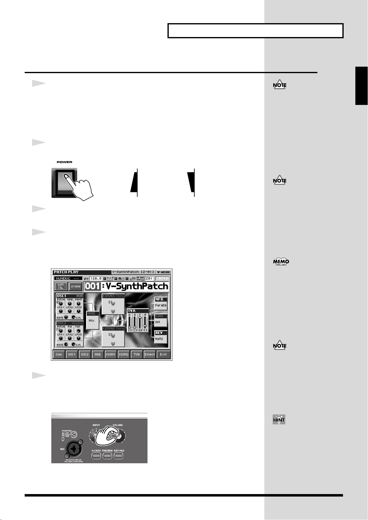
Getting Ready
b
While the V-Synth XT is
starting up, the display will
indicate “Processing...”
Turning On the Power
941
1
Before turning on the V-Synth XT’s power, consider these two
questions:
• Are all peripheral devices connected correctly?
• Have the volume controls of the V-Synth XT and all connected audio devices
been turned to their lowest settings?
2
Turn on the POWER switch located on the front panel of the V-Synth XT.
fig.Q-02.e
ON OFF
942
3
Turn on the power for any connected amplifiers or speakers.
4
Wait for the V-Synth XT to start up. When it has started up normally, a
screen like the following will appear.
* When you turn on the power, the V-Card that was most recently started will start up (p. 22).
fig.Q-02a_60
Quick Start
Once the connections have
een completed (p. 18), turn on
power to your various devices
in the order specified. By
turning on devices in the
wrong order, you risk causing
malfunctions and/or damage
to speakers and other devices.
This unit is equipped with a
protection circuit. A brief
interval (a few seconds) after
power up is required before
the unit will operate normally.
5
Set the volume for your connected amplifier and speakers. While
playing the external MIDI keyboard, gradually raise the V-Synth XT’s
volume slider to the desired listening level.
fig.Q-03
Be careful not to set your
listening volume too high to
avoid damage to your amp/
speaker system or your
hearing.
In order to obtain the best
audio quality from the V-Synth
XT, we recommend that you
set the V-Synth XT’s volume to
the maximum position, and
adjust the volume
appropriately on your amp or
speaker system.
21
Page 23
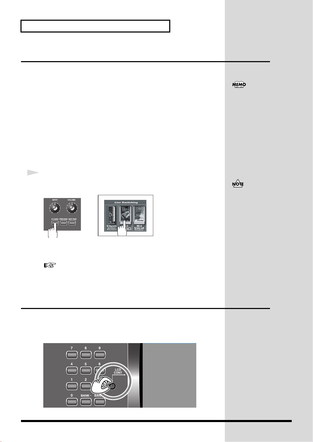
Getting Ready
When you start up V-Card
operation, any data that you
were editing will be lost. If
you've edited patches or
system settings, be sure to save
them first.
→“Saving Patches (PATCH
Write) ”(p. 75)
→“Saving the System
Settings (Write) ”(p. 122)
Starting up V-Card
You can press the [V-CARD] button to switch between V-Synth/VC-1/VC-2.
The Roland “V-Card” series VC-1 and VC-2 software is preinstalled in the V-Synth
XT. By pressing a single switch, you can change between these functions without
having to restart the unit, and use the V-Synth XT as a completely different product.
VC-1 “D-50” transforms the V-Synth XT into a sound module that's
equivalent to the Roland D-50 (a classic digital synthesizer that was released
in 1987). Not just the preset patches, but every bit of functionality has been
faithfully reproduced, giving you that distinctive D-50 sound with the
stability of modern hardware.
VC-2 “Vocal Designer” transforms the V-Synth XT into a cutting-edge vocal
modeling processor. By playing a keyboard while you speak into the mic, you
can create beautiful and clearly intelligible human choruses as well as many
other vocal-type sounds with unprecedented quality.
1
When the V-Synth XT has started up, press the [V-CARD] button, and
in the screen that appears, touch the V-Card that you want to use.
When you turn on the power,
the V-Card that was most
recently started will start up.
The V-Card startup screen will appear.
* By holding down the [V-CARD] button while you turn on the power, you can take a shortcut
to the above screen when the V-Synth XT starts up.
Adjusting the Display Contrast (LCD Contrast)
The characters in the display may be difficult to view immediately after turning on
the V-Synth XT’s power or after extended use. Your viewing angle or the current
lighting conditions can also affect the appearance of the display. In such situations,
you can turn the LCD CONT knob to adjust the contrast of the display.
fig.Q-04
For details on how to use the VC-1 “D-50” and VC-2
“Vocal Designer,” refer to the separate “V-Card owner's
manual.”
22
Page 24
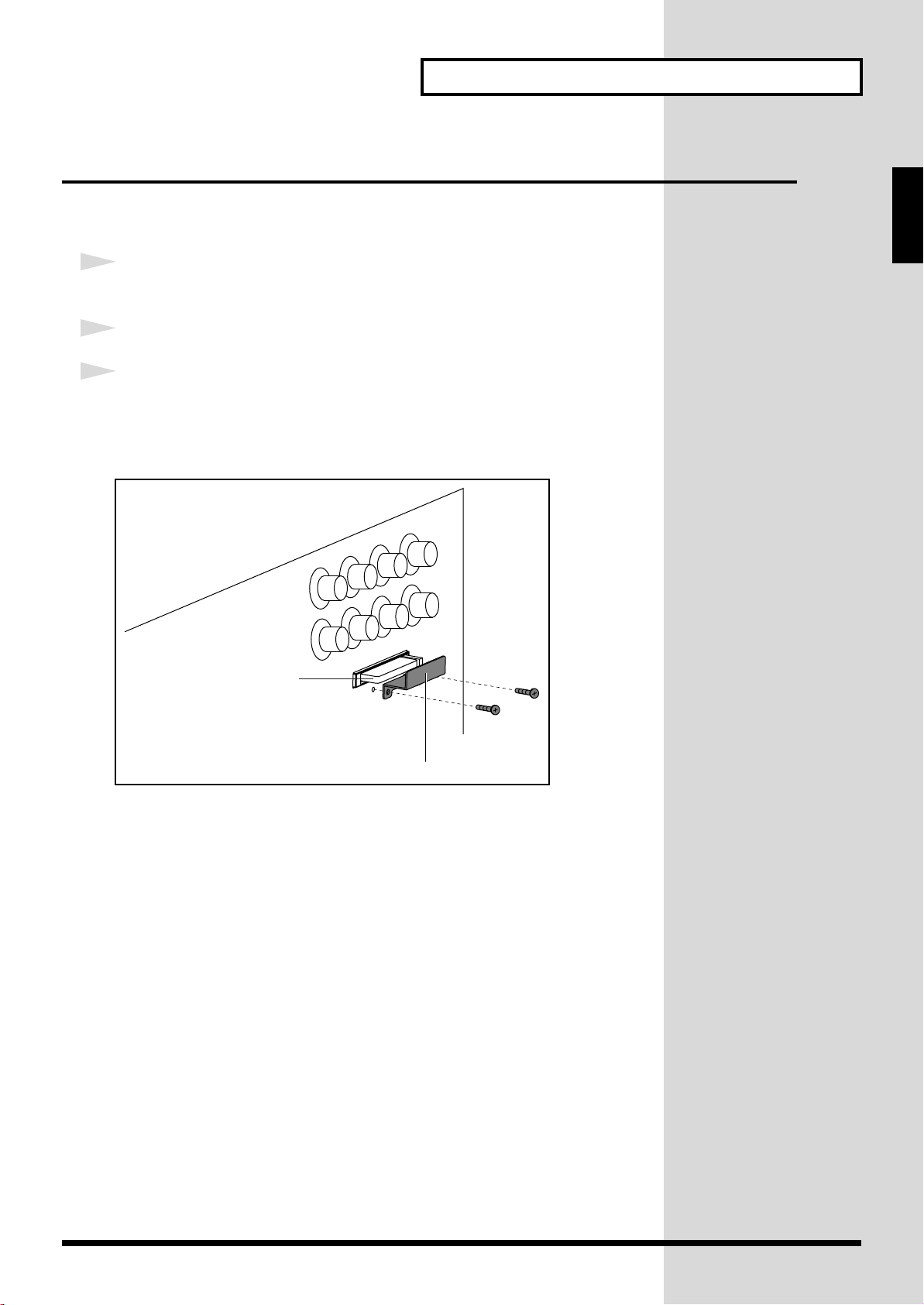
Getting Ready
PC card protector
Memory card
front panel
Installing the PC Card Protector
The V-Synth XT provides a PC card protector to prevent theft of the memory card.
To install the PC card protector, use the following procedure.
1
Use a screwdriver to remove both of the screws from the bottom side
of the PC CARD slot.
2
Insert the PC card into the PC CARD card slot.
3
Use the screws to fasten the PC card protector as shown below.
930
931
* Never insert or remove a memory card while this unit’s power is on. Doing so may corrupt
the unit’s data or the data on the memory card.
* Carefully insert the memory card all the way in—until it is firmly in place.
Quick Start
23
Page 25
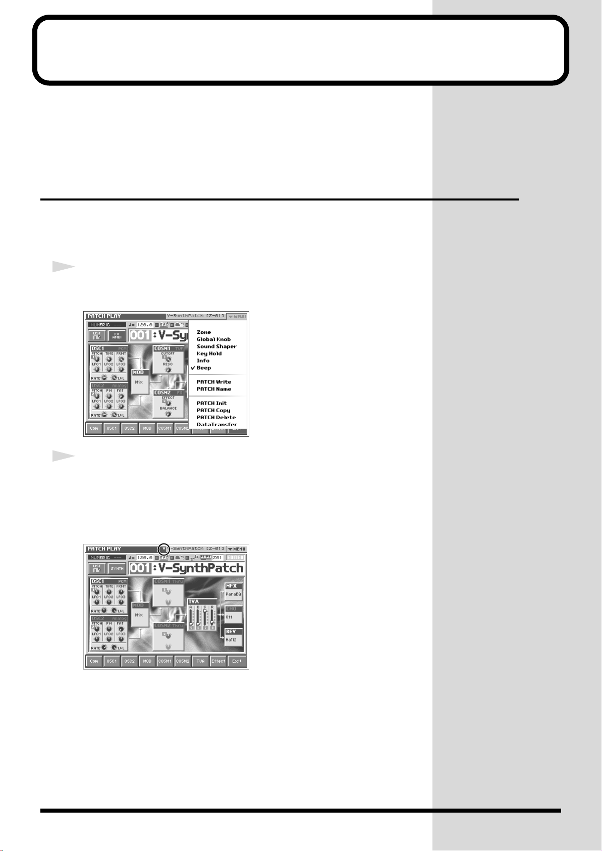
Basic Touch Screen Operation
The V-Synth XT features a touch screen. The touch screen lets you perform a variety
of operations by lightly touching the screen.
* The touch screen responds to a light touch. Pressing the touch screen with too much force, or
with a hard object, may damage it. Be careful not to apply excessive force, and touch it only
with your finger.
Enabling/Disabling the Beep Tone
You can specify whether or not a beep tone will be heard when you touch a valid
point on the touch screen.
* At the factory setting, the beep tone will be sounded.
1
In the upper right of the screen, touch <▼ MENU>.
A pulldown menu appears.
fig.01-05_50
fig.01-06
2
In the pulldown menu, touch <Beep> to add a check mark (✔).
With this setting, the beep tone will be heard. If you perform the same procedure
once again, the check mark will be cleared and the beep tone will no longer be heard.
* If you have turned off the beep tone, a “∇” appears in the title area at the top of the screen
when you touch a valid point on the touch screen.
24
Page 26
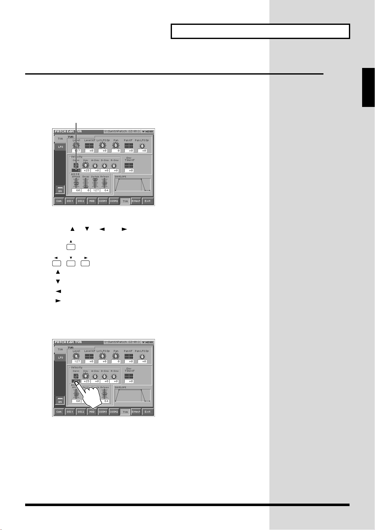
Basic Touch Screen Operation
Moving the Cursor
A single screen or window displays multiple parameters or items for selection. To
edit a parameter’s value, move the cursor to the value. The cursor is a blue rectangle,
and the parameter value or item you select with the cursor is highlighted (displayed
in inverted colors).
fig.01-07.e
Cursor
Cursor Buttons
Press [ ], [ ], [ ], or [ ] (the cursor buttons) to move the cursor.
fig.01-08
Quick Start
[ ]: moves the cursor up.
[ ]: moves the cursor down.
[ ]: moves the cursor to the left.
[ ]: moves the cursor to the right.
Touch Screen
Directly touch a parameter value to move the cursor.
fig.01-09
25
Page 27
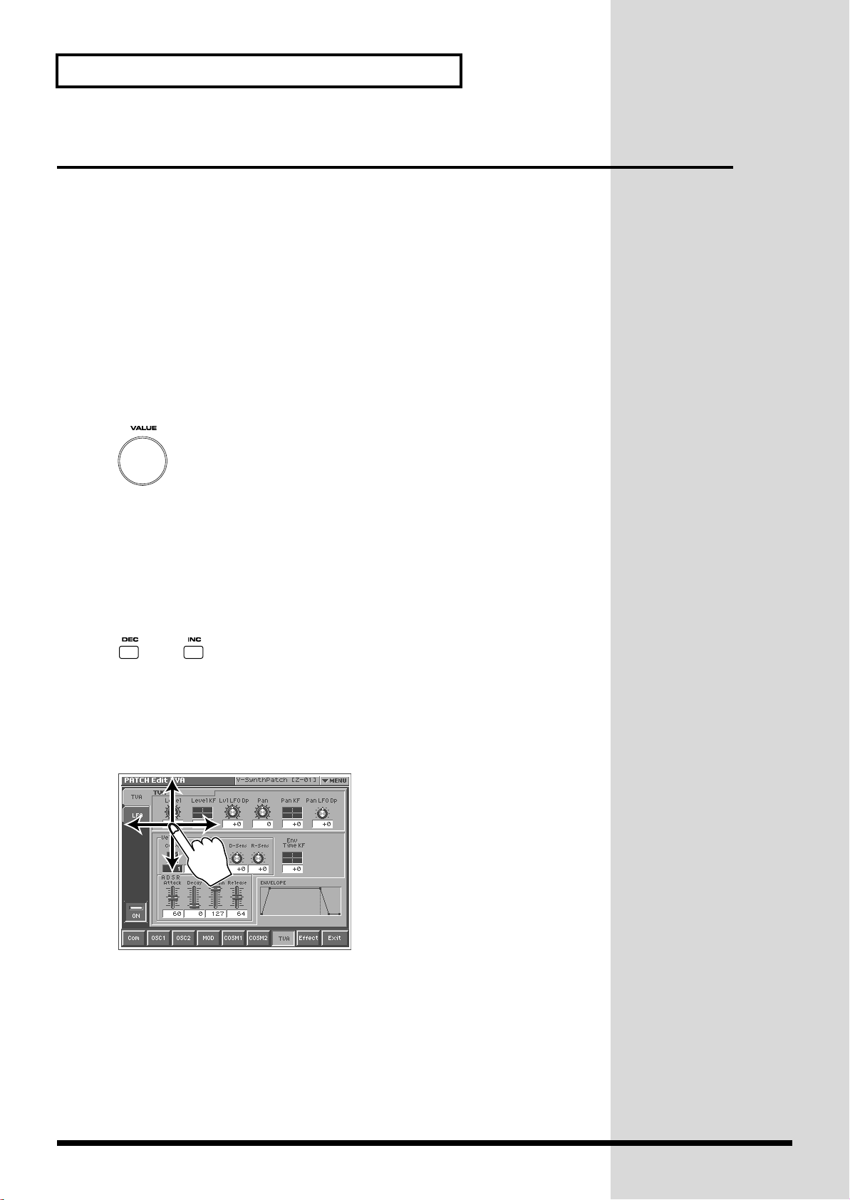
Basic Touch Screen Operation
Editing a Value
To edit a value, you can use the VALUE dial, [INC] [DEC], or drag on the touch
screen.
• In each V-Synth XT screen, you can select a value using the cursor as described
earlier, and modify its value.
• Each parameter has its own range of possible values. You cannot set any value
smaller than the minimum value or greater than the maximum value.
VALUE Dial
Turning the VALUE dial clockwise increases the value, and turning it
counterclockwise decreases its value. Hold down [SHIFT] as you move the VALUE
dial to increase value increments to make large value changes more quickly.
fig.01-10
[INC] and [DEC]
Press [INC] to increase the selected value, and [DEC] to decrease it. Keep the button
pressed for continuous adjustment. For faster value increases, keep [INC] pressed
down and press [DEC]. To decrease values quickly, keep [DEC] pressed down and
press [INC].
fig.01-11
Touch Screen
Touch a parameter value, and drag your finger up/down or left/right. Dragging
upward or to the right increases the value, and dragging downward or to the left
decreases the value.
fig.01-12
26
Page 28
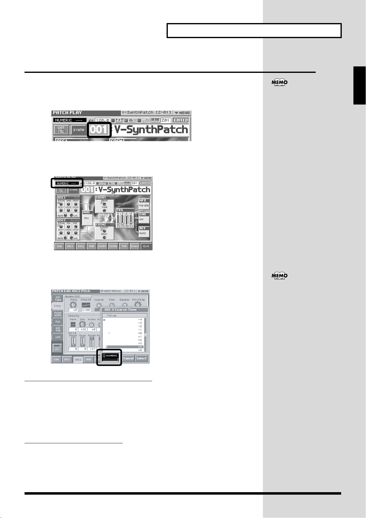
Basic Touch Screen Operation
Using the numeric keys for input
Using the numeric keys to switch patch numbers
When the cursor is located at a patch number, you can use the numeric keys to
switch patches.
Input a numeric value in the input value area.
• [0]-[9] buttons: Input the patch number.
• [BANK-], [BANK+] buttons: These function as ENTER.
Quick Start
The numeric keys also function
as the Patch Palette (p. 30).
Using the numeric keys to input parameters
When the cursor is located at an input location, pressing a numeric key will sometimes make a
list of parameter values appear.
When you can input a numeric value
Use the numeric keys to input a value in the input field.
• [0]-[9] buttons: Input numeric values.
• [BANK-] button: Reverse the sign of the input value.
• [BANK+] button: Clear the input value.
• [KEY PAD] button: Return the list to the middle.
You can also display the list by
pressing the VALUE dial
(ENTER) instead of the
numeric keys.
When you can input directly
The input area will blink “SELECT.”
• Press a button to input a value directly. From the top of the list, the items
correspond to the [0]-[9] buttons.
• The corresponding buttons will light. The current value will blink.
27
Page 29
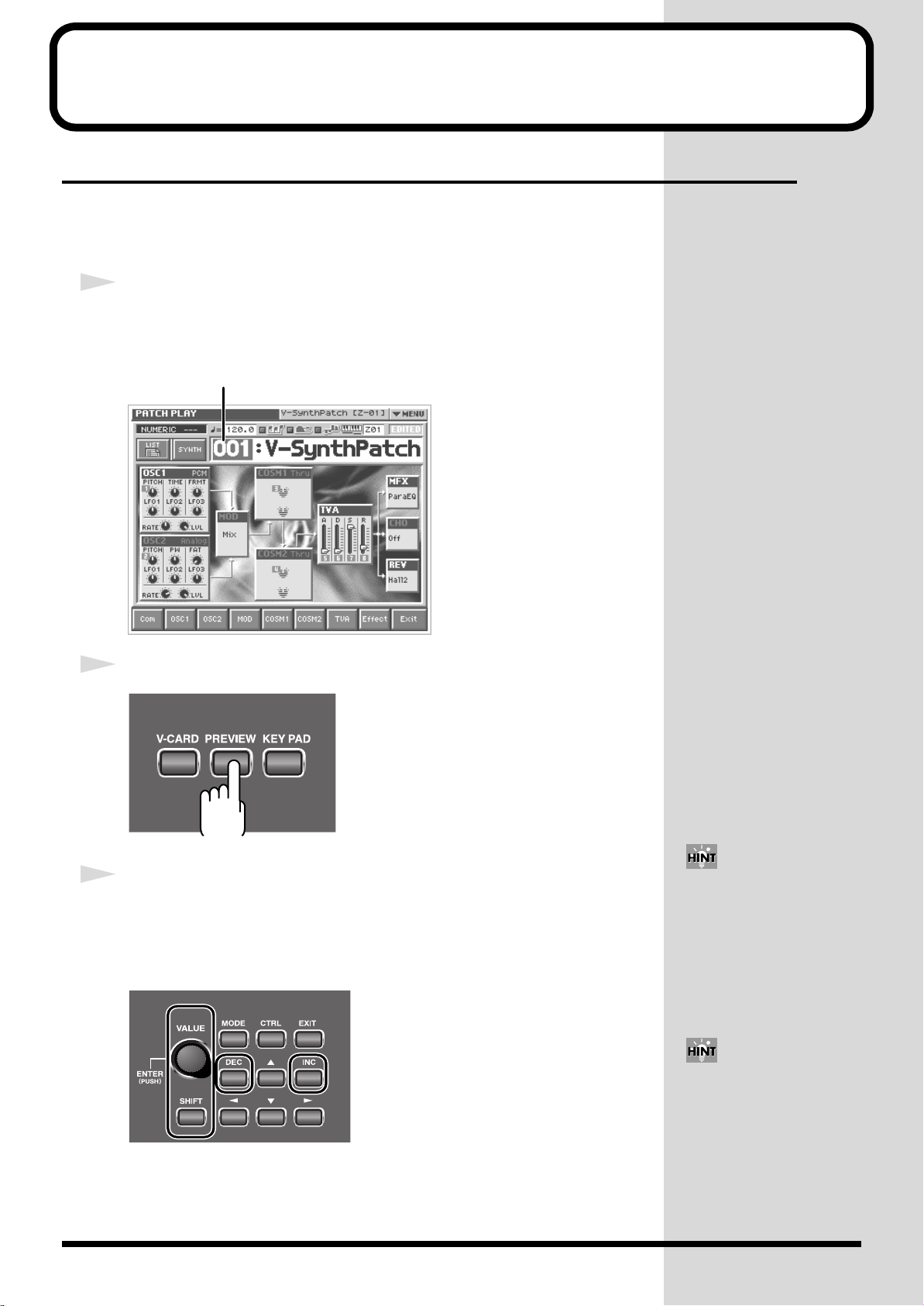
Try Out the Sounds
Selecting Patches and Playing Sounds
The V-Synth XT comes with a wide range of onboard sounds, including single tones
called patches. Let’s select a few patches to get an idea of the variety of sounds
available with the V-Synth XT.
1
Make sure the PATCH PLAY screen is displayed.
If the PATCH PLAY screen—shown below—is not displayed, press [EXIT] once or
twice until the PATCH PLAY screen appears.
fig.Q-06.e
Patch number
2
Press the [PREVIEW] button to audition the patch.
3
To change to a different patch, touch the patch number to highlight it,
and then turn the VALUE dial or press [INC] [DEC]. At this time you
can switch more rapidly by holding down [SHIFT] while you perform
these operations.
fig.Q-06a
You can also touch the patch
number display area and use
the numeric keys to switch
patches (p. 27).
Alternately, you can touch the
patch number and drag your
finger up and down—or right
and left—to change patches.
28
Page 30
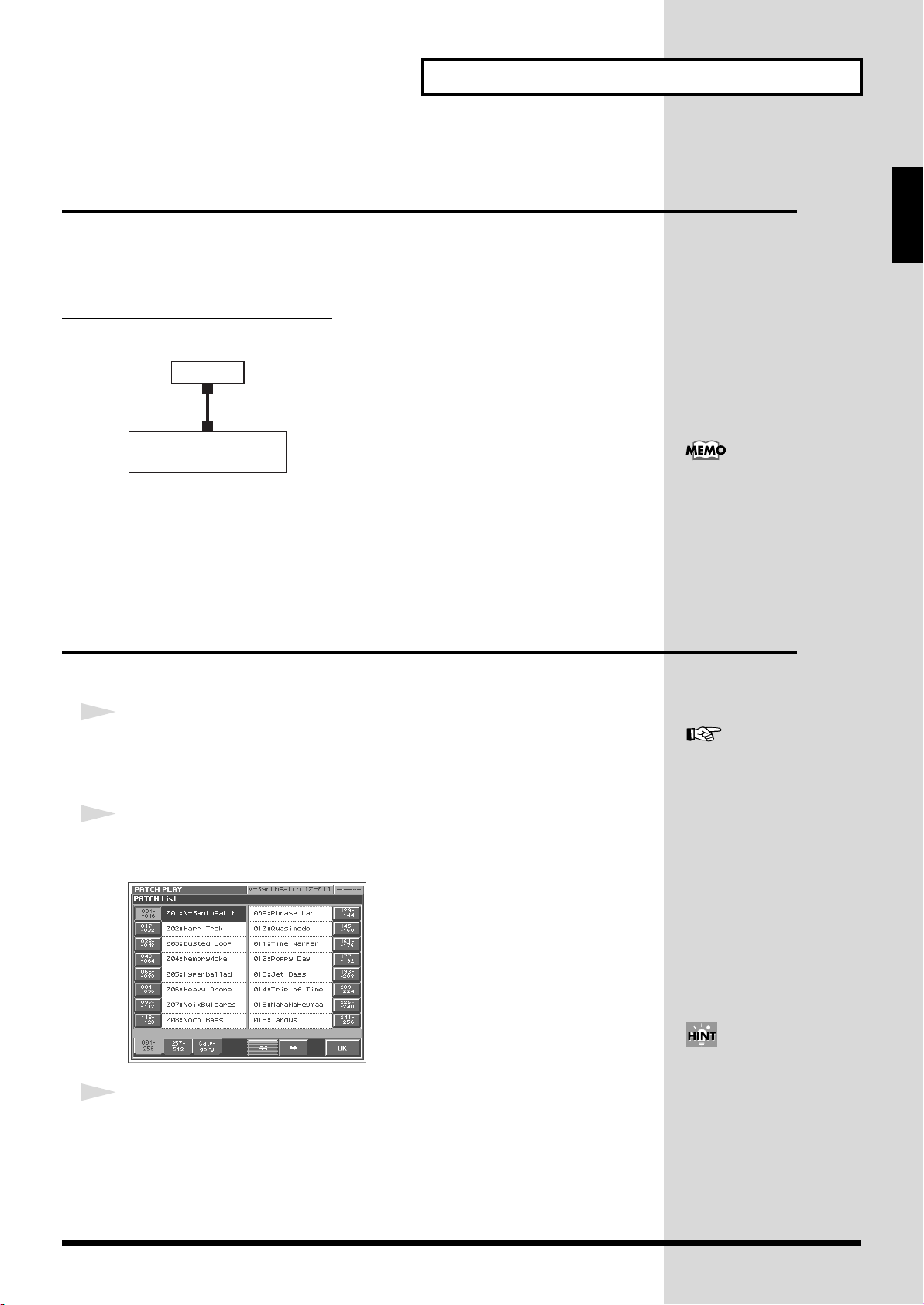
Try Out the Sounds
Playing a Patch on the V-Synth XT from an
External MIDI Device (MIDI Keyboard)
The V-Synth XT produces sound in response to MIDI messages it receives from an
external MIDI device such as a MIDI keyboard or sequencer.
Try connecting your MIDI keyboard and playing sounds on the V-Synth XT.
Connecting the MIDI Keyboard
Connect the MIDI keyboard as shown in the following.
fig.03-005.e
V-Synth XT
MIDI IN
MIDI OUT
MIDI keyboard
Matching MIDI Channels
In order for the V-Synth XT to respond to MIDI data sent by an external MIDI device,
both devices must be set to use the same MIDI channel or channels.
Quick Start
Executing a Factory Reset sets
the V-Synth XT’s reception
channel in Patch mode to “1.”
If you want to set this to a
channel other than 1, use “Part
MIDI ”(p. 126) to specify the
desired MIDI receive channel
for Part 1.
Selecting Patches from the List
You can easily find the desired patch by selecting it from the patch list.
1
Make sure the PATCH PLAY screen is displayed.
If the PATCH PLAY screen is not displayed, press [EXIT] once or twice until the
PATCH PLAY screen appears.
2
Touch <List> in the upper left area of the display.
The PATCH List window appears.
fig.Q-06b_60
3
Select a patch from the list.
Either turn the VALUE dial or use [INC] [DEC] to select a patch. You can also select
a patch by touching it on the display.
For details on the factory-set
patches in the V-Synth XT’s
memory, refer to “Sound List”
(separate booklet).
If you select a patch in the list
and play your external MIDI
keyboard, the selected patch
will sound. This is a useful
way to audition the sound of a
patch.
29
Page 31

Try Out the Sounds
The Patch Palette is available
only in the PATCH PLAY
screen.
4
To view other patches, touch <017-032>–<241-256>, located at either
side of the screen. To view higher-numbered patches, touch <257-
512>, located at the bottom of the screen.
5
Touch <OK>.
The patch is selected and the PATCH List window closes.
“
Selecting Patches by Category
”(p. 61)
Selecting Favorite Patches (Patch Palette)
If your favorite, frequently used patches are registered in the Patch Palette, you can
select them instantly by simply pressing Numeric Key [0]–[9].
In each patch palette you can register eight patches, corresponding to the [1]–[8]
keys. By using the [BANK] button to switch between the eight banks, you can
register a total of 64 patches.
1
Make sure the PATCH PLAY screen is displayed.
2
Press [KEY PAD]. The Patch Palette will appear in the screen.
3
Press Numeric Key [1]–[8] to select a patch.
You can also select patches by touching the
screen.
4
To switch between patch palette banks, press
[BANK-] / [BANK+].
5
To exit the Patch Palette, press [KEY PAD] once
again.
The [0] key and the [9] key
increment or decrement the
patch number in steps of 100.
For instructions on how to
register a favorite sound in the
patch palette, refer to
“Registering a Favorite
Patch (Patch Palette) ”(p. 76).
30
Page 32

Try Out the Sounds
Playing a drum set (Rhythm mode)
Rhythm mode lets you assign a different V-Synth sound to each note of the
keyboard. This lets you use the V-Synth XT as a rhythm sound module.
1
Press [MODE].
2
In the V-SYNTH XT MODE MENU window that appears, touch <RHYTHM>.
3
Use an external MIDI device to play the rhythm kit.
Quick Start
4
To switch rhythm kits, touch the area where the patch number is
displayed so it's highlighted, then turn the VALUE dial or use
[INC][DEC].
5
To exit RHYTHM mode, press [MODE], and then touch <PATCH> in the
V-SYNTH XT MODE MENU window that appears.
For details on how to edit
Rhythm mode settings, refer to
“Creating a Rhythm Kit
(Rhythm Mode) ”(p. 102).
31
Page 33

Try Out the Various Performance Features
What is the Time Trip
function?
One of the advantages of vari-
phrase is that the playback
location and speed of the wave
can be changed in real time.
The Time Trip function takes
advantage of this ability to
manually control the playback
location and speed of the
wave. In patches that use vari-
phrase, switch the Time Trip
Pad function to “TIME TRIP”
to use this function. While
playing your external MIDI
keyboard, touch the Time Trip
pad and the currently
sounding wave will stop at the
current playback location.
Then as you move your finger
from that point in a circle, the
wave playback will advance in
the direction of conventional
playback (clockwise), or the
reverse (counterclockwise).
Unlike “scratching” on a
turntable, this lets you control
the playback without affecting
the pitch, so you can play the
sound at the pitch you specify
from the keyboard.
The V-Synth XT is equipped with a variety of powerful performance features that
can raise your musical expressiveness to new levels. These include the Time Trip Pad
and the Arpeggiator. Take a moment to try out some of the V-Synth XT’s
performance features.
Manipulating Sounds with the Time Trip Pad
You can apply a variety of effects to the sound simply by touching your fingertip to
the Time Trip Pad.
1
Make sure the PATCH PLAY screen is displayed.
If the PATCH PLAY screen is not displayed, press [EXIT] once or twice until the
PATCH PLAY screen appears.
2
Press [CTRL] to access the Control screen.
fig.02-10
3
Choose the function that you want to control from the Time Trip pad,
and press the TIME TRIP PAD button for that function.
:
:
Apply the Time Trip effect.
Apply the effect that is specified by each patch.
The Time Trip pad will have
an effect if PCM is selected for
the oscillator (OSC1/OSC2)
and the “Time Trip Sw (Time
Trip Switch) ”(p. 87) is ON.
32
Page 34

Try Out the Various Performance Features
Time Trip Pad settings are
saved with each patch. This
means that you can create the
best Time Trip Pad settings for
each patch.
fig.02-11
fig.02-13
4
While you play your external MIDI keyboard to produce sound, place
your fingertip on the Time Trip pad and move your finger in the
following way.
If is on
The effect will be applied when you move your finger in a circle on the Time Trip
pad.
If is on
The effect will be applied when you move your finger up/down/left/right on the
Time Trip pad.
Quick Start
For details on using the Time
Trip Pad, refer to “
an Effect by Touching Your
Finger to the Pad (Time Trip
Pad)
”(p. 69).
Applying
33
Page 35

Try Out the Various Performance Features
Using Knobs to Modify the Sound in Realtime
(E1–E8 knobs)
By turning the E1–E8 knobs while you play, you can control the various functions
that’ve been assigned to them.
1
Make sure the PATCH PLAY screen (p. 60) is displayed.
If the PATCH PLAY screen is not displayed, press [EXIT] once or twice until the
PATCH PLAY screen appears.
2
While playing your external MIDI keyboard to produce sound, turn the
E1–E8 knobs
The sound will change according to the function assigned to each knob.
fig.Q-14
As shown in the following illustration, numbers (1–8) will appear in the PATCH
PLAY screen; these correspond to E1–E8.
In the PATCH PLAY screen, you can hold down the [SHIFT] key and use the cursor
up/down [ ][ ] buttons to switch the parameters that will be controlled.
In the menu that appears when you touch <▼ MENU> in the upper right of the
PATCH PLAY screen, you can touch “Global Knob” and use the buttons to switch
E1–E8 knob sets. These are saved as patch parameters.
34
If you want to edit the user knob settings, use the System settings “
128).
Preset settings
User settings
E1 - E8 Knob
”(p.
Page 36

Try Out the Various Performance Features
E1–E8 knobs in the editing screens
In the editing screens that appear when you touch the buttons at the bottom of the
PATCH PLAY screen (Com, OSC1, OSC2, etc.), the E1–E8 knobs function as follows.
In the menu that appears when you touch <▼MENU>, verify the “Indiv Knob”
setting.
If “Indiv Knob” is checked:
The knobs correspond to the knob numbers shown in each editing screen.
Quick Start
* You cannot change the knob number assignments of each editing screen.
If “Indiv Knob” is not checked:
The knob numbers are not shown in the editing screens. The knobs will correspond
to the knob numbers shown in the top screen (PATCH PLAY screen).
35
Page 37

Try Out the Various Performance Features
Playing Arpeggios (Arpeggiator)
The V-Synth XT provides an automatic arpeggio function (Arpeggiator). When you
turn on the arpeggiator and play your external MIDI keyboard, arpeggios are
produced automatically.
For example, if you press the keys of a C major chord, the V-Synth XT arpeggiates
the chord as C → E → G → C → E → G...
fig.Q-15
C4E4G4
E4 G4
C4
1
Make sure the PATCH PLAY screen is displayed.
If the PATCH PLAY screen is not displayed, press [EXIT] once or twice until the
PATCH PLAY screen appears.
2
Press Arpeggio <ON/OFF> to make the indicator light.
The arpeggiator is turned on.
fig.Q-17
3
Play your external MIDI keyboard.
The V-Synth XT arpeggiates what you’ve played.
C4
E4 G4
C4
E4
36
Page 38

Try Out the Various Performance Features
b
4
To adjust the tempo of the arpeggio, touch <TEMPO> in the location
shown below, and turn the [VALUE] dial.
Turning the dial toward the right makes the tempo faster, and turning it toward the
left makes the tempo slower.Hold down [SHIFT] as you move the VALUE dial to
increase value increments to make large value changes more quickly.
fig.Q-16a
5
To finish listening to the arpeggio, press Arpeggio <ON/OFF> again
so its indicator turns off.
Quick Start
Arpeggiator settings can be
saved with each patch. This
means that you can create the
est arpeggio settings for each
patch.
For details on using the
Arpeggiator, refer to “Playing
Arpeggios (Arpeggiator) ”(p.
64).
37
Page 39

Try Out the Various Performance Features
b
Using steps to vary the sound
(Multi Step Modulator)
The Multi Step Modulator is a function that modulates the value of various
parameters according to a sixteen-step sequence. On the V-Synth XT, the patterns of
this sequence are managed as “tracks.” You can simultaneously use up to four
tracks, with each track containing a different sequence. You can use the panel knobs
to freely modify the sequence pattern.
1
Make sure the PATCH PLAY screen is displayed.
If the PATCH PLAY screen is not displayed, press [EXIT] once or twice until the
PATCH PLAY screen appears.
2
At the bottom of the screen,
touch < Com >.
3
At the left side of the screen,
touch < Step Mod >.
The Multi Step Modulator screen appears.
4
At the top of the screen, turn < Step Switch > ON.
The Multi Step Modulator will be applied to the currently selected patch.
5
While you play the external MIDI keyboard to hear the sound, input
steps 1–16.
If you touch <▼ MENU > and select Hand Draw, you'll be able to draw the graph
directly with your finger.
You can also turn on the Multi
Step Modulator by using the
uttons of the PATCH PLAY
screen shown below.
For details on using the
Arpeggiator, refer to “Using
6
To exit the step sequencer, turn < Step Switch > OFF at the top of the
screen.
steps to vary the sound
(Multi Step Modulator) ”(p.
68).
38
Page 40

Try Out the Various Performance Features
Holding the notes you play (Key Hold)
The Key Hold function changes the way in which the patch will play when you press
a note on the MIDI keyboard. If Key Hold is on, the patch will start or stop sounding
each time you press a note. In other words, the patch will begin sounding when the
V-Synth XT receives a note-on, and will stop sounding when the next note-on is
received.
1
In the upper right of the screen, touch <▼ MENU>.
A pulldown menu appears.
fig.01-05_50
Quick Start
2
In the pulldown menu, touch < Key Hold >.
The Key Hold window will appear.
3
Turn < Hold Switch > ON.
4
Play the MIDI keyboard.
The patch will sound according to the key you pressed. When you press the same
key once again, the patch will stop sounding.
* If the Key Hold function is turned on, and you forget which key you pressed, the patch will
simply continue sounding. In such cases, press the key that is assigned as the “Panic Key” in
the Key Hold window. All notes that are being sounded by the Key Hold function will stop
sounding.
* If you change the Panic Key assignment, you must save the system settings as described in
“
Saving the System Settings (Write)
”(p. 122).
The Key Hold function is
turned “off” when you power
up the V-Synth XT.
39
Page 41

Creating a Patch
This chapter explains the steps for creating a patch on the V-Synth XT. Broadly
speaking, there are two ways to create a patch.
Using a template to create a patch intuitively
(the Sound Shaper function)
You can easily create a patch just by choosing a group and template.
Refer to “
Creating a patch from scratch
This section explains the basic procedure for creating a patch on the V-Synth XT.
Refer to “
Creating a patch intuitively (Sound Shaper)
The “Sound Shaper” function lets you create a patch simply by choosing a group and
template, and operating knobs and buttons to edit the relevant aspects of the sound,
just like a professional sound designer.
Creating a patch intuitively (Sound Shaper)
Initializing Patch Settings
”(p. 42).
”(p. 40).
1
Make sure that the PATCH PLAY screen is displayed.
2
At the upper right of the screen, touch <▼ MENU >.
A pulldown menu will appear.
3
In the pulldown menu, touch < Sound Shaper >.
The following window will appear.
40
Choose the “Group” and “Template” that are closest to the sound you want to create.
Use the list at the left to choose a group, and use the list at the right to choose a
template. Then touch < Enter >.
Page 42

Creating a Patch
4
A window like the following will appear.
While playing the external MIDI keyboard, use the eight switches and
knobs to adjust the sound.
• The [E1]–[E8] knobs correspond to the knobs in the screen.
• Some buttons have an on/off function, while others select choices from a list.
Quick Start
For each template, the most
suitable parameters have been
automatically selected for each
of the eight switches and
knobs.
5
At the bottom of the screen, touch the < FX > tab to make effect
settings.
From the top, the effects are MFX (multi-effect), chorus, and reverb.
• You can use the button for each effect to turn it on/off.
• If you want to switch the type of an effect, touch the effect name to highlight it,
and then turn the VALUE dial or use [INC][DEC].
• In the Sound Shaper you can edit only the main parameters of each effect, using
the on-screen knobs.
6
In the lower right of the screen, touch < Write > to open the “Patch
Write” screen, where you can save the patch you created.
To save your patch, use the procedure described in “
(PATCH Write)
”(p. 53).
Saving Patches
For details on each effect, refer
to “Effects List ”(p. 164).
For more about the Sound
Shaper function, refer to
“Creating a patch intuitively
(Sound Shaper) ”(p. 77).
41
Page 43

Creating a Patch
Initializing Patch Settings
This section explains the basic procedure for creating a patch on the V-Synth XT from
scratch.
First we will return the settings of the currently selected patch to a standard set of
values.
1
Make sure that the PATCH PLAY screen is displayed.
2
Touch <▼ MENU> in the upper right of the screen.
A pulldown menu appears.
fig.Q-24_60
3
Touch <PATCH Name> in the pulldown menu.
A window like the following appears.
fig.Q-25_60
4
Touch <EXECUTE>.
The initialization will be carried out, and you’ll be returned to the PATCH PLAY
screen.
42
Page 44

Creating a Patch
Selecting a Structure Type
The sounds of the V-Synth XT are produced by six elements (sections). Here’s how
to select the Structure Type, which determines how these elements are combined.
Section name Function
OSC1, OSC2
MOD This section mixes and modulates the two audio
COSM1, COSM2 This section applies a wide variety of processing
TVA This section creates time-variant changes in vol-
1
Make sure that the PATCH PLAY screen is displayed.
This section generates the sound on which a
patch is based. The sound is produced either by
built-in preset waves or sampled waves, or by
calculating an analog modeling waveform. An
external audio input source can also be used.
signals.
including filtering. This differs from the effects
in that effects are applied to the final mix of the
sound, COSM is applied to each individual note.
ume, and sets the pan position.
Quick Start
2
In the lower part of the screen, touch <COM>.
A screen like the following appears. If a different screen appears, touch the
<General> tab at the left side of the screen.
43
Page 45

Creating a Patch
3
Press Structure Type <TYPE 1>–<TYPE 3> to select a structure type.
Structure Type
Description
This is the most conventional structure on the VSynth XT. The sounds from OSC1 and OSC2 are
mixed by MOD, processed by COSM1 to shape
their tonal character (e.g., using SBF), and then
sent through COSM2 for additional tonal refinement (e.g., using TVF).
This structure connects OSC1 and OSC2 asymmetrically. This is effective when using a modulation that has the modulator set to anything
other than “MIX.” Typically, you will use OSC1
and COSM1 to create the basic sound, then select
the OSC2 sound and MOD settings to add variation, and finally select TVF in COSM2 to adjust
the tone.
In this structure, OSC1 is paired with COSM1,
and OSC2 is paired with COSM2. You can use a
controller such as the Time Trip Pad to morph
between the sound created by OSC1 and COSM1
and the sound created by OSC2 and COSM2.
44
Page 46

Creating a Patch
Switching Each Section On/Off
After deciding on the structure type to use, you can switch each section within that
structure on or off as desired.
1
Touch <Exit>. Make sure that the PATCH PLAY screen is displayed.
2
While holding down the [SHIFT] button on the front panel, touch the
relevant sections in the PATCH PLAY screen to turn individual
sections on or off as needed.
Section names shown in white characters are on, and those displayed in gray
characters are off.
fig.Q-26
On
Off
Quick Start
For example if “OSC1” and “OSC2” are both off, there will be no sound-producing
section, and no sound will be output.
45
Page 47

Creating a Patch
Setting Up the Oscillators (OSC1/2)
The oscillator sections produce the original sound, either by playing back an internal
PCM wave or a sampled wave, or by generating an analog modeling wave.
Selecting a Wave
1
Make sure that the PATCH PLAY screen is displayed.
2
In the lower part of the screen, touch <OSC1> (or <OSC2>).
A screen like the following appears. If a different screen appears, touch the <OSC
Type> tab at the left side of the screen.
fig.Q-28_60
fig.Q-29_60
Analog oscillator
PCM oscillator
46
3
Touch either <ANALOG> or <PCM> to select the type of oscillator.
4
In the Waveform area, select the wave you wish to use.
Make your selection while playing your external MIDI keyboard to hear the sounds.
For more about the oscillator
settings, refer to “Modifying
Waveforms (OSC1/OSC2)
”(p. 86).
Page 48

Creating a Patch
Mixing/Modulating Two Sounds (Mod)
The Modulator mixes and modulates the two audio signals.
Selecting a Modulator Type
1
In the lower part of the screen, touch <Mod>.
A screen like the following appears.
fig.Q-32_60
Quick Start
2
In the Modulator Type area, select the modulator type you wish to use.
Modulator Type
MIX
RING
FM
ENV RING
OSC SYNC
Description
Add OSC1 and OSC2.
Use OSC2 to apply ring modulation to OSC1.
Use OSC2 to apply FM (frequency modulation) to OSC1.
Use the envelope of OSC2 to control the volume of OSC1.
Synchronize the output waveform of OSC1 to the output
waveform of OSC2.
OSC SYNC is valid only when
OSC2 is an analog oscillator.
For more about the modulator
settings, refer to “Mixing/
Modulating Two Sounds
(MOD) ”(p. 93).
47
Page 49

Creating a Patch
For more about COSM
settings, refer to “
Applying
Various Effects to Each Note
You Play (COSM1/COSM2)
”(p. 93).
Applying COSM Modeling to Oscillators
(COSM1/2)
The COSM sections modify the sound in various ways, including filtering the sound.
COSM differs from the Effects section in that while Effects are applied to the final
mix of the sound, COSM is applied individually to each note.
Selecting a COSM Type
1
In the lower part of the screen, touch <COSM1> (or <COSM2>).
A screen like the following appears.
fig.Q-32a_60
2
Press the desired COSM type button to select the form of COSM.
Make your selection while playing your external MIDI keyboard to hear the sounds.
48
Page 50

Creating a Patch
Shaping a Sound’s Volume Over Time (TVA)
You can adjust the way in which the patch’s volume changes over time, or modify
the attack or decay of the sound.
1
In the lower part of the screen, touch <TVA>.
A screen like the following appears.
fig.Q-34_60
2
Use the “ENVELOPE” sliders in the lower left of the screen to adjust
the shape of each note’s volume.
“ENVELOPE” in the lower right of the screen shows a graphical representation of
the envelope produced by the current settings.
fig.Q-34a
Quick Start
Slider
For example, if you shorten a note’s attack time and lengthen its release time, the
note’s volume may be shaped like a note on a piano. If the sustain level is at
maximum, it may sound like an organ, and if the attack time is long, it may sound
like a string section.
Function
[A] Attack Time
Sets the time required for the volume of each note to reach its peak. This
time increases as you raise the slider.
Decay Time
[D]
Determines the time it takes for the note’s volume to drop from its peak
to its sustain level. If the sustain level is at its maximum, this has no effect.
[S]
Sustain Level
Determines the level at which the volume is maintained after the peak
has been reached. As long as you continue to press a key on the keyboard,
its note keeps sounding at this level.
[R]
Release Time
Sets the time it takes for a note’s volume to reach zero after you release
your finger from a key on a keyboard.
For details about volume
settings, refer to “Adjusting
the Volume and Pan (TVA)
”(p. 94).
49
Page 51

Creating a Patch
Adding the V-Synth XT Effects
Since the V-Synth XT effects have such a profound impact on its sounds, turn them
on to listen to the sound itself so you can better evaluate the changes you’re making.
Actually, sometimes just changing effects settings can give you the sound you want.
Three separate effects are always available in the V-Synth XT. You can
independently edit each effect’s settings.
MFX
(Multi-Effects)
Chorus
Reverb
The V-Synth XT contains 41 different multi-effects, including distortion and a rotary-speaker simulation.
Chorus adds a sense of depth and spaciousness to
patches.
Reverb adds ambience that emulates the sound of various physical spaces, such as concert halls or auditoriums.
For details about effect
settings, refer to “Setting
Effects for a Patch (Effect)
”(p. 97).
50
Page 52

Creating a Patch
Saving Patches You’ve Created
When you edit the settings of a patch, the PATCH PLAY screen displays <EDITED>
to remind you that the patch’s settings have been modified. If <EDITED> is
displayed, you will lose your edited patch settings if you switch to another patch or
turn off the power. If you want to keep a patch whose settings you have edited,
assign a name to the patch and then perform the
fig.Q-36
Naming Patches (PATCH Name)
Before you save your patch, give it a new name as follows.
Save
Quick Start
operation.
1
Make sure that the patch you want to name is selected.
2
Touch <▼ MENU> in the upper right of the screen.
A pulldown menu appears.
fig.Q-37_60
51
Page 53

Creating a Patch
3
Touch <PATCH Name> in the pulldown menu.
The PATCH Name window appears.
fig.Q-38_60
4
Enter a name into the text box by touching the desired characters. For
this example, let’s enter “My Patch1” as the currently selected patch’s
name.
4-1.
Touch <Clear> to erase all characters from the text box.
4-2.
Touch <Shift> to turn it on, and then touch <M> to enter a capital
“M.”
4-3.
Touch <Shift> to turn it off, and then touch <y> to enter a lower-
case “y.”
4-4.
Touch <→> to move the cursor one character to the right.
4-5.
Touch <Shift> to turn it on, and then touch <P> to enter “P.”
4-6.
Touch <Shift> to turn it off, and then successively touch
<a><t><c><h><1>.
5
When you’ve finished entering the name, touch <OK> to close the
PATCH Name window.
52
Page 54

Creating a Patch
Saving Patches (PATCH Write)
After you've named your patch, save it as follows.
1
Make sure that the patch you want to save is selected.
2
Touch <▼ MENU> in the upper left area of the display.
A pulldown menu appears.
fig.Q-38a_60
3
Touch <PATCH Write> in the pulldown menu.
The PATCH Write window appears.
fig.Q-39_60
Quick Start
4
Choose the save destination (Destination). Turn the VALUE dial to
select an unused patch number.
* The patch you select (as the save destination) will be erased when it is overwritten by the
newly saved patch.
• To move through the patches more quickly, you can hold down [SHIFT] and turn
the VALUE dial.
• If you touch < Compare > you'll be able to play the external MIDI keyboard to
audition the patch that is at the save destination you choose (the Compare
function).
• If you touch < List >, the PATCH List window will open, allowing you to choose
a save-destination patch from a list.
5
Touch <Execute>.
When shipped from the
factory, the V-Synth XT
already contains a collection of
patches. When you save your
own patches, you replace the
factory patches. If you wish to
restore the original patches,
use the Factory Reset operation
(p. 147).
53
Page 55

Creating a Patch
Turning Off the Power
1
Before you turn off the power, consider these two questions:
• Have the volume controls for the V-Synth XT and all connected audio devices
been turned to their lowest settings?
• Have you saved your V-Synth XT sounds or other data you’ve created? (p. 53)
2
Turn off the power for all connected audio devices.
3
Turn off the POWER switch located on the front panel of the V-Synth
XT.
fig.Q-02.e
ON OFF
945
* If you need to turn off the power completely, first turn off the POWER switch, then unplug
the power cord from the power outlet. Refer to
Power Supply
(p. 4).
54
Page 56

Reference
55
Page 57

Overview of the V-Synth XT
Zone 16
Zone 15
Zone 2
Zone 1
Patch
How the V-Synth XT Is Organized
Basic Structure
Sound Generator Section
The sounds you play on the V-Synth XT are called
patch consists of a
zones
(which allow for sixteen individual setups for sixteen key
ranges), and three
fig.01-02.e
structure
effects
(an arrangement of its six sections),
.
patches
. Each
Effects
MFX
CHORUS Applies a chorus effect to give the sound
REVERB Applies a reverb effect to add ambience to
function
The multi-effects are multi-purpose effects
that can completely change the nature of
the patch’s sound. There are 41 different effects types; select and use the type that suits
your aims.
depth and spaciousness.
the sound.
Polyphony
The maximum polyphony of the V-Synth XT depends on the OSC
and COSM types used by the patch.
Changing the effect type or switching effects on/off does not
affect the available polyphony.
About Multitimbral Performance
The V-Synth XT allows up to 16-part multitimbral operation, and can
be played multitimbrally by performance data sent from an external
device. You can use the V-Synth XT to play the sounds of a song you
created on your sequencer, or as part of an ensemble. From the MIDI
keyboard you can play only the patch that is assigned to part 1. The
PATCH Information window shows you the patch that is assigned
to each part (p. 147).
A sound module that allows you to control multiple sounds
independently in this way is called a
multitimbral sound module
.
Section name
OSC1, OSC2
MOD This section mixes and modulates the two
COSM1, COSM2 This section applies a wide variety of pro-
TVA This section creates time-variant changes in
Function
This section generates the sound on which
a patch is based. The sound is produced either by built-in preset waves or sampled
waves, or by calculating an analog modeling waveform. An external audio input
source can also be used.
audio signals.
cessing including filtering. This differs
from the effects in that effects are applied to
the final mix of the sound, COSM is applied
to each individual note.
volume, and sets the pan position.
56
Page 58

Overview of the V-Synth XT
V-Synth XT
Internal Memory
Project
Wave
999
Patch
512
System
Preset Memory
Memory card
Project
Patch
512
Wave
999
System
Save
Load
USB
Computer
SaveSelect
Work Area Temporary Area
Memory
Memory Structure
fig.01-03.e
Project
The largest unit of memory used by the V-Synth XT is the
project contains up to 512 patches, up to 999 waves, and various
system settings.
The V-Synth XT uses one project at a time.
Internal Memory
The V-Synth XT has
V-Synth XT is shipped from the factory, this memory already
contains patch and wave data, but you are free to overwrite any of
this. You can always restore the memory to the factory-set contents
(Factory Reset).
internal memory
project
. A
that stores a project. When the
Work Area/Temporary Area
When you turn on the power of the V-Synth XT, or when you load a
project in Disk mode, the project data is placed in temporary
memory called the
Sampling and sample editing operations modify the data that is in
the work area.
The currently playable patch data is then further placed (from the
work area) into a location called the
that even after editing a patch, you can return to the unedited
condition by once again recalling that patch.
Since sample data and patch data that you edit will disappear if you
simply turn off the power, you must
want to keep your changes.
work area
.
temporary area
save
. This means
(SAVE/WRITE) it if you
Memory cards
Internal memory can hold only one project, but you can use
commercially available memory cards to store additional projects.
Sampling Memory
The amount of memory you can use for sampling will depend on the
state of the project that is currently loaded into the work area. With
the factory-set project, there is approximately 115 seconds (stereo) /
230 seconds (monaural) of sampling memory. If you delete the
factory-set waves, you will be able to use a maximum of
approximately 280 seconds (stereo) / 560 seconds (monaural) of
sampling memory. However since a maximum of approximately 56
seconds (stereo) / 113 seconds (monaural) can be saved in internal
memory, you will need to use a commercially available memory
card if you want to store more samples than this.
* The above values are for when the sample is encoded using the “LITE”
type (p. 119).
The factory-set waves can be restored using the Factory Reset
operation (p. 147) even if they have been erased.
Preset Memory
Preset memory contains the state of the internal memory when the
unit is shipped from the factory. If, after erasing the internal
memory, you once again want to use the factory-set patches or
waves, you can either perform the Factory Reset operation or use
Disk mode to import the factory data from preset memory.
USB
If you connect the V-Synth XT to your computer via a USB cable,
projects, patches, and wave data in the V-Synth XT’s internal
memory or on a memory card can be saved (backed up) to the hard
disk or other media on your computer.
In addition, wave data created on the V-Synth XT can also be used
by software running on your computer, or wave data created by
your computer software can be used on the V-Synth XT.
Overview
57
Page 59

Overview of the V-Synth XT
Basic Operation of the V-Synth XT
Changing Operating Modes ([MODE])
The V-Synth XT has nine operating modes: Patch mode, Rhythm
mode, Sample mode, System mode, Disk mode, USB mode,
Calibration mode, Factory reset mode and Demo mode. To access
the desired V-Synth XT feature, you must select the appropriate
mode.
Here’s how to change modes.
1.
Press [MODE].
The V-SYNTH XT MODE MENU window appears.
fig.MODE_50
Patch Mode (p. 60, p. 72)
fig.PATCH_50
In this mode you can play a single patch from the keyboard, and
edit patch settings.
Rhythm Mode (p. 102)
fig.PATCH_50
2.
Touch the touch screen to select the desired mode.
When you select a mode, the screen for that mode appears. The
currently selected mode is shown in the upper left of each
screen.
fig.01-04
In this mode you can play a rhythm kit from the keyboard, and
edit rhythm kit settings.
Sample Mode (p. 104)
fig.SAMPLE_50
In this mode, you can sample the waves that form the basis of
the sounds you create, and edit the sampled waves.
58
Page 60

Overview of the V-Synth XT
Disk Mode (p. 131)
fig.DISK_50
In this mode, you can perform operations related to disks, such
as saving data on a disk or loading data from a disk.
USB Mode (p. 138)
fig.USB_50
Factory Reset Mode (p. 147)
fig.FACTORY_50
Overview
In this mode, you can reset to default factory settings.
Demo Mode
This is a demo screen mode that introduces you to the V-Synth
XT's functionality.
System Mode (p. 122)
fig.SYSTEM_50
In this mode, you can connect the V-Synth XT to your computer
and exchange patch or wave data.
Calibration Mode (p. 148)
fig.CALIBRATION_50
In this mode you can adjust the response of the touch screen.
In this mode, you can set the overall behavior of the V-Synth XT,
such as its tuning and how it handles received MIDI messages.
59
Page 61

Playing in Patch Mode
Patch mode is the mode in which you can play the keyboard using a
single sound (patch or rhythm set).
About the PATCH PLAY Screen
Displaying PATCH PLAY Screen
To access the PATCH PLAY screen, use the following procedure.
1.
Press [MODE].
The V-SYNTH XT MODE MENU window appears.
fig.MODE_50
Functions in the PATCH PLAY Screen
fig.02-01.e
Indicates a list of patches.
Indicates the current mode.
Indicates the patch number (numeric key).
Indicates/sets the tempo.
Arpeggio, Arpeggio Hold, Multi Step Modulator
Indicates the name and zone
of the selected patch.
Indicates/sets the zone
Opens the pulldown menu.
Indicates/selects the
number and name
of the selected patch.
Graphically displays
the parameter settings
of the selected patch.
Displays the various patch setting screens.
Return to the PATCH PLAY screen.
2.
Touch <PATCH>.
You will enter Patch mode, and the PATCH PLAY screen
appears.
fig.PATCH_50
Selecting a Patch
V-Synth XT contains 512 patches for you to select and use.
All of these patches can be overwritten.
1.
Access the PATCH PLAY screen (p. 60).
fig.02-02.e
Patch number
2.
Move the cursor to the patch number, either by using the
cursor buttons or by touching the patch number display.
3.
Turn the VALUE dial, or press [INC][DEC] to select a patch
number. You can also do this by dragging on the touch
screen.
60
You can also touch the patch number display area and use the
numeric keys to switch patches (p. 27).
Page 62

Playing in Patch Mode
Page navigation button
Selecting Favorite Patches (Patch Palette)
You can bring together your favorite and most frequently used
patches in one place by registering them into the patch palette. By
using this function, you can rapidly select favorite patches from
internal memory or a Wave Expansion Board.
In each patch palette you can register eight patches, corresponding
to the [1]–[8] keys. By using the [BANK] button to switch between
the eight banks, you can register a total of 64 patches.
For details on how to register a patch in the patch palette, refer
to
“Registering a Favorite Patch (Patch Palette)”
1.
Access the PATCH PLAY screen (p. 60).
* The Patch Palette is available only in the PATCH PLAY screen.
2.
Press [KEY PAD]. The Patch Palette will appear in the
screen.
(p. 76).
Selecting Patches by Category
The V-Synth XT provides a Patch Search function which allows you
to specify a type (category) of patch so that you can quickly find the
desired patch. There are a total of 16 categories.
1.
Access the PATCH PLAY screen.
2.
Touch the category button in the upper left area of the
display.
The PATCH List window appears, and the categories will be
displayed at both sides of the screen.
fig.01
fig.02e
Playing in Patch Mode
3.
Press Numeric Key [1]–[8] to
select a patch.
You can also select patches by
touching the screen.
The [0] key and the [9] key increment
or decrement the patch number in
steps of 100.
4.
To switch between patch palette
banks, press [BANK-] / [BANK+].
5.
To exit the Patch Palette, press [KEY PAD] once again.
61
Page 63

Playing in Patch Mode
3.
Touch the desired category, and select a patch from the list.
You can move to a different page within the same category by
touching a page navigation button in the bottom of the screen.
Category
SYNTH
LEAD Lead Lead
PAD/STING Pad/Strings Pad/Strings
VOX/CHOIR Vox/Choir Voice/Choir
PIANO/KBD Piano/Keyboards Piano/Keyboards
BASS/GUITAR Bass/Guitar Bass/Guitar
WINDS Winds Winds
BELL/
MALLET
MELO SEQ Melodic Sequence Melodic (i.e., pitched)
RHY SEQ Rhythmic Sequence Rhythmic (i.e., non-
ARPEG Arpeggio Arpeggio
FX/AMBI FX/Noise/
ETHNIC Ethnic Ethnic
DRUM/PERC Drum/Percussion Drum/Percussion
COMBI/
OTHERS
NO ASSIGN No Assign No Assign
“Assigning the Category of a Patch”
Synth Synth
Bell/Mallet/Hit Bell/Mallet/Hit
Ambient
Combination/
Others
Contents
sequences
pitched) sequences
Effect/Noise/
Ambient
Combinations using
zones/other
(p. 74)
Selecting Patches from the List
You can display a list of patches and select a patch from that list.
1.
Access the PATCH PLAY screen (p. 60).
2.
Touch <List> in the upper left area of the display.
The PATCH List window appears.
fig.02-04_50
3.
Select a patch from the list.
Either turn the VALUE dial or use [INC][DEC] to select a patch.
You can also select a patch by touching it on the display.
If you select a patch in the list and play the external MIDI
keyboard, the selected patch will sound. This is a useful way to
audition the sound of a patch.
4.
To view other patches, touch <017-032>–<241-256>, located
at either side of the screen. To view higher-numbered
patches, touch <257-512>, located at the bottom of the
screen.
5.
Touch <OK>.
The patch is selected and the PATCH List window closes.
62
Page 64

Playing in Patch Mode
Playing Single Notes (Mono)
When using a patch for a naturally monophonic instrument such as
sax or flute, it is effective to play in mono.
1.
Access the PATCH PLAY screen (p. 60).
2.
At the bottom of the screen, touch <Com>.
3.
In the left side of the screen, touch the <General> tab.
The Patch Edit Com General screen appears.
fig.02-07_50
4.
In the “Mono/Poly” field, touch < >.
Now you can play in mono mode.
Making Controller-related Settings
(Control)
On the panel, press [CTRL] to access the Control screen.
The Control screen provides the following functions.
< External Control >
If this button is on, the E1–E8 knobs will control an external MIDI
device. The MIDI controller number that is transmitted when you
turn the E1–E8 knobs is specified by
External CC)”
(p. 129).
“E1 - E8 ExtCC (E1–E8
Playing in Patch Mode
Creating Smooth Pitch Changes (Portamento)
Portamento is an effect which smoothly changes the pitch from the
first-played key to the next-played key. By applying portamento
when Mono mode is selected (see the preceding item), you can
simulate performance effects such as slurring on a violin.
1.
Access the PATCH Edit Com General screen (p. 63).
fig.02-07_50
2.
In the “Portamento” field, touch the on/off switch to turn it
“ON.”
You’re ready to play portamento.
3.
When you want to change the portamento setting, edit the
following parameters in the screen of step 2.
Mode
(Portamento Mode),
(Portamento Time),
Sens)
Type
(Portamento Type),
Time Velo Sens
Time
(Portamento Time Velocity
< V-LINK >
If you turn this button on, the V-Synth XT will be in V-LINK mode,
where it can control video equipment (p. 71).
< Time Trip Pad >
This lets you use the “Time Trip Pad” function (p. 69) which allows
you to apply various effects to the sound by moving your finger over
the pad displayed in the screen.
< Arpeggio >
This switches the Arpeggio function (p. 64) on/off.
See p. 79 for each parameter’s functions.
63
Page 65

Playing in Patch Mode
Playing Arpeggios (Arpeggiator)
The V-Synth XT comes with an
automatically. Once you turn on the arpeggiator, the keys you press
will automatically be played as an arpeggio.
1.
Access the PATCH PLAY screen (p. 60).
2.
Press Arpeggio <ON/OFF> to make the indicator light.
The arpeggiator is turned on.
fig.Q-17
3.
Play your external MIDI keyboard.
The V-Synth XT arpeggiates what you’ve played.
4.
To adjust the tempo of the arpeggio, touch <TEMPO> in the
location shown below, and turn the [VALUE] dial.
Turning the dial toward the right makes the tempo faster, and
turning it toward the left makes the tempo slower.Hold down
[SHIFT] as you move the VALUE dial to increase value
increments to make large value changes more quickly.
arpeggiator
that can play arpeggios
Holding an Arpeggio
By using the following procedure, you can produce arpeggios even
without continuing to press the keyboard.
1.
Press Arpeggio <ON/OFF> to turn the Arpeggiator on.
2.
Press Arpeggio <HOLD> to make the indicator light.
3.
Play the MIDI keyboard.
4.
If you play a different chord or notes while the arpeggio is
being held, the arpeggio will change accordingly.
5.
To cancel Arpeggio Hold, press Arpeggio <HOLD> again.
5.
To finish listening to the Arpeggio, press Arpeggio <ON/
OFF> again so its indicator turns off.
When Using a Hold Pedal
If you play an arpeggio while pressing the hold pedal, the arpeggio
will continue to be played even if you release the keyboard.
1.
Connect a pedal switch (DP series) to the HOLD PEDAL jack
of your external MIDI keyboard.
2.
Press Arpeggio <ON/OFF> to turn the Arpeggiator on.
3.
Play the keyboard while pressing the hold pedal.
4.
To play another chord, release the pedal, press it again as
you play the next chord.
64
Page 66

Playing in Patch Mode
Cursor
Pattern input area
Making Arpeggiator Settings
1.
Access the PATCH PLAY screen (p. 60).
2.
At the bottom of the screen, touch <Com>.
3.
In the left side of the screen, touch the <Arpeggio> tab.
The PATCH Edit Com Arpeggio screen appears.
fig.02-09_50
In this screen you can set the following arpeggiator parameters.
Arpeggio Switch:
Hold:
Switch between Hold On/Hold Off for the Arpeggiator
performance.
Patch Tempo:
Octave Range:
in octave units.
KBD Velo:
Duration:
modify the rhythmic feel (groove) of the performance.
Motif:
Specifies how the arpeggio will be sounded.
Shuffle Rate:
which notes are sounded.
Shuffle Resolution:
note value.
For details regarding each parameter, refer to
82).
Switches the Arpeggiator on/off.
Specify the tempo of an arpeggio.
Specify the range of the arpeggio performance,
Specify the note strength of the keys you play.
Vary the strength and note length of the accents to
Create shuffle rhythms by modifying the timing at
Specify the timing of the notes in terms of
“Arpeggio”
(p.
Creating an Original Arpeggio Pattern
(Pattern Edit)
You can create your own
arpeggio will be sounded. This gives you even more interesting
ways to use arpeggios.
An arpeggio pattern is a set of data that can be up to 32 steps
(horizontally) x 16 lines (vertically).
An arpeggio pattern can be saved for an individual patch as part
of the patch settings. This means that you can create a patch
designed specifically for that arpeggio pattern.
About the Pattern Edit Window
1.
Access the PATCH Edit Com Arpeggio screen (p. 65).
2.
Touch <Pattern Edit>.
The Pattern Edit window will appear.
fig.02-09a.e
State
Specifies the status of each line.
NOTE:
Note pitch
CTRL:
Control change
arpeggio pattern
that specifies how an
Playing in Patch Mode
Arpeggiator settings can be saved with each patch as part of the
patch settings. This means that you can create patches that
contain the most effective settings.
Note/CC (Note/Control Change)
Specifies the note number or control change number assigned to
each line. If Status is “NOTE,” this will be a note number (C-1–G9). If
Status is “CTRL,” this will be a control change number (0–127).
Pattern Input Area
This area is where you input or edit notes or control changes. The
symbols have the following meaning:
●
: Note
=: Tie
❍
: Control change
Value
Shows the velocity of the note or the value of the control change
selected in the pattern input area.
65
Page 67

Playing in Patch Mode
0, 32, 64, 96, 127, Tie/Clr
When inputting notes:
with the velocity shown on that button will be input at the cursor
location within the pattern input area. When you touch <Tie>, a tie
will be input at the cursor location.
When inputting control changes:
shown on that button will be input at the cursor location within the
pattern input area. When you touch <Clr>, the selected control
change will be erased.
When you are editing, these buttons modify the velocity of the note
that is selected in the pattern input area, or the value of the control
change.
You can also input the note velocity or control change value by
using the VALUE dial or [INC][DEC].
When you touch one of these buttons, a note
A control change with the value
Grid
Specifies the note value that will correspond to “one step” of the
arpeggio pattern.
fig.02-09b.e
(Dotted eighth note),(Eighth note),(Quarter note),
(Sixteenth note), (Dotted sixteenth note),
(Thirty-second note)
End Point
Specifies the pattern length as a number of steps (1–32).
Clear
Erases the pattern data (p. 67).
Creating a Pattern by Playing in Real Time
(Real Rec)
This method lets you create a pattern in a way similar to realtime
recording on a sequencer. Your playing on the MIDI keyboard and
your controller operations will be recorded “as is.”
1.
Specify the Grid and End Point of the arpeggio pattern that
you will be creating.
Move the cursor to each value box and set the value.
2.
Touch <Real Rec>.
The V-Synth XT will be in realtime-input standby mode, and the
metronome will sound a guide rhythm.
fig.02-09c_50
3.
In time with the guide rhythm sounded by the metronome,
play the MIDI keyboard and operate the controllers.
You can repeatedly record over the pattern length (number of
steps) you specified in step 1. On each pass, you can add new
notes and control changes to build up the pattern.
Real Rec (Realtime Recording)
Use realtime recording to create a pattern (p. 66).
Step Rec (Step Recording)
Use step recording to create a pattern (p. 67).
The notes (specified pitches) and control changes in a single
pattern cannot exceed a total of 16. All further (seventeenth and
later) notes having a new pitch or control changes will not be
recorded.
4.
When you are finished with realtime input, touch <Stop>.
The metronome guide will stop sounding.
66
Page 68

Playing in Patch Mode
Creating a Pattern by Inputting One
Step at a Time (Step Rec)
This method lets you create a pattern in a way similar to step-
recording on a sequencer. You can record notes and control changes
by inputting them one by one.
1.
Specify the End Point of the arpeggio pattern that you want
to create.
Move the cursor to the End Point value box and make the
setting.
2.
Touch <Step Rec>.
The V-Synth XT will be in step-input standby mode.
fig.02-09d_50
3.
Play the MIDI keyboard or operate a controller to input the
first step.
You can repeatedly record over the pattern length (number of
steps) you specified in step 1. On each pass, you can add new
notes and control changes to build up the pattern.
Erasing a Pattern (Clear)
Here’s how to erase data from the pattern. You can erase a specific
line or the entire pattern.
1.
To specify a line that you want to erase, move the cursor to
that line.
2.
Touch <Clear>.
A window like the following will appear.
fig.02-09e_50
3.
To erase a line of data, touch <LINE CLEAR>. To erase the
entire pattern, touch <ALL CLEAR>. If you decide you don’t
want to clear anything, touch <CANCEL>.
Playing in Patch Mode
• To input a tie, hold down the key of the note that you want to tie
and press [ ]. You will advance as many steps as the number
of times you press [ ].
• Step input records the strength (velocity) with which you press
the key, and this will be reflected in the level or dynamics of the
arpeggiated notes.
• Control changes will be input with the value that was in effect
when you pressed [ ].
• The notes (specified pitches) and control changes in a single
pattern cannot exceed a total maximum of 16. A newly pitched
note or a control change that would exceed this total will not be
recorded.
• Be aware that if you input another note while still holding down
the key for the previously input note, these notes will be input as
a chord located at the same step.
4.
When you are finished with step input, touch <Stop>.
67
Page 69

Playing in Patch Mode
Using steps to vary the sound (Multi Step Modulator)
The Multi Step Modulator is a function that modulates the value of
various parameters according to a sixteen-step sequence. On the V-
Synth XT, the patterns of this sequence are managed as “tracks.” You
can simultaneously use up to four tracks, with each track containing
a different sequence. You can use the panel knobs to freely modify
the sequence pattern.
1.
Access the PATCH PLAY screen (p. 60).
2.
At the bottom of the screen, touch <Com>.
3.
In the left side of the screen, touch <Step Mod>.
The Multi Step Modulator screen appears.
6.
Make settings for the track.
Touch one of the tabs for a track name you turned ON in step 5.
7.
While playing the external MIDI keyboard to hear the sound,
input steps 1–16.
The V-Synth XT's E1–E8 knobs correspond to knobs 1–8 and 9–
16. To switch between 1–8 and 9–16, hold down the [SHIFT] key
and use the cursor up/down [ ][ ] buttons (the frame in the
screen will move).
4.
At the top of the screen, turn < Step Switch > ON.
The Multi Step Modulator will be applied to the currently
selected patch.
You can also turn on the Multi Step Modulator by using the
buttons of the PATCH PLAY screen shown below.
5.
Press < A >–< D > to turn tracks on/off as desired.
* If you turn all of the tracks off, there will be no effect even if < Step
Switch > is ON.
If you touch <▼ MENU > and select Hand Draw, you'll be able
to draw the graph directly with your finger.
If you touch < SMOOTH >, the graph will be smoothed. This
will make the change in the sound occur gradually, producing a
more LFO-like result.
The step bar shown at the far right (number 17) is the same as
the one that appears at the far left (number 1). This is helpful
when you're setting up a looping sequence.
The parameter that is modulated by each track will depend on
the patch. In the screen, you can touch Destination < List > to
change the assigned parameter.
8.
In the same way, make settings for other tracks you turned
on in step 5.
9.
If you want to stop using the step sequence, turn <
StepSwitch > OFF in the screen.
68
For details regarding each parameter, refer to
Modulator”
(p. 83).
“Multi Step
Page 70

Playing in Patch Mode
What is the Time Trip function?
One of the advantages of VariPhrase is that the playback
location and speed of the wave can be changed in real time. The
Time Trip function takes advantage of this ability to manually
control the playback location and speed of the wave. In patches
that use VariPhrase, switch the Time Trip Pad function to
“TIME TRIP” to use this function. While playing the keyboard,
touch the Time Trip pad and the currently sounding wave will
stop at the current playback location. Then as you move your
finger from that point in a circle, the wave playback will
advance in the direction of conventional playback (clockwise),
or the reverse (counterclockwise). Unlike “scratching” on a
turntable, this lets you control the playback without affecting
the pitch, so you can play the sound at the pitch you specify
from the keyboard.
Applying Various Effects to the Sound
The V-Synth XT provides numerous ways in which you can make
your performance more expressive, such as the Time Trip pad and
E1 – E8 knobs.
Applying an Effect by Touching Your Finger to the Pad (Time Trip Pad)
You can apply a variety of effects by touching your fingertip to the
Time Trip pad located at the left side of the V-Synth XT.
<>:
<>:
If < > is on, the effect is applied via matrix control. This
means that matrix control settings must be made separately. Set
the matrix control
the parameter to be controlled in
these settings, refer to
By setting matrix control
Time Trip effect and the matrix control effect simultaneously. In
this case, turn < > on.
4.
While you play the keyboard to produce sound, place your
fingertip on the Time Trip pad and move your finger in the
following way.
If < > is on
The effect will be applied when you move your finger in a circle
on the Time Trip pad.
fig.02-11
Apply the Time Trip effect.
Apply the effect that is specified by each patch.
Source
to “PAD-X” or “PAD-Y,” and specify
Destination
“Matrix Ctrl”
Source
to “TRIP-R,” you can apply the
(p. 81).
. For details on
Playing in Patch Mode
1.
Access the PATCH PLAY screen (p. 60).
2.
Press [CTRL] to access the Control screen.
3.
Choose the function that you want to control from the Time
Trip pad, and press the TIME TRIP PAD button for that
function.
fig.02-10
If you are using matrix control as well, the effect will be applied
when you move your finger from the circumference of the Time
Trip pad toward the center.
fig.02-12
69
Page 71

Playing in Patch Mode
If
The effect will be applied when you move your finger up/
down/left/right on the Time Trip pad.
fig.02-13
• By pressing TIME TRIP PAD <HOLD>, you can cause the effect
to be held even after you take your finger off the Time Trip pad.
> is on
<
Applying an Effect by Turning a Knob
(E1–E8 knobs)
By turning the E1–E8 knobs while you play, you can control the
various functions that’ve been assigned to them.
1.
Make sure the PATCH PLAY screen is displayed.
If the PATCH PLAY screen is not displayed, press [EXIT] once or
twice until the PATCH PLAY screen appears.
2.
While playing your external MIDI keyboard to produce
sound, turn the E1–E8 knobs
The sound will change according to the function assigned to
each knob.
fig.Q-14
As shown in the following illustration, numbers (1–8) will
appear in the PATCH PLAY screen (p. 60); these correspond to
E1–E8.
• The Time Trip Pad settings are saved with each patch. This
means that you can create patches that contain Time Trip Pad
settings you like.
In the PATCH PLAY screen, you can hold down the [SHIFT] key
and use the cursor up/down [ ][ ] buttons to switch the
parameters that will be controlled.
In the Sound Shaper screen (p. 77), these correspond directly to
the eight on-screen knobs.
By assigning MIDI controller numbers to the E1–E8 knobs, you
can turn [E1]–[E8] to control an external MIDI device that is
connected. For details, refer to
“E1–E8 Assign”
(p. 129).
70
Page 72

Synchronizing Music and Video
Display
Projector
V-Synth XT
POWER
Edirol PR-80
MIDI OUT
Edirol UM-1X
While You Play the V-Synth XT
(V-LINK)
The V-Synth XT lets you use the Time Trip pad and E1–E8 knobs to
control an externally connected video device that supports V-LINK.
This means that your performance on the V-Synth XT can control not
only sound but also images, producing sound and video effects that
are linked to your playing.
V-LINK ( ) is a function that allows music and
images to be performed together. By using MIDI to connect two
or more V-LINK compatible devices, you can easily enjoy
performing a wide range of visual effects that are linked to the
expressive elements of a music performance.
Example Connections
fig.02-18.e
Playing in Patch Mode
3.
Press <V-LINK> so the indicator lights.
“V-LINK” appears in the PATCH PLAY screen (p. 60), and the
V-Synth will enter V-LINK mode.
In this screen you can view the V-LINK functions that are
assigned to the various controllers.
For details on how to assign V-LINK functions to the controllers,
refer to
“V-LINK Settings (V-LINK)”
4.
To exit V-LINK mode, press <EXIT V-LINK>.
(p. 129).
V-LINK Functions that the V-Synth XT Can Control and MIDI Messages
You can assign the following functions to the V-Synth XT’s
controllers to control a V-LINK compatible video device.
Playing in Patch Mode
Enter V-LINK Mode
1.
Access the PATCH PLAY screen (p. 60).
2.
Press [CTRL] to access the Control screen.
V-LINK function
Playback Speed
Dissolve Time (amount time the
video clips overlap)
Audio (Volume of audio play-
back)
Color Cb (color-difference sig-
nal)
Color Cr (color-difference signal) CC 71 (Resonance)
Brightness CC 74 (Cutoff)
VFX1 (Visual Effects 1) CC 1 (Modulation)
VFX2 (Visual Effects 2) CC 91 (Reverb)
VFX3 (Visual Effects 3) CC 94 (Celeste)
VFX4 (Visual Effects 4) CC 95 (Phaser)
Output Fade CC 73 (Attack)
T Bar CC 11 (Expression)
Dual Stream CC 64 (Hold 1)
Time Trip CC 92 (Tremolo)
Palette1–8 (Selecting a palette) CC 0 (Bank Select): 00H–07H
Clip1–8 (Selecting a video clip) Program Change: 00H–07H
Transmitted MIDI message
CC 10 (Panpot)
CC 5 (Portamento Time)
CC 7 (Volume)
CC 72 (Release)
CC 93 (Chorus)
71
Page 73

Creating a Patch
Five Tips for Editing Patches
● Use the Sound Shaper function (p. 77)
The Sound Shaper function makes it easy to design sounds
intuitively. Simply choose the appropriate group and template
for the type of sound you want to create, and turn the knobs to
edit the relevant parameters just like a professional sound
designer.
● Select a patch that is similar to the sound you wish to
create.
It’s hard to create a new sound that’s exactly what you want if
you just select a patch and modify its parameters at random. It
makes sense to start with a patch whose sound is related to
what you have in mind.
● Check the Structure setting.
The structure type is an important parameter which determines
how the six sections are combined. Before you actually begin
editing, you should understand how the sections are related to
each other (p. 43).
● Decide which section(s) you will use.
When creating a patch, it is very important to decide which
section(s) you will use. In the Edit screen of each section, use the
on/off switch to specify whether that section will be used (on)
or not used (off).
● Turn Effects off.
Since the V-Synth XT effects have such a profound impact on its
sounds, turn them off to listen to the sound itself so you can
better evaluate the changes you’re making. Since you will hear
the original sound of the patch itself when the effects are turned
off, the results of your modifications will be easier to hear.
Actually, sometimes just changing effects settings can give you
the sound you want.
With the V-Synth XT, you have total control over a wide variety of
settings. Each item that can be set is known as a
you change the values of parameters, you are doing what is referred
to as
Editing
. This chapter explains the procedures used in creating
patches, and the functions of the patch parameters.
parameter
. When
How to Make the Patch Settings
Start with an existing patch and edit it to create a new patch. The
sound of a patch is created by six sections of parameters (p. 43).
When editing a patch, you need to be aware of how each section
affects the overall sound.
1.
Access the PATCH PLAY screen, and select the patch
whose settings you wish to modify (p. 60).
If you want to create all your patches from the ground up, rather
than the patches that have already been prepared, carry out the
Initialize
2.
The parameters are organized into several editing groups.
Touch one of the buttons at the bottom of the screen to
select the edit group containing the parameters you want to
set.
In the PATCH PLAY screen, you can touch the display area for
each section to jump to the setting screen for that section.
3.
Touch one of the tabs in the left of the screen to select the
desired editing screen.
For details on how the parameters are grouped, refer to
Parameters”
4.
In each editing screen, touch the touch screen to set the
parameters.
operation (p. 73).
(p. 150).
“Patch
For details on how to use the touch screen, refer to
Touch Screen Operation”
5.
When editing a parameter that requires you to specify a
value, move the cursor to the value box of that parameter.
Then modify the value by either turning the VALUE dial or
pressing [INC] or [DEC]. You can also modify a value by
dragging over the touch screen.
6.
Repeat steps 2–5 to complete a patch.
7.
If you wish to save the changes you’ve made, perform the
Save operation (p. 74). If you do not wish to save changes,
press [EXIT] to return to the PATCH PLAY screen.
If you return to the PATCH PLAY screen without saving, the
display will indicate “EDITED,” reminding you that the patch
settings have been modified.
If you turn off the power or select a different patch while the
display indicates “EDITED,” your edited patch will be lost.
(p. 24).
“Basic
72
Page 74

Initializing Patch Settings (PATCH Init)
“Initialize” means to return the settings of the currently selected
patch to a standard set of values.
The Initialize operation will affect only the currently selected
patch in temporary area; the patches that are stored in internal
memory and work area will not be affected. If you wish to
restore all of the V-Synth XT’s settings to their factory values,
perform a Factory Reset (p. 147).
1.
Access the PATCH PLAY screen, and select the patch that
you wish to initialize (p. 60).
2.
Touch <▼ MENU> in the upper right of the screen.
A pulldown menu appears.
fig.01-05_50
Creating a Patch
2.
Touch <▼ MENU> in the upper right of the screen.
A pulldown menu appears.
fig.01-05_50
3.
In the pulldown menu, touch <PATCH Copy>.
The PATCH Copy window appears.
fig.03-02_50
Creating a Patch
3.
In the pulldown menu, touch <PATCH Init>.
A window like the following appears.
fig.03-01_50
4.
Touch <EXECUTE>.
The initialization will be carried out, and you’ll be returned to
the Patch Edit screen.
Copying Patch Settings (PATCH Copy)
This operation copies the settings of any desired patch to the
currently selected patch. You can use this feature to make the editing
process faster and easier.
1.
Access the PATCH PLAY screen, and select the copy-
destination patch (Dest Patch) (p. 60).
4.
Touch a button in the left side of the screen to select the
object you want to copy.
<ZONE>:
<OSC>:
source (Source) and copy-destination (Destination) oscillator
(OSC1/OSC2).
<COSM>:
source (Source) and copy-destination (Destination) COSM
section (COSM1/COSM2).
<TVA>:
<MFX>:
<CHO>:
<REV>:
<ARP>:
<STEP>:
5.
Specify the zone (Zone 01–Zone 16) for the copy source
(Source) and copy destination (Destination). Move the
cursor to “Zone**” and make your selection.
6.
Move the cursor to “Src Patch” and select the copy-source
patch number.
For the Zone Copy, Oscillator Copy, COSM Copy, and TVA
Copy operations, you can specify the currently selected patch as
the copy source by setting “SrcPatch” to “TEMP.”
7.
Touch <Execute> to execute the copy operation.
Copy patch settings for one zone.
Copy oscillator parameter settings. Specify the copy-
Copy COSM parameter settings. Specify the copy-
Copy TVA parameter settings.
Copy MFX settings.
Copy chorus settings.
Copy reverb settings.
Copy arpeggiator settings.
Copy Multi Step Modulator settings.
73
Page 75

Creating a Patch
Naming a Patch (PATCH Name)
Before you save the patch, here’s how to give it a new name.
1.
Make sure that the patch that you want to name is selected.
2.
Touch <▼ MENU> in the upper right of the screen.
A pulldown menu appears.
fig.03-02a_50
3.
In the pulldown menu, touch <PATCH Name>.
The PATCH Name window appears.
fig.03-03_50
Assigning the Category of a Patch
If you assign a category to your patches, you’ll be able to search for
them by category in the PATCH List window.
If no category is assigned to a patch, its category name will be
“No Assign.”
1.
Make sure that the patch that you want to category is
selected.
2.
Touch <▼ MENU> in the upper right of the screen.
A pulldown menu appears.
fig.03_50
3.
In the pulldown menu, touch <PATCH Name>.
The PATCH Name window appears.
fig.04_50
4.
Touch the on-screen alphabetic or numeric keys to enter the
new name in the text box.
The on-screen keys have the following functions.
<←><→>:
location.
<Shift>:
or symbols.
<Insert>:
cursor location.
<Clear>:
<Delete>:
<Back>:
You can also move the input location cursor by pressing the
[ ][ ] cursor buttons. Pressing [ ] will change the
character at the cursor location to uppercase, and pressing [ ]
will change it to lowercase.
5.
When you have finished inputting, touch <OK> to finalize the
patch name.
* You will lose your edited patch settings if you switch to another patch
or turn off the power. If you want to keep a patch whose settings you
have edited, then perform the Save operation (p. 75).
Move the cursor in the text box to the desired input
Turn this on when you want to input uppercase letters
Turn this on when you want to insert a character at the
Erases all characters in the text box.
Deletes the character at the cursor location.
Deletes the character that precedes the cursor location.
4.
Touch <Category> tab in the lower area of the display.
fig.05_50
5.
Select a category from the list.
74
Page 76

6.
Touch <OK> to finalize the category.
Creating a Patch
Saving Patches (PATCH Write)
You can also assign a category by touching <Category> in the
Patch Write window.
fig.06
* You will lose your edited patch settings if you switch to another patch
or turn off the power. If you want to keep a patch whose settings you
have edited, then perform the Save operation (p. 75).
Changes you make to sound settings are temporary, and will be lost
if you turn off the power or select another sound. If you want to keep
the modified sound, you must save it in the internal (internal
memory).
When you modify the settings of a patch, the PATCH PLAY screen
will indicate “EDITED.” Once you save the patch into internal
memory, the “EDITED” indication goes away.
When you perform the save procedure, the data that previously
occupied the save destination will be lost. However, the factory
setting data can be recovered by performing the Factory Reset
(p. 147).
1.
Make sure that the patch you wish to save is selected.
2.
Touch <▼ MENU> in the upper right of the screen.
A pulldown menu appears.
fig.03-03a_50
Creating a Patch
3.
In the pulldown menu, touch <PATCH Write>.
The PATCH Write window appears.
fig.03-04_50
4.
Turn the VALUE dial to specify the save-destination patch.
75
Page 77

Creating a Patch
• You can touch <Compare> and play your external MIDI
keyboard to hear the patch that currently occupies the save
destination (Compare function).
• When you touch <List>, the PATCH List window will appear,
allowing you to select the save-destination patch from the list.
fig.03-05_50
5.
Touch <Execute> to execute the Save operation.
Registering a Favorite Patch (Patch Palette)
You can bring together your favorite and most frequently used
patches in one place by registering them into the patch palette. By
using this function you can rapidly select favorite patches from
internal memory.
For details on how to select patches that are registered in the
patch palette, refer to
Palette)”
1.
Access the PATCH PLAY screen, and select the patch that
you wish to register (p. 60).
2.
Press [KEY PAD].
(p. 61).
“Selecting Favorite Patches (Patch
Auditioning the Save-Destination Patch
(Compare)
Before you save a patch, you can audition the patch which currently
occupies the save destination to make sure that it is one you don’t
mind overwriting. This can help prevent important patches from
being accidentally overwritten and lost.
1.
Follow the procedure in “Saving Patches (PATCH Write)”
through step 4 to select the save destination.
2.
Touch <Compare> to turn it on.
Now you can play the patch that is in the currently selected save
destination.
fig.03-06_50
3.
Play the MIDI keyboard to sound the save destination patch,
then check whether you really want to overwrite it.
The Patch Palette will appear in the screen.
3.
Press [BANK-] / [BANK+] to select the bank in which you
wish to register the sound.
4.
While holding down [SHIFT], touch the Patch Palette in the
screen (or a numeric key on the front panel).
The patch will be registered in the Patch Palette you touched.
The patch auditioned using the Compare function may sound
slightly different than when it is played normally.
4.
If you wish to change the save destination, re-specify the
save-destination patch by using the VALUE dial.
5.
Touch <Execute> to execute the Save operation.
76
Page 78

Creating a Patch
Deleting Patches (PATCH Delete)
Delete unneeded patches from the internal memory.
1.
Touch <▼ MENU> in the upper right of the screen.
A pulldown menu appears.
fig.01-05_50
2.
In the pulldown menu, touch <PATCH Delete>.
The PATCH Delete List window appears.
fig.03-06a_50
Creating a patch intuitively (Sound Shaper)
The Sound Shaper function lets you create a sound simply by
choosing the appropriate group and template for the type of sound
you want to create, and using the knobs and buttons to edit the
relevant parameters just like a professional sound designer.
1.
Make sure that the PATCH PLAY screen is displayed.
2.
In the upper right of the screen, touch <▼ MENU >.
A pulldown menu appears.
3.
In the pulldown menu, touch < Sound Shaper >.
A window like the following appears.
Creating a Patch
3.
From the list, select the patch that you want to delete.
Either turn the VALUE dial or use [INC][DEC] to select a patch.
You can also select a patch by touching it on the display.
Each screen in the PATCH Delete List window shows a group of
16 patches. To view other patches, touch <017-032>–<241-256>,
located at either side of the screen. To view higher-numbered
patches, touch <257-512>, located at the bottom of the screen.
4.
Touch <Execute>.
The selected patch will be deleted.
5.
If you want to continue deleting other patches, repeat steps
3 and 4.
6.
Press [EXIT].
The PATCH Delete List window closes.
Choose the “group” and “template” that are closest to the type
of sound you want to create.
Choose the group from the list at left, choose the template from
the list at right, then touch < Enter >.
77
Page 79

Creating a Patch
4.
A window like the following will appear.
While playing the external MIDI keyboard to hear the sound,
use the eight switches and knobs to make changes.
The eight switches and knobs are automatically assigned to the
most appropriate parameters for each template.
The [E1]–[E8] knobs correspond to the knobs in the screen.
5.
At the bottom of the screen, touch the < FX > tab to make
effect settings.
• From the top, the effects are MFX (multi-effect), chorus, and
reverb.
• Use the button for each effect to turn it on/off.
• To change the type of each effect, touch the effect name to
highlight it, then turn the VALUE dial or use [INC][DEC].
• The Sound Shaper function lets you edit only the most important
parameters of each effect using the on-screen knobs.
Some buttons act as on/off switches, while others choose items
from a list.
You can press the pad ( ) button located in the bottom of the
screen to open the Virtual Pad screen.
Max
Min
• In this screen you can simultaneously edit the four parameters
X1, Y1, X2, and Y2. (The most appropriate parameters for each
template are automatically selected for X1, Y1, X2, and Y2.)
• By turning on the < XY1 > and <XY2 > buttons located in the
lower right of the screen, and rubbing your finger over the
virtual pad, you can edit these parameters in real time.
• Even if each < XY > button is off, you can edit the four
parameters individually by touching the X1, Y1, X2, and Y2 areas
at the four corners of the pad.
• To exit the Virtual Pad screen, press the [EXIT] button located on
the front panel.
For details on each effect, refer to
6.
When you touch < Write > in the lower right of the screen,
the “Patch Write” screen will appear, where you can save
the patch you created.
Save your patch as described in
Write)”
(p. 75).
“Effects List”
“Saving Patches (PATCH
(p. 164).
If the value of each parameter is outside its upper limit or lower
limit, an arrow icon pointing in that direction will appear.
78
Page 80

Functions of Patch Parameters
Creating a Patch
This section explains the functions the different patch parameters
have, as well as the composition of these parameters.
Parameters marked by “★” can be controlled by specific MIDI
messages (Matrix Control). In the PATCH Edit Com Matrix Ctrl
screen you can specify how the parameter will be controlled (p.
81).
Settings Common to the Entire Patch (Common)
General
fig.03-07_50
Portamento
Portamento is an effect which smoothly changes the pitch from
the first-played key to the next-played key. By applying
portamento when the Mono/Poly parameter is monophonic,
you can simulate slide performance techniques on a violin or
similar instrument.
Mode (Portamento Mode)
Specifies the performance conditions for which portamento will be
applied.
Value
NORMAL:
LEGATO:
(i.e., when you press the next key before releasing the previous key).
Portamento will always be applied.
Portamento will be applied only when you play legato
Type (Portamento Type)
Specifies the type of portamento effect.
Value
RATE:
The time it takes will depend on the distance between the
two pitches.
TIME:
The time it takes will be constant, regardless of how far apart
in pitch the notes are.
Creating a Patch
Structure Type
Specifies how the various sound-creating elements will be combined.
Value
TYPE1:
This is the most conventional structure. Different sounds
from OSC1 and OSC2 are mixed by MOD, processed by COSM1 to
create the tonal character (e.g., using SBF (Side Band Filter)), and
then processed by COSM2 to adjust the tone (e.g., using TVF).
TYPE2:
This structure connects OSC1 and OSC2 asymmetrically.
This is effective when using a modulation that has the modulator set
to anything other than “MIX.” Typically, you will use OSC1 and
COSM1 to create the basic sound, then select the OSC2 sound and
MOD settings to add variation, and finally select TVF in COSM2 to
adjust the tone.
TYPE3:
In this structure, OSC1 is paired with COSM1, and OSC2 is
paired with COSM2. You can use a controller such as the Time Trip
Pad to morph between the sound created by OSC1 and COSM1 and
the sound created by OSC2 and COSM2.
Portamento (Portamento Switch)
Specifies whether the portamento effect will be applied (ON) or not
(OFF).
Value:
OFF, ON
Time (Portamento Time)
When portamento is used, this specifies the time over which the
pitch will change. Higher settings will cause the pitch change to the
next note to take more time.
Value:
0–127
Time Velo Sens (Portamento Time Velocity
Sensitivity)
This allows keyboard dynamics to affect the portamento Time. If you
want portamento Time to be speeded up for strongly played notes,
set this parameter to a positive (+) value. If you want it to be slowed
down, set this to a negative (-) value.
Value:
-63– +63
Mono/Poly
Specifies whether the patch will play monophonically or
polyphonically. The monophonic setting is effective when playing a
solo instrument patch such as sax or flute.
Value
:
Only the last-played note will sound.
:
Two or more notes can be played simultaneously.
79
Page 81

Creating a Patch
Legato (Legato Switch)
Legato is valid when the Mono/Poly parameter is set to
monophonic. This setting specifies whether the Legato function will
be used (ON) or not (OFF).
Value:
OFF, ON
With the Legato Switch parameter “ON,” pressing a key while
continuing to press a previous key causes the note to change
pitch to the pitch of the most recently pressed key, sounding all
the while. This creates a smooth transition between notes, which
is effective when you wish to simulate the hammering-on and
pulling-off techniques used by a guitarist.
Bender
fig.03-08_50
Octave Shift
Adjusts the pitch of the patch’s sound up or down in units of an
octave (+/-3 octaves).
Value:
-3– +3
TT Pad
fig.03-09_50
Mode (Time Trip Pad Mode)
Specifies the operating mode of the Time Trip pad.
Value
:
XY mode. The effect will be applied when you move your
finger up/down/left/right on the Time Trip pad.
:
Time Trip mode. The effect will be applied when you move
your finger in a circle over the Time Trip pad.
Hold (Time Trip Pad Hold Switch)
Specifies whether the current value will be maintained (ON) when
you remove your finger from the Time Trip pad, or not maintained
(OFF).
Value:
OFF, ON
For details on settings for the Time Trip effect, refer to
Ctrl”
(p. 81) and
“TT Pad”
(p. 130).
“Matrix
Bend Range Up (Pitch Bend Range Up)
Specifies the degree of pitch change in semitones when the Pitch
Bend lever of the external MIDI keyboard is all the way right. For
example, if this parameter is set to “12,” the pitch will rise one octave
when the pitch bend lever is moved to the right-most position.
Value:
0–48
Bend Range Down (Pitch Bend Range Down)
Specifies the degree of pitch change in semitones when the Pitch
Bend lever of the external MIDI keyboard is all the way left. For
example if this is set to “-48” and you move the pitch bend lever all
the way to the left, the pitch will fall 4 octaves.
Value:
0–48
80
Page 82

Matrix Ctrl
Matrix Control
Ordinarily, if you wanted to change tone parameters using an
external MIDI device, you would need to send System
Exclusive messages—MIDI messages designed exclusively for
the V-Synth XT. However, System Exclusive messages tend to
be complicated, and the amount of data that needs to be
transmitted can get quite large.
For that reason, a number of the more typical of the V-Synth
XT’s patch parameters have been designed so they accept the
use of Control Change (or other) MIDI messages for the
purpose of making changes in their values. This provides you
with a variety of means of changing the way patches are played.
For example, you can use the Pitch Bend lever to change the
LFO cycle rate, or use the keyboard’s touch to open and close a
filter.
The function which allows you use MIDI messages to make
these changes in realtime to the tone parameters is called the
Matrix Control.
To use the Matrix Control, specify which MIDI message (Source
parameter) will be used to control which parameter
(Destination parameter), and how greatly (Sns parameter).
fig.03-10_50
Creating a Patch
PAD-X:
Time Trip pad (horizontal direction)
PAD-Y:
Time Trip pad (vertical direction)
TRIP-R:
Time Trip pad (center from the circumference)
BEAM-L*:
BEAM-R*:
KNOB1*:
KNOB2*:
VELO:
KEYF:
* Parameters marked by * will not function since the V-Synth XT (rack-
D-Beam Left
D-Beam Right
Assignable Controller ([C1])
Assignable Controller ([C2])
Velocity (pressure you press a key with)
Note Number
mount) does not have the corresponding controller. They will function
if a patch created on the V-Synth XT is played on the V-Synth
(keyboard), or if you connect the V-Synth (keyboard) to the V-Synth
XT as an external MIDI controller.
Up to eight Matrix Controls can be used in a single patch. In the right
side of the screen, touch the “Control 1/2”–”Control 7/8” tabs to
select the matrix control that you want to use.
Source (Matrix Control Source)
Sets the MIDI message used to change the patch parameter with the
Matrix Control.
Value
OFF:
Matrix control will not be used.
CC01–31, 33–95:
BEND:
Pitch Bend
AFT:
Aftertouch
+PAD-X:
+PAD-Y:
Time Trip pad (horizontal direction from the center)
Time Trip pad (vertical direction from the center)
Controller numbers 1–31, 33–95
Sens (Matrix Control Sens)
Sets the amount of the Matrix Control’s effect that is applied. If you
wish to modify the selected parameter in a positive (+) direction –
i.e., a higher value, toward the right, or faster etc. – from its current
setting, select a positive (+) value. If you wish to modify the selected
parameter in a negative (-) direction – i.e., a lower value, toward the
left, or slower etc. – from its current setting, select a negative (-)
value. When both positive and negative are selected, the changes are
greater as the value increases. Set it to “0” if you don’t want this
effect.
Value:
-63– +63
Destination 1, 2 (Matrix Control Destination 1, 2)
Specifies the parameters that will be controlled by the matrix
controllers. When not controlling parameters with the Matrix
Control, set this to “OFF.” Up to two parameters can be specified for
each Matrix Control, and controlled simultaneously.
Value
You can control the following parameters. For details on each
parameter, refer to the corresponding reference page.
In this manual, Parameters that can be controlled using the
Matrix Control are marked with a “★.”
OSC1/2-PITCH:
OSC1/2-TIME/PW:
OSC1/2-FORMA/FAT:
OSC1/2-LVL:
OSC1/2-PENV-ATK:
OSC1/2-PENV-DCY:
OSC1/2-PENV-REL:
OSC1/2-TENV-ATK:
OSC1/2-TENV-DCY:
OSC1/2-TENV-REL:
OSC1/2-FENV-ATK:
OSC1/2-FENV-DCY:
OSC1/2-FENV-REL:
OSC1/2-AENV-ATK:
OSC1/2-AENV-DCY:
OSC1/2-AENV-REL:
Oscillator Pitch (p. 88)
Time/Pulse Width (p. 91)
Formant/Fat (p. 89, p. 92)
Level (p. 92)
Pitch Envelope Attack Time (p. 95)
Pitch Envelope Decay Time (p. 95)
Pitch Envelope Release Time (p. 95)
Time Envelope Attack Time (p. 95)
Time Envelope Decay Time (p. 95)
Time Envelope Release Time (p. 95)
Formant Envelope Attack Time (p. 95)
Formant Envelope Decay Time (p. 95)
Formant Envelope Release Time (p. 95)
Oscillator TVA Envelope Attack Time (p. 95)
Oscillator TVA Envelope Decay Time (p. 95)
Oscillator TVA Envelope Release Time (p. 95)
81
Creating a Patch
Page 83

Creating a Patch
OSC1/2-LFO-RATE:
OSC1/2-LFO-PCH:
OSC1/2-LFO-TM/PW:
OSC1/2-LFO-FR/FT:
OSC1/2-LFO-LVL:
CSM1/2-PRM1:
CSM1/2-PRM2:
CSM1/2-ENV1-ATK:
CSM1/2-ENV1-DCY:
CSM1/2-ENV1-REL:
CSM1/2-ENV2-ATK:
CSM1/2-ENV2-DCY:
CSM1/2-ENV2-REL:
CSM1/2-LFO-RATE:
CSM1/2-LFO-PRM1:
CSM1/2-LFO-PRM2:
TVA-LVL:
TVA-ENV-ATK:
TVA-ENV-DCY:
TVA-ENV-REL:
TVA-LFO-RATE:
TVA-LFO-LVL:
TVA-LFO-PAN:
MFX-SEND:
CHO-SEND:
REV-SEND:
MFX1–3:
TVA-PAN:
Level (p. 94)
(p. 164)
Pan (p. 94)
When you touch <List>, the Destination List window will
appear, allowing you to select the Matrix Control Destination
from the list.
Oscillator LFO Rate (p. 96)
Oscillator Pitch LFO Depth (p. 88)
Time/Pulse Width LFO Depth (p. 88, p. 91)
Formant/Fat LFO Depth (p. 89, p. 92)
Oscillator Level LFO Depth (p. 92)
(p. 159)
(p. 159)
COSM Envelope Attack Time (p. 95)
COSM Envelope Decay Time (p. 95)
COSM Envelope Release Time (p. 95)
COSM Envelope Attack Time (p. 95)
COSM Envelope Decay Time (p. 95)
COSM Envelope Release Time (p. 95)
COSM LFO Rate (p. 96)
(p. 159)
(p. 159)
TVA Envelope Attack Time (p. 95)
TVA Envelope Decay Time (p. 95)
TVA Envelope Release Time (p. 95)
TVA LFO Rate (p. 96)
Level LFO Depth (p. 94)
Pan LFO Depth (p. 94)
MFX Send Level (p. 97)
Chorus Send Level (p. 97)
Reverb Send Level (p. 97)
Arpeggio
fig.03-11_50
Arpeggio Switch
Switches the Arpeggiator on/off.
Value:
OFF, ON
Patch Tempo
Specify the tempo of an arpeggio. When Clock Source parameter (p.
125) is set to “INTERNAL,” this setting value is effective.
Value:
20.0–250.0
Hold (Arpeggio Hold Switch)
Switch between Hold On/Hold Off for the Arpeggiator
performance.
Value:
OFF, ON
Octave Range (Arpeggio Octave Range)
Sets the key range in octaves over which arpeggio will take place. If
you want the arpeggio to sound using only the notes that you
actually play, set this parameter to “0.” To have the arpeggio sound
using the notes you play and notes 1 octave higher, set this
parameter to “+1.” A setting of “-1” will make the arpeggio sound
using the notes you play and notes 1 octave lower.
Value:
-3– +3
82
Pattern Edit
Press this when you want to create an original arpeggio pattern.
For details on creating an arpeggio pattern, refer to
Original Arpeggio Pattern (Pattern Edit)”
“Creating an
(p. 65).
KBD Velo (Arpeggio Keyboard Velocity)
Specifies the loudness of the notes that you play.
If you want the velocity value of each note to depend on how
strongly you play the keyboard, set this parameter to “REAL.” If you
want each note to have a fixed velocity regardless of how strongly
you play the keyboard, set this parameter to the desired value (1–
127).
Value:
REAL, 1–127
Page 84

Creating a Patch
Step
Indicator
Step Bar
Duration (Arpeggio Duration)
Modifies the length of the notes to adjust the “groove” feel of the
arpeggio. A setting of “100%” will produce the most pronounced
groove feel.
Value:
0–100%
Motif (Arpeggio Motif)
Sets the order in which notes of the chord will sound.
Value
UP:
Notes you press will be sounded, beginning from low to high.
DOWN:
Notes you press will be sounded, from high to low.
UP&DOWN:
then back down from high to low.
RANDOM:
NOTE ORDER:
which you pressed them. By pressing the notes in the appropriate
order you can produce melody lines. Up to 128 notes will be
remembered.
RHYTHM:
specified when inputting the pattern will always sound. The keys
that you press while performing will not affect the result; the
specified pattern will play regardless of the pitch of the keys you
play. This is suitable for playing a drum patch (p. 101).
PHRASE:
pitch of that key. If multiple keys are pressed, the last-pressed key
will be valid.
AUTO:
automatically, starting at the lowest key that you pressed.
Notes you press will be sounded, from low to high, and
Notes you press will be sounded, in random order.
Notes you press will be sounded in the order in
Unlike a conventional arpeggio, the notes that you
Pressing a single key will sound the phrase based on the
The timing at which the keys are sounded is assigned
Shuffle Rate (Arpeggio Shuffle Rate)
This setting lets you modify the note timing to create shuffle
rhythms.
With a setting of “50%” the notes will be spaced evenly. As the value
is increased, the note timing will have more of a “dotted” (shuffle)
feel.
Value:
0–100%
fig.Shuffle Rate
Shuffle Rate = 50%
Shuffle Rate = 90%
Multi Step Modulator
Step (Step Indicator)
This indicates the current location within the step sequence.
Step Bar
This graphically shows the sixteen steps. The step bar shown at the
far right (number 17) is the same as the one that appears at the far
left (number 1). This is helpful when you're setting up a looping
sequence.
If you touch <▼ MENU > and select Hand Draw, you'll be able
to draw the changes by directly touching the graph.
If you touch < SMOOTH >, the graph will become a (smooth)
line graph.
If you touch < STEP >, the graph will become a bar graph.
Step knob (Step knobs)
Use these knobs to input the sixteen steps.
The V-Synth XT's E1–E8 knobs correspond to knobs 1–8 and 9–
16. To switch between 1–8 and 9–16, hold down the [SHIFT] key
and use the cursor up/down [ ][ ] buttons (the frame in the
screen will move).
Creating a Patch
50 50 50 50
90 10 90 10
Shuffle Resolution
(Arpeggio Shuffle Resolution)
Specify the timing resolution in terms of a note value. The note value
can be specified as either an 16th note or a eighth note.
Value:
,
Step Switch (Step modulator switch)
This turns the multi step modulator on/off.
Value:
OFF, ON
* This setting applies to all tracks (Track A–D).
83
Page 85

Creating a Patch
Key Sync (Step modulator key sync)
This specifies whether the step sequence will be reset (i.e., will play
from the beginning) when a note-on occurs.
Value
Off:
The step sequence will not be reset when a note-on occurs.
Part:
The step sequence will be reset when a note-on occurs, but will
not be reset if the key was played legato.
Voice:
The step sequence will be reset each time a note-on occurs.
* This setting applies to all tracks (Track A–D).
Track Button A–D (Step modulator track
buttons A–D)
These turn the multi step modulator on/off for the four tracks (A–
D).
Value:
OFF, ON
Track TAB A–D (Step modulator track tabs A–
D)
These access the editing screens for the four multi step modulator
tracks (A–D).
Loop (Step modulator loop switch)
This turns looping on/off for the step sequence.
Value:
OFF, ON
Grid (Step grid)
This specifies the note value of each step.
Value:
Dir (Step modulator direction)
This specifies the direction in which the step sequence will play.
Value:
FWD1
FWD2
FWD3
BWD1
BWD2
BWD3
1 2 3 • • • 14 15 16
1 2 3 • • • 14 15 16
2 3 • • • 14 15
1 2 3 • • • 14 15 16
1 2 3 • • • 14 15 16
16 15 14 • • • 3 2 1
16 15 14 • • • 3 2 1
15 14 • • • 3 2
16 15 14 • • • 3 2 1
16 15 14 • • • 3 2 1
Zone (Step modulator zone)
This specifies the zone to which the step modulator will be applied.
Value:
1–16
Destination (Step modulator destination)
The parameter that is controlled by the step sequence will depend on
the patch. Touch < List > to change the parameter that is controlled.
STEP/SMOOTH (Step/Smooth switch)
Touch < SMOOTH > to select a line graph (smooth change), or touch
<STEP > to select a bar graph (stepped change).
Value:
STEP, SMOOTH
(Dotted eighth note),(Eighth note),(Quarter note),
(Sixteenth note), (Dotted sixteenth note),
(Thirty-second note)
End P (Step modulator end point)
This specifies the sequence length as a number of steps.
Value:
1–16
Multi Step Modulator menu
In the Multi Step Modulator screen you can touch <▼ MENU > to
access the following menu.
Reset Value
Invert Value
Reverse Value
Shift Value R
Shift Value L
Preset...
Copy Graph...
Hand Draw
Resets the step bar
Inverts the step bar in the vertical direction
Inverts the step bar in the left/right direction
Moves the step bar one step toward the right
Moves the step bar one step toward the left
Recalls a preset graph
Copies the step bar graph. You can copy a
graph between patches or tracks (A–D).
If this is checked, you can draw the graph by
directly touching the step bars with your finger.
84
Page 86

Tune
Equal Temperament
This tuning divides the octave into 12 equal parts, and is the
most widely used method of temperament used in Western
music. The V-Synth XT employs equal temperament when the
Scale Tune Switch is set to “OFF.”
Just Temperament (Tonic of C)
Compared with equal temperament, the principle triads sound
pure in this tuning. However, this effect is achieved only in one
key, and the triads will become ambiguous if you transpose.
Arabian Scale
In this scale, E and B are a quarter note lower and C#, F# and G#
are a quarter-note higher compared to equal temperament. The
intervals between G and B, C and E, F and G#, Bb and C#, and
Eb and F# have a natural third—the interval between a major
third and a minor third. On the V-Synth XT, you can use
Arabian temperament in the three keys of G, C and F.
<Example>
Note
name
Equal tem-
perament
Just Tempera-
ment (tonic C)
Arabian Scale
C 0 0 -6
C# 0 -8 +45
D 0 +4 -2
Eb 0 +16 -12
E 0 -14 -51
F 0 -2 -8
F# 0 -10 +43
G 0 +2 -4
G# 0 +14 +47
A 0 -16 0
Bb 0 +14 -10
B 0 -12 -49
fig.03-12_50
Patch Coarse Tune
Adjusts the pitch of the patch’s sound up or down in semitone steps
(+/-4 octaves).
Value:
-48– +48
Patch Fine Tune
Adjusts the pitch of the patch’s sound up or down in 1-cent steps (+/
-50 cents).
Value:
-50– +50
Creating a Patch
Creating a Patch
One cent is 1/100th of a semitone.
Scale Tune (Scale Tune Switch)
Turn this on when you wish to use a tuning scale other than equal
temperament.
Value:
OFF, ON
The V-Synth XT allows you to play the keyboard using
temperaments other than equal temperament. The pitch is specified
in one-cent units relative to the equal tempered pitch.
• One-cent is 1/100th of a semitone.
• The selected scale applies to MIDI messages received from an
external MIDI device.
Scale Tune C–B
Make scale tune settings.
Value:
-100– +100
85
Page 87

Creating a Patch
Modifying Waveforms (OSC1/OSC2)
Oscillator Switch
Switches the oscillator on/off.
Value:
OFF, ON
OSC Type
Analog Oscillator
PCM Oscillator
Oscillator Type
Selects the type of oscillator.
If you choose “EXT IN,” the signal from the front panel MIC jack, the
rear panel INPUT jacks, or an audio signal being received from a
USB-connected computer via USB audio will be used as the
oscillator. This lets you play the externally input signal from the
keyboard.
Value
ANALOG:
PCM:
EXT IN:
Wave Gain
Sets the gain (amplification) of the waveform.
Value:
Analog Oscillator
PCM Oscillator
External Input Oscillator
-12– +12 dB
ANALOG OSC
Waveform (Analog Oscillator Waveform)
Selects the wave upon which the sound is to be based when using an
analog oscillator.
Value
Waveform
SAW:
Sawtooth wave Pulse Width
SQUARE:
TRI:
SINE:
RAMP:
JUNO:
HQ-SAW:
wave
HQ-SQUARE:
square wave
NOISE:
LA-SAW:
LA-SQUARE:
SUPER-SAW:
FEEDBACK-OSC:
Feedback Oscillator *3
X-MOD-OSC:
Cross Modulation Oscillator *3
*1 If you use the sub-oscillator (P.87), the Fat will change to the Detune.
*2 “LA-SAW” and “LA-SQR” simulate waveforms used in the LA
*3 “SUPER-SAW,” “FEEDBACK-OSC,” and “X-MOD-OSC”
Square wave
Triangle wave
Sine wave
Ramp wave
Modulated sawtooth wave Pulse Width
High quality sawtooth
High quality
Noise wave Pulse Width
LA sawtooth wave *2
LA square wave *2
Super Saw *3
(Linear Arithmetic) sound generator of the Roland D-50. These
produce a more mild and fat sound than the conventional “SAW”
and “SQR.”
simulate waveforms used in the Roland JP-8000/JP-8080. The V-
Synth XT significantly enhances this functionality by letting you
control these parameters by an envelope and by applying COSM.
SUPER-SAW (Super Saw)
This sounds like seven sawtooth waveforms sounding
simultaneously. Pitch-shifted sounds are added to a central
sound. It is especially suitable for creating thick string-type
sounds.
FEEDBACK OSC (Feedback Oscillator)
This sound is similar to electric guitar feedback. It is
suitable for creating hard and aggressive sounds that stand
out.
Third tab Fourth tab
Fat (P.89) /
(P.88)
Pulse Width
(P.88)
Pulse Width
(P.88)
Pulse Width
(P.88)
Pulse Width
(P.88)
(P.88)
Pulse Width
(P.88)
Pulse Width
(P.88)
(P.88)
Pulse Width
(P.88)
Pulse Width
(P.88)
Detune
(P.89)
Harmonics
(P.90)
X-MOD
(P.91)
Detune (P.89) *1
Fat (P.89) /
Detune (P.89) *1
Fat (P.89) /
Detune (P.89) *1
Fat (P.89) /
Detune (P.89) *1
Fat (P.89) /
Detune (P.89) *1
Fat (P.89) /
Detune (P.89) *1
Fat
(P.89)
Fat
(P.89)
Fat
(P.89)
Fat (P.89) /
Detune (P.89) *1
Fat (P.89) /
Detune (P.89) *1
Mix
(P.90)
FBK Amount
(P.90)
Fat
(P.89)
86
X-MOD-OSC (Cross Modulation Oscillator)
Cross Modulation is when OSC2 modify the frequency of
OSC1.
Page 88

Creating a Patch
Sub-Oscillator (ANALOG)
The sub-oscillator adds a low pitch to create a thicker sound. You
can use the Detune parameter to add a detune effect.
Detune
is the effect or technique of adding (layering) a sound at
a slightly different pitch. When using the sub-oscillator, you can
apply a detune effect by setting Detune to a value other than “0.”
Octave Select (Sub Oscillator Octave Select)
When using the sub-oscillator, this specifies the number of octaves
below the basic pitch at which it will be sounded.
Value
OFF:
The sub-oscillator will not be used.
-2:
The sub-oscillator will be added two octaves below the basic
pitch.
-1:
The sub-oscillator will be added one octave below the basic
pitch.
0:
The sub-oscillator will be added at the same pitch as the basic
pitch.
If you use the sub-oscillator (i.e., when the value is -2, -1, or 0),
the Fat parameter will be ignored.
Sub Level (Sub Oscillator Level)
Specifies the volume of the sub oscillator.
Value:
0–127
Impact (Analog Oscillator Impact)
Specifies the sharpness of the attack of the analog oscillator. Higher
settings will produce a sharper attack.
Value:
0.0–4.0
PCM OSC
Playback Mode (PCM Oscillator Playback
Mode)
Specifies how the wave will be assigned to each key.
Value
RETRIGGER:
time you play a key.
LEGATO:
synchronized with the currently playing sound.
STEP:
next event (p. 120) and then stop.
EVENT:
separate keys. Each time you press a key, the sample will play from
the beginning of the corresponding event.
The sample will play back from the beginning each
When you play legato, the playback point will be
Each time you play a key, the sample will play back to the
The sample will be divided at each event and assigned to
Vari Sw (PCM Oscillator Vari Switch)
Switches whether the sound will be produced using Vari Phrase
(ON) or linearly (OFF).
Value:
OFF, ON
Time Trip Sw (Time Trip Switch)
Selects whether Time Trip will operate (ON) or not (OFF).
Value:
OFF, ON
Beat Keep (Time Trip Beat Keep)
After Time Trip is operated, this selects whether you will “chase” to
the beat location where you otherwise would have been if Time Trip
had not been operated (ON), or whether this “chase” will not occur
(OFF).
Value:
OFF, ON
Loop (PCM Oscillator Loop Switch)
Specifies whether the wave will be played as a loop (ON) or not
(OFF).
Value:
OFF, ON
Creating a Patch
Waveform (PCM Oscillator Waveform)
Selects the wave upon which the sound is to be based when using a
PCM oscillator.
Value:
1–999 (wave number)
When you touch <List>, the Wave List window will appear,
allowing you to select the wave from the list.
When you select a wave, the wave name, encoding type, and
stereo/mono will also be displayed.
Start Offset (PCM Oscillator Start Offset)
Specifies the starting address of the wave.
Value:
0–**
Robot Voice
(PCM Oscillator Robot Voice Switch)
Specifies whether the pitch of the wave will be held steady (ON) or
not (OFF).
Value:
OFF, ON
Tempo Sync
(PCM Oscillator Tempo Sync Switch)
Specifies whether the wave will be sounded in sync with the tempo
clock (ON) or not (OFF).
Value:
OFF, ON
87
Page 89

Creating a Patch
Pitch
fig.03-14_50
Pitch (Oscillator Pitch)
Adjusts the pitch of the oscillator.
Value:
-63– +63
Pitch KF (Oscillator Pitch Key Follow)
This specifies the amount of pitch change that will occur when you
play a key one octave higher (i.e., 12 keys upward on the keyboard).
If you want the pitch to rise one octave as on a conventional
keyboard, set this to “+100.” If you want the pitch to rise two
octaves, set this to “+200.” Conversely, set this to a negative value if
you want the pitch to fall. With a setting of “0,” all keys will produce
the same pitch.
Value:
-200– +200
fig.Pitch KF.e
Pitch
★
+200
C4C3C2C1 C5 C6 C7
+100
+50
0
-50
-100-200
Key
Random (Oscillator Random Pitch Depth)
This specifies the width of random pitch deviation that will occur
each time a key is pressed. If you do not want the pitch to change
randomly, set this to “0.” These values are in units of cents (1/100th
of a semitone).
Value:
0, 1, 2, 3, 4, 5, 6, 7, 8, 9, 10, 20, 30, 40, 50, 60, 70, 80, 90, 100, 200,
300, 400, 500, 600, 700, 800, 900, 1000, 1100, 1200
Pit LFO Dp (Oscillator Pitch LFO Depth)
Specifies how deeply the LFO will affect pitch.
Value:
-63– +63
In this screen you can make settings for the envelope that affects
the pitch. For details on envelope settings, refer to
Envelope Settings”
(p. 95).
★
“Making
Pulse Width (ANALOG)
fig.03-15_50
Pulse Width
Specifies the amount by which the wave shape will be modified.
Value:
-63– +63
PW KF (Pulse Width Key Follow)
Specifies the amount by which the pulse width value will be affected
by the key you play.
Value:
-200– +200
★
Coarse (Oscillator Coarse Tune)
Adjusts the pitch of the oscillator up or down in semitone steps (+/-4
octaves).
Value:
-48– +48
Fine (Oscillator Fine Tune)
Adjusts the pitch of the oscillator up or down in 1-cent steps (+/-50
cents).
Value:
-50– +50
One cent is 1/100th of a semitone.
88
PW LFO Depth (Pulse Width LFO Depth)
Specifies how deeply the LFO will affect pulse width.
Value:
-63– +63
In this screen you can make settings for the envelope that affects
the pulse width. For details on envelope settings, refer to
“Making Envelope Settings”
(p. 95).
★
Page 90

Creating a Patch
Fat (ANALOG)
fig.03-16_50
Fat
★
Emphasizes the low-frequency region of the sound.
Value:
0–127
Fat KF (Fat Key Follow)
Specifies the amount by which the fat value will be affected by the
key you play.
Value:
-200– +200
Fat LFO Depth
Specifies how deeply the LFO will affect fat.
Value:
-63– +63
★
Detune KF (Detune Key Follow)
Specifies the amount by which the detune value will be affected by
the key you play.
Value:
-200- +200
Detune LFO Depth
Specifies how deeply the LFO will affect detune.
Value:
-63- +63
In this screen you can make settings for the envelope that affects
the detune. For details on envelope settings, refer to
Envelope Settings”
(P.95).
“Making
Detune
(ANALOG, when SUPER-SAW is selected)
fig.08_50
Creating a Patch
In this screen you can make settings for the envelope that affects
the fat. For details on envelope settings, refer to
Envelope Settings”
(p. 95).
“Making
Detune (ANALOG, when using Sub OSC)
fig.08_50
Detune
Specifies the detuning (pitch difference) of the sub-oscillator. This
setting is valid if the Sub-Oscillator Octave Select is set to “-2, -1, or
0.”
Value:
-63–+63
Detune
Adjust the degree of pitch detuning. As the knob is rotated to the
right, the pitch will be detuned more greatly, making the sound
more spacious.
Value:
-63–+63
Detune KF (Detune Key Follow)
Specifies the amount by which the detune value will be affected by
the key you play.
Value:
-200- +200
Detune LFO Depth
Specifies how deeply the LFO will affect detune.
Value:
-63- +63
In this screen you can make settings for the envelope that affects
the detune. For details on envelope settings, refer to
Envelope Settings”
(P.95).
“Making
89
Page 91

Creating a Patch
Mix
(ANALOG, when SUPER-SAW is selected)
fig.08_50
Mix
Adjust the volume of the detuned sounds relative to the central
sound. As the knob is rotated to the right, the detuned sounds will
become louder, making the sound thicker.
Value:
-63–+63
Mix KF (Mix Key Follow)
Specifies the amount by which the Mix value will be affected by the
key you play.
Value:
-200- +200
Harmonics LFO Depth
Specifies how deeply the LFO will affect Harmonics.
Value:
-63- +63
In this screen you can make settings for the envelope that affects
the Harmonics. For details on envelope settings, refer to
“Making Envelope Settings”
You can create distinctive effects by applying an LFO or
envelope to HARMONICS or FBK AMOUNT.
(P.95).
FBK Amount (ANALOG, when
FEEDBACK-OSC is selected)
fig.08_50
Mix LFO Depth
Specifies how deeply the LFO will affect Mix.
Value:
-63- +63
In this screen you can make settings for the envelope that affects
the Mix. For details on envelope settings, refer to
Envelope Settings”
(P.95).
“Making
Harmonics (ANALOG, when
FEEDBACK-OSC is selected)
fig.08_50
Harmonics
Vary the sound of the harmonics.
Value:
-63–+63
FBK Amount (Feedback Amount)
Adjust the amount of feedback to adjust the level of the harmonics.
Value:
-63–+63
Amount KF (Amount Key Follow)
Specifies the amount by which the feedback value will be affected by
the key you play.
Value:
-200- +200
Amount LFO Depth
Specifies how deeply the LFO will affect feedback.
Value:
-63- +63
In this screen you can make settings for the envelope that affects
the feedback. For details on envelope settings, refer to
Envelope Settings”
You can create distinctive effects by applying an LFO or
envelope to HARMONICS or FBK AMOUNT.
(P.95).
“Making
Harmonics KF (Harmonics Key Follow)
Specifies the amount by which the Harmonics value will be affected
by the key you play.
Value:
-200- +200
90
Page 92

Creating a Patch
X-MOD
(ANALOG, when X-MOD-OSC is selected)
fig.08_50
X-MOD (Cross Modulation Depth)
Cross Modulation is when OSC2 modify the frequency of OSC1. [X-
MOD] adjusts the depth of this Cross Modulation. As the knob is
rotated toward the right, the sound of OSC1 will become more
complex, with more overtones, and will be suitable for creating
metallic sounds and sound effects.
Value:
-63–+63
“Cross Modulation Depth” can be selected only for OSC1.
Time (PCM)
fig.03-17_50
Time
★
This sets the range of change in playback speed (time).
Value:
-63– +63
<How the Time parameter is related to playback speed>
Time
FWD
ZERO -2x speed Reverse
BWD 4x speed -2x speed Reverse
-40 -20 0 20 40
Reverse
playback
Stop Normal
speed
Stop Normal
playback
playback
2x speed 4x speed
speed
Stop Normal
Creating a Patch
2x speed
speed
“Cross Modulation Depth” does nothing if OSC2 is off.
X-MOD KF (X-MOD Key Follow)
Specifies the amount by which the Cross Modulation value will be
affected by the key you play.
Value:
-200- +200
X-MOD LFO Depth
Specifies how deeply the LFO will affect Cross Modulation.
Value:
-63- +63
In this screen you can make settings for the envelope that affects
the Cross Modulation. For details on envelope settings, refer to
“Making Envelope Settings”
(p. 95).
Time KF (Time Key Follow)
Specifies the amount by which the time value will be affected by the
key you play.
Value:
-200– +200
Time Offset
Specifies the basic speed for a time value of “0”.
Value
BWD:
Specifies a backward direction.
ZERO:
Specifies a pause.
FWD:
Specifies a forward direction.
Time LFO Depth
Specifies how deeply the LFO will affect time.
Value:
-63– +63
In this screen you can make settings for the envelope that affects
the time. For details on envelope settings, refer to
Envelope Settings”
★
“Making
(p. 95).
91
Page 93

Creating a Patch
Formant (PCM)
fig.03-18_50
The parameters of this screen are ignored when the Vari switch
(p. 87) is off and when the Encode Type (p. 119) is “BACKING”
or “ENSEMBLE.”
Formant
This sets the range of change in vocal quality (formant).
Value:
Formant KF (Formant Key Follow)
Specifies the amount by which the formant value will be affected by
the key you play.
Value:
Energy
Specifies how much the fundamental pitch will be emphasized in
order to make the sound more well-defined. Set this to “OFF” if you
do not want to use the Energy parameter.
Value:
Fmt LFO Depth (Formant LFO Depth)
Specifies how deeply the LFO will affect formant.
Value:
In this screen you can make settings for the envelope that affects
the formant. For details on envelope settings, refer to
Envelope Settings”
★
-63– +63
-200– +200
OFF, 1–127
★
-63– +63
“Making
(p. 95).
OSC TVA
fig.03-19_50
Level
★
Specifies the volume of the oscillator.
Value:
0–127
Level KF (Level Key Follow)
Use this parameter if you want the volume of the oscillator to change
according to the key that is pressed. Relative to the volume at the C4
key (center C), positive (+) settings will cause the volume to rise for
notes higher than C4, and negative (-) settings will cause the volume
to fall for notes higher than C4. Larger settings will produce greater
change.
Value:
-200– +200
Level LFO Dp (Level LFO Depth)
Specifies how deeply the LFO will affect the volume of the oscillator.
Value:
-63– +63
In this screen you can make settings for the envelope that affects
the sub TVA. For details on envelope settings, refer to
Envelope Settings”
(p. 95).
★
“Making
LFO
fig.03-20_50
92
In this screen you can make settings for the LFO that affects the
oscillator. For details on LFO settings, refer to
Settings”
(p. 96).
“Making LFO
Page 94

Creating a Patch
Mixing/Modulating Two Sounds (MOD)
Modulator Switch
Switches the modulator on/off.
Value:
OFF, ON
Mod Type
fig.03-21_50
Modulator Type
Selects the type of modulator.
Value
MIX:
Add OSC1 and OSC2.
RING:
Use OSC2 to apply ring modulation to OSC1.
FM:
Use OSC2 to apply FM (frequency modulation) to OSC1.
ENV RING:
OSC1.
OSC SYNC:
output waveform of OSC2.
Use the envelope of OSC2 to control the volume of
Synchronize the output waveform of OSC1 to the
Applying Various Effects to Each Note You Play (COSM1/COSM2)
COSM Switch
Switches the COSM on/off.
Value:
OFF, ON
COSM Type
fig.09_50
CO SM Type
Use this parameter to select from among the 16 available COSMs.
For details on COSM parameters, refer to
159).
Value:
THRU, OD/DS, W-SHAPE, AMP, SPEAKER, RESONATOR,
SBF1/2, COMB, DUAL, TVF, DYN-TVF, COMP, LIMITER, F-SHIFT,
LO-FI, TB FILTER
LFO
fig.03-23_50
“COSM Parameters”
(p.
Creating a Patch
OSC SYNC is valid only when OSC2 is an analog oscillator.
Original Level (Modulator Original Level)
Specifies the volume for the original sound of OSC1.
Value:
0–127
This can be set if Modulator Type is set to “RING” or “FM.”
Attack (Modulator Attack Time)
Specifies the attack time of the OSC2 envelope.
Value:
0–127
This can be set if Modulator Type is set to “ENV RING.”
Release (Modulator Release Time)
Specifies the release time of the OSC2 envelope.
Value:
0–127
This can be set if Modulator Type is set to “ENV RING.”
For some COSM selections that you choose in COSM Type, you
can make LFO settings. For details on LFO settings, refer to
“Making LFO Settings”
(p. 96).
93
Page 95

Creating a Patch
Adjusting the Volume and Pan (TVA)
TVA Switch
Switches the TVA on/off.
Value:
OFF, ON
TVA
fig.03-24_50
Level
★
Specifies the volume of the patch.
Value:
0–127
Level KF (Level Key Follow)
Use this parameter if you want the volume of the patch to change
according to the key that is pressed. Relative to the volume at the C4
key (center C), positive (+) settings will cause the volume to rise for
notes higher than C4, and negative (-) settings will cause the volume
to fall for notes higher than C4. Larger settings will produce greater
change.
Value:
-200– +200
Lvl LFO Dp (Level LFO Depth)
Specifies how deeply the LFO will affect the volume of the patch.
Value:
-63– +63
★
Pan KF (Pan Key Follow)
Use this parameter if you want key position to affect panning.
Positive (+) settings will cause notes higher than C4 key (center C) to
be panned increasingly further toward the right, and negative (-)
settings will cause notes higher than C4 key (center C) to be panned
toward the left. Larger settings will produce greater change.
Value:
-200– +200
fig.Pan KF.e
Pan
R
o
L
Pan LFO Dp (Pan LFO Depth)
Specifies how deeply the LFO will affect the pan.
Value:
-63– +63
In this screen you can make settings for the envelope that affects
the TVA. For details on envelope settings, refer to
Envelope Settings”
C4C3C2C1 C5 C6 C7
★
(p. 95).
+100
+50
0
-50
-100
“Making
Key
LFO
fig.03-25_50
Pan
Specifies the pan of the patch. “L64” is far left, “0” is center, and
“63R” is far right.
Value:
L64–0–63R
94
In this screen you can make settings for the LFO that affects the
TVA. For details on LFO settings, refer to
Settings”
(p. 96).
“Making LFO
Page 96

Creating a Patch
Making Envelope Settings
This section explains the envelope setting screens.
fig.03-26_50
Velocity Curve (Envelope Velocity Curve)
Choose from the following seven curves to specify how your
keyboard playing strength will affect the envelope depth. If you
don’t want your keyboard playing strength to affect the envelope
depth, set this to “0”.
Value:
0–7
fig.Curve-7
0123
4567
Velocity Sens (Envelope Velocity Sensitivity)
Keyboard playing dynamics can be used to control the depth of the
envelope. If you want the envelope to have more effect for strongly
played notes, set this parameter to a positive (+) value. If you want
the pitch envelope to have less effect for strongly played notes, set
this to a negative (-) value.
Value:
-63– +63
Velocity A-Sens
(Envelope Attack Time Velocity Sensitivity)
This allows keyboard dynamics to affect the attack time of the
envelope. If you want attack time to be speeded up for strongly
played notes, set this parameter to a positive (+) value. If you want it
to be slowed down, set this to a negative (-) value.
Value:
-63– +63
ADSR Attack (Envelope Attack Time)
Specifies the attack time of the envelope (the time from when you
press a key until the envelope level reaches the maximum value).
Value:
0–127, Note
ADSR Decay (Envelope Decay Time)
Specifies the decay time of the envelope (the time from when the
envelope level reaches the maximum value until it falls to a constant
value).
Value:
0–127, Note
ADSR Sustain (Envelope Sustain Level)
Specifies the sustain level of the envelope (the level at which the
envelope remains constant).
Value:
0–127
ADSR Release (Envelope Release Time)
Specifies the release time of the envelope (the time from when you
release a key until the envelope level reaches 0).
Value:
0–127, Note
“ENVELOPE” in the lower right of the screen shows a graphical
representation of the envelope produced by the current settings.
★
★
★
★
Env Time KF (Envelope Time Key Follow)
Make this setting when you want the decay time and subsequent
times of the envelope to be affected by the location of the key you
play. Based on the envelope times for the C4 key (center C), positive
(+) settings will cause notes higher than C4 to have increasingly
shorter times, and negative (-) settings will cause them to have
increasingly longer times. Larger settings will produce greater
change.
Value:
-200– +200
fig.Time KF.e
Time
+100
+50
Creating a Patch
Velocity D-Sens
(Envelope Decay Time Velocity Sensitivity)
This allows keyboard dynamics to affect the decay time of the
envelope. If you want decay time to be speeded up for strongly
played notes, set this parameter to a positive (+) value. If you want it
to be slowed down, set this to a negative (-) value.
Value:
-63– +63
Velocity R-Sens
(Envelope Release Time Velocity Sensitivity)
The parameter to use when you want key release speed to control
the release time value of the envelope. If you want release time to be
speeded up for quickly released notes, set this parameter to a
positive (+) value. If you want it to be slowed down, set this to a
negative (-) value.
Value:
-63– +63
C4C3C2C1 C5 C6 C7
0
-50
-100
Key
95
Page 97

Creating a Patch
Making LFO Settings
This section explains the LFO setting screens.
fig.03-27_50
Waveform (LFO Waveform)
Selects the waveform of the LFO.
Value
SIN:
Sine wave
TRI:
Triangle wave
SAW:
Sawtooth wave
SQR:
Square wave
RND:
Random wave
TRP:
Trapezoidal wave
S&H:
Sample & Hold wave (one time per cycle, LFO value is
changed)
CHAOS:
Chaos wave
Rate (LFO Rate)
Adjusts the modulation rate, or speed, of the LFO.
Value:
0–127, Note
LFO Rate sets the beat length for the synchronized tempo when the
tempo that specifies the LFO cycle (Patch Tempo) is synchronized
with the tempo set in a external sequencer.
(Example)
For a tempo of 120 (120 quarter notes occur in 1 minute (60 seconds))
Setting
(half note)
(quarter note)
(eighth note)
This setting will be ignored if the Waveform parameter is set to
“CHAOS.”
“LFO” in the lower right of the screen shows a diagram of the
wave cycle that corresponds to the current settings.
★
Delay time
1 second (60 / 60 =1 (second))
0.5 seconds (60 / 120= 0.5 (seconds))
0.25 seconds (60 / 240= 0.25 (seconds))
Fade Mode (LFO Fade Mode)
Specifies how the LFO will be applied.
Value:
ON <<, ON >>, OFF <<, OFF >>
“LFO” in the lower right of the screen shows a wave graphic that
corresponds to the current settings.
Offset (LFO Offset)
Raises or lowers the LFO waveform relative to the central value.
Positive (+) settings will move the waveform so that modulation will
occur from the central value upward. Negative (-) settings will move
the waveform so that modulation will occur from the central value
downward.
Value:
-100, -50, 0, +50, +100
Key Sync (LFO Key Sync Switch)
This specifies whether the LFO cycle will be synchronized to begin
when the key is pressed (ON) or not (OFF).
Value:
OFF, ON
Delay Time (LFO Delay Time)
Delay Time (LFO Delay Time) specifies the time elapsed before the
LFO effect is applied (the effect continues) after the key is pressed (or
released).
Value:
0–127
After referring to
setting until the desired effect is achieved.
“How to Apply the LFO”
(p. 97), change the
After referring to
setting until the desired effect is achieved.
“How to Apply the LFO”
(p. 97), change the
Fade Time (LFO Fade Time)
Specifies the time over which the LFO amplitude will reach the
maximum (minimum).
Value:
0–127
After referring to
setting until the desired effect is achieved.
“How to Apply the LFO”
(p. 97), change the
96
Page 98

Creating a Patch
How to Apply the LFO
●
Apply the LFO gradually after the key is pressed
fig.LFO-1.e
high (more)
Cutoff Frequency
Fade Mode:
Fade Time:
Pitch
Level
low (less)
ON <<
The time over which the LFO amplitude will reach the
maximum after the Delay Time has elapsed.
Delay Time:
The time from when the keyboard is played until the
LFO begins to be applied.
●
Apply the LFO immediately when the key is
pressed, and then gradually begin to
decrease the effect
fig.LFO-2.e
Fade Mode:
Fade Time:
high (more)
Pitch
Cutoff Frequency
Level
Pan
low (less)
ON >>
The time over which the LFO amplitude will reach the
minimum after the Delay Time has elapsed.
Delay Time:
The time that the LFO will continue after the keyboard
is played.
●
Apply the LFO gradually after the key is released
fig.LFO-3.e
high (more)
Cutoff Frequency
Fade Mode:
Fade Time:
Pitch
Level
Pan
low (less)
OFF <<
The time over which the LFO amplitude will reach the
maximum after the Delay Time has elapsed.
Delay Time:
The time from when the keyboard is released until the
LFO begins to be applied.
●
Apply the LFO from when the key is pressed
until it is released, and gradually begin to
decrease the effect when the key is released
fig.LFO-4.e
high (more)
Cutoff Frequency
Fade Mode:
Fade Time:
minimum after the Delay Time has elapsed.
Delay Time:
is released.
Pitch
Level
Pan
low (less)
OFF >>
The time over which the LFO amplitude will reach the
The time that the LFO will continue after the keyboard
Pan
Note
on
Delay
Time
Note on
Note on
Note
off
Note on
Delay Time
Delay
Time
Fade Time
Fade Time
Note off
Delay
Time
Depth
Fade Time
Depth
Depth
Fade Time
Depth
Setting Effects for a Patch (Effect)
Routing
fig.03-28_50
MFX Send (MFX Send Level)
Sets the level of the signal sent to MFX.
Value:
0–127
CHO Send (Chorus Send Level)
Sets the level of the signal sent to chorus.
Value:
0–127
REV Send (Reverb Send Level)
Sets the level of the signal sent to reverb.
Value:
0–127
Output Assign
Sets the direct sound’s output method.
Value
MULTI:
Output in stereo through MFX. You can also apply chorus or
reverb to the sound that passes through MFX.
MAIN:
Output to the MAIN OUT jacks in stereo without passing
through MFX.
DIR:
Output to the DIRECT OUTjacks in stereo without passing
through MFX. Make this setting when you want to use external
effects.
MFX (MFX On/Off Switch)
Switches MFX on and off.
Value:
(OFF), (ON)
MFX Type
Use this parameter to select from among the 41 available MFX. For
details on MFX parameters, refer to
Value:
00 (Thru)–41
MFX Master Level
Adjusts the volume of the sound that has passed through the MFX.
Value:
0–127
★
★
★
“MFX Parameters”
(p. 164).
Creating a Patch
97
Page 99

Creating a Patch
MFX To CHO (MFX Chorus Send Level)
Adjusts the amount of chorus for the sound that passes through
MFX. If you don’t want to add the Chorus effect, set it to “0.”
Value:
0–127
MFX To REV (MFX Reverb Send Level)
Adjusts the amount of reverb for the sound that passes through
MFX. If you don’t want to add the Reverb effect, set it to “0.”
Value:
0–127
CHO (Chorus On/Off Switch)
Switches chorus on and off.
Value:
(OFF), (ON)
CHO Type (Chorus Type)
Use this parameter to select from among the 8 available chorus. For
details on chorus parameters, refer to
186).
Value:
00 (Off)–08
“Chorus Parameters”
(p.
CHO Master Level (Chorus Master Level)
Adjusts the volume of the sound that has passed through chorus.
Value:
0–127
MFX
fig.03-29_50
MFX Type
Use this parameter to select from among the 41 available MFX. For
details on MFX parameters, refer to
Value:
00 (Thru)–41
In this setting screen, you can edit the parameters of the MFX that is
selected by the MFX Type setting. For details on the parameters that
can be edited, refer to
When you touch <List>, the MFX List window will appear,
allowing you to select the MFX from the list.
“MFX Parameters”
“MFX Parameters”
(p. 164).
(p. 164).
CHO To REV (Chorus Reverb Send Level)
Adjusts the amount of reverb for the sound that passes through
chorus. If you don’t want to add the Reverb effect, set it to “0.”
Value:
0–127
REV (Reverb On/Off Switch)
Switches reverb on and off.
Value:
(OFF), (ON)
REV Type (Reverb Type)
Use this parameter to select from among the 10 available reverb. For
details on reverb parameters, refer to
Value:
00 (Off)–10
“Reverb Parameters”
(p. 186).
REV Master Level (Reverb Master Level)
Adjusts the volume of the sound that has passed through reverb.
Value:
0–127
MFX Switch
Switches the MFX on/off.
Value:
OFF, ON
CHO
fig.03-30_50
CHO Type (Chorus Type)
Use this parameter to select from among the 8 available chorus. For
details on chorus parameters, refer to
186).
Value:
00 (Off)–08
In this setting screen, you can edit the parameters of the chorus that
is selected by the CHO Type setting. For details on the parameters
that can be edited, refer to
“Chorus Parameters”
“Chorus Parameters”
(p. 186).
(p.
98
When you touch <List>, the Chorus List window will appear,
allowing you to select the chorus from the list.
Page 100

Creating a Patch
An indication of the zone for the note you play
An indication of the note you play
Chorus Switch
Switches the Chorus on/off.
Value:
OFF, ON
REV
fig.03-31_50
REV Type (Reverb Type)
Use this parameter to select from among the 10 available reverb. For
details on reverb parameters, refer to
Value:
00 (Off)–10
In this setting screen, you can edit the parameters of the reverb that
is selected by the REV Type setting. For details on the parameters
that can be edited, refer to
“Reverb Parameters”
“Reverb Parameters”
(p. 186).
(p. 186).
Zone Settings (Zone)
V-Synth XT lets you divide the keyboard into as many as sixteen
zones, with each zone playing a different sound.
The zone is shown in the upper right of the PATCH PLAY screen
or EDIT screen. To move between zones, hold down [SHIFT] and
use the left/right cursor ([ ], [ ]) keys.
The following patch settings are applied in common to each of
the individual sounds that are divided by zone.
• Common group settings (except for Structure Type)
• Effect group settings for MFX, Chorus, and Reverb type, and
effect settings
Splitting the Keyboard to Play Different Sounds (Split)
A patch that contains settings to play different patches in each
keyboard zone is called a
patch.
fig.11e
split patch
. Here’s how to create a split
Creating a Patch
When you touch <List>, the Reverb List window will appear,
allowing you to select the reverb from the list.
Reverb Switch
Switches the Reverb on/off.
Value:
OFF, ON
1.
Access the PATCH PLAY screen, and select the patch
whose settings you wish to modify (p. 60).
If you want to create all your patches from the ground up, rather
than the patches that have already been prepared, carry out the
Initialize
operation (p. 73).
99
 Loading...