

Page 1
Reference Manual
Contents
Panel Descriptions . . . . . . . . . . . . . . . . . . . . . . . . . . . . . . . . . . . . 2
Front Panel . . . . . . . . . . . . . . . . . . . . . . . . . . . . . . . . . . . . . . . . . . 2
Rear Panel . . . . . . . . . . . . . . . . . . . . . . . . . . . . . . . . . . . . . . . . . . . 4
Setup and Preparations. . . . . . . . . . . . . . . . . . . . . . . . . . . . . . . . 5
Rack-Mounting . . . . . . . . . . . . . . . . . . . . . . . . . . . . . . . . . . . . . . . 5
Free-Standing Use . . . . . . . . . . . . . . . . . . . . . . . . . . . . . . . . . . . . 5
Basic Operation . . . . . . . . . . . . . . . . . . . . . . . . . . . . . . . . . . . . . . . 6
Turning the Power On/O . . . . . . . . . . . . . . . . . . . . . . . . . . . . . 6
Operating the Menu . . . . . . . . . . . . . . . . . . . . . . . . . . . . . . . . . . 6
Video Operations. . . . . . . . . . . . . . . . . . . . . . . . . . . . . . . . . . . . . . 7
List of Compatible Video Formats . . . . . . . . . . . . . . . . . . . . . . . 7
Setting the Output Format. . . . . . . . . . . . . . . . . . . . . . . . . . . . . 7
Compositing Video (VP-42H only). . . . . . . . . . . . . . . . . . . . . . . 8
Switching the Video (XS-42H only) . . . . . . . . . . . . . . . . . . . . . . 8
Recalling Video/Audio Settings (Scenes) . . . . . . . . . . . . . . . . . 9
Outputting a Loaded Still Image . . . . . . . . . . . . . . . . . . . . . . . . 10
Audio Operations . . . . . . . . . . . . . . . . . . . . . . . . . . . . . . . . . . . . . 11
Audio Input and Output Settings . . . . . . . . . . . . . . . . . . . . . . . 11
Specifying the State of Each Channel (State) . . . . . . . . 11
Adjusting the Volume (Level). . . . . . . . . . . . . . . . . . . . . . 11
Matching the Output Timing of
the Video and Audio (Delay) . . . . 11
Selecting the Audio Source of Input Channel 4 . . . . . . . . . . . 11
Network Connections . . . . . . . . . . . . . . . . . . . . . . . . . . . . . . . . . 14
WebRCS Web Application . . . . . . . . . . . . . . . . . . . . . . . . . . . . . . 17
Menu List . . . . . . . . . . . . . . . . . . . . . . . . . . . . . . . . . . . . . . . . . . . . . 18
Output Menu . . . . . . . . . . . . . . . . . . . . . . . . . . . . . . . . . . . . . . . . 18
Input Menu . . . . . . . . . . . . . . . . . . . . . . . . . . . . . . . . . . . . . . . . . . 19
Composition Menu (VP-42H only). . . . . . . . . . . . . . . . . . . . . . . 20
Audio Menu. . . . . . . . . . . . . . . . . . . . . . . . . . . . . . . . . . . . . . . . . . 21
System Menu . . . . . . . . . . . . . . . . . . . . . . . . . . . . . . . . . . . . . . . . 22
File Menu . . . . . . . . . . . . . . . . . . . . . . . . . . . . . . . . . . . . . . . . . . . . 24
LAN/RS-232 Command Reference. . . . . . . . . . . . . . . . . . . . . . 25
LAN Interface . . . . . . . . . . . . . . . . . . . . . . . . . . . . . . . . . . . . . . . . 25
RS-232 Interface . . . . . . . . . . . . . . . . . . . . . . . . . . . . . . . . . . . . . . 25
Command Format . . . . . . . . . . . . . . . . . . . . . . . . . . . . . . . . . . . . 25
List of Commands . . . . . . . . . . . . . . . . . . . . . . . . . . . . . . . . . . . . 26
Appendices . . . . . . . . . . . . . . . . . . . . . . . . . . . . . . . . . . . . . . . . . . . 27
Troubleshooting. . . . . . . . . . . . . . . . . . . . . . . . . . . . . . . . . . . . . . 27
XS-42H Block Diagram. . . . . . . . . . . . . . . . . . . . . . . . . . . . . . . . . 28
VP-42H Block Diagram. . . . . . . . . . . . . . . . . . . . . . . . . . . . . . . . . 29
Main Specications . . . . . . . . . . . . . . . . . . . . . . . . . . . . . . . . . . . 30
Dimensions . . . . . . . . . . . . . . . . . . . . . . . . . . . . . . . . . . . . . . . . . . 31
Other Functions . . . . . . . . . . . . . . . . . . . . . . . . . . . . . . . . . . . . . . . 12
Manually Saving the Current Settings . . . . . . . . . . . . . . . . . . . 12
Formatting a USB Flash Drive. . . . . . . . . . . . . . . . . . . . . . . . . . . 12
Returning to the Factory Settings (Factory Reset) . . . . . . . . . 13
* This manual is common to the XS-42H and the XS-42H. Procedural explanations are illustrated using screens of the XS-42H.
© 2018 Roland Corporation
Page 2
Panel Descriptions
Front Panel
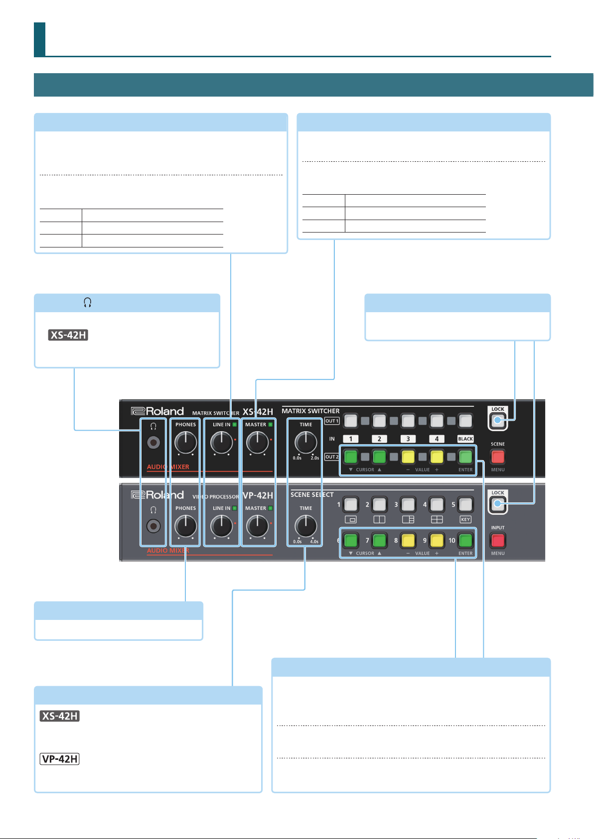
LINE IN
[LINE IN] knob
Adjusts the volume of the line input. Adjust this so that the
LINE indicator is sometimes lit yellow.
LINE IN indicator
Indicates the volume level of the line input.
Lit red
Lit yellow
Lit green
PHONES (
Connect stereo mini-jack headphones here.
5
The output audio is the same as the audio of
the OUTPUT HDMI 1 connector.
Volume is excessive.
Volume is appropriate.
Volume is insucient.
jack
)
MASTER
[MASTER] knob
Adjusts the overall volume.
MASTER indicator
Indicates the overall volume level.
Lit red
Lit yellow
Lit green
Volume is excessive.
Volume is appropriate.
Volume is insucient.
[LOCK] button
Long-press this to turn on/o the panel lock
function.
p. 11
[PHONES] knob
Adjusts the volume of the headphones.
[TIME] knob
Species the transition time when switching between
scenes (p. 9) or video.
Species the transition time when switching between
scenes (p. 9).
p. 8, 9
2
While a menu is displayed
While a menu is displayed, these function as the following buttons.
CURSOR [?] [=] buttons
These buttons select a menu category or item.
VALUE [–] [+] buttons
These buttons change the value of a menu item.
[ENTER] button
This button moves to a lower-level menu, or executes an operation.
p. 6
Page 3
Panel Descriptions
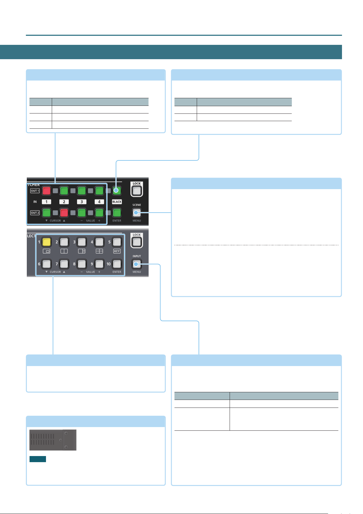
Cross-point [1]–[4] buttons
These buttons switch the cross-point of the video
channel.
Button Status
Lit green Valid video is being input.
Lit red This is the selected video channel.
Dark No video is input.
p. 8
[BLACK] button
p. 8
Fades-out the output video to a black screen.
If you press the cross-point button of a faded-out output, it fades-in.
Button Status
Lit red Faded out
Lit green Normal output
5
You can also fade-out the output video to a still image.
[SCENE]/[MENU] button
p. 6, 9
Scene function: Press the button (lit green)
Turns on the scene function. Recalls a scene (registered video/audio
settings) (p. 9).
5
The cross-point buttons and the [BLACK] button function as scene
select buttons 1–10.
5
The video/audio settings are automatically registered to the currently
selected scene.
SCENE SELECT [1]–[10] buttons
Recall a scene (registered video/audio settings).
5
The video/audio settings are automatically registered to
the currently selected scene.
Cooling vents
NOTE
Do not block the cooling vents. If the cooling vents
are blocked, the temperature inside the unit will rise,
possibly causing malfunctions due to overheating.
(top panel, side panels)
These exhaust internal heat to
prevent the interior of the unit
from overheating.
p. 9
Menu display: Long-press the button (lit red)
The menu is displayed on the monitor connected to the OUTPUT
HDMI 2 connector (p. 6).
While the menu is displayed, each press of the button takes you
back to the next higher level of the menu. If the highest menu level
is already shown, the button closes the menu.
[INPUT]/[MENU] button
p. 6, 8
Video assignment function: Press the button (lit green)
You can use video assignment shortcuts (p. 8). You can use the
SCENE SELECT buttons to select the video assigned to each layer.
SCENE SELECT buttons Explanation
[1]–[4] buttons Select layers 1–4 (when selected: lit yellow)
Select video (when selected: lit red)
[6]–[10] buttons
[6]–[9]: INPUT HDMI 1–4
[10]: Still image
Menu display: Long-press the button (lit red)
The menu is displayed on the monitor connected to the OUTPUT
HDMI 2 connector (p. 6).
While the menu is displayed, each press of the button takes you
back to the next higher level of the menu. If the highest menu level
is already shown, the button closes the menu.
3
Page 4
Panel Descriptions
Rear Panel
* To prevent malfunction and equipment failure, always turn down the volume, and turn o all the units before making any connections.
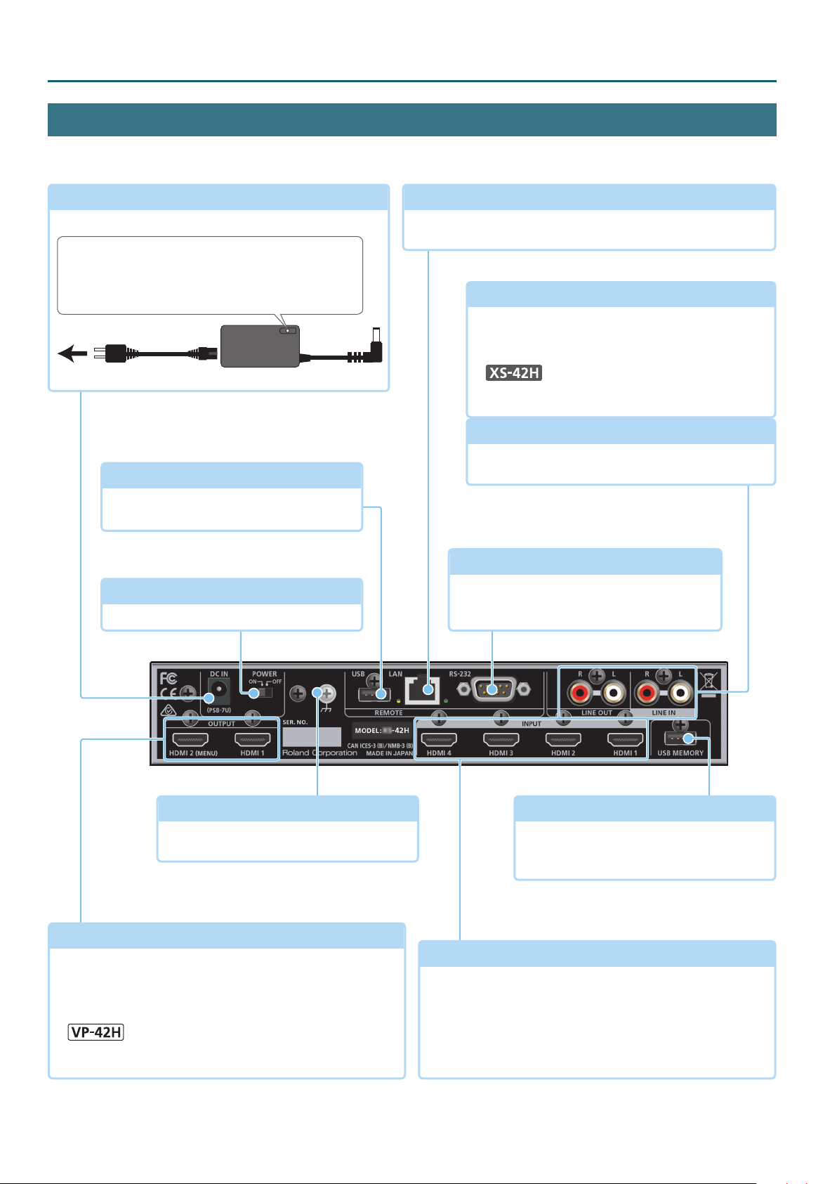
DC IN jack
Connect the included AC adaptor to this jack.
Place the AC adaptor so the side with the indicator faces
upwards and the side with textual information faces
downwards. The indicator will light when you plug the
AC adaptor into an AC outlet.
Power cord
to an AC outlet
AC adaptor
USB port
You can connect a USB ash drive here. This
is used to update the system program.
[POWER] switch
This switch turns the power on/o.
p. 6
LAN port
This is used to remotely control this unit from a web browser or
terminal software.
p. 14, 17, 25
LINE OUT jacks
These output the result of mixing the input audio.
Connect these to your audio recorder, amp, or
speakers etc.
5
The output audio is the same as the audio of the
OUTPUT HDMI 2 connector.
LINE IN jacks
These input audio. Connect these to your audio or
video device such as an audio mixer or CD player.
RS-232 connector
You can connect this to a computer equipped
with an RS-232 connector, and remotely
control this unit.
p. 25
Ground terminal
Connect this to an external earth or ground
if necessary.
OUTPUT HDMI 1, 2 connectors
These output video and audio. Connect them to a projector,
video recorder, or external display.
5
The menu is shown on the monitor connected to the OUTPUT
HDMI 2 connector.
5
The same video is output from the OUTPUT HDMI 1 and 2
connectors.
4
USB MEMORY port
You can connect a USB ash drive here This
is used to load still images or to update the
system program.
p. 10
INPUT HDMI 1–4 connectors
These input video and audio. Connect them to a video device
such as a video camera or BD player, or to a computer.
5
The input format is automatically recognized.
5
In the Input menu, the “Input Status” shows the video format
that is being input to each channel, and the presence or
absence of an HDCP signal.
Page 5
Setup and Preparations
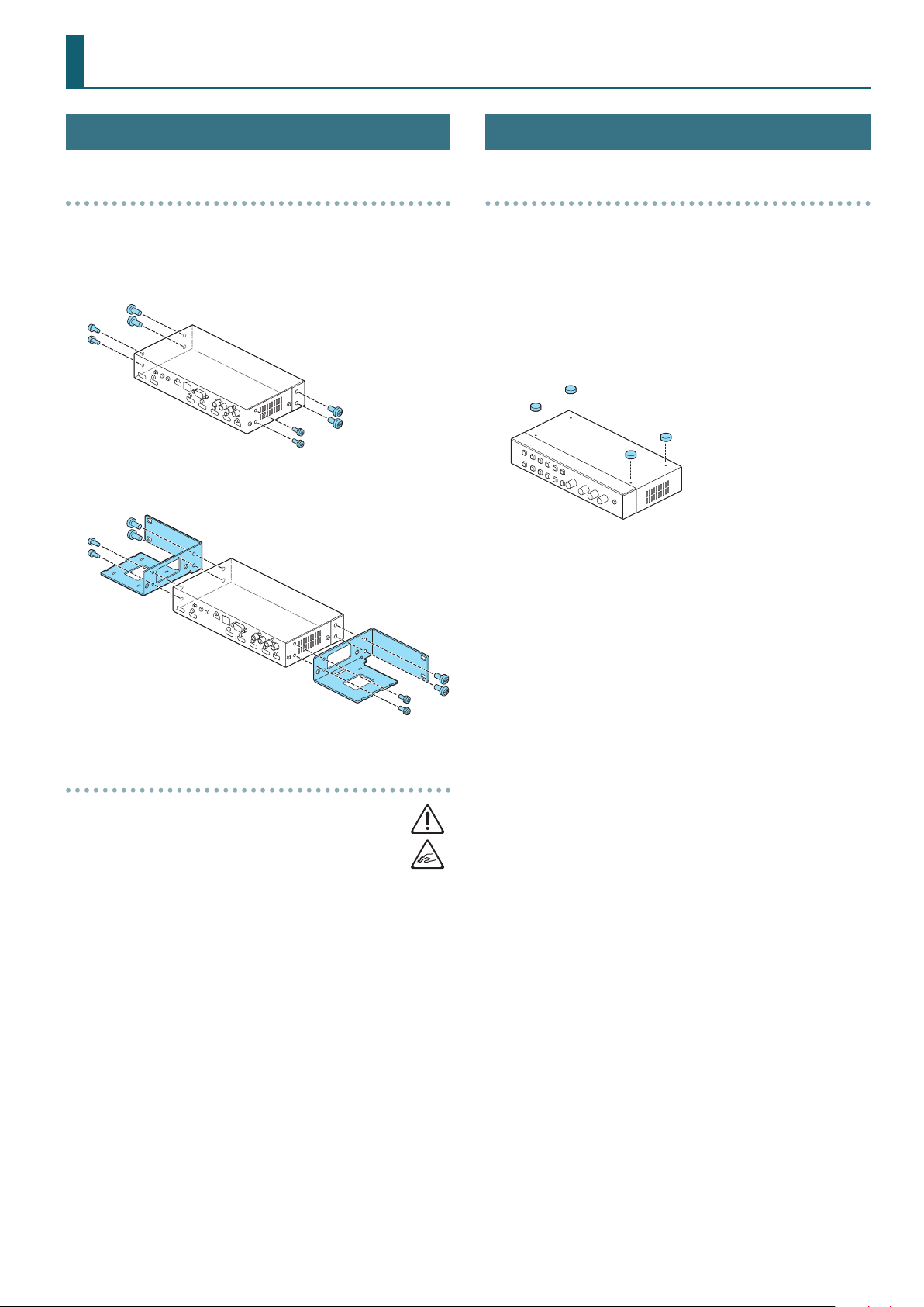
Rack-Mounting
Attaching the rack-mount angles
By attaching the included rack-mount angles to this unit, you can
mount it in a rack.
1. Remove the screws from the side panels.
2. Using the screws that you removed, attach the rack-
mount angles as shown in the illustration.
Free-Standing Use
Attaching the rubber feet
If you will be placing this unit on a desk or shelf for use, attach the
included rubber feet (4 pcs.). This prevents the unit from slipping or
from scratching the surface on which it is placed.
1. Remove the rubber feet from the sheet.
2. Peel the double-sided tape o the rubber feet, and ax
the feet so that they cover the four guide holes on the
bottom of the unit.
Important notes on rack mounting
5
Install in a well-ventilated location.
5
Do not block the cooling vents located on the unit’s top
panel and side panels.
5
Avoid mounting the unit in a sealed-type rack. Warm air within the
rack cannot escape and is sucked into the unit, making ecient
cooling impossible.
5
If the back of the rack cannot be opened, install an exhaust port
or ventilation fan at the top back surface of the rack, where warm
air collects.
5
When using the unit while mounted in a movable case (portable
rack), remove the front and rear rack covers so that the front and
back of the unit are not obstructed.
5
Take care not to pinch your ngers etc. while mounting the unit
in a rack.
5
Page 6
Basic Operation
Turning the Power On/O
* Before turning the unit on/o, always be sure to turn the volume
down. Even with the volume turned down, you might hear some
sound when switching the unit on/o. However, this is normal
and does not indicate a malfunction.
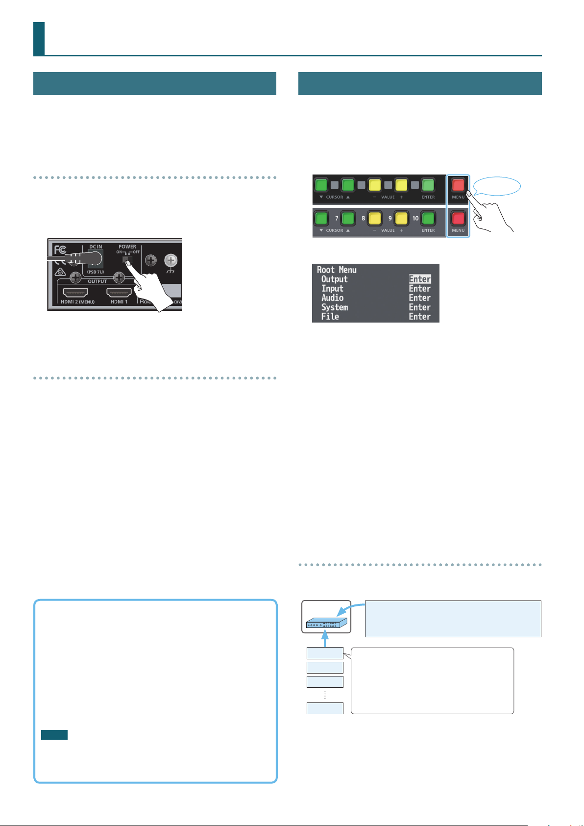
Turning the power on
1. Make sure that all devices are powered-o.
2. To turn on the power, slide this unit’s [POWER] switch to
the ON position.
3. Turn on the power in the order of source devices0
output devices.
Turning the power o
1. Turn o the power in the order of output devices0
source devices.
2. To turn o the power, slide this unit’s [POWER] switch to
the OFF position.
Operating the Menu
Here’s how to access the menu, and make video/audio settings and
settings for this unit.
5
The menu is shown only on the monitor that’s connected to the
OUTPUT HDMI 2 connector.
1. Long-press the [MENU] button to display the menu.
Long-press
The [MENU] button is lit red, and the menu categories are displayed.
2. Press the CURSOR [
then press the [ENTER] button to conrm the selection.
The menu items of the selected category are displayed.
3. Press the CURSOR [
5
If the value area indicates “Enter,” you can press the [ENTER] button
to proceed to a lower level.
Alternatively, pressing the [ENTER] button executes an operation.
5
Pressing the [MENU] button moves you back one level higher.
4. Press the VALUE [–] [+] buttons to change the value of
the setting.
5
By holding down the [ENTER] button and long-pressing the VALUE [–]
or [+] button you can change the value of the setting more greatly.
5
If you press the VALUE [–] and [+] buttons simultaneously, the
selected menu item returns to its default setting.
] [=] buttons to select a category,
?
] [=] buttons to select a menu item.
?
About the Auto O function
The power to the unit turns o automatically when all of the
following states persist for 240 minutes (Auto O function).
5
No operation performed on the unit
5
No audio or video input
5
No equipment is connected to the OUTPUT HDMI connectors
If you do not want the power to be turned o automatically,
disengage the Auto O function. Long-press the [MENU] button
0“System”0set “Auto Power O” to “Disabled.”
NOTE
5
Unsaved data is lost when the power turns o. Before turning
the power o, save the data that you want to keep.
5
To restore power, turn the power on again.
6
5. Press the [MENU] button several times to close the menu.
Saving your settings
With the factory settings, changes you make to menu settings are
automatically saved to the unit when you close the menu.
Unit
Scene 1
Scene 2
Scene 3
Scene 10
5
You can disable automatic saving of the settings. Long-press
the [MENU] button0“System”0set “Auto Setting Store” to
“Disabled.” If automatic storage is disabled, you should manually
store the current settings as necessary (p. 12).
5
For more about scenes, refer to “Recalling Video/Audio Settings
(Scenes)” (p. 9).
Common settings (one setting for the entire unit)
5 System menu
5 Output menu “Color Space,” “Signal Type”
5 Output menu
* Except for “Color Space” and “Signal Type”
5 Input menu
5 Composition menu (VP-42H)
5 Audio menu
5 Cross-point (XS-42H)
Page 7
Video Operations
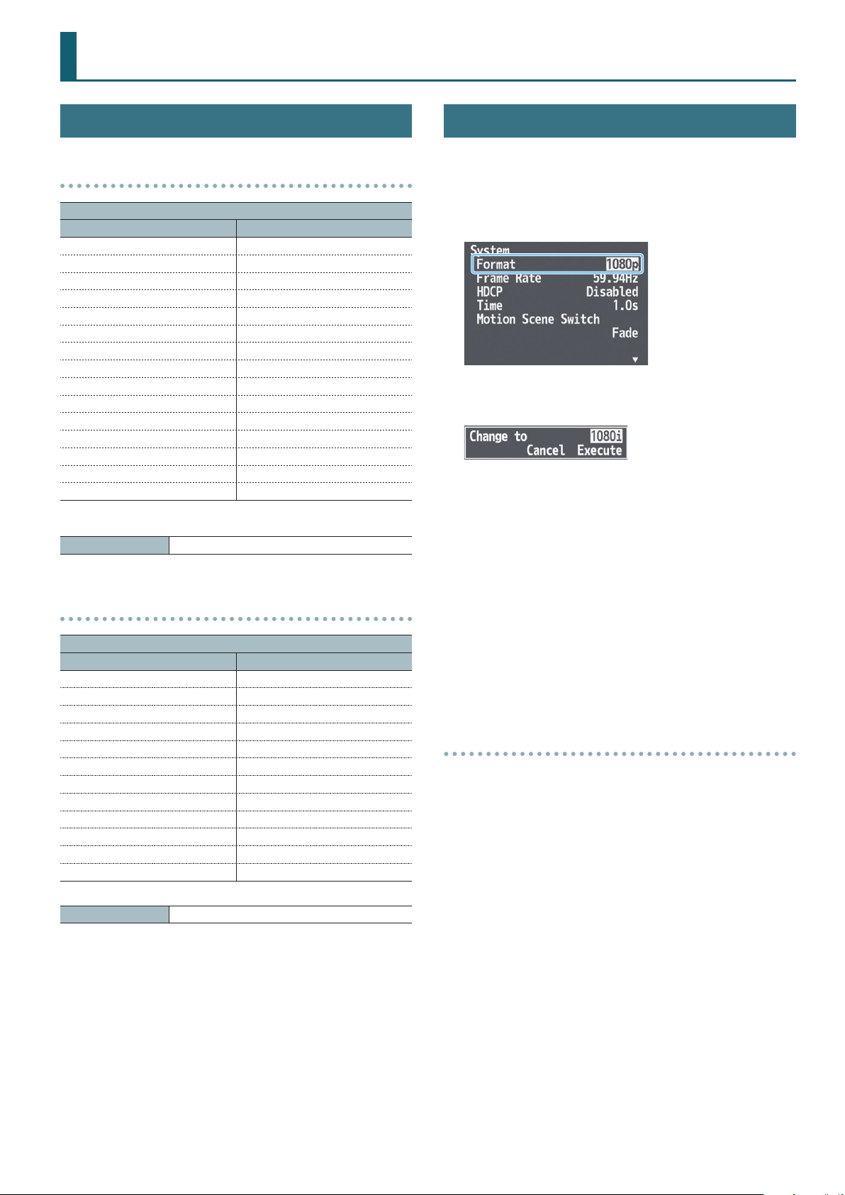
List of Compatible Video Formats
Input video formats
Frame rate
When set to “59.94 Hz” When set to “50 Hz”
480/59.94i 576/50i
480/59.94p 576/50p
720/59.94p 720/50p
1080/59.94i 1080/50i
1080/59.94p 1080/50p
800 x 600/60 Hz 800 x 600/60 Hz
1024 x 768/60 Hz 1024 x 768/60 Hz
1280 x 720/60 Hz 1280 x 720/60 Hz
1280 x 800/60 Hz 1280 x 800/60 Hz
1280 x 1024/60 Hz 1280 x 1024/60 Hz
1366 x 768/60 Hz 1366 x 768/60 Hz
1400 x 1050/60 Hz 1400 x 1050/60 Hz
1600 x 1200/60 Hz 1600 x 1200/60 Hz
1920 x 1080/60 Hz 1920 x 1080/60 Hz
1920 x 1200/60 Hz RB 1920 x 1200/60 Hz RB
* The input format is automatically recognized.
Audio input format HDMI: Linear PCM, 24 bits, 48 kHz, 2 ch
Setting the Output Format
Specify the output format as appropriate for the device that’s
connected.
1. Long-press the [MENU] button
“Format.”
2. Use the CURSOR [
format.
3. Use the CURSOR [
press the [ENTER] button.
The output format switches, and the message “Keep output
format?” appears.
* If your monitor does not support the format, the unit returns to
the previous setting without showing a message.
] [=] buttons to select the output
?
] [=] buttons to select “Execute,” and
?
0
“System” 0 select
Output video formats
Frame rate
When set to “59.94 Hz” When set to “50 Hz”
720/59.94p 720/50p
1080/59.94i 1080/50i
1080/59.94p 1080/50p
1024 x 768/60 Hz 1024 x 768/75 Hz
1280 x 720/60 Hz 1280 x 720/75 Hz
1280 x 800/60 Hz 1280 x 800/75 Hz
1280 x 1024/60 Hz 1280 x 1024/75 Hz
1366 x 768/60 Hz 1366 x 768/75 Hz
1400 x 1050/60 Hz 1400 x 1050/75 Hz
1600 x 1200/60 Hz 1600 x 1200/60 Hz
1920 x 1080/60 Hz 1920 x 1080/60 Hz
1920 x 1200/60 Hz RB 1920 x 1200/60 Hz RB
Audio output format HDMI: Linear PCM, 24 bits, 48 kHz, 2 ch
4. Use the CURSOR [
press the [ENTER] button.
* If you don’t press the [ENTER] button to conrm the setting, you’ll
revert to the original setting without applying the change.
] [=] buttons to select “Yes,” and
?
5. Press the [MENU] button several times to close the menu.
About frame rate
Frame rates that can be input and output are “59.94 Hz” or “50 Hz.”
You can change the frame rate by long-pressing the [MENU] button
0
“System”0 “Frame Rate.”
When inputting Computer-resolution video
The refresh rate is “60 Hz” regardless of the frame rate.
When outputting Computer-resolution video
If the frame rate setting is “50 Hz,” the refresh rate might be “75 Hz”
depending on the output resolution.
7
Page 8
Video Operations
Compositing Video
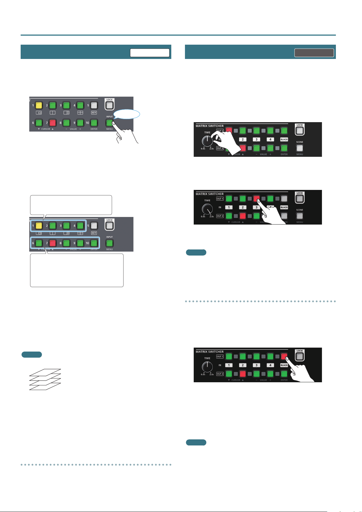
Up to four screens of the video inputs can be composited as layers
and output.
VP-42H only XS-42H only
1. Press the [INPUT] button to make it light green.
Lit green
Now you can use the SCENE SELECT buttons to select the video
that’s assigned to each layer.
5
This is a shortcut for Composition menu0“Layer 1”–“Layer 4”
0
“Source.”
2. Use the SCENE SELECT buttons to select the video that’s
assigned to each layer.
Select a layer 1–4.
The selected button is lit yellow.
Switching the Video
Use the cross-point buttons to switch the combination of four
inputs and two outputs, and output the video. The internal frame
synchronizer allows seamless video switching.
* Video and audio are switched in tandem.
1. Make sure that the [SCENE]/[MENU] button is unlit.
2. Use the [TIME] knob to specify the video transition time.
3. Press a cross-point button.
The horizontal direction of the cross-point buttons is the input
channel, and the vertical direction is the output channel.
Select video.
The selected button is lit red.
[6]–[9] buttons: INPUT HDMI 1–4
[10] button: Still image
5
For details on how to load a still image, refer to “Outputting a
Loaded Still Image” (p. 10).
3. Long-press the [MENU] button
“Layer 1”–“Layer 4”0adjust each of the Window items.
For each layer, adjust the position and size of the video.
0
“Composition”
0
4. Press the [MENU] button several times to close the menu.
MEMO
5
The order in which layers are overlaid is xed.
Layer 1
Layer 2
Layer 3
Layer 4
5
You can use luminance keying to composite the video
that’s assigned to layer 1. Long-press the [MENU] button0
“Composition”0“Layer 1”0set “Key” to “Enabled.” Use “ Type” to
specify the key color.
5
The screen pattern setting is automatically registered in the
currently-selected scene (p. 9).
5
The same video is output from the OUTPUT HDMI 1 and 2
connectors.
Hiding the layers
1. Long-press the [MENU] button
“Layer 1”–“Layer 4”0set “Layer” to “Disabled.”
0
“Composition”
0
The output video is switched.
MEMO
You can individually specify the scaling for each video output.
Long-press the [MENU] button0“Output”0“Output 1”–
“Output 2”0adjust each of the Scaling items.
Fading the Output Video
Here’s how you can fade the output video to a still image or to a black
screen.
1. Press the [BLACK] button of the output channel that you
want to fade-out.
The [BLACK] button is lit red, and the video fades-out to a still
image or a black screen.
2. To fade-in, press the cross-point button of the output
channel that is faded-out.
Video output begins.
MEMO
5
The fade time is specied by the setting of the [TIME] knob.
5
To specify the video source of the [BLACK] button, long-press the
[MENU] button0“Input”0“Input Black”0set “Source.”
For details on how to load a still image, refer to “Outputting a
Loaded Still Image” (p. 10).
8
Page 9
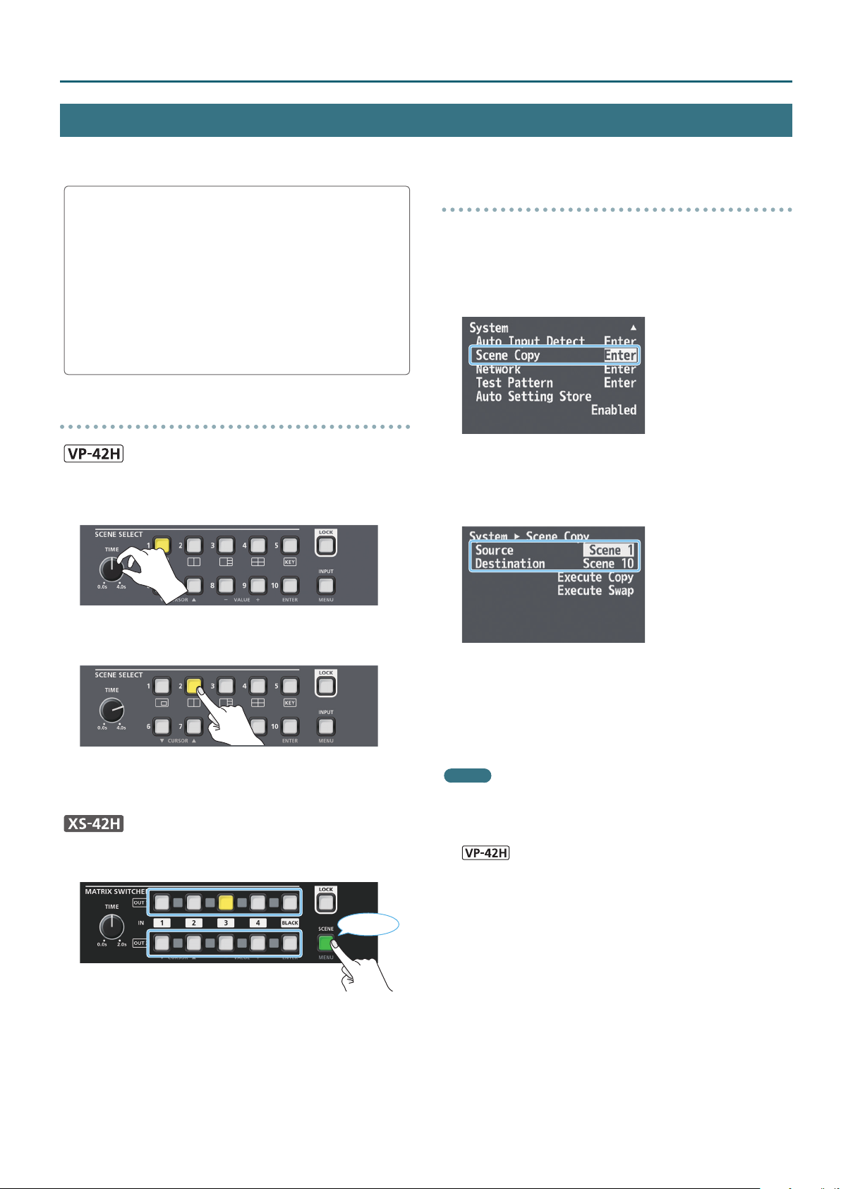
Recalling Video/Audio Settings (Scenes)
Video/audio settings can be registered as “scenes” and recalled for use when necessary. This unit provides ten scenes.
Video Operations
Registering to a scene
Video/audio settings are automatically registered in the currently
selected scene. You don’t need to perform any operation to
register them.
The following settings are registered in a scene.
5
Output menu *
5
Input menu
5
Composition menu (VP-42H)
5
Audio menu
5
Cross-point (XS-42H)
Except for “Color Space” and “Signal Type”
Recalling a scene
1. Make sure that the [INPUT]/[MENU] button is unlit.
2. Use the [TIME] knob to specify the scene switching time.
Copying or exchanging scenes
The settings registered in a scene can be copied to another scene or
exchanged between scenes.
1. Long-press the [MENU] button
“Scene Copy” and press the [ENTER] button.
2. Select “Source” (copy/exchange source scene) and
“Destination” (copy/exchange destination scene),
and use the VALUE [–] [+] buttons to specify the scene
numbers.
0
“System”0select
3. Press the SCENE SELECT button of the scene number that
you want to recall.
The settings are recalled. The currently selected button is lit
yellow.
1. Press the [SCENE] button to make it light green.
SCENE 1–5
Lit green
SCENE 6–10
Now you can use the cross-point buttons and the [BLACK] button
to select a scene. The currently selected button is lit yellow.
3. Choose “Execute Copy” or “Execute Swap,” and press the
[ENTER] button.
The scene is copied or exchanged.
4. Press the [MENU] button several times to close the menu.
MEMO
5
You can change the scene transition eect. Long-press the
[MENU] button0“System”0“Scene Transition,” and specify
“Black,” “Fade,” or “Motion” (VP-42H).
5
You can automatically switch scenes 1–10. Long-press the [MENU]
button0“System”0“Auto Scene Switch” and set the scene
display inter val to “30sec,” “1min,” or “3min.”
2. Press the cross-point button or [BLACK] button of the
scene number that you want to recall.
The settings are recalled.
5
The scene switching time is common with the video switching
time. The setting of the [TIME] knob is used.
9
Page 10
Video Operations
Outputting a Loaded Still Image
A still image that you load from a USB ash drive can be assigned to an input channel, and output in the same way as video.
Formats supported for loading
Format Windows Bitmap File (.bmp), 24-bit color, uncompressed
Resolution Maximum 1920 x 1200 pixels
File name
NOTE
You must specify “default.bmp” as the le name. Still images with
any other le name cannot be loaded.
default.bmp
Loading a still image
Here’s how to load a still image (default.bmp) from a USB ash drive
into this unit.
If a USB ash drive containing a still image (default.bmp) in its
root directory is connected when the unit starts up, the still
image is loaded automatically.
NOTE
5
This unit temporarily saves only the one still image that is loaded.
If a still image is already loaded, loading a new still image
overwrites the previously loaded image. The still image is deleted
when the power is turned o.
5
When using a USB ash drive for the rst time, you must format it
using this unit (p. 12).
5
Never turn o the power or remove the USB ash drive while the
message “Processing.” is shown.
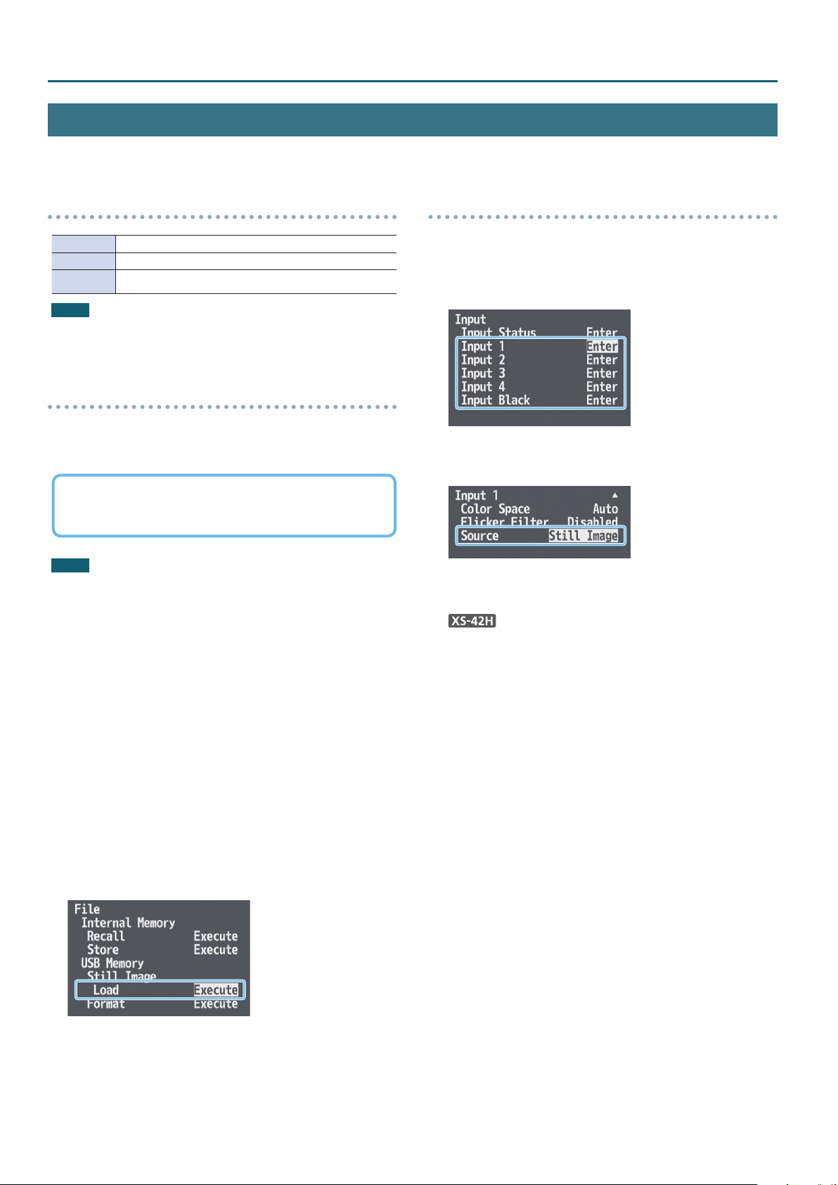
Assigning the still image
Here’s how to assign the loaded still image to an input channel.
1. Long-press the [MENU] button
1”–“Input Black” and press the [ENTER] button.
2. Select “Source,” and use the VALUE [–] [+] buttons to
specify “Still Image.”
If you select the input channel to which “Still Image” is assigned,
the still image is output.
If “Still Image” is assigned to the Input Black channel, pressing the
[BLACK] button fades-out to the still image (p. 8).
3. Press the [MENU] button several times to close the menu.
0
“Input”0select “Input
1. Save the still image (default.bmp) in the root directory of
the USB ash drive.
2. To the USB MEMORY port, connect the USB ash drive on
which the still image is saved.
* Be sure to connect your USB ash drive to the USB MEMORY port.
The USB ash drive is not recognized if it is connected to the USB
port located in the upper row of connectors.
3. Long-press the [MENU] button
select “Load” and press the [ENTER] button.
When the still image has been loaded into the unit, the message
“Completed.” appears.
0
“File”0Still Image,
4. Press the [ENTER] button to close the message.
5. Press the [MENU] button several times to close the menu.
10
Page 11
Audio Operations
Audio Input and Output Settings
You can adjust the volume (Level) of audio that is input or output,
and change the state (State) of each channel.
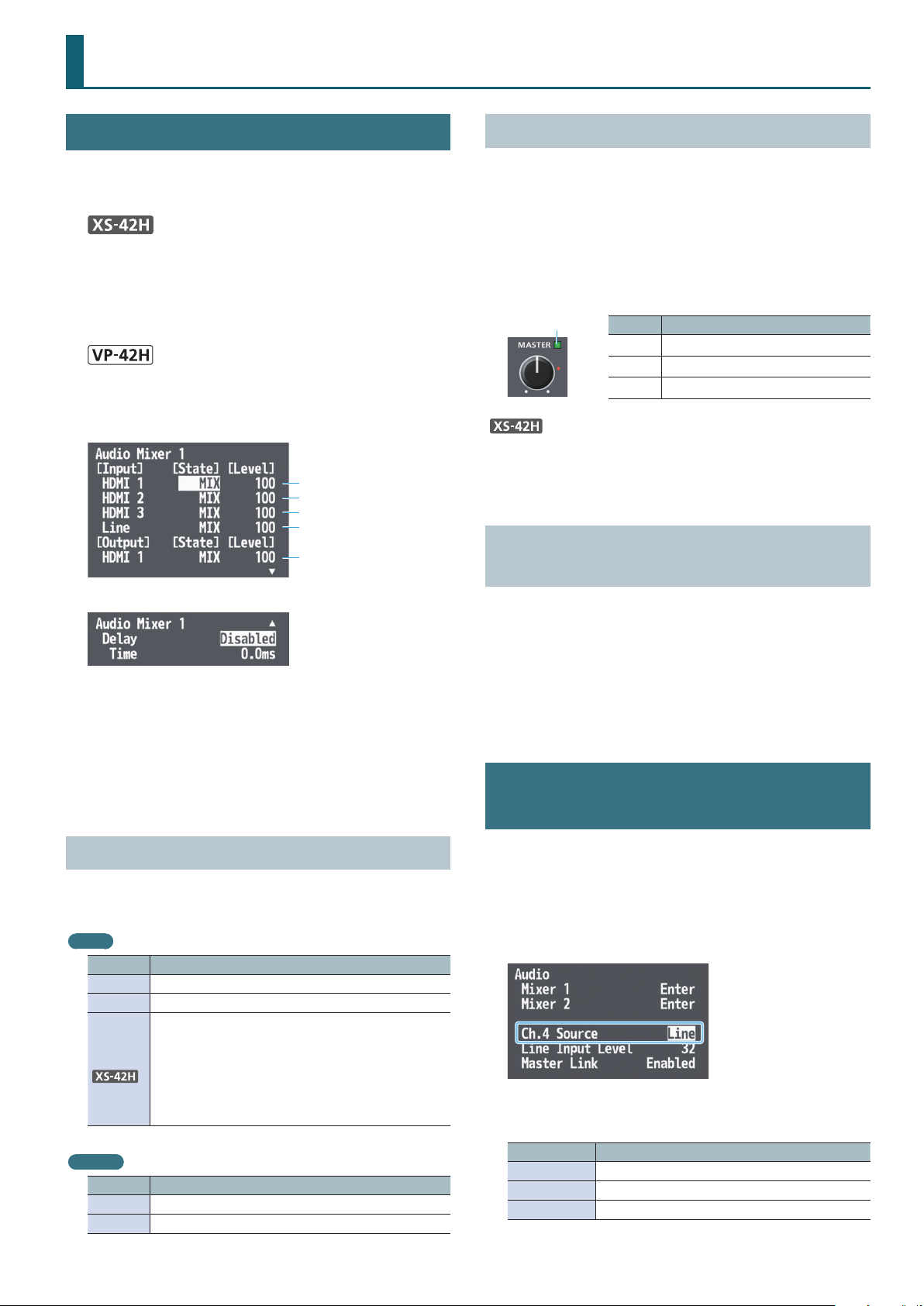
1.
Long-press the [MENU] button0“Audio”0choose
“Mixer 1” (OUTPUT HDMI 1/PHONES) or “Mixer 2” (OUTPUT
HDMI 2/LINE OUT), and press the [ENTER] button.
The XS-42H is equipped with an independent audio mixer for
each output channel.
Long-press the [MENU] button0“Audio”0select
“Mixer” and press the [ENTER] button.
Page 1/2
Input channel 1
Input channel 2
Input channel 3
Input channel 4
Output channel
Adjusting the Volume
(Level)
1. Select the input channel’s “Level,” and adjust the volume.
If there is no input audio, or if you’re not using the audio, set the
volume to “0.”
100 = 0.0 dB, 127 = +6.0 dB.
2. Select the output channel’s “Level,” and adjust the volume.
The color of the MASTER indicator indicates whether the volume
is adjusted appropriately.
Indicator
5
With the factory settings, operating the [MASTER] knob sets the
volume (Level) of OUTPUT HDMI 1 and 2 to the same value.
5
The MASTER indicator shows the volume level of OUTPUT HDMI 1.
Lit color Status
Red Volume is excessive.
Yellow Volume is appropriate.
Green Volume is insucient.
Matching the Output Timing of the Video and
Audio
(Delay)
Page 2/2
2. Use the CURSOR [
] [=] buttons to set each menu item.
?
3. Use the VALUE [–] [+] buttons to change the value of the
setting.
4. Press the [MENU] button several times to close the menu.
Specifying the State of Each Channel
(State)
1. Select the “State” of the input/output channel, and
specify its state.
Input
Value Explanation
MUTE The input audio is temporarily muted (mute function).
MIX The audio is input.
The video and audio switch in tandem (auto follow
function).
FOLLOW
Output
Value Explanation
MUTE The output audio is temporarily muted (mute function).
MIX The result of the audio mix is output.
Audio is output only when an input channel’s cross-point
is selected.
If all input channels are set to “FOLLOW,” only the audio
of the currently selected cross-point is output, and other
audio is muted.
By delaying the output of the audio, you can match the output
timing of the video and audio.
1. Select “Delay ” (page 2/2), and set it to “Enabled.”
2. Select the Delay “Time,” and specify the time by which to
delay the audio.
Selecting the Audio Source of Input Channel 4
Here’s how to select the audio source that is input to input channel 4.
You can also output a test tone.
5
With the factory settings, this is set to “Line” (line input).
1. Long-press the [MENU] button
Source.”
2. Use the VALUE [–] [+] buttons to specify the audio source
that will be input.
Value Explanation
HDMI 4 Input audio from the INPUT HDMI 4 connector
Line Input audio from the LINE IN jacks
Test Tone Test tone
3. Press the [MENU] button several times to close the menu.
0
“Audio”0select “Ch.4
11
Page 12
Other Functions
Manually Saving the Current Settings
If automatic saving of settings is disabled, all the settings you make
are lost when you turn o the power. You can manually save the
current settings as necessary. Saved settings can be recalled and
used.
MEMO
5
To enable/disable automatic saving of settings, long-press the
[MENU] button0“System”0specify “Auto Setting Store.”
5
The unit can store only one set of settings. When you save
settings, the previously saved settings are overwritten.
5
If automatic saving is disabled, the unit starts up with the lastsaved settings the next time you turn on the power.
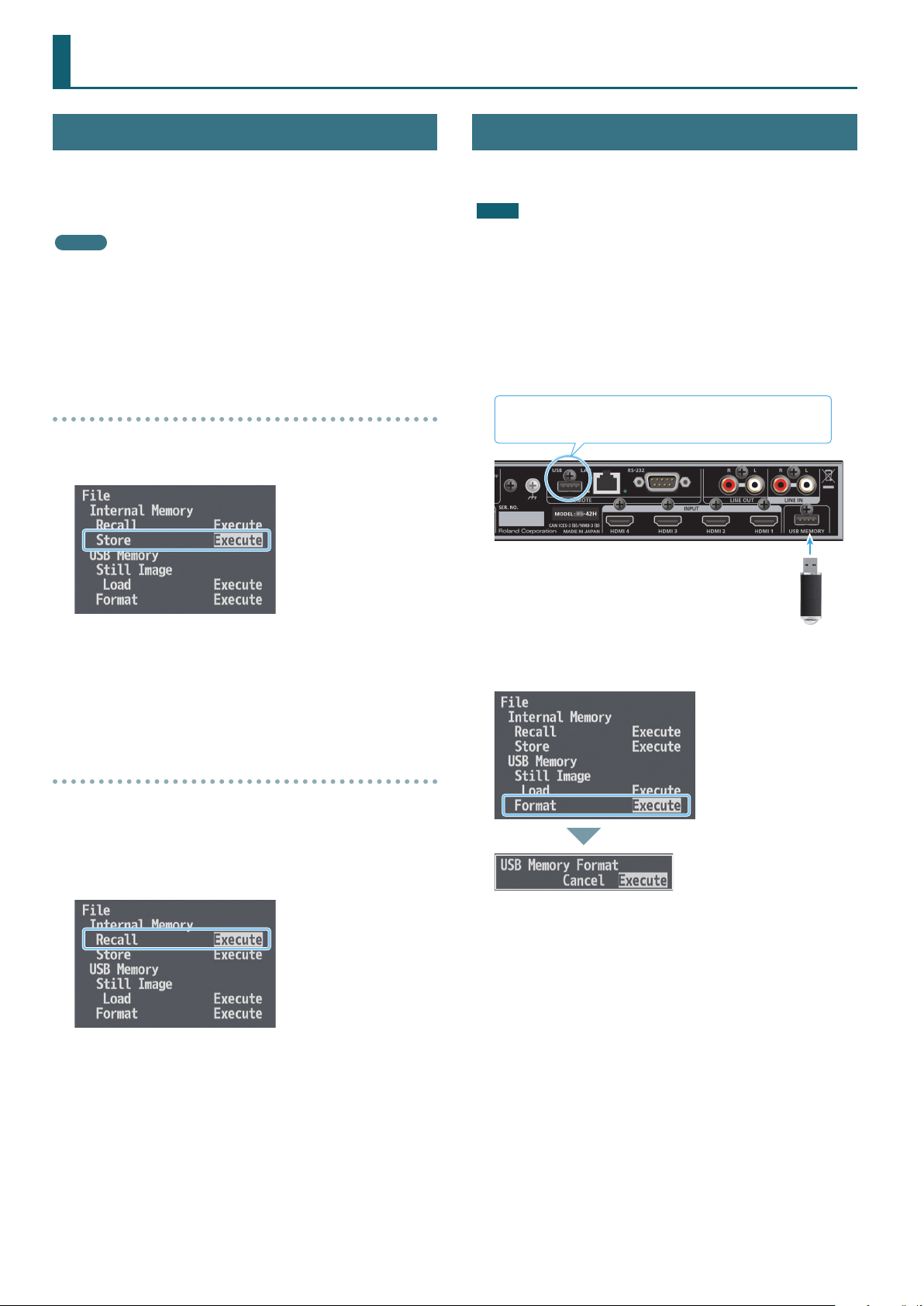
Saving
1. Long-press the [MENU] button
Memory, select “Store” and press the [ENTER] button.
0
“File”0in Internal
Formatting a USB Flash Drive
The rst time that you use a USB ash drive, you must use the unit to
format it.
NOTE
5
A USB ash drive that was not formatted by this unit will not be
recognized.
5
Never turn o the power or remove the USB ash drive while the
message “Processing.” is shown.
5
When you format a USB ash drive, all data on that USB ash drive
is erased. If the drive contains important data, back it up to your
computer before you format the drive.
1. Connect the USB ash drive to the USB MEMORY port.
Even if the USB ash drive is connected to the USB port, it
is not recognized.
* Ensure that the USB ash drive is oriented
correctly, and insert it all the way into the port.
Do not use excessive force.
The current settings are saved. When the operation is nished, the
message “Completed.” appears.
2. Press the [ENTER] button to close the message.
3. Press the [MENU] button several times to close the menu.
Recalling
Here’s how to recall the settings that are saved in the unit. When you
recall the settings, the current settings are overwritten.
1. Long-press the [MENU] button
Memory, select “Recall” and press the [ENTER] button.
The settings are recalled. When the operation is nished, the
message “Completed.” appears.
0
“File”0in Internal
2. Long-press the [MENU] button
Memory, select “Format” and press the [ENTER] button.
3. Use the CURSOR [
press the [ENTER] button.
Formatting is executed. When the operation is nished, the
message “Completed.” appears.
] [=] buttons to select “Execute,” and
?
0
“File”0in USB
A recognition message appears.
4. Press the [ENTER] button to close the message.
5. Press the [MENU] button several times to close the menu.
2. Press the [ENTER] button to close the message.
3. Press the [MENU] button several times to close the menu.
12
Page 13
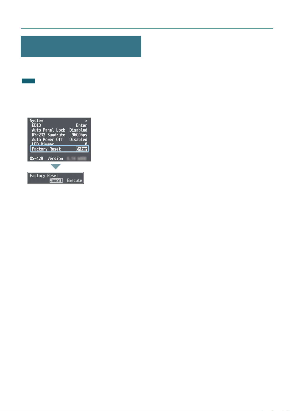
Returning to the Factory Settings (Factory Reset)
Here’s how you can return the settings of the unit to their factory-set
state. If following the procedures described in this manual does not
cause the result you expect, try executing a factory reset.
NOTE
When you execute factory reset, all previously-specied content
and settings registered in scenes (p. 9) are lost.
Other Functions
1. Long-press the [MENU] button
“Factory Reset” and press the [ENTER] button.
2. Use the CURSOR [
press the [ENTER] button.
Factory reset is executed. When the operation is nished, the
message “Completed.” appears.
] [=] buttons to select “Execute,” and
?
0
“System”0select
A recognition message appears.
3. Press the [ENTER] button to close the message.
4. Press the [MENU] button several times to close the menu.
13
Page 14
Network Connections
You can remotely control this unit from a computer or tablet on the network.
Remote control methods
The following two methods of remote control are provided.
Control from a web browser
You can use a web browser such as on your computer to remotely
control the unit’s operating panel and menu settings.
Enter the specied URL in your web browser, and start the WebRCS
web application to control the unit from your web browser.
For details, refer to “WebRCS Web Application” (p. 17).
Control by sending commands
You can send commands from your computer to remotely control the
unit’s operating panel and menu settings.
For details on the commands to transmit, refer to “LAN/RS-232
Command Reference” (p. 25).
Specifying the unit’s network settings
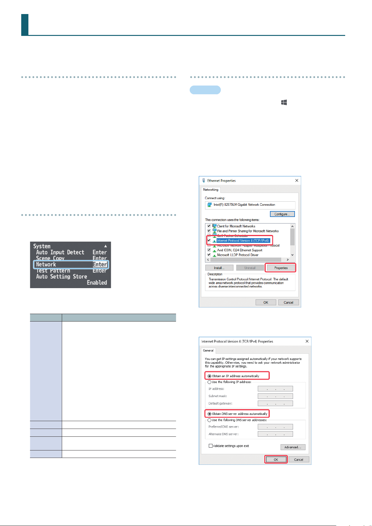
1. Long-press the [MENU] button
“Network” and press the [ENTER] button.
0
“System”0select
Specifying your computer’s network settings
Windows
1. Working in sequence, click the [ (Start)] button
“Settings” (gear icon).
2. Click “Network and Internet.”
3. Click “Change Adapter Options.”
4. Right-click the network connection you’re using, then
click “Properties.”
5. Select “Internet Protocol Version 4 (TCP/IPv4)” and click
the [Properties] button.
0
2. Set the following menu items appropriately for your
network.
Menu item Explanation
Selects how settings are made for the IP address,
subnet mask, and default gateway.
* Changed settings are applied at next start-up.
DHCP Server:
DHCP server functionality is enabled. The information
needed for connecting to the network is assigned
automatically by this unit to the computers that are
IP Congure
IP Address Shows the IP address. (*1) (*2)
Subnet Mask Shows the subnet mask. (*1) (*2)
Default
Gateway
MAC Shows the MAC address.
(*1) Manual settings can be made only if “IP Congure” is set to
“Manually.”
(*2) The identication number “0.0.0.0” is shown until a network
connection is established.
on the LAN.
DHCP Client:
The IP address and other information needed for
connecting to the network is obtained automatically
from the DHCP server of the LAN.
Manually:
The IP address, subnet mask, and default gateway are
specied manually.
Shows the default gateway. (*1) (*2)
6. Select the “Obtain an IP address automatically” and
“Obtain DNS server address automatically” options, and
click the [OK] button.
3. Press the [MENU] button several times to close the menu.
14
Page 15
Network Connections
Mac
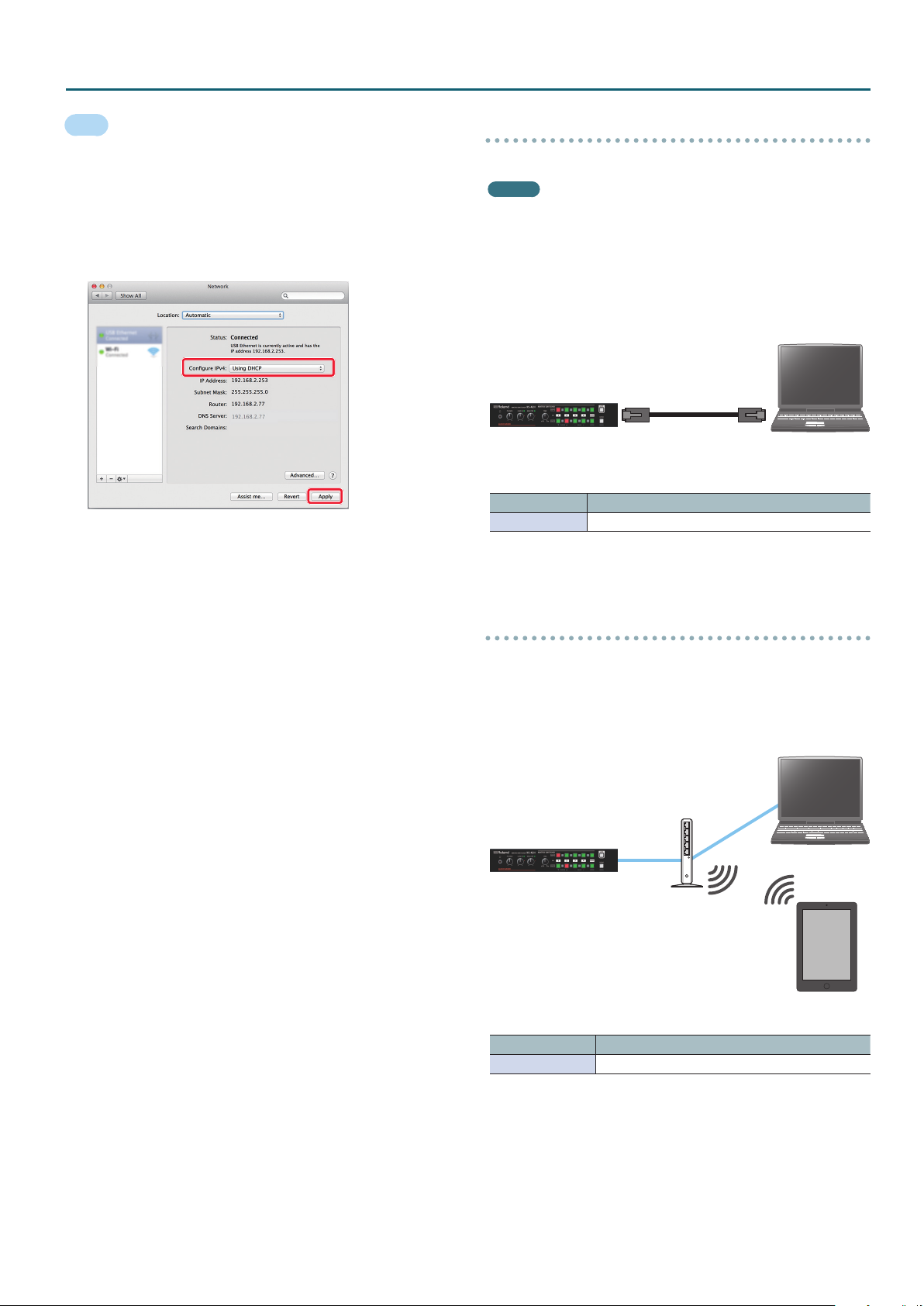
1. Display the Apple menu
0
“System Preferences”0
“Network.”
2. From the list on the left, select the network connection
service you’re using.
3. Set “Congure IPv4” to “Using DHCP,” and click the
[Apply] button.
Connection Example 1
This unit is connected one-to-one to the computer.
MEMO
5
The LAN cable can be either a cross-cable or a straight cable.
5
If your computer does not support a wired LAN, you’ll need to
separately obtain a wired LAN adapter.
5
If you experience problems such as inability to connect when
making a network connection, check whether this unit will
connect one-to-one to your computer.
XS-42H/VP-42H
Network settings on the XS-42H/VP-42H
Menu item Setting
IP Congure DHCP Server
Computer
Connection Example 2
This unit is connected via a router that is equipped with DHCP server
functionality.
DHCP servers are typically sold as routers. Use a router that
is equipped with DHCP server functionality and wireless LAN
conversion functionality.
Computer
Router (DHCP server
functionality)
XS-42H/VP-42H
iPad
Wi-Fi conversion
Network settings on the XS-42H/VP-42H
Menu item Setting
IP Congure DHCP Client
15
Page 16
Network Connections
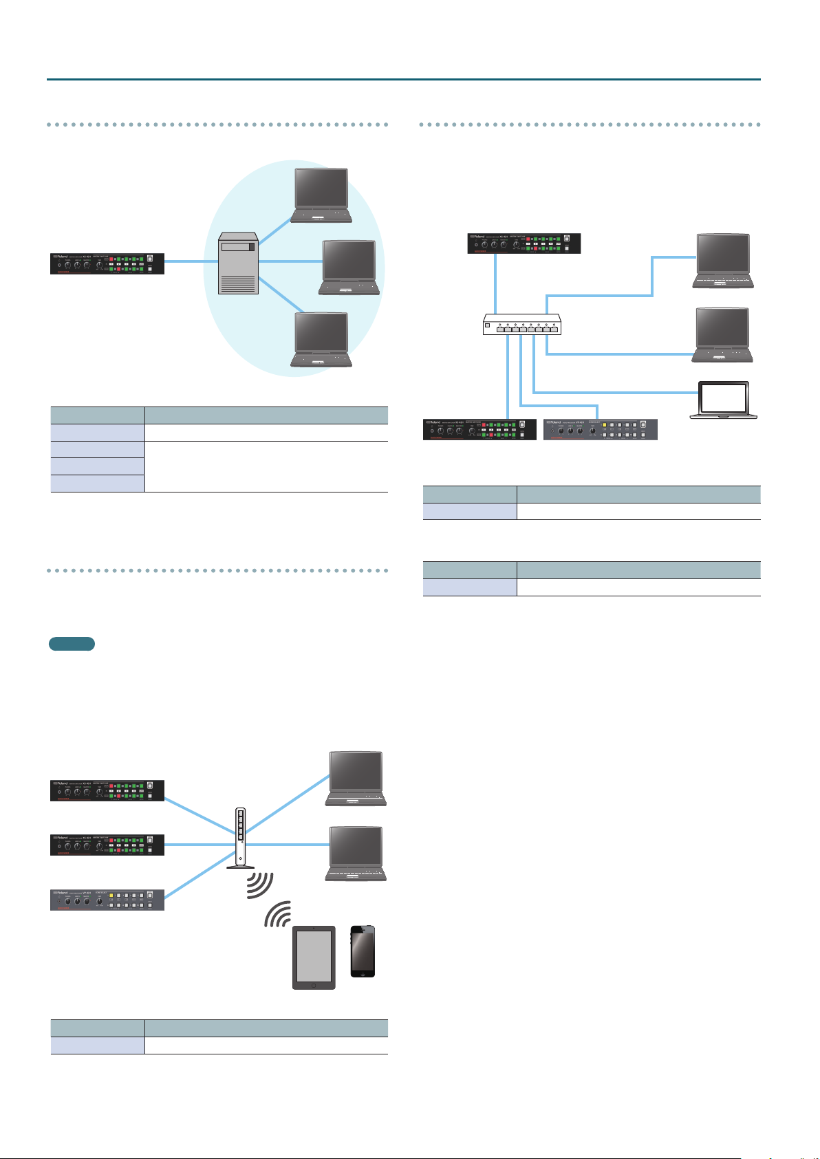
Connection Example 3
This unit is connected to an existing network.
DHCP server
XS-42H/VP-42H
Network settings on the XS-42H/VP-42H
Menu item Setting
IP Congure Manually
IP Address
Subnet Mask
Default Gateway
Input manually.
If you don’t know the required information for the
connection, ask your network administrator.
Usage Example 2
One XS-42H or VP-42H unit is used as the DHCP server, and is
connected to multiple XS-42H/VP-42H units and devices.
You can remotely control the XS-42H/VP-42H units that are specied
as the control destination for each device.
XS-42H
Hub
XS-42H VP-42H
One unit only: XS-42H/VP-42H network settings
Menu item Setting
IP Congure DHCP Server
Computer
Computer
Mac
Usage Example 1
Multiple XS-42H/VP-42H units and devices are connected.
You can remotely control the XS-42H/VP-42H unit that is specied as
the control destination of each device.
MEMO
If you assign a xed IP address to an XS-42H/VP-42H unit, you can
continue using that address as the URL for WebRCS or as the IP
address to which you send commands.
For details on how to specify a xed IP address, refer to the
owner’s manual of the router that you’re using.
Computer
XS-42H
XS-42H
VP-42H
Router (DHCP server
functionality)
Wi-Fi conversion
iPad
Computer
iPhone
Other units: XS-42H/VP-42H network settings
Menu item Setting
IP Congure DHCP Client
Network settings on the XS-42H/VP-42H
Menu item Setting
IP Congure DHCP Client
16
Page 17
WebRCS Web Application
The WebRCS web application is remote control software that is built into this unit. It lets you remotely control this unit’s operating panel and menu
settings from the web browser of a computer or tablet on the network.
There is no need to install special software on your computer or tablet.
Operating requirements
The following web browsers are supported.
Windows Google Chrome 56 or later
Mac
iPhone/iPad Safari 10 or later
Android Google Chrome 56 or later
* Enable JavaScript on the web browser that you’re using.
* The requirements listed above describe systems that have been
found to work; they do not guarantee operation. Operation will
dier due to dierences in your network and the processing
capability of your web browser.
Safari 10 or later
Google Chrome 56 or later
Starting up
1. Long-press the [MENU] button
“Network” and press the [ENTER] button.
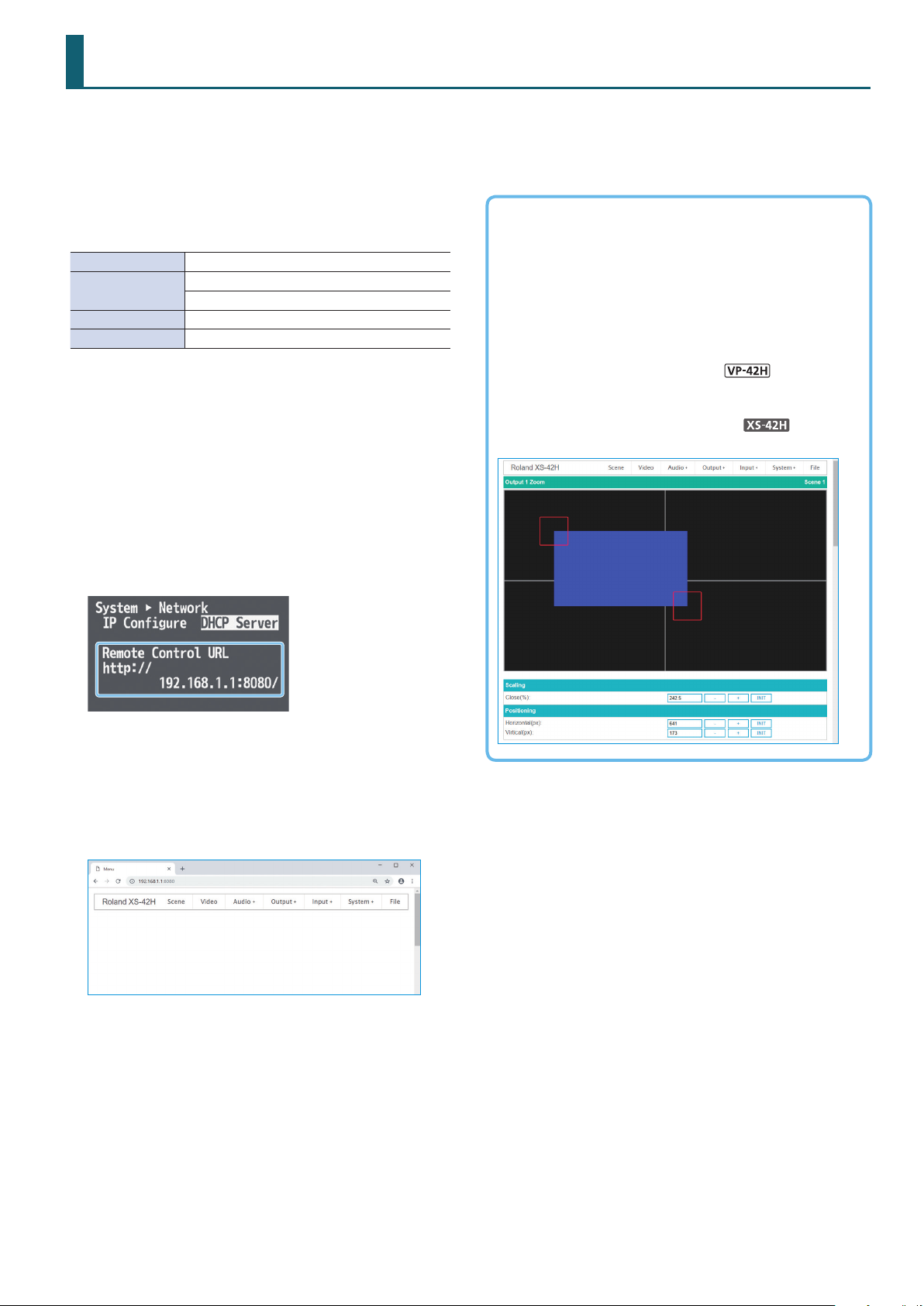
The URL is shown in “Remote Control URL” of the Network menu.
* The URL is not shown if a network connection is not established.
0
“System”0select
Operations that can be performed only via WebRCS
Downloading/uploading the unit’s settings
Choose “File”0“Download” or “Upload.”
This unit’s settings can be downloaded to your computer or other
device as a le.
A downloaded le can be uploaded to this unit to recall the
settings.
Dragging to adjust the layout of a layer
Choose “Composition”0“Layer 1”–“Layer 4.”
Dragging to zoom-in/out the output video
Choose “Output”0“Output 1 Zoom” or “Output 2 Zoom.”
2. Start a web browser on your network-connected
computer or tablet.
3. In the address eld of your web browser, enter the URL
that is shown in “Remote Control URL.”
Start the WebRCS web application; the menu bar appears. Now
you can remotely control this unit from the web browser.
17
Page 18
Menu List
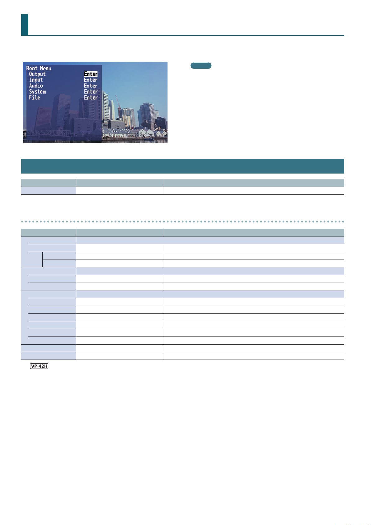
Long-pressing the [MENU] button makes the menu appear on the monitor connected to the OUTPUT HDMI 2 connector.
MEMO
5
By holding down the [ENTER] button and long-pressing the VALUE
[–] or [+] button you can change the value of the setting more
greatly.
5
If you press the VALUE [–] and [+] buttons simultaneously, the
selected menu item returns to its default setting.
Output Menu
Menu item Value (bold text: default value) Explanation
Output 1–2 (Enter) Displays a menu for making detailed settings for Output channel 1–2 (see below).
Output 1–2 detailed settings menu
Menu item Value (bold text: default value) Explanation
Scaling Use the following settings to specify the scaling.
Close 10.0–100.0–1000.0% (*2) Adjusts the zoom ratio.
Horizontal -1920–0– +1920 (*2) Adjusts the size in the horizontal direction.
Fine
Vertical -1200–0– +1200 (*2) Adjusts the size in the vertical direction.
Positioning Use the following settings to adjust the displayed position.
Horizontal -19200–0– +19200 (*2) Adjusts the displayed position in the horizontal direction.
Vertical -12000–0– +12000 (*2) Adjusts the displayed position in the vertical direction.
Color Correction Use the following settings to specify color correction.
Brightness -64–0– +64 Adjusts the brightness.
Saturation -64–0– +64 Adjusts the saturation.
Contrast -64–0– +64 Adjusts the contrast.
Red -64–0– +64 Adjusts the red level.
Green -64–0– +64 Adjusts the green level.
Blue -64–0– +64 Adjusts the blue level.
Color Space RGB 0-255, RGB 16-235, YCC Species the color space.
Signal Type HDMI, DVI-D Species the HDMI output mode.
(*1)
(*2) The range of this value varies according to conditions such as the input/output format. The values listed above are the minimum and maximum values.
The Output 2 menu contains only “Color Space” and “Signal Type.”
(*1)
18
Page 19
Input Menu
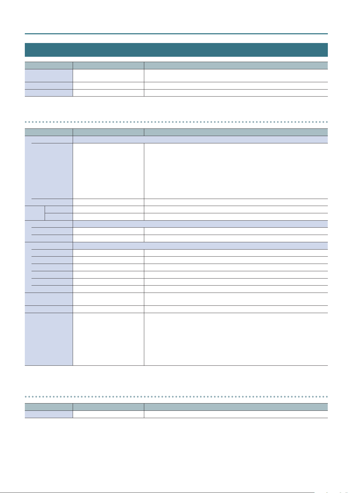
Menu item Value Explanation
Input Status (Enter)
Input 1–4 (Enter) Displays a menu for making detailed settings for Input channel 1–4 (see below).
Input Black (Enter) Displays a menu for making detailed settings for Input Black channel (see below).
Input 1–4 detailed settings menu
Menu item Value (bold text: default value) Explanation
Scaling Use the following settings to specify the scaling.
Type Full, Letterbox, Crop, Dot by Dot
Close 10.0–100.0–1000.0% (*3) Adjusts the zoom ratio.
Horizontal -1920–0– +1920 (*3) Adjusts the size in the horizontal direction.
Fine
Vertical -1920–0– +1920 (*3) Adjusts the size in the vertical direction.
Positioning Use the following settings to adjust the displayed position.
Horizontal -19200–0– +19200 (*3) Adjusts the displayed position in the horizontal direction.
Vertical -12000–0– +12000 (*3) Adjusts the displayed position in the vertical direction.
Color Correction Use the following settings to specify color correction.
Brightness -64–0– +64 Adjusts the brightness.
Saturation -64–0– +64 Adjusts the saturation.
Contrast -64–0– +64 Adjusts the contrast.
Red -64–0– +64 Adjusts the red level.
Green -64–0– +64 Adjusts the green level.
Blue -64–0– +64 Adjusts the blue level.
Color Space
Flicker Filter Disabled, Enabled Enables/disables the icker lter.
RGB 0-255, RGB 16-235, YCC SD,
YCC HD, Auto
Indicates the video format that is being input to each INPUT HDMI connector, and the
presence or absence of an HDCP signal.
Species the scaling type.
Full: Regardless of the aspect ratio of the input video, always show it expanded to
the full screen.
Letterbox: This enlarges or reduces the incoming video to a full-screen view while
keeping the aspect ratio unchanged.
Crop: This enlarges or reduces the incoming video so that the output picture has
no blank margins while keeping the aspect ratio unchanged. Video extending
beyond the borders is cut o.
Dot by Dot: No scaling is performed.
Species the color space.
Species the video source (HDMI input, still image, black screen, share video of another
channel) that is assigned to each input channel.
Menu List
Share video source
Source HDMI, Still Image, Black, Input
(*3) The range of this value varies according to conditions such as the input/output format. The values listed above are the minimum and maximum values.
“Input” can be specied for Input 2–4. The channel you specify will share the video source
of the immediately preceding channel. When you share a video source, one video source is
assigned to multiple channels.
For example, if you want the channel 1 video to be shared by input channels 2–4, set the
input channel 2–4 video source to “Input.”
Input Black detailed settings menu
Menu item Value (bold text: default value) Explanation
Source Still Image, Black Specify the video source (still image, black screen) that is assigned to the Input Black channel.
19
Page 20
Menu List
Composition Menu
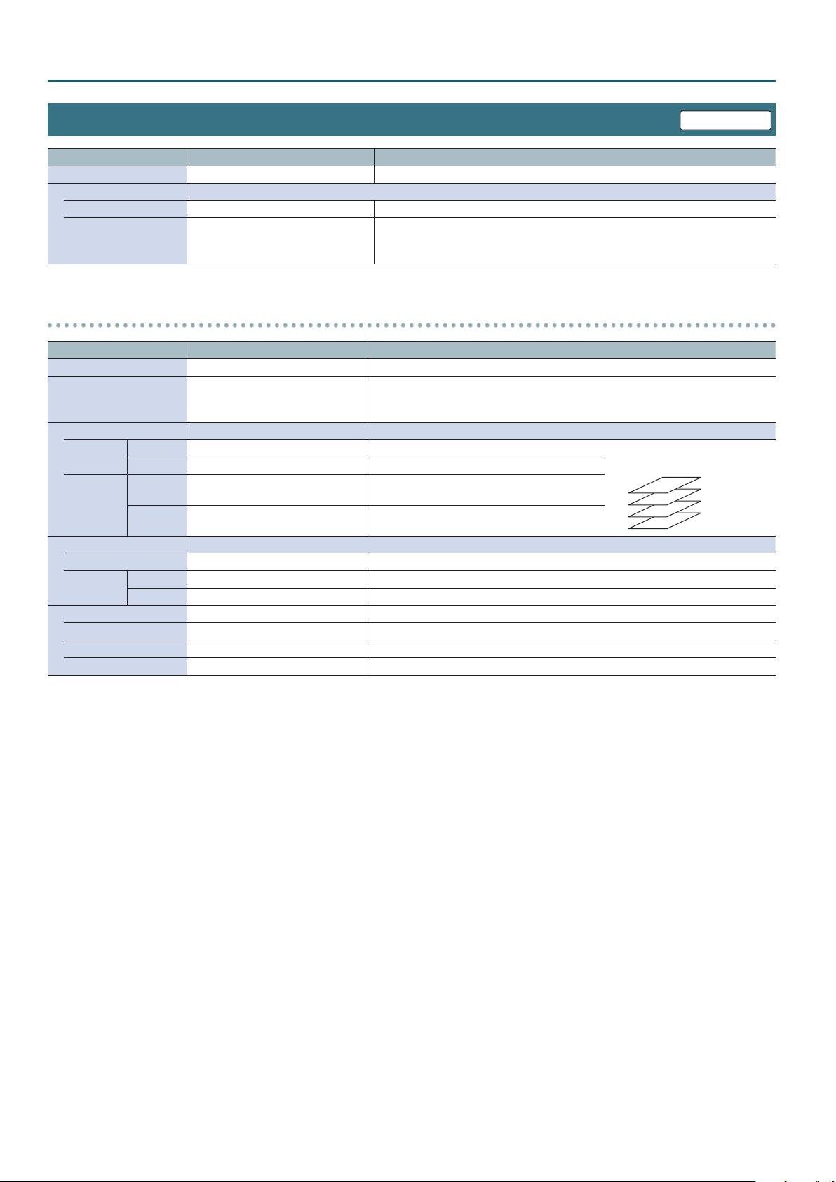
Menu item Value (bold text: default value) Explanation
Layer 1–4 (Enter) Displays the detailed settings menu for each layer (see below).
Layer Copy The following items specify how layer settings are copied or exchanged.
Source Layer 1–4 Species the copy/exchange-source layer number.
Species the copy/exchange-destination layer number.
Destination Layer 1–4
Choose “Execute Copy” or “Execute Swap” and press the [ENTER] button to copy or
exchange the layer settings.
VP-42H only
Layer 1–4 detailed settings menu
Menu item Value (bold text: default value) Explanation
Layer Disabled, Enabled (*4) Shows/hides the layer.
Species the input channel that is assigned to the layer.
Source Input 1–4, Input Black (*4)
Window Use the following items to adjust the layer.
Size
Positioning
View The following items adjust the video that is shown in the layer.
Scaling 10.0–1000.0% (*4) Adjusts the zoom ratio.
Positioning
Key (*5) Disabled, Enabled Enables/disables luminance key compositing.
Type (*5) Luminance Black, Luminance White Species the key color (black or white).
Level (*5) 0–32–127 Adjusts the degree to which the key is removed (transparency).
Gain (*5) 0–4–16 Adjusts the degree to which the edge of the key is blurred (semi-transparent area).
(*4) The default value depends on the scene.
(*5) Shown only for Layer 1.
Horizontal 10.0–100.0% (*4) Adjusts the size in the horizontal direction. * The order in which layers are
Vertical 10.0–100.0% (*4) Adjusts the size in the vertical direction.
Horizontal -100.0–0.0– +100.0% (*4)
Vertical -100.0–0.0– +100.0% (*4)
Horizontal -100.0–0.0– +100.0% Adjusts the displayed position in the horizontal direction.
Vertical -100.0–0.0– +100.0% Adjusts the displayed position in the vertical direction.
* To specify the video source that is assigned to the input channel, use Input menu
0
“Input 1”–“Input 4” or “Input Black”0“Source.”
overlaid is xed.
Adjusts the displayed position in the horizontal
direction.
Adjusts the displayed position in the vertical
direction.
Layer 1
Layer 2
Layer 3
Layer 4
20
Page 21
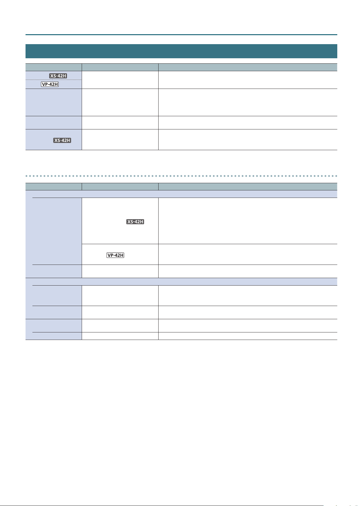
Audio Menu
Menu item Value (bold text: default value) Explanation
Mixer 1, 2
Mixer
Ch.4 Source HDMI 4, Line, Test Tone
Line Input Level 0–32–127
Master Link
Audio Mixer detailed settings menu
Menu item Value (bold text: default value) Explanation
Input
State
Level 0–100–127
Output
State MUTE, MIX
Level 0–32–127
Delay Disabled, Enabled
Time 0–250ms Species the delay time of the output audio.
(Enter) Displays a menu for making detailed settings for the audio mixer (see below).
Species the audio source that is assigned to input channel 4.
HDMI 4: The input audio from the INPUT HDMI 4 connector
Line: The input audio from the LINE IN connector
Test Tone: Test tone
Adjusts the volume of the line input. This can also be adjusted by the [LINE IN] knob.
* 100 = 0.0 dB, and 127 = +6.0 dB.
Species what is operated by the [MASTER] knob.
Disabled, Enabled
MUTE, MIX, FOLLOW
MUTE. MIX
Disabled: Adjusts the OUTPUT HDMI 1 volume.
Enabled: Links OUTPUT HDMI 1 and 2, and adjusts them to the same volume.
Species the state of the input channel.
MUTE: The input audio is temporarily muted (mute function)
MIX: The audio is input.
FOLLOW: The video and audio switch in tandem (auto follow function).
Audio is output only when an input channel’s cross-point is selected.
If all input channels are set to “FOLLOW,” only the audio of the currently
selected cross-point is output, and other audio is muted.
Species the state of the input channel.
MUTE: The input audio is temporarily muted (mute function)
MIX: The audio is input.
Adjusts the volume of the input audio.
* 100 = 0.0 dB, and 127 = +6.0 dB.
Species the state of the output channel.
Mute: The output audio is temporarily muted (mute function).
Mix: The result of the audio mix is output.
Adjusts the volume of the output audio.
* 100 = 0.0 dB, and 127 = +6.0 dB.
If this is set to “Enabled,” the delay time specied by “Time” (see below) is applied to the
output audio.
Menu List
21
Page 22
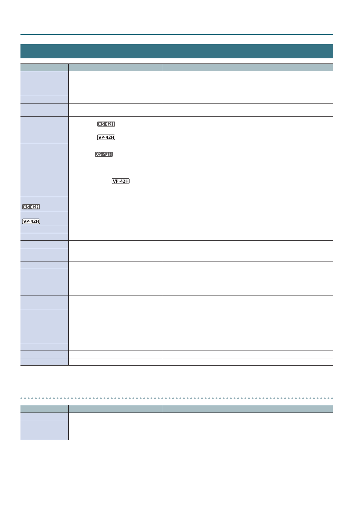
Menu List
System Menu
Menu item Value (bold text: default value) Explanation
720p, 1080i, 1080p, 1024 x 768, 1280 x 720,
Format
Frame Rate 59.94, 50Hz Species the frame rate.
HDCP Disabled, Enabled
Time
Motion Scene Switch
Auto Input Detect
1280 x 800, 1366 x 768, 1280 x 1024,
1400 x 1050, 1600 x 1200, 1920 x 1080,
1920 x 1200
0.0–1.0–2.0s
0.0–1.0–4.0s
Black, Fade
Black, Fade, Motion
(Enter) Displays the auto input detect detailed settings menu (p. 23).
Species the output format.
If this is set to “Enabled,” copy-protected (HDCP) video can be input. Also, HDCP is
applied to the video that is output.
Species the transition time when switching between scenes or video. This can also
be adjusted by the [TIME] knob.
Species the transition time when switching between scenes. This can also be
adjusted by the [TIME] knob.
Species what happens when scenes are switched.
Black: A fade eect enclosing a black screen is applied.
Fade: A fade eect is applied.
Species what happens when scenes are switched.
Black: A fade eect enclosing a black screen is applied. All layers switch
simultaneously.
Fade: A fade eect is applied. Layers switch individually.
Motion: The window of each layer moves as the switch occurs.
Auto Scene Switch
Scene Copy (Enter) Displays the scene copy detailed settings menu (see below).
Network (Enter) Displays the network detailed settings menu (p. 24).
Test Pattern (Enter) Displays the test pattern detailed settings menu (p. 22).
Auto Setting Store Disabled, Enabled
EDID (Enter) Displays the EDID copy detailed settings menu (p. 24).
Auto Panel Lock Disabled, Enabled
RS-232 Baudrate 9600, 38400bps
Auto Power O Disabled, Enabled
LED Dimmer 1–8 Adjusts the brightness of the front panel LEDs.
Factory Reset (Enter) Resets the unit to its factory-set state.
Version — Displays the system program version.
Disabled, 30sec, 1min, 3min Species the display interval when scenes are switched automatically.
If this is “Enabled,” the current settings are automatically saved to the unit when you
close the menu.
Enables/disables the auto panel lock function. If this is “Enabled,” the unit starts up
with the panel locked (the [LOCK] button is lit red).
To disable panel lock, long-press the [LOCK] button.
* A change to this setting is applied at the next start-up.
Species the communication speed (bps) of the RS-232 connector).
* A change to this setting is applied at the next start-up.
Enables/disables the auto-o function. If this is set to “Enabled,” the power
automatically turns o when 240 minutes elapse with the unit in the following state.
5 No operation performed on the unit
5 No audio or video input
5 No equipment is connected to the OUTPUT HDMI connectors
Scene Copy detailed settings menu
Menu item Value (bold text: default value) Explanation
Source Scene 1–10 Species the copy/swap-source scene number.
Species the copy/swap-destination scene number.
Destination Scene 1–10
22
When you choose “Execute Copy” or “Execute Swap” and press the [ENTER] button,
the scenes are copied or swapped.
Page 23
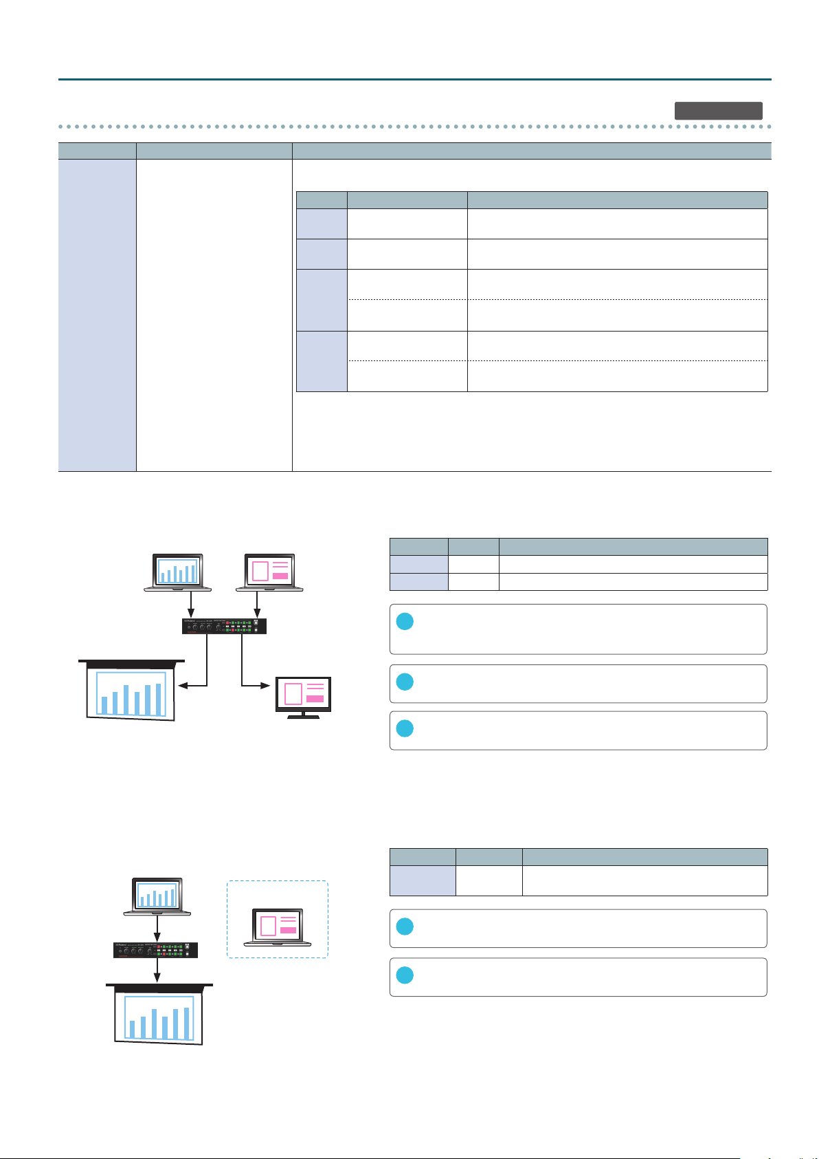
Menu List
Auto Input Detect detailed settings menu
Menu item Value (bold text: default value) Explanation
Species the mode of the auto input detect function. When the signal input disappears, this function
automatically switches to an input that has a signal.
Mode Detection Operation
Mode 1a
Mode 1b
Mode 2a
Mode 2b
Operation common to all modes
While the Input Black channel (black screen or still image) is being output, if a signal input is detected
on any input channel 1–4, the unit switches to the channel for which a signal is being input.
* If you pressed the [BLACK] button to output the Input Black channel, the video will not switch even
when a signal input is detected on an input channel 1–4.
Output 1, 2
Disabled, Mode 1a, Mode 1b,
Mode 2a, Mode 2b
Detects that the signal
input has disappeared
Detects that the signal
input has disappeared
Detects a signal input
from a state of no signal
Detects that the signal
input has disappeared
Detects a signal input
from a state of no signal
Detects that the signal
input has disappeared
Consecutively scans from input channel 1, and switches to an
input that has a signal.
Switches to the Input Black channel (black screen or still image).
Switches to the channel that is inputting a signal.
Consecutively scans from input channel 1, and switches to an
input that has a signal.
Switches to the channel that is inputting a signal.
Switches to the Input Black channel (black screen or still image).
XS-42H only
Setting example 1) In a presentation, switch between the computers of multiple presenters
This allows you to check the readiness or preview the screen of the next presenter, and smoothly switch from the computer of the current presenter.
“Auto Input Detect” settings
Current presenter Next presenter
Menu item Value Target
Output 1 Mode 1a Main auditorium monitor, current presenter’s computer
Output 2 Mode 2a Preview monitor, next presenter’s computer
When you connect the next presenter’s computer, the computer screen
1
OUTPUT HDMI 1 OUTPUT HDMI 2
Main auditorium monitor
Preview monitor
is shown in the preview monitor, allowing you to check the computer’s
readiness and screen.
When you disconnect the current presenter’s computer, the next
2
presenter’s computer screen is shown on the main auditorium monitor.
When you further connect the next presenter’s computer, the computer
3
screen is shown on the preview monitor.
Setting example 2) In a conference room that has a single main monitor, change connections between the computers of dierent presenters
The XS-42H holds the output signal when you connect a dierent computer, thus preventing a state in which the monitor shows no signal or a
blue screen, or goes to sleep.
“Auto Input Detect” settings
Current presenter
Next presenter
OUTPUT HDMI 1
Main monitor
Menu item Value Target
Output 1
When you disconnect the current presenter’s computer, the unit switches
1
to the Input Black channel (black screen or still image).
When you connect the next presenter’s computer, the computer’s screen is
2
shown on the main monitor.
If you connect the next presenter’s computer while the current presenter’s
computer is connected
Mode 1b: The input does not switch. In this state if you disconnect the current
Mode 2b: The unit switches to the screen of the next presenter’s computer.
Mode 1b or
Mode 2b
presenter’s computer, the unit switches to the Input Black channel
(black screen or still image).
Main monitor, current presenter’s computer
23
Page 24
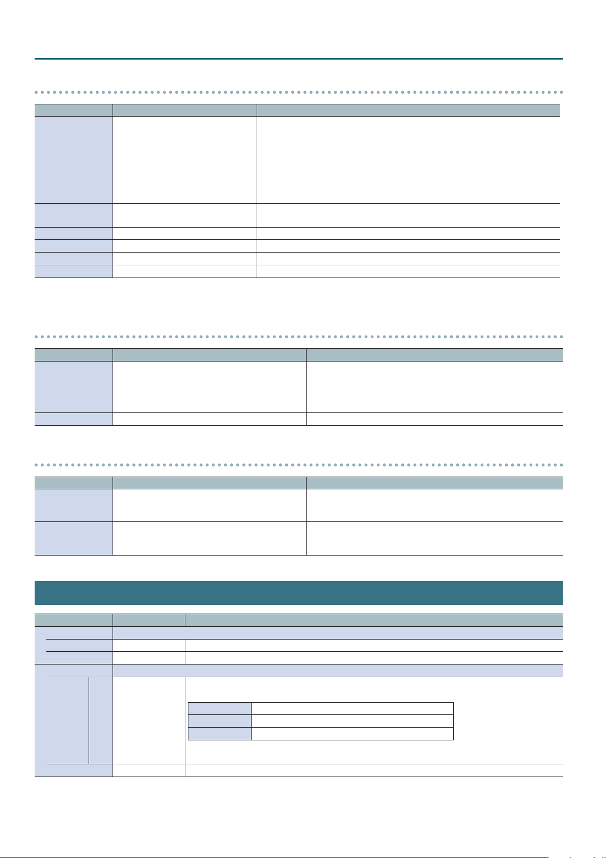
Menu List
Network detailed settings menu
Menu item Value (bold text: default value) Explanation
Selects how settings are made for the IP address, subnet mask, and default gateway.
* Changed settings are applied at next start-up.
DHCP Server: DHCP server functionality is enabled. The information needed for
IP Congure DHCP Server, DHCP Client, Manually
DHCP Client: The IP address and other information needed for connecting to the
Manually: The IP address, subnet mask, and default gateway are specied manually.
Remote Control URL
IP Address 192.168.10.10 (example display) Shows the IP address. (*6) (*7)
Subnet Mask 255.255.255.0 (example display) Shows the subnet mask. (*6) (*7)
Default Gateway 192.168.10.1 (example display) Shows the default gateway. (*6) (*7)
MAC 00:00:00:00:00:00 (example display) Shows the MAC address.
(*6) Manual settings can be made only if “IP Congure” is set to “Manually.”
(*7) The identication number “0.0.0.0” is shown until a network connection is established.
http://192.168.10.10:8080/
(example display)
Shows the URL for starting the WebRCS web application in your web browser.
* The URL is not shown if a network connection is not established.
connecting to the network is assigned automatically by this unit to the
computers that are on the LAN.
network is obtained automatically from the DHCP server of the LAN.
Test Pattern detailed settings menu
Menu item Value (bold text: default value) Explanation
Disabled, Color Bars SMPTE, Color Bars 75%,
Pattern
Motion Disabled, Slow, Fast Species the scroll speed of the test pattern.
Color Bars 100%, Ramp, Step, Hatch, Frame, Diagonal,
Circle, Red, Green, Blue, white, Black, ColorBars 75%-SP,
Color Bars100%-SP, Ramp-SP, Step-SP, Hatch-SP,
Ver.Stripe, Hor.Stripe, Ver.Stripe-RB, Hor.Stripe-RB
Species the test pattern.
EDID detailed settings menu
Menu item Value (bold text: default value) Explanation
Source
Destination Input 1–4
Default, 720p, 1080i, 1080p, 1024 x 768, 1280 x 720,
1280 x 800, 1366 x 768, 1280 x 1024, 1400 x 1050,
1600 x 1200, 1920 x 1080, 1920 x 1200
Species the EDID copy source.
Species the copy-destination INPUT HDMI connector.
When you select “Execute” and press the [ENTER] button, the EDID
information is copied.
File Menu
Menu item Value Explanation
Internal Memory Settings for the following items are manually saved and recalled.
Recall (Execute) Press the [ENTER] button to recall the settings saved in the unit.
Store (Execute) Press the [ENTER] button to store the current settings in the unit’s internal memory.
USB Memory The following items execute operations using a USB ash drive.
Loads a still image saved in the USB ash drive’s root directory into the unit.
Formats supported for loading
Format Windows Bitmap File (.bmp), 24-bit color, uncompressed
Still Image Load (Execute)
Format (Execute) Formats the USB ash drive.
Resolution Maximum 1920 x 1200 pixels
File name default.bmp
* If a USB ash drive containing a still image (default.bmp) in its root directory is connected when the unit
starts up, the still image is loaded automatically.
24
Page 25
LAN/RS-232 Command Reference
The unit support two types of remote-interface communication: LAN and RS-232.
Using the LAN port or RS-232 connector to send specic commands to the unit from a controlling device lets you operate the unit remotely.
LAN Interface
This uses the LAN port on the unit.
You use Telnet to operate the unit remotely over a LAN (TCP/IP
protocol).
Communication standards
Port LAN port (supports 100BASE-TX)
TCP port number 8023
For methods of connecting to a network, refer to “Network
Connections” (p. 14).
RS-232 Interface
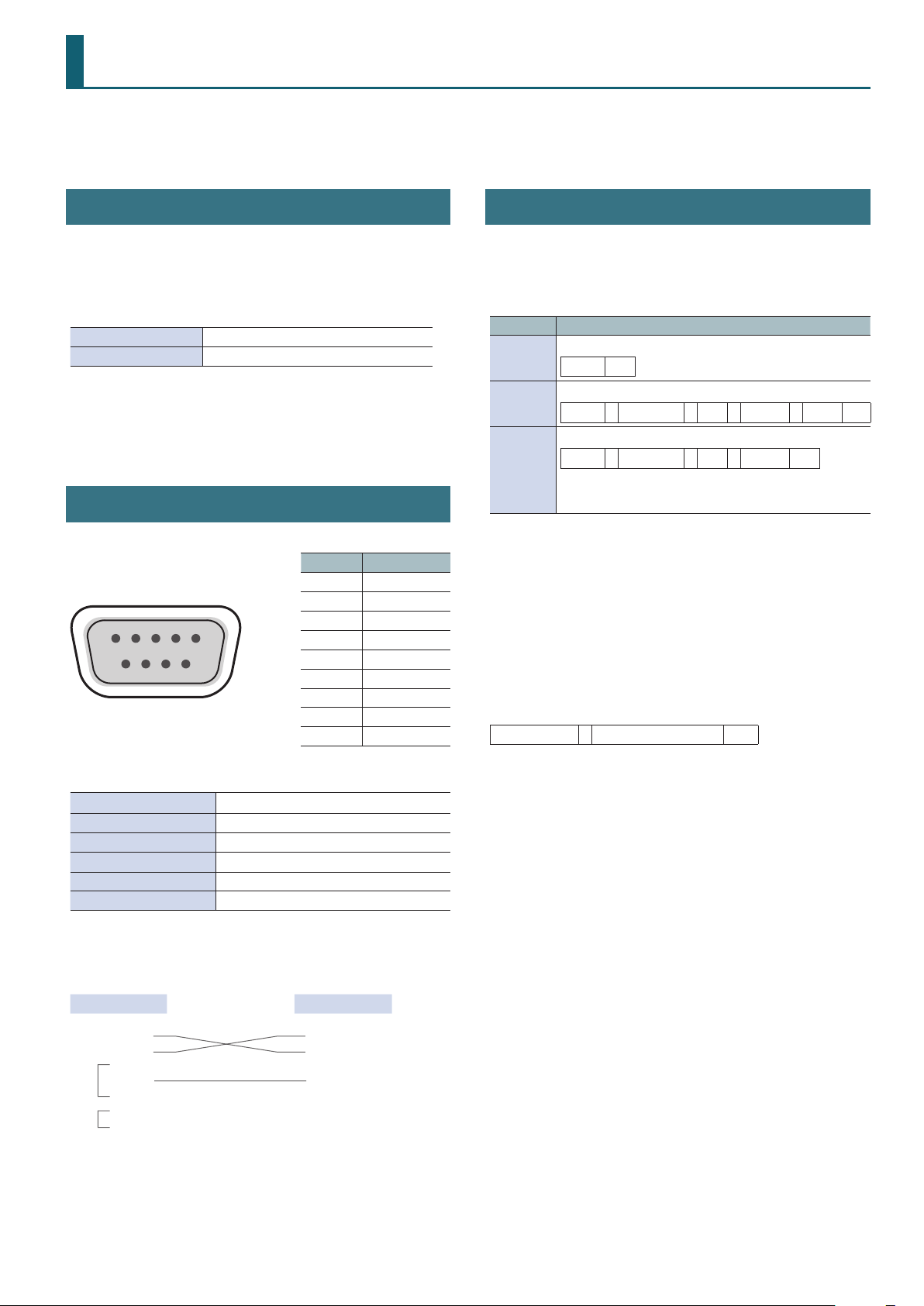
RS-232 connector pin layout Pin assignments
Pin No. Signal
1 N.C.
2 RXD
3 TXD
1 2 3 4 5
6 7 8 9
DB-9 type (male)
4 DTR
5 GND
6 DSR
7 RTS
8 CTS
9 N.C.
Command Format
Commands are common to the LAN and the RS-232 interface.
Transmitted commands (control device0this unit)
Transmit specic commands from the control device to this unit.
Command Format
Obtains the model name and version information.
ver
set
get
* “lf” is the ASCII code “0aH,” and is a control code that indicates the
end of the command. H indicates a hexadecimal value.
ack response (this unit0control device)
When this unit correctly receives a command, it returns ack.
The ack response commands are described in “List of Commands”
(p. 26).
Error response (this unit0control device)
When this unit could not correctly receive a command, it returns an
error.
err , Transmitted command lf
ver lf
Sets a parameter.
set , Category , ID , Sub-ID , Value lf
Obtains the current parameter value.
get , Category , ID , Sub-ID lf
When this unit correctly receives a command, it returns
set,[category],[ID],[sub-ID],[value][lf].
Communication standards
Communication method Synchronous (asynchronous), full-duplex
Communication speed 9,600/38,400 bps
Parity none
Data length 8 bits
Stop bit 1 bit
Code set ASCII
Cable wiring diagram
Use an RS-232 crossover cable to connect the unit and the controller
(an RS-232-compatible computer or other device).
This unit Control device
N.C.: 1 1:
RXD: 2 2: RXD
TXD: 3 3: TXD
DTR: 4 4:
GND: 5 5: GND
DSR: 6
RTS: 7 7:
CTS: 8
N.C.: 9
(Crossover connection)
* The connections between 4 and 6 and between 7 and 8 are inside
the unit.
6:
8:
9:
25
Page 26
LAN/RS-232 Command Reference
List of Commands
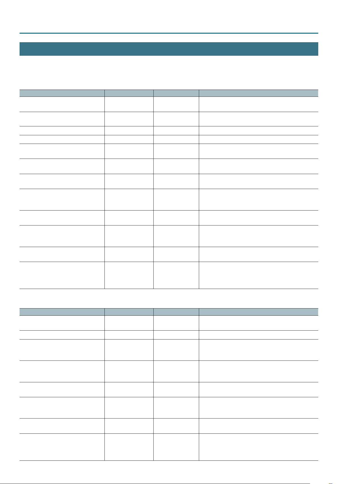
* When sending a sequence of commands to the unit from a controller, after each one, be sure to verify that an “ack” response is returned before
sending the next command.
XS-42H
Item Transmitted command Response command Parameter
Specify the video/scene transition time set,10,19,0,[a][lf ] ack,10,19,0,[a][lf] a: 0–4,000
* The units are milliseconds (ms).
Switch scenes set,11,11,0,[a][lf] ack,11,11,0,[a][lf ] a: 0 (Scene 1)–9 (Scene 10)
Select the input channel for OUTPUT 1 set,11,10,0,[a][lf ] ack,11,10,0,[a][lf] a: 0 (Input 1)–3 (Input 4), 4 (Input Black)
Select the input channel for OUTPUT 2 set,11,10,1,[a][lf ] ack,11,10,1,[a][lf] a: 0 (Input 1)–3 (Input 4), 4 (Input Black)
Obtain the current scene number get,10,20,0[lf ] ack,10,20,0[lf]
set,10,20,0,[a][lf]
Obtain the input channel currently
selected for OUTPUT 1
Obtain the input channel currently
selected for OUTPUT 2
Adjust the input channel volume of Audio
Mixer 1
Adjust the overall volume of Audio Mixer 1 set,[a],2,0,[b][lf] ack,[a],2,0,[b][lf] a: 0 (Scene 1)–9 (Scene 10)
Adjust the input channel volume of Audio
Mixer 2
Adjust the overall volume of Audio Mixer 2 set,[a],9,0,[b][lf] ack,[a],9,0,[b][lf] a: 0 (Scene 1)–9 (Scene 10)
Acquire version information ver[lf ] ack,ver[lf]
get,[a],0,0[lf] ack,[a],0,0[lf]
set,[a],0,0,[b][lf]
get,[a],0,1[lf] ack,[a],0,1[lf]
set,[a],0,1,[b][lf]
set,[a],1,[b],[c][lf] ack,[a],1,[b],[c][lf] a: 0 (Scene 1)–9 (Scene 10)
set,[a],8,[b],[c][lf] ack,[a],8,[b],[c][lf] a: 0 (Scene 1)–9 (Scene 10)
ver,XS-42H,[a][lf ]
a: 0 (Scene 1)–9 (Scene 10)
a: 0 (Scene 1)–9 (Scene 10)
b: 0 (Input 1)–3 (Input 4), 4 (Input Black)
a: 0 (Scene 1)–9 (Scene 10)
b: 0 (Input 1)–3 (Input 4), 4 (Input Black)
b: 0 (Input 1)–3 (Input 4)
c: 0–127
b: 0–127
b: 0 (Input 1)–3 (Input 4)
c: 0–127
b: 0–127
a: Version
* The version info is ASCII text strings.
* If this unit is in the process of starting up, the version is
shown as “----.”
VP-42H
Item Transmitted command Response command Parameter
Specify the scene transition time set,10,19,0,[a][lf] ack,10,19,0,[a][lf ] a: 0–4,000
* The units are milliseconds (ms).
Switch scenes set,11,11,0,[a][lf] ack,11,11,0,[a][lf ] a: 0 (Scene 1)–9 (Scene 10)
Show/hide a layer set,[a],43,[b],[c][lf ] ack,[a],43,[b],[c][lf] a: 0 (Scene 1)–9 (Scene 10)
b: 0 (Layer 1)–3 (Layer 4)
c: 0 (Disabled), 1 (Enabled) Show/hide a layer
Specify the input channel assigned to a
layer
Obtain the current scene number get,10,20,0[lf ] ack,10,20,0[lf]
Adjust the input channel volume set,[a],1,[b],[c][lf] ack,[a],1,[b],[c][lf] a: 0 (Scene 1)–9 (Scene 10)
Adjust the overall volume set,[a],2,0,[b][lf] ack,[a],2,0,[b][lf ] a: 0 (Scene 1)–9 (Scene 10)
Acquire version information ver[lf ] ack,ver[lf]
26
set,[a],44,[b],[c][lf] ack,[a],44,[b],[c][lf ] a: 0 (Scene 1)–9 (Scene 10)
b: 0 (Layer 1)–3 (Layer 4)
c: 0 (Input 1)–3 (Input 4), 4 (Input Black)
a: 0 (Scene 1)–9 (Scene 10)
set,10,20,0,[a][lf]
b: 0 (Input 1)–3 (Input 4)
c: 0–127
b: 0–127
a: Version
ver,VP-42H,[a][lf ]
* The version info is ASCII text strings.
* If this unit is in the process of starting up, the version is
shown as “----.”
Page 27
Appendices
Troubleshooting
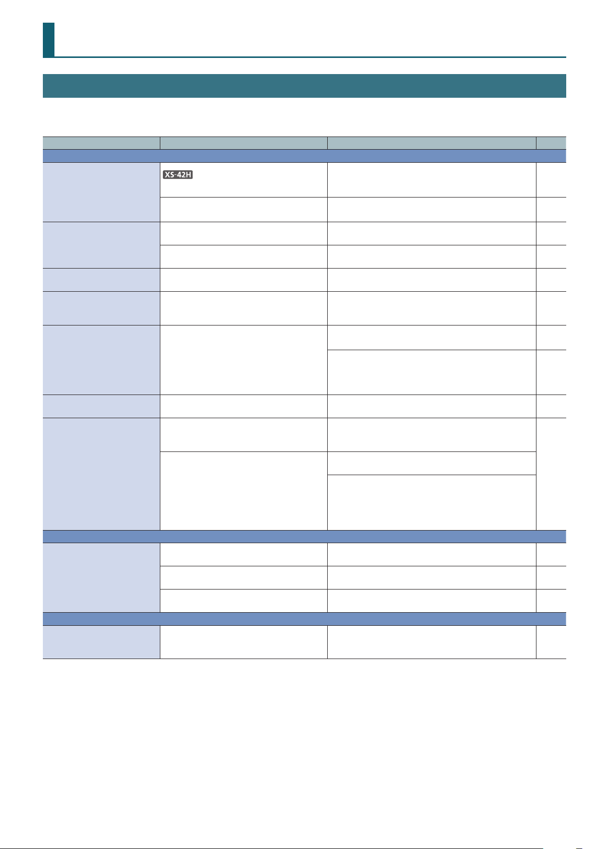
If you suspect a malfunction, please check the following points.
If this does not resolve the problem, contact a nearby Roland Service Center.
Problem Items to check Action Page
Video-related problems
Video of a format not supported by the unit being input.
No picture is input.
Video is not output.
“Snowy”-noise video is
output.
Video input from a computer
is distorted.
Color is wrong.
An edge of the video shown
on a display is cut o.
Can’t load a still image.
Audio-related Problems
No audio is output.
Audio volume is low.
Other Problems
Can’t use a USB ash drive.
Could the cross-point buttons be unlit?
Could you be inputting copy-protected
(HDCP) video?
Is the display connected correctly?
Do the color space settings of the outputdestination device and the unit match?
It might be that the HDMI signal is not being
correctly transmitted or received.
If video is being input from a computer, the
image can sometimes be skewed, ickering,
or otherwise distorted.
Do the color space settings of the outputdestination device and the unit match?
Are the display’s settings correct?
Are you loading a still image of a format and
resolution supported by the unit?
Is the le name of the still image assigned
correctly?
Could the volume setting of the connected
amp or speaker be low?
Could the volume setting be lowered?
Could the audio be muted (silenced)?
Has the USB ash drive been formatted by
the unit?
If valid video is being input, the crosspoint button is lit
green.
If you want to input copy-protected (HDCP) video, set
the System menu “HDCP” setting to “Enabled.”
If you want to output copy-protected (HDCP) video,
connect a HDCP-compliant display.
Go to Output menu0 “Output 1”–”Output 2”0and
change the “Color Space” setting.
Reconnect the HDMI cable. —
This is a phenomenon called “tearing,” and is not a
malfunction.
Go to Output menu0 “Output 1”–”Output 2”0and
change the “Color Space” setting.
Depending on the device, the color space might be
linked with the DVI/HDMI selection or the selection of
format. If so, changing the color space of the outputdestination device might solve the problem.
Depending on the display, it might overscan
automatically. Change the settings of the device.
Still images of an unsupported format or resolution are
not recognized. Make sure that the still image is of a
format and resolution that are supported by the unit.
Specify “default.bmp” as the le name. If the le’s name is
not correct, it is not recognized.
If you assign a le name on your computer, and the
computer is set to hide the le name extension, the
extension might be duplicated so that the name is
“default.bmp.bmp.”
Check the settings of your computer.
Adjust the volume appropriately. —
Adjust each input audio setting to the appropriate
volume. Also adjust the overall volume.
In the Audio menu, set “State” to “MIX” or “FOLLOW”
(XS-42H) so that muting is disabled.
A USB ash drive that was not formatted by the unit is
not recognized. When using a USB ash drive for the rst
time, you must format it on this unit.
p. 7
—
—
—
—
—
—
—
p. 10
—
p. 11
p. 12
27
Page 28
Appendices
INPUT 1
HDMI 1
STILL IMAGE
BLACK
SCALER
COLOR
CORRECTOR
FRAME
SYNCHRONIZER
INPUT 2
HDMI 2
STILL IMAGE
BLACK
SCALER
COLOR
CORRECTOR
FRAME
SYNCHRONIZER
INPUT 3
HDMI 3
STILL IMAGE
BLACK
SCALER
COLOR
CORRECTOR
FRAME
SYNCHRONIZER
INPUT 4
HDMI 4
STILL IMAGE
BLACK
SCALER
COLOR
CORRECTOR
FRAME
SYNCHRONIZER
INPUT BLACK
STILL IMAGE
BLACK
OUTPUT 1
Common output format
to Audio Follow 1
to Audio Follow 2
MENU
HDMI
COLOR CORRECTORSCALER
OUTPUT 2
HDMI
SCALER COLOR CORRECTOR
TEST PATTERN
SWITCHER
MUTE FOLLOWLEVEL MIX1 MIX2
METER
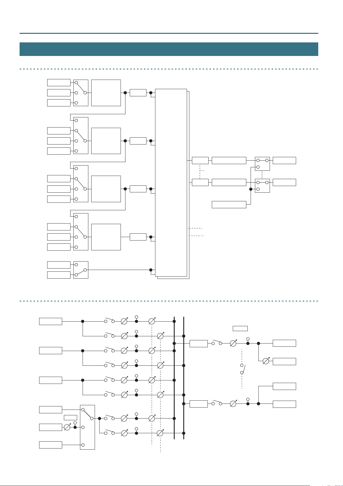
XS-42H Block Diagram
Video section
INPUT 1
INPUT 2
INPUT 3
INPUT 4
HDMI 1
STILL IMAGE
BLACK
HDMI 2
STILL IMAGE
BLACK
HDMI 3
STILL IMAGE
BLACK
HDMI 4
STILL IMAGE
BLACK
FRAME
SYNCHRONIZER
COLOR
CORRECTOR
FRAME
SYNCHRONIZER
COLOR
CORRECTOR
FRAME
SYNCHRONIZER
COLOR
CORRECTOR
FRAME
SYNCHRONIZER
COLOR
CORRECTOR
SCALER
SCALER
SCALER
SCALER
SCALER
SWITCHER
SCALER
COLOR CORRECTOR
Common output format
COLOR CORRECTOR
to Audio Follow 1
to Audio Follow 2
TEST PATTERN
HDMI
HDMI
OUTPUT 1
OUTPUT 2
MENU
INPUT BLACK
Audio section
INPUT 1
INPUT 2
INPUT 3
INPUT 4
STILL IMAGE
HDMI
HDMI
HDMI
HDMI
LINE
-10 dBu
BLACK
LINE IN
LEVEL
DELAY
MAX: 250 ms
DELAY
MAX: 250 ms
MUTE
MUTE
MASTER
LEVEL METER
Link
LEVEL METER
LEVEL
HDMI
PHONES
LINE
-10 dBu
HDMI
OUTPUT 1
OUTPUT 2
28
TEST TONE
L: 1 kHz
R: 2 kHz
Ch.4
Input Select
from Video Switcher 1
from Video Switcher 2
Page 29
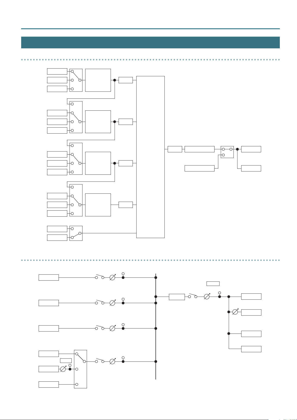
VP-42H Block Diagram
INPUT 1
HDMI 1
STILL IMAGE
BLACK
SCALER
COLOR
CORRECTOR
FRAME
SYNCHRONIZER
INPUT 2
HDMI 2
STILL IMAGE
BLACK
SCALER
COLOR
CORRECTOR
FRAME
SYNCHRONIZER
INPUT 3
HDMI 3
STILL IMAGE
BLACK
SCALER
COLOR
CORRECTOR
FRAME
SYNCHRONIZER
INPUT 4
HDMI 4
STILL IMAGE
BLACK
SCALER
COLOR
CORRECTOR
FRAME
SYNCHRONIZER
INPUT BLACK
STILL IMAGE
BLACK
OUTPUT 1
MENU
HDMI
COLOR CORRECTORSCALER
OUTPUT 2
TEST PATTERN
HDMI
COMPOSITOR
MUTE LEVEL MIX
METER
Video section
Appendices
INPUT 1
INPUT 2
INPUT 3
INPUT 4
INPUT BLACK
Audio section
HDMI 1
STILL IMAGE
BLACK
HDMI 2
STILL IMAGE
BLACK
HDMI 3
STILL IMAGE
BLACK
HDMI 4
STILL IMAGE
BLACK
STILL IMAGE
BLACK
FRAME
SYNCHRONIZER
COLOR
CORRECTOR
FRAME
SYNCHRONIZER
COLOR
CORRECTOR
FRAME
SYNCHRONIZER
COLOR
CORRECTOR
FRAME
SYNCHRONIZER
COLOR
CORRECTOR
SCALER
SCALER
SCALER
SCALER
COMPOSITOR
SCALER
COLOR CORRECTOR
TEST PATTERN
HDMI
HDMI
OUTPUT 1
OUTPUT 2
MENU
INPUT 1
INPUT 2
INPUT 3
INPUT 4
HDMI
HDMI
HDMI
HDMI
LINE
-10 dBu
TEST TONE
L: 1 kHz
R: 2 kHz
LINE IN
LEVEL
Ch.4
Input Select
DELAY
MAX: 250 ms
MUTE
MASTER
LEVEL METER
LEVEL
HDMI
PHONES
LINE
-10 dBu
HDMI
OUTPUT 1
OUTPUT 2
29
Page 30
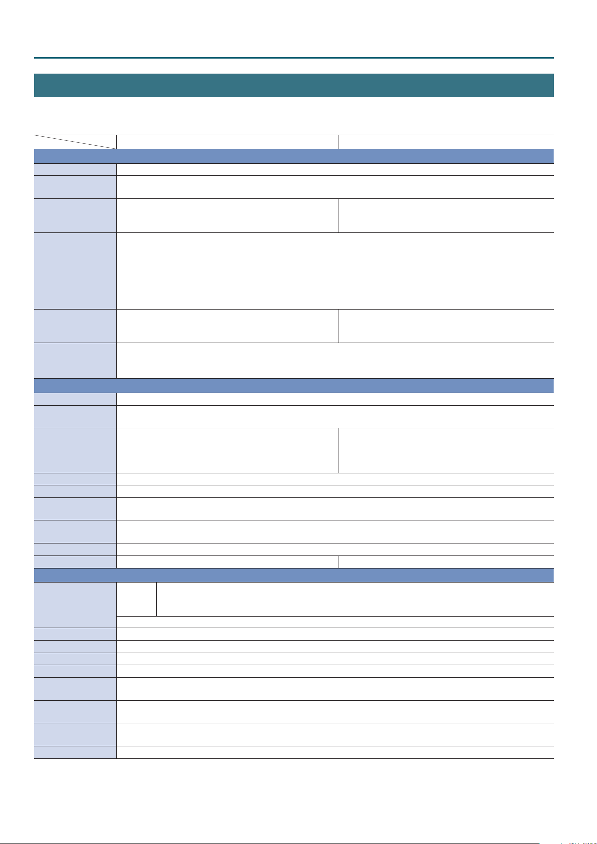
Appendices
Main Specications
Roland XS-42H: Matrix Switcher
Roland VP-42H: Video Processor
XS-42H VP-42H
9 Video
Processing 4:4:4 (Y/Pb/Pr, RGB)/10 bits, 4:2:2 (Y/Pb/Pr)/10 bits
Input Connectors
Output Connectors
Formats
Eects
Still Image
9 Audio
Sample Rate 48 kHz, 24 bits
Input Connectors
Output Connectors
Input Level LINE IN: -10 dBu (Maximum: +8 dBu)
Input Impedance LINE IN: 15 k ohms
Output Level
Output Impedance
Formats HDMI: Linear PCM, 24 bits, 48 kHz, 2 ch
Processing Mixer: 4 ch x 2 (Delay: Maximum 250 ms, Audio Follow) Mixer: 4 ch (Delay: Maximum 250 ms)
9 Others
External Connectors
Functions Scene Memory: 10, Test Pattern Generator, Test Tone Generator, EDID Emulator
Power Supply AC Adaptor
Current Draw 2.1 A
Power Consumption 25 W
Operation
Temperature
Dimensions
Weight
Accessories
INPUT HDMI 1–4: HDMI type A x 4
* HDCP Supported
OUTPUT HDMI 1–2: HDMI type A x 2
* HDCP Supported
480/59.94i (*1), 576/50i (*1), 480/59.94p (*1), 576/50p (*1), 720/59.94p, 720/50p, 1080/59.94i, 1080/50i, 1080/59.94p, 1080/50p,
800 x 600/60 (*1), 1024 x 768/60 (*2), 1280 x 720/60 (*2), 1280 x 800/60 (*2), 1366 x 768/60 (*2), 1280 x 1024/60 (*2),
1400 x 1050/60 (*2), 1600 x 1200/60, 1920 x 1080/60, 1920 x 1200/60 RB
* Conforms to CEA-861-E,VESA DMT Version 1.0 Revision 11
* Frame rate is 59.94 Hz (NTSC) or 50 Hz (PAL).
(*1) Input only.
(*2) Output refresh rate is 75 Hz when frame rate is set to 50 Hz.
Transition: Mix, Cut Layer: 4
Internal Memory: 1
Maximum Size: 1920 x 1200 pixels
Format: Windows Bitmap File (.bmp), 24-bit color, uncompressed
INPUT HDMI 1–4: HDMI type A x 4
LINE IN: RCA pin type
OUTPUT HDMI 1–2: HDMI type A x 2
LINE OUT: RCA pin type
PHONES: Stereo mini type
LINE OUT: -10 dBu (Maximum : +8 dBu)
PHONES: 72 mW + 72 mW (32 ohms)
LINE OUT: 1 k ohm
PHONES : 10 ohms
REMOTE RS-232: DB-9 type (Male)
LAN: RJ45
USB: USB A type (Use for future expansion)
USB MEMORY: USB A type (Use for USB Memory)
+0 to +40 degrees Celsius
+32 to +104 degrees Fahrenheit
242 (W) x 125 (D) x 44 (H) mm
9-9/16 (W) x 4-15/16 (D) x 1-3/4 (H) inches
1.2 kg
2 lbs 11 oz
Owner’s Manual, Leaet “USING THE UNIT SAFELY,” AC adaptor, Power cord, Rubber feet (4 pcs.), Rack mount angle set
OUTPUT HDMI 1–2: HDMI type A x 2
* HDCP Supported
* 2 Output is the same image.
* Picture in Picture with Keyer x 1, Picture in Picture x 3
* Motion Scene Switch
OUTPUT HDMI 1–2: HDMI type A x 2
* 2 Output is the same audio.
LINE OUT: RCA pin type
PHONES: Stereo mini type
* 0 dBu=0.775 Vrms
* This document explains the specications of the product at the time that the document was issued. For the latest information, refer to the
Roland website.
30
Page 31
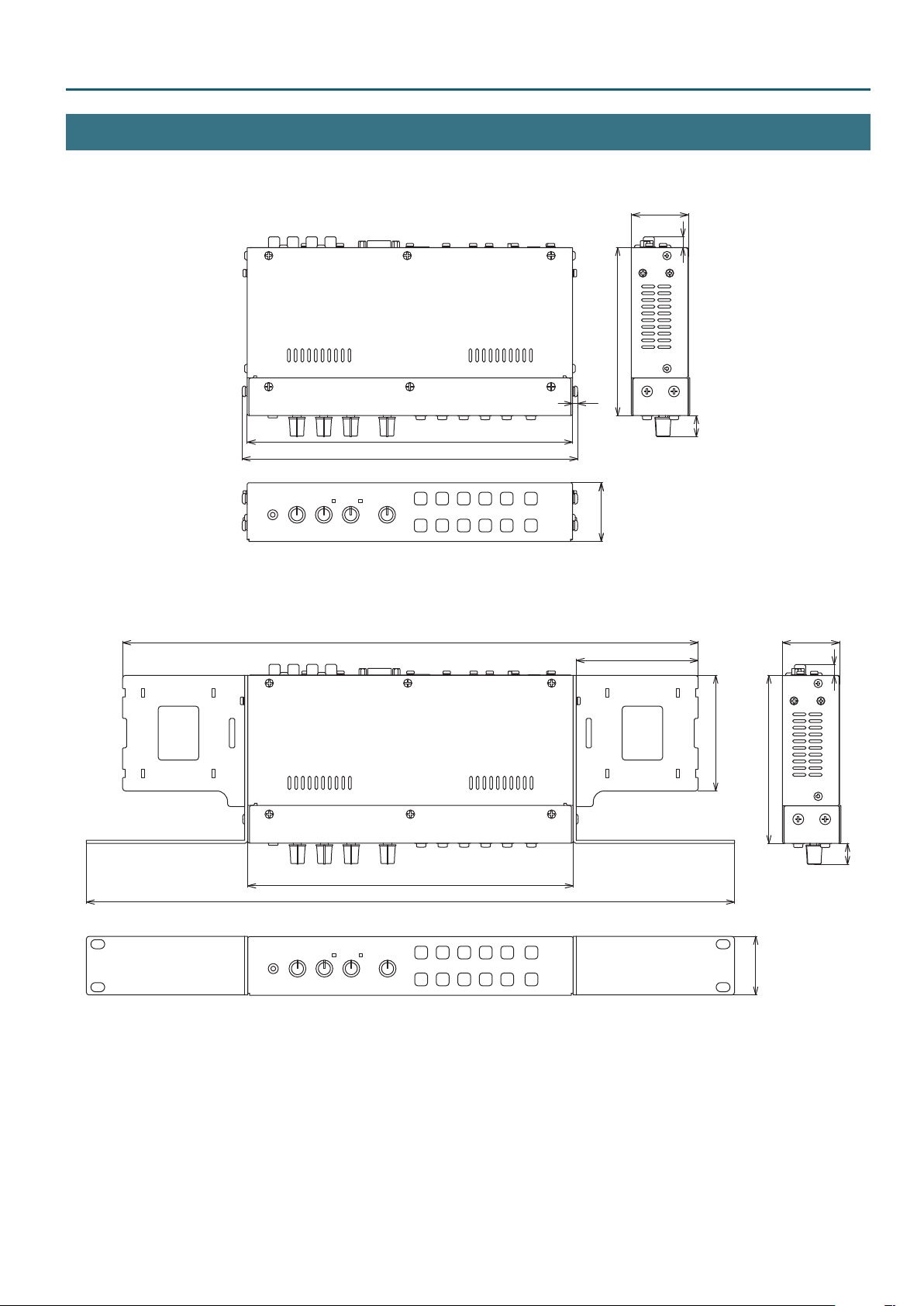
Dimensions
43
Appendices
Unit: mm
8
125
4
242
250
428
242
482
16
44
43
91
8
86
125
16
44
31
Page 32

5 Roland is an either registered trademark or trademark of Roland Corporation in the United States and/or other countries.
5 Company names and product names appearing in this document are registered trademarks or trademarks of their respective owners.
01
 Loading...