

Page 1
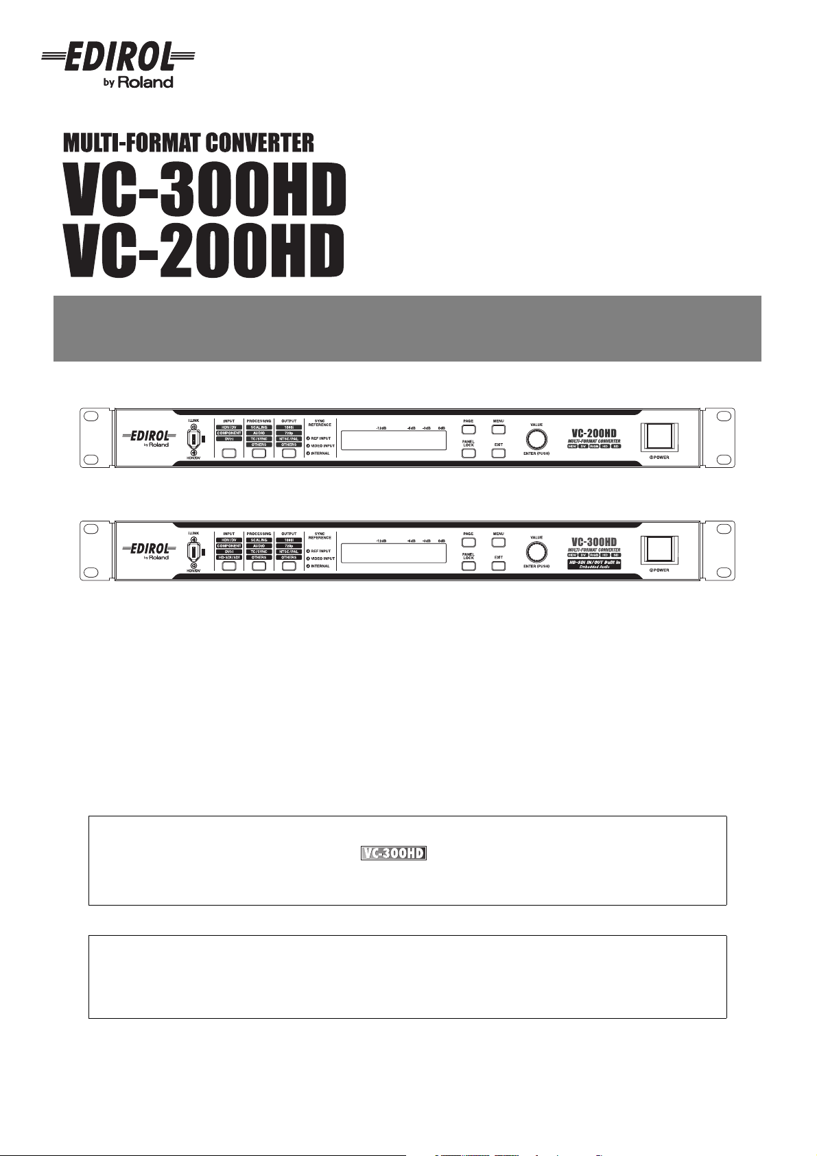
Owner’s Manual
This manual describes the VC-300HD and the VC-200HD. When reading this manual, please note the following.
• VC-300HD-specific features are marked with in the title.
• The illustrations used for this manual’s explanations depict the VC-300HD. Some of the panel inscriptions and
connectors on the VC-200HD are different.
201b
Before using this unit, carefully read the sections entitled: “IMPORTANT SAFETY INSTRUCTIONS” (p. 2), “USING
THE UNIT SAFELY” (p. 4–5), and “IMPORTANT NOTES” (p. 6). These sections provide important information
concerning the proper operation of the unit. Additionally, in order to feel assured that you have gained a good grasp
of every feature provided by your new unit, Owner’s Manual should be read in its entirety. The manual should be
saved and kept on hand as a convenient reference.
202
Copyright © 2007 ROLAND CORPORATION
All rights reserved. No part of this publication may be reproduced in any form without the written permission of ROLAND
CORPORATION.
Page 2
IMPORTANT SAFETY INSTRUCTIONS
WARNING: To reduce the risk of fire or electric shock, do not expose this apparatus to rain or moisture.
CAUTION
RISK OF ELECTRIC SHOCK
DO NOT OPEN
ATTENTION: RISQUE DE CHOC ELECTRIQUE NE PAS OUVRIR
CAUTION: TO REDUCE THE RISK OF ELECTRIC SHOCK,
DO NOT REMOVE COVER (OR BACK).
NO USER-SERVICEABLE PARTS INSIDE.
REFER SERVICING TO QUALIFIED SERVICE PERSONNEL.
The lightning flash with arrowhead symbol, within an
equilateral triangle, is intended to alert the user to the
presence of uninsulated “dangerous voltage” within the
product’s enclosure that may be of sufficient magnitude to
constitute a risk of electric shock to persons.
The exclamation point within an equilateral triangle is
intended to alert the user to the presence of important
operating and maintenance (servicing) instructions in the
literature accompanying the product.
INSTRUCTIONS PERTAINING TO A RISK OF FIRE, ELECTRIC SHOCK, OR INJURY TO PERSONS.
IMPORTANT SAFETY INSTRUCTIONS
SAVE THESE INSTRUCTIONS
WARNING - When using electric products, basic precautions should always be followed, including the following:
1. Read these instructions.
2. Keep these instructions.
3. Heed all warnings.
4. Follow all instructions.
5. Do not use this apparatus near water.
6. Clean only with a dry cloth.
7. Do not block any of the ventilation openings. Install in
accordance with the manufacturers instructions.
8. Do not install near any heat sources such as radiators,
heat registers, stoves, or other apparatus (including
amplifiers) that produce heat.
9. Do not defeat the safety purpose of the polarized or
grounding-type plug. A polarized plug has two blades with
one wider than the other. A grounding type plug has two
blades and a third grounding prong. The wide blade or the
third prong are provided for your safety. If the provided plug
does not fit into your outlet, consult an electrician for
replacement of the obsolete outlet.
10. Protect the power cord from being walked on or pinched
particularly at plugs, convenience receptacles, and the
point where they exit from the apparatus.
11. Only use attachments/accessories specified
by the manufacturer.
12. Unplug this apparatus during lightning storms or when
unused for long periods of time.
13. Refer all servicing to qualified service personnel. Servicing
is required when the apparatus has been damaged in any
way, such as power-supply cord or plug is damaged, liquid
has been spilled or objects have fallen into the apparatus,
the apparatus has been exposed to rain or moisture, does
not operate normally, or has been dropped.
For the U.K.
WARNING:
IMPORTANT:
As the colours of the wires in the mains lead of this apparatus may not correspond with the coloured markings identifying
the terminals in your plug, proceed as follows:
The wire which is coloured GREEN-AND-YELLOW must be connected to the terminal in the plug which is marked by the
letter E or by the safety earth symbol or coloured GREEN or GREEN-AND-YELLOW.
The wire which is coloured BLUE must be connected to the terminal which is marked with the letter N or coloured BLACK.
The wire which is coloured BROWN must be connected to the terminal which is marked with the letter L or coloured RED.
THIS APPARATUS MUST BE EARTHED
THE WIRES IN THIS MAINS LEAD ARE COLOURED IN ACCORDANCE WITH THE FOLLOWING CODE.
GREEN-AND-YELLOW: EARTH, BLUE: NEUTRAL, BROWN: LIVE
For the USA
DECLARATION OF CONFORMITY
Compliance Information Statement
Model Name :
Type of Equipment :
Responsible Party :
Address :
Telephone :
VC-300HD / VC-200HD
Multi-Format Converter
Roland Systems Group U.S.
425 Sequoia Drive Suite 114, Bellingham, Washington, 98226 USA
TEL: 360-594-4282
2
Page 3

Table of Contents
Setting internal processing.............................................28
Showing the Display.......................................................29
Status Screen ............................................................29
Menu Display and Operation .....................................30
Adjusting the Display .................................................30
USING THE UNIT SAFELY .......................................4
IMPORTANT NOTES ................................................6
Features ....................................................................7
Checking the Included Items ..................................8
Basic Operation................................. 9
Panel Descriptions.................................................10
Front Panel .................................................................... 10
Side Panel .....................................................................11
Rear Panel.....................................................................12
Connecting .............................................................14
Converting HD Component to HDV .......................... 15
Converting HD-SDI to HDV ......................................17
Converting computer screens (DVI or VGA) to HDV. 19
Converting HDV to HD Component .......................... 21
Converting HDV to HD-SDI ......................................23
Installation...................................................................... 25
Basic Operations....................................................26
Turning Power On/Off....................................................26
Turning power on ......................................................26
Turning power off ......................................................26
Selecting the video input connector...............................26
Selecting the audio input connector............................... 27
Selecting the video output format .................................. 27
Test Pattern / Test Tone Output .................................... 28
Appendices ......................................31
Menus and settings............................................... 32
Input / Output Signal............................................. 38
HDV ...........................................................................38
SDI.............................................................................38
DV..............................................................................38
DVI.............................................................................38
Interlaced and Progressive ........................................38
Installation and Maintenance ............................... 39
Installing and Removing the Rack Mount Fittings ..........39
Daily Maintenance .....................................................39
Fan.............................................................................39
Troubleshooting.................................................... 40
Video..........................................................................40
Audio..........................................................................40
Miscellaneous ............................................................40
Main Specifications............................................... 41
Exterior Dimensions Diagram ........................................42
VC-200HD Block Diagram .............................................43
VC-300HD Block Diagram .............................................44
Output Format Support Chart.........................................45
Index....................................................................... 46
3
Page 4
•
•
•
•
•
•
•
•
•
•
•
•
USING THE UNIT SAFELY
Used for instructions intended to alert
the user to the risk of death or severe
injury should the unit be used
improperly.
Used for instructions intended to alert
the user to the risk of injury or material
damage should the unit be used
improperly.
* Material damage refers to damage or
other adverse effects caused with
respect to the home and all its
furnishings, as well to domestic
animals or pets.
001
Before using this unit, make sure to read the
instructions below, and the Owner’s Manual.
..........................................................................................................
001-50
Connect mains plug of this model to a mains
socket outlet with a protective earthing connection.
..........................................................................................................
002a
Do not open or perform any internal modifications
on the unit.
..........................................................................................................
003
Do not attempt to repair the unit, or replace parts
within it (except when this manual provides specific
instructions directing you to do so). Refer all
servicing to your retailer, the nearest Roland
Service Center, or an authorized Roland
distributor, as listed on the “Information” page.
..........................................................................................................
004
Never use or store the unit in places that are:
Subject to temperature extremes (e.g., direct
sunlight in an enclosed vehicle, near a heating
duct, on top of heat-generating equipment); or
are
•
Damp (e.g., baths, washrooms, on wet floors);
or are
•
Humid; or are
•
Exposed to rain; or are
•
Dusty; or are
•
Subject to high levels of vibration.
..........................................................................................................
The symbol alerts the user to important instructions
or warnings.The specific meaning of the symbol is
determined by the design contained within the triangle.
In the case of the symbol at left, it is used for general
The symbol alerts the user to items that must never
be carried out (are forbidden). The specific thing that
must not be done is indicated by the design contained
within the circle. In the case of the symbol at left, it
means that the unit must never be disassembled.
The ● symbol alerts the user to things that must be
carried out. The specific thing that must be done is
indicated by the design contained within the circle. In
the case of the symbol at left, it means that the powercord plug must be unplugged from the outlet.
007
Make sure you always have the unit placed so it is
level and sure to remain stable. Never place it on
stands that could wobble, or on inclined surfaces.
..........................................................................................................
008a
The unit should be connected to a power supply
only of the type described in the operating instructions, or as marked on the top of unit.
..........................................................................................................
008e
Use only the attached power-supply cord. Also, the
supplied power cord must not be used with any
other device.
..........................................................................................................
009
Do not excessively twist or bend the power cord,
nor place heavy objects on it. Doing so can
damage the cord, producing severed elements and
short circuits. Damaged cords are fire and shock hazards!
..........................................................................................................
010
This unit, either alone or in combination with an
amplifier and headphones or speakers, may be
capable of producing sound levels that could
cause permanent hearing loss. Do not operate for
a long period of time at a high volume level, or at a
level that is uncomfortable. If you experience any
hearing loss or ringing in the ears, you should
immediately stop using the unit, and consult an
audiologist.
..........................................................................................................
011
Do not allow any objects (e.g., flammable material,
coins, pins); or liquids of any kind (water, soft
drinks, etc.) to penetrate the unit.
..........................................................................................................
4
Page 5
•
•
•
•
•
•
•
•
•
•
•
•
•
•
•
•
USING THE UNIT SAFELY
012a
Immediately turn the power off, remove the power
cord from the outlet, and request servicing by your
retailer, the nearest Roland Service Center, or an
authorized Roland distributor, as listed on the
“Information” page when:
•
The power-supply cord, or the plug has been
damaged; or
•
If smoke or unusual odor occurs
•
Objects have fallen into, or liquid has been
spilled onto the unit; or
•
The unit has been exposed to rain (or otherwise
has become wet); or
•
The unit does not appear to operate normally or
exhibits a marked change in performance.
..........................................................................................................
013
In households with small children, an adult should
provide supervision until the child is capable of
following all the rules essential for the safe
operation of the unit.
..........................................................................................................
014
Protect the unit from strong impact.
(Do not drop it!)
..........................................................................................................
015
Do not force the unit’s power-supply cord to share
an outlet with an unreasonable number of other
devices. Be especially careful when using
extension cords—the total power used by all
devices you have connected to the extension
cord’s outlet must never exceed the power rating
(watts/amperes) for the extension cord. Excessive
loads can cause the insulation on the cord to heat
up and eventually melt through.
..........................................................................................................
016
Before using the unit in a foreign country, consult
with your retailer, the nearest Roland Service
Center, or an authorized Roland distributor, as
listed on the “Information” page.
..........................................................................................................
026
Do not put anything that contains water (e.g.,
flower vases) on this unit. Also, avoid the use of
insecticides, perfumes, alcohol, nail polish, spray
cans, etc., near the unit. Swiftly wipe away any
liquid that spills on the unit using a dry, soft cloth.
..........................................................................................................
101a
The unit should be located so that its location or
position does not interfere with its proper ventilation.
..........................................................................................................
102b
Always grasp only the plug on the power-supply
cord when plugging into, or unplugging from, an
outlet or this unit.
..........................................................................................................
103a
At regular intervals, you should unplug the power
plug and clean it by using a dry cloth to wipe all
dust and other accumulations away from its
prongs. Also, disconnect the power plug from the
power outlet whenever the unit is to remain unused
for an extended period of time. Any accumulation
of dust between the power plug and the power
outlet can result in poor insulation and lead to fire.
..........................................................................................................
104
Try to prevent cords and cables from becoming
entangled. Also, all cords and cables should be
placed so they are out of the reach of children.
..........................................................................................................
106
Never climb on top of, nor place heavy objects on
the unit.
..........................................................................................................
107b
Never handle the power cord or its plugs with wet
hands when plugging into, or unplugging from, an
outlet or this unit.
..........................................................................................................
108a
Before moving the unit, disconnect the power plug
from the outlet, and pull out all cords from external
devices.
..........................................................................................................
109a
Before cleaning the unit, turn off the power and
unplug the power cord from the outlet p. 26
..........................................................................................................
110a
Whenever you suspect the possibility of lightning in
your area, pull the plug on the power cord out of
the outlet.
..........................................................................................................
118a
Should you remove screws and rubber feet, keep
them in a safe place out of children’s reach, so
there is no chance of them being swallowed
accidentally.
..........................................................................................................
5
Page 6

•
•
•
•
•
•
•
•
•
•
•
•
•
•
•
•
IMPORTANT NOTES
291b
In addition to the items listed under “IMPORTANT SAFETY INSTRUCTIONS” and “USING THE UNIT SAFELY” on pages 2
and 4–5, please read and observe the following:
•
•
Power Supply
301
Do not connect this unit to same electrical outlet that is
being used by an electrical appliance that is controlled by
an inverter (such as a refrigerator, washing machine,
microwave oven, or air conditioner), or that contains a
motor. Depending on the way in which the electrical
appliance is used, power supply noise may cause this unit
to malfunction or may produce audible noise. If it is not
practical to use a separate electrical outlet, connect a
power supply noise filter between this unit and the
electrical outlet.
307
Before connecting this unit to other devices, turn off the
power to all units. This will help prevent malfunctions and/
or damage to speakers or other devices.
308
Although the LCD and LEDs are switched off when the
POWER switch is switched off, this does not mean that the
unit has been completely disconnected from the source of
power. If you need to turn off the power completely, first
turn off the POWER switch, then unplug the power cord
from the power outlet. For this reason, the outlet into which
you choose to connect the power cord’s plug should be
one that is within easy reach and readily accessible.
Placement
351
Using the unit near power amplifiers (or other equipment
containing large power transformers) may induce hum. To
alleviate the problem, change the orientation of this unit; or
move it farther away from the source of interference.
352a
This device may interfere with radio and television
reception. Do not use this device in the vicinity of such
receivers.
352b
Noise may be produced if wireless communications
devices, such as cell phones, are operated in the vicinity of
this unit. Such noise could occur when receiving or initiating a call, or while conversing. Should you experience
such problems, you should relocate such wireless devices
so they are at a greater distance from this unit, or switch
them off.
355b
When moved from one location to another where the
temperature and/or humidity is very different, water
droplets (condensation) may form inside the unit. Damage
or malfunction may result if you attempt to use the unit in
this condition. Therefore, before using the unit, you must
allow it to stand for several hours, until the condensation
has completely evaporated.
360
Depending on the material and temperature of the surface
on which you place the unit, its rubber feet may discolor or
mar the surface.
You can place a piece of felt or cloth under the rubber feet
to prevent this from happening. If you do so, please make
sure that the unit will not slip or move accidentally.
Maintenance
401a
For everyday cleaning wipe the unit with a soft, dry cloth or
one that has been slightly dampened with water. To
remove stubborn dirt, use a cloth impregnated with a mild,
non-abrasive detergent. Afterwards, be sure to wipe the
unit thoroughly with a soft, dry cloth.
402
Never use benzine, thinners, alcohol or solvents of any
kind, to avoid the possibility of discoloration and/or deformation.
Copyright
853
Do not use this unit for purposes that could infringe on a
copyright held by a third party. We assume no responsibility whatsoever with regard to any infringements of thirdparty copyrights arising through your use of this unit.
Additional Precautions
553
Use a reasonable amount of care when using the unit’s
buttons, sliders, or other controls; and when using its jacks
and connectors. Rough handling can lead to malfunctions.
554
Never strike or apply strong pressure to the display.
556
When connecting / disconnecting all cables, grasp the
connector itself—never pull on the cable. This way you will
avoid causing shorts, or damage to the cable’s internal
elements.
557
A small amount of heat will radiate from the unit during
normal operation.
558b
To avoid disturbing your neighbors, try to keep the unit’s
volume at reasonable levels (especially when it is late at
night).
559a
When you need to transport the unit, package it in the box
(including padding) that it came in, if possible. Otherwise,
you will need to use equivalent packaging materials.
562
Some connection cables contain resistors. Do not use
cables that incorporate resistors for connecting to this unit.
The use of such cables can cause the sound level to be
extremely low, or impossible to hear. For information on
cable specifications, contact the manufacturer of the cable.
220
* All product names mentioned in this document are
trademarks or registered trademarks of their
respective owners.
6
Page 7

Features
HDV/DV Conversion Feature
This converts analog component, DVI-I, or SDI (HD/SD) signals to HDV or DV in real
time. It can also go the other way and convert HDV or DV streams to analog component,
DVI, or SDI (HD/SD) signals.
* Only the VC-300HD supports SDI signals.
High-performance Scaler
The unit has a built-in scaler that can convert input video to video formats having a
different number of pixels. For example, it’s possible to convert 720p video, or RGB
video from a computer, to 1080i.
High-quality 4:4:4 10-bit Processing
The VC-200HD/VC-300HD use 4:4:4/10-bit processing for video calculations. Analog
component input is also digitized at 4:4:4 with 10-bit depth. This means that video
handled by the unit is processed at the highest quality possible, so there is no
degradation.
Simultaneous Output
Converted video is simultaneously output to each output connector.
* See p. 45 for the relationship between formats and the connectors that can provide a
particular type of output. With certain combinations, some output connectors cannot
provide output in the selected video format with some combinations.
HD-SDI Input and Output
This VC-300HD is capable of SDI (HD/SD) input and output. This lets you input video
digitally from commercial-use video equipment using a single BNC cable.
Component Input and Output
You can input and output HD and SD video using analog components. For instance, it’s
possible to convert output from the V-440HD Multi-format Video Mixer to HDV or HDSDI. You can then input the converted video to an HDV video deck or HD device for
recording.
DVI-I Input
RGB video from a computer can be input, so you can record presentations and the like
on HDV or other video formats. Because DVI-I is supported, you can use either analog
or digital signals.
Reference-signal Input and Output
The unit’s external synchronizing-signal input is compatible with black burst as well as
2-level and 3-level synchronization. This lets you synchronize the unit to existing house
sync.
Audio Input and Output with Audio Delay
You can input analog audio and embed it in HDV or SDI video. What’s more, you can
set an audio delay, enabling you to delay the audio so it matches a video signal that’s
been delayed as the result of being routed through a switcher (or for some other
reason). You can even make delay settings for audio data input from HDV or SDI.
7
Page 8
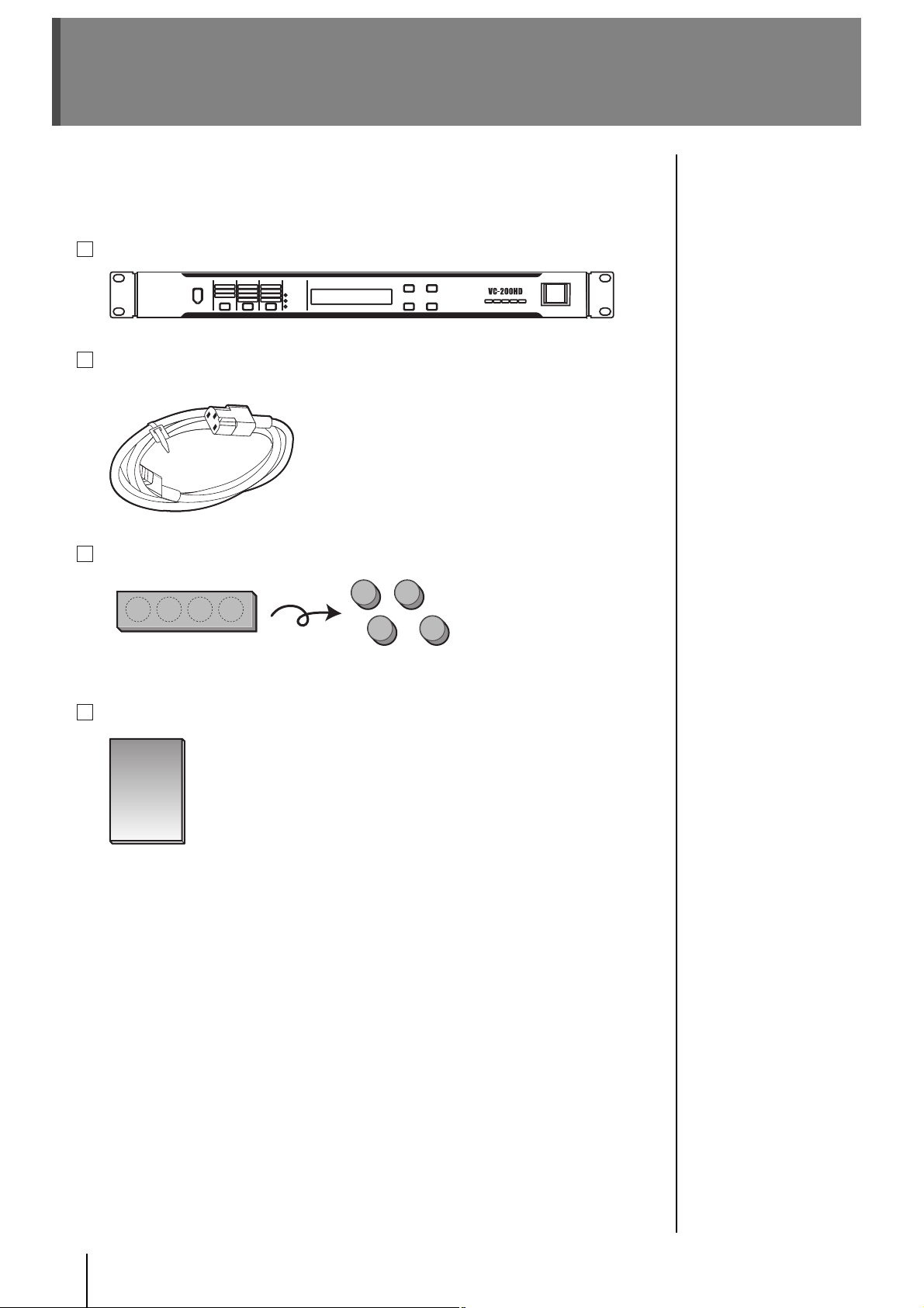
Checking the Included Items
The VC-300HD/VC-200HD is packaged with the following items. Please check that all of the items are
included.
* If you find that any item is missing, contact the nearest authorized EDIROL/Roland distributor in your
country.
VC-300HD / VC-200HD
Power Cord
* Use only the attached power-supply cord.
Rubber Feet (4)
* The rubber feet are arranged onto one pad. Please remove from the pad to use them.
Owner’s Manual
8
Page 9

Basic Operation
9
Page 10
Panel Descriptions
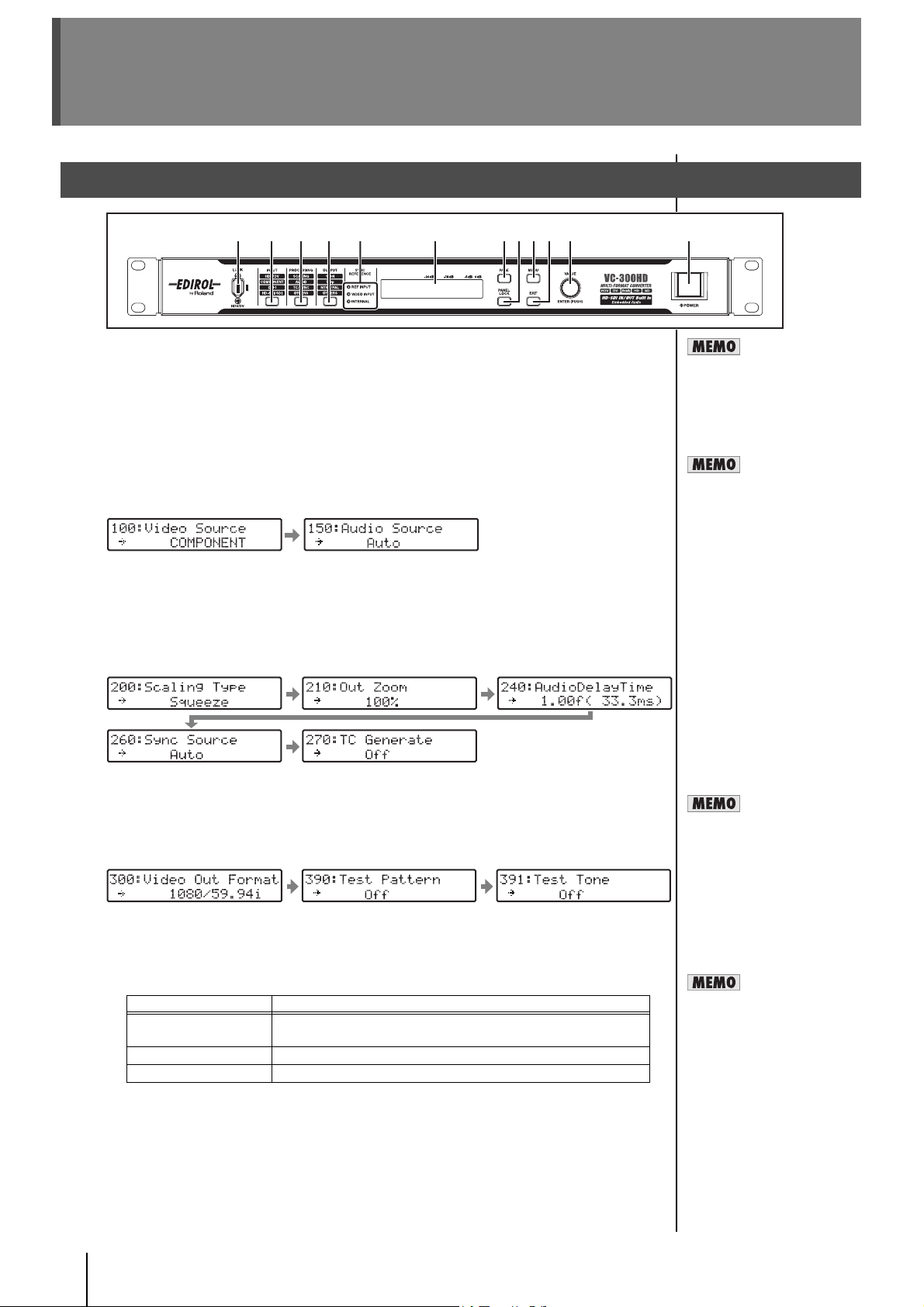
Front Panel
1 2 3 4 5 6 7 8 9 10 11 12
1 i.LINK Connector (Front Panel)
This connector handles the input/output of HDV/DV signals and allows for connection of HDV/DV
video equipment.
* Please do not use this together with the i.LINK connector (p. 13) on the rear panel of the unit. If they
are used together, the connected video equipment may not operate properly.
2 INPUT Button
Displays the menu for selecting the input connectors for audio and video (p. 26 and p. 27).
The menu screen changes each time the INPUT button is pressed. The values of settings are
changed with the VALUE/ENTER knob.
Menu displayed when the INPUT button is pressed
* When a connector with no input is selected, a black matte image is output.
3 PROCESSING Button
Displays the menu for setting internal processing for audio and video (p. 28). The menu screen
changes each time the PROCESSING button is pressed. The values of settings are changed with
the VALUE/ENTER knob.
Menu displayed when the PROCESSING button is pressed
See "Input Format Table" and
"Output Format Table" (p. 13)
for the signal formats that can
be input to, or output from the
i.LINK connector.
The i.LINK connector on this
device is a dedicated HDV/DV
signal connector. The following
devices cannot be connected
because the signal is not
compatible.
• i.LINK connectors of MicroMV
format digital video cameras
(MicroMV signal)
• i.LINK connectors on D-VHS
decks (MPEG-TS signal)
4 OUTPUT Button
Displays the screen for selecting the video output format and test pattern (p. 27 and p. 28).
The menu screen changes each time the OUTPUT button is pressed. The values of settings are
changed with the VALUE/ENTER knob.
Menu displayed when the OUTPUT button is pressed
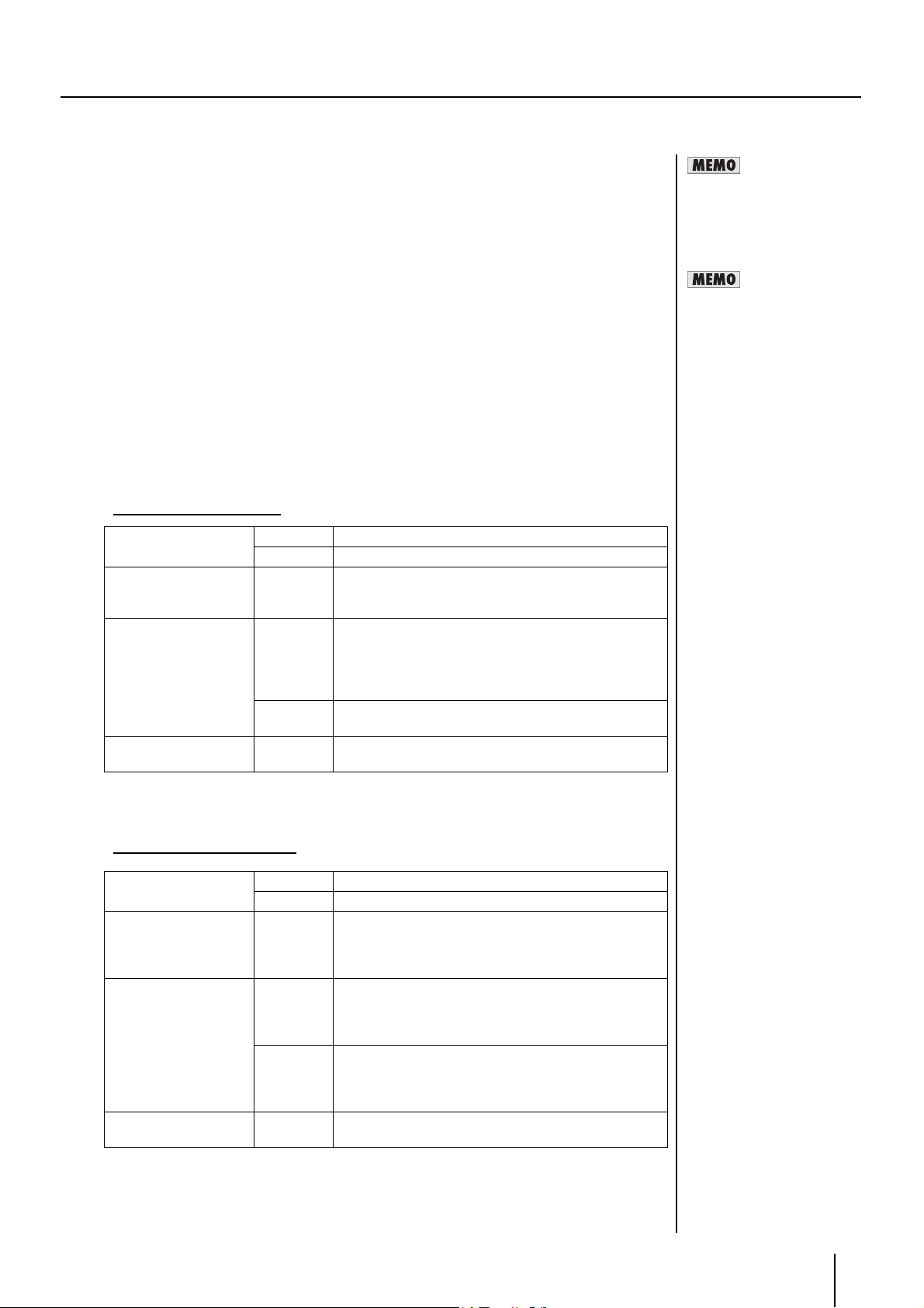
5 SYNC REFERENCE Indicators
These display the synchronizing signal that has been selected.
Indicator Selected synchronizing signal
REF INPUT Uses an external synchronizing signal input via the REF INPUT
connector (p. 13).
VIDEO INPUT Uses the synchronizing signal in the incoming video signal.
INTERNAL Uses the synchronizing signal in the incoming video signal.
* The synchronizing signal can be set with "260: Sync Source," which can be accessed by pressing
the PROCESSING button a number of times. See "Setting internal processing" (p. 28) for details.
* The synchronizing signal can also be set with "260: Sync Source" (p. 34) from the Menu (p. 30).
No picture is output from a
connector that isn’t compatible
with the selected output
format.
The indicator blinks in the
following situations.
• The selected synchronizing
signal is not being input
• A synchronizing signal that is
different from the output
format (p. 27) is being input
• The synchronizing signal
cannot be locked
10
Page 11
6 Display
Shows the Status screens (four types) indicating the status of the unit. Pressing the PAGE button
cycles you through the Status screens. The Menu screen is displayed by pressing MENU button.
While the Menu screen is displayed, the MENU button is lit.
7 PAGE Button
Pressed to select what is shown in the display, such as the Status screen or Menu screen.
8 PANEL LOCK Button
Locks front panel operations. To release panel lock, press and hold down the PANEL LOCK button
for at least two seconds.
9 MENU Button
Shows the menu on the display. If the MENU button is pressed while the Menu is displayed, the unit
exits from the Menu screen and returns to the Status screen. Various settings are made with the
menu. See "Menu Display and Operation" (p. 30) for details.
10 EXIT Button
Cancels the content shown in the menu. If the EXIT button is pressed while an item number (p. 30)
is blinking, the unit exits from the Menu screen and returns to the Status screen. If the EXIT button
is pressed while a setting's value (p. 30) is blinking, the selected value is canceled.
11 VALUE/ENTER Knob
Menu items can be selected by turning the knob clockwise or counterclockwise. Press the knob to
select the value for a setting that is displayed onscreen with menu operations.
Panel Descriptions
12 Power Button
Switches the unit’s power on and off.
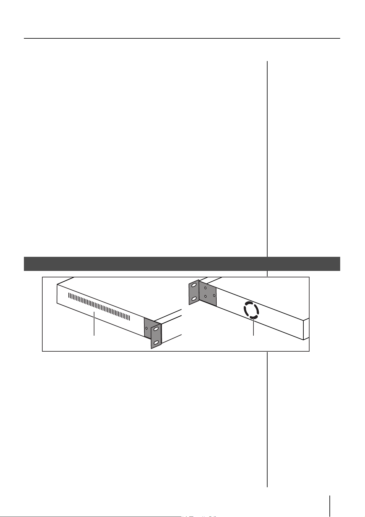
Side Panel
(Top Panel)
1 Cooling fan intake vent
2 Cooling fan exhaust vent
The internal cooling fan regulates temperature increases inside the unit. The internal heat is
expelled from this side.
* Please do not block the cooling fan intake vent or exhaust vent. If the exhaust or intake vent is
blocked, the internal temperature will rise and heat damage may occur.
(Top Panel)
21
11
Page 12
Panel Descriptions
AUDIO OUTPUT CH1, CH2
AUDIO INPUT CH1, CH2
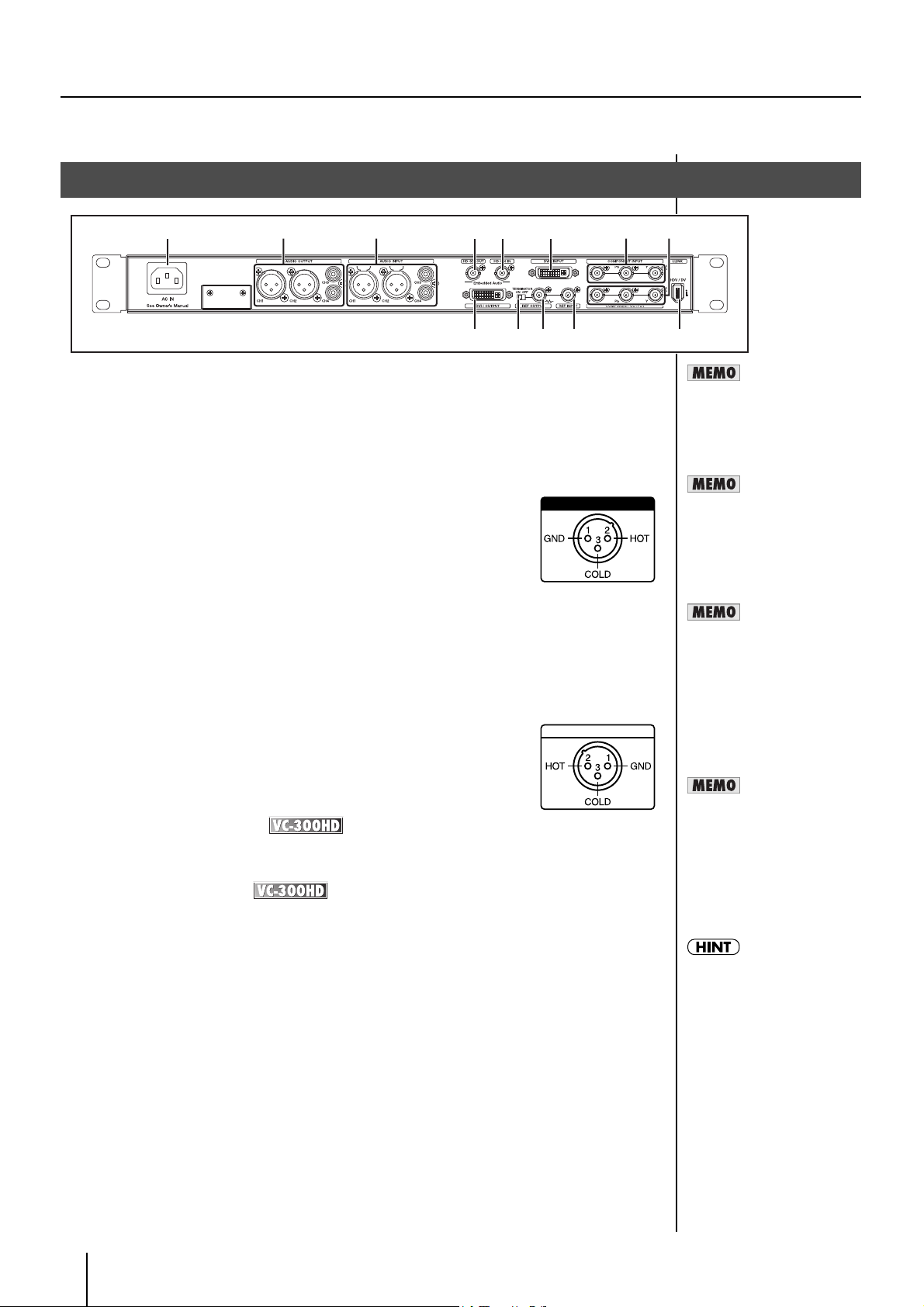
Rear Panel
922
1 64 5
2 73 8
109 11 12 13
1 AC Inlet
Accepts connection of the supplied power cord.
2 AUDIO OUTPUT Connectors
CH1 and CH2 Connectors (XLR Type/Balanced Type)
CH3 and CH4 Connectors (RCA Phono Type, Unbalanced
Input)
These connectors provide output of analog audio. Here is where you connect
equipment such as monitoring speakers or a television, or a video deck if you
intend to record the output.
* This device is equipped with balanced (XLR) type jacks. Wiring diagrams for
these jacks are shown to the right. Make connections after first checking the
wiring diagrams of other equipment you intend to connect.
3 AUDIO INPUT Connectors
CH1 and CH2 Connectors (XLR Type/Balanced Type)
CH3 and CH4 Connectors (RCA Phono Type, Unbalanced
Input)
These are connectors for inputting analog audio. Audio to be embedded in
HDV, DV, and SDI is input here.
* Audio that is included with HDV or DV is output from the AUDIO OUTPUT
connectors CH1/CH2 or CH3/CH4.
* This instrument is equipped with balanced (XLR) type jacks. Wiring diagrams
for these jacks are shown to the right. Make connections after first checking
the wiring diagrams of other equipment you intend to connect.
4 HD-SDI OUT Connector
This connector outputs SDI. Switching of HD-SDI/SD-SDI output takes place automatically when
the procedure in "Selecting the video output format" (p. 27) is used to change the output format.
See the tables to the right for
the signal formats that can be
input or output to each
connector.
You can apply delay to output
audio. For more information,
refer to 240: "AudioDelay
Time" (p. 34).
926a
When connection cables with
resistors are used, the volume
level of equipment connected
to the inputs (AUDIO INPUT,
AUDIO OUTPUT) may be low.
If this happens, use connection
cables that do not contain
resistors.
See p. 13 for the signal
formats that can be input to, or
output from the HD-SDI INPUT
and HD-SDI OUT connectors.
5 HD-SDI IN Connector
This connector receives SDI input. The input SDI is automatically identified as either HD-SDI or SDSDI.
6 DVI-I INPUT Connector
This connector receives DVI-I signal input. Video that is output from a PC or other DVI output device
is input here. The input video format is automatically identified.
7 COMPONENT INPUT Connectors
This connector receives component (Y, Pb, Pr) input. HD component video signals from HD devices
such as the EDIROL V-440HD and SD component video signals from devices such as DVDs are
input here. The HD signals and SD signals are automatically identified.
8 COMPONENT OUTPUT Connectors
These connectors are for outputting component video signals. They are for connecting equipment
such as a monitor television, video mixer, etc.
9 DVI-I OUT Connector
This connector is for outputting a DVI-I signal. This is typically for connecting a flat-screen monitor
or television monitor capable of receiving DVI-I signals.
12
DVI-I
DVI-I receives analog and
digital video signals. VGA (D-
sub 15-pin) is connected via a
commercially available DVI-
VGA conversion adapter. This
manual uses DVI-A to denote
analog video signals input from
DVI-I and DVI-D to denote
digital video signals.
* See "DVI" (p. 38) for details.
Page 13
10 TERMINATOR Switch
Switch this on when you don’t want to loop-through the synchronizing signal from the REF OUTPUT
connector.
11 REF OUTPUT Connector
This is the loop through output connector for external synchronizing signals input via the REF
INPUT connector. It is connected to the external synchronizing signal input connector of the video
equipment to which the unit is synchronized. When using this connector, turn the TERMINATOR
switch off.
12 REF INPUT Connector
This connector is for inputting the synchronizing signal when operating the unit with external
synchronization. Connect a sync-signal generator or the like here.
13 i.LINK Connector (Rear Panel)
This connector is for HDV/DV signal input and output. You can connect HDV/DV video equipment
here.
* Please do not use this together with the i.LINK connector (p. 8) on the front panel of the unit. If they
are used together, the connected video equipment may not operate properly.
The specifications and appearance of this product are subject to change without notice.
Input Format Table
Panel Descriptions
See the tables to the right for
the signal formats that can be
input or output to each
connector.
The actual name of the
“external synchronizing-signal
input connector” may vary from
one video device to another.
i.LINK Connector HDV 1080/59.94i, 1080/50i, 720/59.94p, 720/50p
DV 480/59.94i (NTSC), 576/50i (PAL)
COMPONENT INPUT
Connectors
DVI-I INPUT Connector Digital
HD-SDI IN Connector Digital 1080/59.94i, 1080/50i, 720/59.94p, 720/50p,
* If video in a format not listed above is input, it will not be displayed correctly.
Y/Pb/Pr 1080/59.94i, 1080/50i, 720/59.94p, 720/50p,
480/59.94p, 576/50p,
480/59.94i (NTSC), 576/50i (PAL)
1600x1200/60Hz, 1400x1050/60/75Hz,
(RGB)
Analog
(Y/Pb/Pr)
1366x768/60, 1280x1024/60/75Hz,
1280x768/60/75Hz, 1280x960/60Hz,
1152x864/75Hz, 1024x768/60/75Hz,
800x600/60/75Hz, 640x480/60/75Hz
1024x768/60Hz, 800x600/60/75Hz,
640x480/60/75Hz
480/59.94i (NTSC), 576/50i (PAL)
Output Format Table
i.LINK Connector HDV 1080/59.94i, 1080/50i, 720/59.94p, 720/50p
DV 480/59.94i (NTSC), 576/50i (PAL)
COMPONENT OUTPUT
Connectors
DVI-I OUT Connector Digital
HD-SDI OUT Connector Digital 1080/59.94i, 1080/50i, 720/59.94p, 720/50p,
Y/Pb/Pr 1080/59.94p, 1080/50p, 1080/59.94i,
1080/50i, 720/59.94p, 720/50p,
480/59.94p, 576/50p,
480/59.94i (NTSC), 576/50i (PAL)
1080/59.94p, 1080/50p, 1080/59.94i,
(RGB)
Analog
(Y/Pb/Pr)
1080/50i, 720/59.94p, 720/50p,
480/59.94p, 576/50p,
480/59.94i (NTSC), 576/50i (PAL)
1080/59.94p, 1080/50p, 1080/59.94i,
1080/50i, 720/59.94p, 720/50p,
480/59.94p, 576/50p,
480/59.94i (NTSC), 576/50i (PAL)
480/59.94i (NTSC), 576/50i (PAL)
13
Page 14
Connecting
Connect the VC-200HD or VC-300HD in the way that is appropriate for the intended purpose.
This section describes how the various connections need to be made, according to purpose.
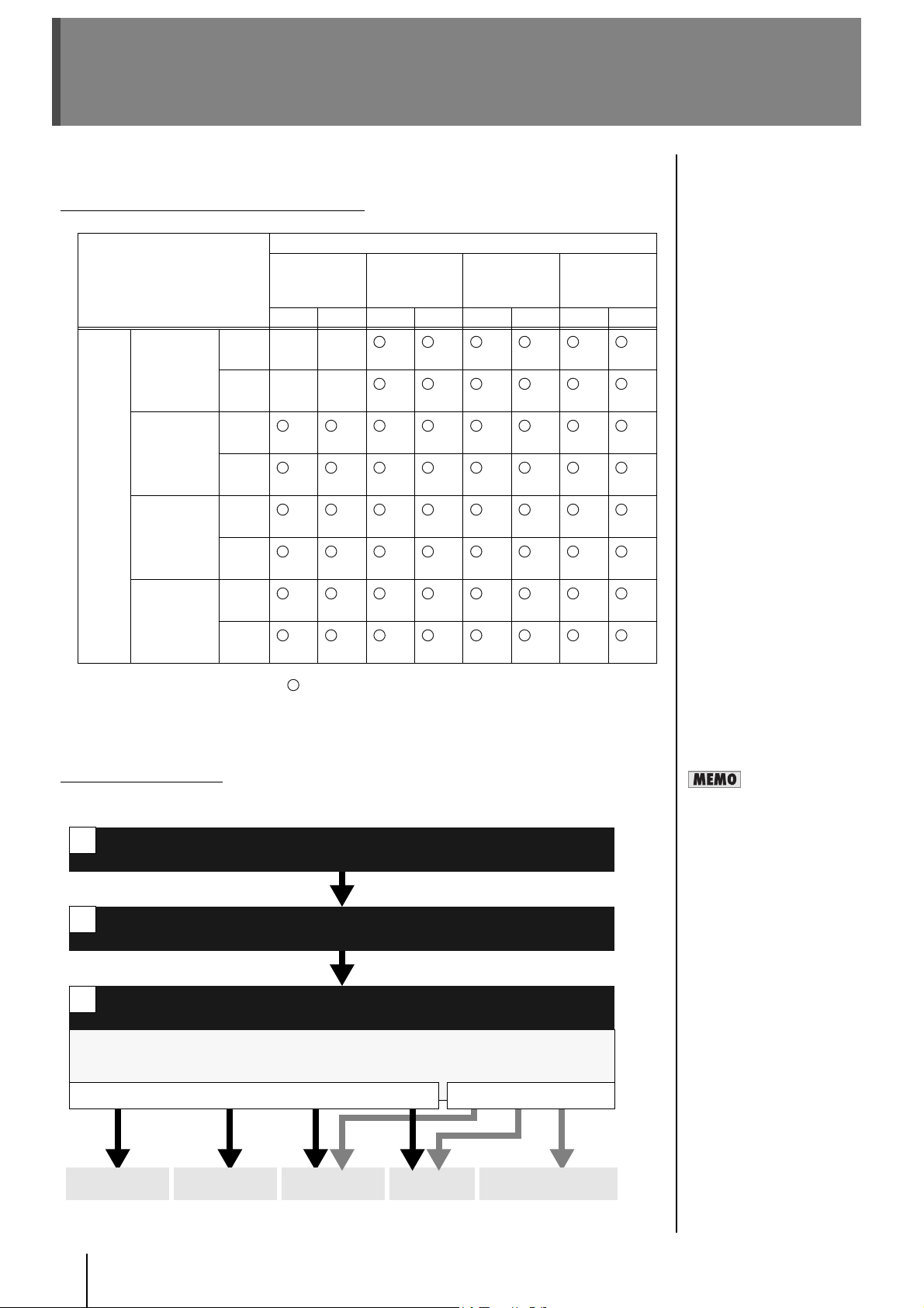
Connection Overview and Support Pages
Input
Output i.LINK
Connector
COMPONEN
T OUTPUT
Connector
DVI-I
Connector
HD-SDI OUT
Connector
i.LINK
Connector
HDV DV HD SD Digital Analog HD SD
HDV — —
DV — —
HD
p. 21 p. 22 p. 16 p. 16 p. 20 p. 20 p. 18 p. 18
SD
p. 22 p. 22 p. 16 p. 16 p. 20 p. 20 p. 18 p. 18
Digital
p. 24 p. 24 p. 16 p. 16 p. 20 p. 20 p. 18 p. 18
Analog
p. 24 p. 24 p. 16 p. 16 p. 20 p. 20 p. 18 p. 18
HD
p. 23 p. 24 p. 16 p. 16 p. 20 p. 20 p. 18 p. 18
SD
p. 24 p. 24 p. 16 p. 16 p. 20 p. 20 p. 18 p. 18
COMPONENT
INPUT
Connector
p. 15 p. 16 p. 19 p. 19 p. 17 p. 17
p. 16 p. 16 p. 20 p. 20 p. 18 p. 18
DVI-I
Connector
HD-SDI IN
Connector
* The combinations indicated with in the chart are input/output that can be converted.
* The input/output combinations are described on the pages indicated in the chart with p. ??.
* Wherever “VC-300HD” appears, it means that it is supported only on the VC-300HD.
* Wherever “—” is shown, it means that it is not supported on either the VC-200HD or VC-300HD.
About the Procedures
In general, the operating procedures introduced in p. 15–25 involve proceeding through the steps
below.
1
2
3
Output of the audio/video in the selected format begins from the appropriate output connectors.
Process for up-conversion, down-conversion, and frame rate conversion are automatically set with
Select the input connectors (video/audio)
See “Selecting the video input connector” (p. 26), “Selecting the audio input connector” (p. 27).
Select the output format (video only)
Connect the devices
See “Rear Panel” (p. 12).
See “Selecting the video output format” (p. 27).
the settings for step 2 and step 3.
Video Output Audio Output
Frame Rate
This index indicates the
number of times (number of
frames) that a screen can be
redrawn per second.
For example, a value of 1080/
59.94i means that the screen
is redrawn 59.94 times per
second.
COMPONENT
OUTPUT
14
DVI-I
OUTPUT
i.LINK
OUTPUT
HD-SDI
OUT
AUDIO OUTPUT
CH1/2, CH3/4
Page 15
Converting HD Component to HDV
HD component video can be converted to HDV, and the HD video can be recorded onto HDV tape.
When recording HD component output from an HD video switcher, inexpensive HDV tape can be used.
Connecting
HD video device
HDV device
Connection and Configuration
1 Connect the HD video device to the COMPONENT INPUT connector using a BNC
cable.
* Make sure to connect the BNC cable securely. If the connection is bad, the color of the output video
may be off or synchronization may be lost.
2 Connect the HDV device to the i.LINK connector using an i.LINK (IEEE1394) cable.
COMPONENT INPUT iLink
BNC x3 IEEE1394
VC-200HD / VC-300HD
HD video device
HDV device
3 Connect the HD video device (or audio device) to the AUDIO INPUT connectors with
an audio cable.
4 Press the POWER switch to start the unit.
After the unit starts, turn on power to the HD video device and the HDV device.
5 Select the video input connector.
5-1. Press the INPUT button until "100: Video Source" is shown in the display.
5-2. Use the VALUE/ENTER knob to select "COMPONENT."
5-3. Press the VALUE/ENTER knob to confirm the selection.
When the output from the
i.LINK connector on this unit is
not recognized by the HDV
device, turn off power to this
unit and then restart it.
At the factory default settings,
audio input to the Ch1 and Ch2
AUDIO INPUT connectors is
converted to HDV audio.
If you want to use audio input
to AUDIO INPUT connectors
Ch3 and Ch4, select "CH1-2:34 CH3-4:1-2" or "CH1-2:3-4
CH3-4:3-4" in the "160:AUDIO
In Ch" menu (p. 32).
To adjust the nominal input
level of audio input to the
AUDIO INPUT connectors, use
the "161: In Ch1&2 NomLv"
menu (p. 33) and the "162: In
Ch3&4 NomLv" menu.
15
Page 16

Connecting
6 Select the output format.
6-1. Press the OUTPUT button until "300: Video Out Format" is shown in the display.
6-2. Use the VALUE/ENTER knob to select "1080/59.94i," "1080/50i," "720/59.94p," or "720/50p."
6-3. Press the VALUE/ENTER knob to confirm the selection. The video signal is output in the selected
video format.
Converting HD Component to HD-SDI
Perform the settings on the previous page, and connect the HD video device with HD-SDI to
the HD-SDI OUT connector. The selection made in Step 6 determines the format of the video
that is output. Set this item according to the connected device.
* When changing the output video frame rate, please select an appropriate value in step 6.
* Refer to the user’s manual that came with your HD video equipment to find out which video
formats it supports.
If the aspect ratios of the video
selected in step 4. and the
output format selected in step
6. are different, select the
scaling type with "200: Scaling
Type" (p. 33) from the Menu
(p. 30).
Up-converting SD Component to HDV
By using the scaling feature of this device, SD component video can be up-converted to HD
size as well as converted to HDV.
Perform the settings on the previous page, and connect the SD video device to the
COMPONENT INPUT connector. The selection made in Step 6 determines the format of the
video that is output. Set this item according to the connected device.
* When changing the output video frame rate, please select an appropriate value in step 6.
* Refer to the user’s manual that came with your HD video equipment to find out which video
formats it supports.
Converting HD Component or SD Component to DV
By using the scaling feature of the VC-300HD/VC-200HD, HD component video can be downconverted to SD size as well as converted to DV. Perform the settings on the previous page,
and connect the DV device to the i.LINK connector. Select “480/59.94i” in Step 6.
* Use this same procedure to convert SD component to DV.
* When converting to PAL, select "576/50i" in step 6. For NTSC, select “480i/59.94i.”
Converting HD Component to DVI-I
Perform the settings on the previous page, and connect a DVI-I compatible device, such as a
LCD monitor, to the DVI-I OUT connector. The selection made in Step 6 determines the
format of the video that is output. Set this item according to the connected device.
* When changing the output video frame rate, please select an appropriate value in step 6.
Changing the Component Size
The VC-300HD/VC-200HD converts (cross converts) 1080i size HD component to 720p as
well as SD component to either HD component can size. In this case, select the format to be
converted in Step 6, and connect a video device that is compatible with the output format to
the COMPONENT OUT connector.
16
Page 17

Converting HD-SDI to HDV
Since the VC-300HD/VC-200HD offers HD-SDI input, the HD-SDI or SDI from an HD video device can
be converted to HDV.
The output from the HD video switcher can be recorded in HDV, or the video from an HD video deck
can be converted to HDV.
Connecting
HD video device
HDV device
Connection and Configuration
1 Connect the HD video device to the HD-SDI IN connector using a BNC cable.
* Make sure to use a 75 ohm BNC cable. The VC-300HD may not be able to acceptably receive SDI if
you use a cable that cannot transmit HD SDI.
* Make sure to connect the BNC cable securely. If the connection is bad, the color of the output video
may be off or synchronization may be lost.
2 Connect the HDV device to the i.LINK connector using an i.LINK (IEEE1394) cable.
HD-SDI IN iLink
BNC IEEE1394
HD video device
HDV device
3 Press the POWER switch to start the unit.
After the unit starts, turn on power to the HD video device and the HDV device.
4 Select the video input connector.
4-1. Press the INPUT button until "100: Video Source" is shown in the display.
4-2. Use the VALUE/ENTER knob to select "SDI."
4-3. Press the VALUE/ENTER knob to confirm the selection.
When the output from the
i.LINK connector on this unit is
not recognized by the HDV
device, turn off power to this
unit and then restart it.
5 Select the audio input connector.
When using HD-SDI that does not have embedded audio, the sound input via the AUDIO INPUT
connector must be selected.
5-1. Press the INPUT button until "150: Audio Source" is shown in the display.
5-2. Use the VALUE/ENTER knob to select "SDI."
5-3. Press the VALUE/ENTER knob to confirm the selection.
17
Page 18

Connecting
6 Select the output format.
6-1. Press the OUTPUT button until "300: Video Out Format" is shown in the display.
6-2. Use the VALUE/ENTER knob to select "1080/59.94i," "1080/50i," "720/59.94p," or "720/50p."
6-3. Press the VALUE/ENTER knob to confirm the selection. The video signal is output in the selected
video format.
Converting SD-SDI to HDV
By using the scaling feature of the VC-300HD/VC-200HD, SD-SDI component video can be
up-converted to HD size as well as converted to HDV. In this case, conversion can be
performed using the same procedure as shown on the previous page.
* If conversion cannot be performed properly, it is possible that the “140: SDI IN” (p. 32) from
the Menu (p. 30) is not set to “Auto.”
If the aspect ratios of the video
selected in step 5. and the
output format selected in step
6. are different, select the
scaling type with "200: Scaling
Type" (p. 33) from the Menu
(p. 30).
Converting HD-SDI to DV
By using the scaling feature of the VC-300HD/VC-200HD, HD-SDI can be down-converted to
SD size as well as converted to DV. In this case, after connecting using the procedure on the
previous page, select “SD” in Step 6.
* When converting to PAL, select "576/50i" in step 6. For NTSC, select “480/59.94i.”
Converting SD-SDI to DV
Perform the settings on the previous page, and connect the SD video device to the HD-SDI
IN connector. In this case, select “480/59.94i” in Step 6.
* When converting to PAL, select "576/50i" in step 6. For NTSC, select “480/59.94i.”
Converting HD-SDI (SD-SDI) to Component
Perform the settings on the previous page, and connect the HD video device to the
COMPONENT OUTPUT connector. The selection made in Step 6 determines the format of
the video that is output. Set this item according to the connected device.
* When changing the output video frame rate, please select an appropriate value in step 6.
* Refer to the user’s manual that came with your HD video equipment to find out which video
formats it supports.
* When “480/59.94i” is used in Step 6, SD component is output. When converting to PAL,
select "576/50i" in step 6. For NTSC, select “480/59.94i.”
Converting HD-SDI (SD-SDI) to DVI-I
Perform the settings on the previous page, and connect a DVI-I compatible device, such as a
LCD monitor, to the DVI-I OUTPUT connector. The selection made in Step 6 determines the
format of the video that is output. Set this item according to the connected device.
* When changing the output video frame rate, please select an appropriate value in step 6.
18
Changing HD-SDI (SD-SDI) Size
The VC-300HD/VC-200HD converts (cross converts) 1080i size HD-SDI to 720p, and SD-SDI
and HD-SDI can be mutually converted. In this case, select the format to be converted in Step
6, and connect the video device supporting the output format to the HD-SDI OUT connector.
Page 19

Converting computer screens (DVI or VGA) to HDV
DVI or VGA output from a computer can be converted to HDV, and the high resolution images can be
recorded to a video. Because the computer screen can be recorded in HD, small text and graphics do
maintain clarity.
* To input VGA output to the VC-300HD/VC-200HD, please use an RGB-DVI conversion connector
and cable to convert to the DVI connector.
* See “DVI” (p. 38) for explanation on DVI.
Connecting
At the factory default settings,
audio input to the Ch1 and Ch2
AUDIO INPUT connectors is
converted to HDV audio.
If you want to use audio input
to AUDIO INPUT connectors
Ch3 and Ch4, select "CH1-2:34 CH3-4:1-2" or "CH1-2:3-4
CH3-4:3-4" in the "160:AUDIO
In Ch" menu (p. 32).
Computer
HDV device
Connection and Configuration
1 Connect the computer to the DVI-I INPUT connector using a DVI cable.
* Please use a cable that is suitable for your computer to make the connection.
2 Connect the HDV device to the i.LINK connector using an i.LINK (IEEE1394) cable.
DVI-I INPUT iLink
DVI IEEE1394
Computer
* When the output from the i.LINK connector on this unit is not recognized by the HDV device, turn off
power to this unit, then restart it.
HDV device
3 Connect the computer (or audio device) to the AUDIO INPUT connector using a
audio cable.
4 Press the POWER switch to start the unit.
After the unit starts, turn on power to the computer device and the HDV device.
5 Select the video input connector.
5-1. Press the INPUT button until "100: Video Source" is shown in the display.
5-2. Use the VALUE/ENTER knob to select "DVI-D" or "DVI-A."
5-3. Press the VALUE/ENTER knob to confirm the selection.
* Select “DVI-D” when DVI-D is input, and select “DVI-A” when DVI-A or VGA is input.
To adjust the nominal input
level of audio input to the
AUDIO INPUT connectors, use
the "161: In Ch1&2 NomLv"
menu (p. 33) and the "162: In
Ch3&4 NomLv" menu.
Please select one of the
following resolutions for the
computer screen resolution.
Also, setting the computer
“refresh rate” to a value close
to the setting for the output
format selected in Step 5 can
reduce flickering.
Digital:
1600 x 1200/60 Hz,
1400 x 1050/60/75 Hz,
1366 x 768/60,
1280 x 1024/60/75 Hz,
1280 x 768/60 Hz,
1280 x 960/60 Hz,
1152 x 864/75 Hz,
1024 x 768/60/75 Hz,
800 x 600/60/75 Hz,
640 x 480/60/75 Hz
If the device does not
recognize input from the
computer, restart the computer
while leaving the power to the
VC-300HD/VC-200HD on.
19
Page 20

Connecting
6 Select the output format.
6-1. Press the OUTPUT button until "300: Video Out Format" is shown in the display.
6-2. Use the VALUE/ENTER knob to select "1080/59.94i," "1080/50i," "720/59.94p," or "720/50p."
6-3. Press the VALUE/ENTER knob to confirm the selection. The video signal is output in the selected
video format.
Converting DVI-I to HD-SDI (SD-SDI)
Perform the settings on the previous page, and connect the HD video device to the HD-SDI
OUT connector. The selection made in Step 6 determines the format of the video that is
output. Set this item according to the connected device.
* When changing the output video frame rate, please select an appropriate value in step 6.
* Refer to the user’s manual that came with your HD video equipment to find out which video
formats it supports.
* When “SD” is used in Step 6, SD-SDI is output. When converting to PAL, select "576/50i" in
step 6. For NTSC, select “480i/60.”
If the aspect ratios of the video
selected in step 5. and the
output format selected in step
6. are different, select the
scaling type with "200: Scaling
Type" (p. 33) from the Menu
(p. 30).
Converting DVI-I to Component
Perform the settings on the previous page, and connect the HD video device to the
COMPONENT OUTPUT connector. The selection made in Step 6 determines the format of
the video that is output. Set this item according to the connected device.
* When changing the output video frame rate, please select an appropriate value in step 6.
* Refer to the user’s manual that came with your HD video equipment to find out which video
formats it supports.
* When “SD” is used in Step 6, SD component is output. When converting to PAL, select "576/
50i" in step 6. For NTSC, select “480i/60.”
Converting DVI-I to DV
By using the scaling feature of the VC-300HD/VC-200HD, DVI-I can be down-converted to
SD video as well as converted to DV.
Perform the settings on the previous page, and connect the DV device to the i.LINK
connector. Select “SD” in Step 6.
* When converting to PAL, select "576/50i" in step 6. For NTSC, select “480i/60.”
Converting DVI-I to SD Video
By using the scaling feature of the VC-300HD/VC-200HD, DVI output can be down-converted
to SD video.
Perform the settings on the previous page, and connect the SD video device to the
COMPONENT OUTPUT connector. Select “SD” in Step 6.
* When converting to PAL, select "576/50i" in step 6. For NTSC, select “480i/60.”
Converting DVI-I
The DVI-I output with the VC-300HD/VC-200HD is converted to the video format selected with
Step 6. The output video format is as shown below.
Digital (RGB): 1080/59.94p, 1080/50p, 1080/59.94i, 1080/50i, 720/59.94p, 720/50p,
480/59.94p, 576/50p, 480/59.94i, 576/50i
Analog (Y/Pb/Pr): 1080/59.94p, 1080/50p, 1080/59.94i, 1080/50i, 720/59.94p, 720/50p,
480/59.94p, 576/50p, 480/59.94i, 576/50i
20
Page 21

Converting HDV to HD Component
When video recorded in HDV is converted to HD component, it can be used as HD analog video on an
HD video device or in an HD linear editing environment.
Connecting
HDV device
HD video device
Connection and Configuration
1 Connect the HDV device to the i.LINK connector using a i.LINK (IEEE1394) cable.
2 Connect the HD video device to the COMPONENT OUTPUT connector using a BNC
cable.
* Make sure to connect the BNC cable securely. If the connection is bad, the color of the output video
may be off or synchronization may be lost.
* Use a cable compatible with the video device for connection.
COMPONENT OUTPUT
BNC x5
HDV device
IEEE1394
HD video device
iLINK
3 Connect the computer (or audio device) to the AUDIO INPUT connector using a
audio cable.
4 Press the POWER switch to start the unit.
After the unit starts, turn on power to the computer device and the HDV device.
5 Select the video input connector.
5-1. Press the INPUT button until "100: Video Source" is shown in the display.
5-2. Use the VALUE/ENTER knob to select "i.LINK."
5-3. Press the VALUE/ENTER knob to confirm the selection.
When the output from the
i.LINK connector on this unit is
not recognized by the HDV
device, turn off power to this
unit and then restart it.
Audio that is included with
HDV is output from the AUDIO
OUTPUT connectors CH1/
CH2 or CH3/CH4.
21
Page 22

Connecting
6 Select the output format.
6-1. Press the OUTPUT button until "300: Video Out Format" is shown in the display.
6-2. Use the VALUE/ENTER knob to select "1080/59.94i," "1080/50i," "720/59.94p," or "720/50p."
6-3. Press the VALUE/ENTER knob to confirm the selection. The video signal is output in the selected
video format.
Converting HDV to SD Component
By using the scaling feature of the VC-300HD/VC-200HD, HDV can be down-converted to SD
size as well as converted to SD component. In this case, after connecting using the procedure
on the previous page, select “SD” in Step 5.
* When converting to PAL, select "576/50i" in step 6. For NTSC, select “480i/60.”
If the aspect ratios of the video
selected in step 5. and the
output format selected in step
6. are different, select the
scaling type with "200: Scaling
Type" (p. 33) from the Menu
(p. 30).
Converting DV to HD Component
Perform the settings on the previous page, and connect the HD video device to the
COMPONENT OUTPUT connector. In this case, select “1080i” or “720p” in Step 5.
* When changing the output video frame rate, please select an appropriate value in step 6.
* Refer to the user’s manual that came with your HD video equipment to find out which video
formats it supports.
* When “SD” is used in Step 5, SD component is output. When converting to PAL, select "576/
50i" in step 6. For NTSC, select “480i/60.”
* With audio that is 32 kHz, 12 bit, and 4-channel, which is being input to this unit as DV input,
only two channels of audio can be used. To select the channels to use in conversion, set
"170: DV In Audio Ch" (p. 33) from the Menu (p. 30).
When using all sound from the four channels in conversion, input the analog sound output of
the DV device to the AUDIO INPUT connectors, and select "AUDIO IN" with "150: Audio
Source" (p. 32) in the Menu (p. 30). Because a time lag occurs between the video and
audio, adjust the timing with "240: AudioDelay Time" from the Menu (p. 30).
* The same DV recording is output from CH1/CH2 and CH3/CH4 of the AUDIO OUTPUT
connectors. The embedded audio output from the HD-SDI OUT connector is output to the
channel selected with "450: SDI OUT Audio Ch" (p. 37) from the Menu (p. 30).
22
Page 23

Converting HDV to HD-SDI
Video recorded in HDV can be converted to HD-SDI and copied to an HD video device, such as
HDCAM or DVCPRO HD, or transmitted over a long distance.
Connecting
HDV device
HD video device
Connection and Configuration
1 Connect the HDV device to the i.LINK connector using a i.LINK (IEEE1394) cable.
2 Connect the HD video device to the COMPONENT OUTPUT connector using a BNC
cable.
* Make sure to connect the BNC cable securely. If the connection is bad, the color of the output video
may be off or synchronization may be lost.
* Be sure to connect with a BNC cable. When the connection is bad, the color of the output video may
be off or synchronization may be lost.
HD-SDI OUTPUT
BNC
HDV device
IEEE1394
HD video device
iLINK
3 Press the POWER switch to start the unit.
After the unit starts, turn on power to the computer device and the HDV device.
4 Select the video input connector.
4-1. Press the INPUT button until "100: Video Source" is shown in the display.
4-2. Use the VALUE/ENTER knob to select "i.LINK."
4-3. Press the VALUE/ENTER knob to confirm the selection.
When the output from the
i.LINK connector on this unit is
not recognized by the HDV
device, turn off power to this
unit and then restart it.
Audio that is included with
HDV is output from the AUDIO
OUTPUT connectors CH1/
CH2 or CH3/CH4.
23
Page 24

Connecting
5 Select the output format.
5-1. Press the OUTPUT button until "300: Video Out Format" is shown in the display.
5-2. Use the VALUE/ENTER knob to select "1080/59.94i," "1080/50i," "720/59.94p," or "720/50p."
5-3. Press the VALUE/ENTER knob to confirm the selection. The video signal is output in the selected
video format.
Converting HDV to SD-SDI
By using the scaling feature of the VC-300HD/VC-200HD, HDV can be down-converted to SD
size as well as converted to SD-SDI. In this case, after connecting using the procedure on the
previous page, select “SD” in Step 5.
* When converting to PAL, select "576/50i" in step 6. For NTSC, select “480i/60.”
If the aspect ratios of the video
selected in step 4. and the
output format selected in step
5. are different, select the
scaling type with "200: Scaling
Type" (p. 33) from the Menu
(p. 30).
Converting HDV (DV) to DVI
Perform the settings on the previous page, and connect a DVI-I compatible device, such as a
LCD monitor, to the DVI-I OUTPUT connector. The selection made in Step 5 determines the
format of the video that is output. Set this item according to the connected device.
* By connecting to a DV device instead of an HDV device, DV can be converted to DVI.
* When changing the output video frame rate, please select an appropriate value in step 5.
* With audio that is 32 kHz, 12 bit, and 4-channel, which is being input to this unit as DV input,
only two channels of audio can be used. To select the channels to use in conversion, set
"170: DV In Audio Ch" (p. 33) from the Menu (p. 30).
When using all sound from the four channels in conversion, input the analog sound output of
the DV device to the AUDIO INPUT connectors, and select "AUDIO IN" with "150: Audio
Source" (p. 32) in the Menu (p. 30). Because a time lag occurs between the video and
audio, adjust the timing with "240: Audio Delay Time" from the Menu (p. 30).
* The same DV recording is output from CH1/CH2 and CH3/CH4 of the AUDIO OUTPUT
connectors. The embedded audio output from the HD-SDI OUT connector is output to the
channel selected with "450: SDI OUT Audio Ch" (p. 37) from the Menu (p. 30).
Converting DV to HD-SDI
By using the scaling feature of the VC-300HD/VC-200HD, DV can be up-converted to HD size
as well as converted to HD-SDI. In this case, after connecting using the procedure on the
previous page, select a video format in Step 5 that is supported by the HD video device being
used.
* When changing the output video frame rate, please select an appropriate value in step 6.
* With audio that is 32 kHz, 12 bit, and 4-channel, which is being input to this unit as DV input,
only two channels of audio can be used. To select the channels to use in conversion, set
"170: DV In Audio Ch" (p. 33) from the Menu (p. 30).
When using all sound from the four channels in conversion, input the analog sound output of
the DV device to the AUDIO INPUT connectors, and select "AUDIO IN" with "150: Audio
Source" (p. 32) in the Menu (p. 30). Because a time lag occurs between the video and
audio, adjust the timing with "240: Audio Delay Time" from the Menu (p. 30).
* The same DV recording is output from CH1/CH2 and CH3/CH4 of the AUDIO OUTPUT
connectors. The embedded audio output from the HD-SDI OUT connector is output to the
channel selected with "450: SDI OUT Audio Ch" (p. 37) from the Menu (p. 30).
24
Page 25

Installation
Attaching the Rubber Feet (included)
Please attach the feet as necessary; for example, when using the VC-300HD/VC-200HD without
mounting it in a rack.
Remove the double-sided tape from the rubber feet, then affix them as shown in the figure below.
* The rubber feet are arranged onto one pad. Please remove from the pad to use them.
(Bottom chassis)
Connecting
* When turning this unit over, place some newspapers or magazines under the four corners or both
sides to prevent damage to the buttons and knobs. Also, try to position the unit so its buttons and
knobs won’t get damaged.
* When turning the unit over, be careful not to drop or allow the unit to fall over.
Cautions when Rack Mounting
● When mounting the VC-300HD/VC-200HD in a rack, please pay attention to the following
to assure effective cooling.
• Install in a location with good air flow.
• Do not obstruct the cooling fan’s exhaust vent on the side of the device.
• Avoid mounting in closed-type racks. Because warm air cannot be exhausted from the rack,
efficient cooling cannot occur because warm air is taken in.
• When the back of the rack cannot be opened, please install an exhaust fan or vent in the upper-rear
portion of the rack, where warm air tends to collect.
• When mounting in a moveable case (portable rack), remove the front or back cover of the case so
the front or back of the VC-300HD/VC-200HD is not blocked.
● Be careful not to pinch fingers when attaching to a rack.
● Please also read “Placement” in “Important Notes” (p. 6) for installation.
Cautions when Connecting
921
● To prevent malfunction and/or damage to speakers or other devices, always turn down
the volume, and turn off the power on all devices before making any connections.
25
Page 26

Basic Operations
Turning Power On/Off
Turning power on
941
● Once the connections have been completed (p. 14), turn on
power to your various devices in the order specified. By turning on
devices in the wrong order, you risk causing malfunction and/or
damage to speakers and other devices.
942
● This unit is equipped with a protection circuit. A brief interval (a
few seconds) after power up is required before the unit will operate
normally.
1 Turn the volume on the connected device all the way
down
2 Press the POWER switch on the left side of the front
panel.
Turning power off
● When changing settings with the menu (p. 30), first close the main
menu before turning power off. If power is turned off without
closing the main menu, the set contents will not be saved.
945
● If you need to turn off the power completely, first turn off the
POWER switch, then unplug the power cord from the power outlet.
Refer to “Power Supply” (p. 6).
1 Turn the volume on the connected device all the way
down
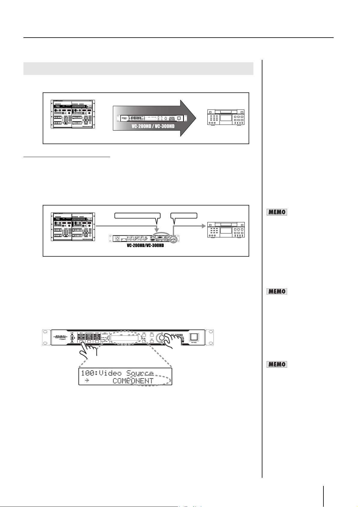
Selecting the video input connector
This unit has multiple video input connectors: i.LINK connector,
COMPONENT connector, DVI-I connector, and HD-SDI connector
(VC-300HD). Simultaneous video input is possible.
When converting a video signal, the connector for the video to be
converted must be selected.
1 Press the INPUT button until "100: Video Source" is
shown in the display
INPUT button
The INPUT button lights, and the screen shown in the figure is
displayed.
2 Use the VALUE/ENTER knob to select the connector
where the video is being input
VALUE/ENTER knob
2 Press the POWER switch on the left side of the front
panel.
3 Press the VALUE/ENTER knob to confirm the selection.
The Status screen returns to the display (p. 29).
When a video signal is input to the selected video input connector,
a video signal is output in the output format set with “Selecting the
video output format” (p. 27).
* When a connector with no input is selected, a black matte image is
output.
* Specify the video input format with the "110: i.LINK IN" (p. 32),
"120: COMPONENT IN" (p. 32), "130: DVD-D IN"(p. 32), "131:
DVI-A IN" (p. 32), and "140: SDI I IN" (p. 32) items of the Menu (p.
30).
26
Page 27

Basic Operations
Selecting the audio input connector
This unit has several sound input connectors: AUDIO INPUT
connectors, i.LINK connector, and HD-SDI connector (VC-300HD
only). At the factory settings, the audio input connector appropriate for
the video selected under "Selecting the video input connector" (p. 26)
is selected.
Use the following procedure to manually select the sound input
connector.
1 Press the INPUT button until "200: Audio Source" is
shown in the display.
INPUT button
The INPUT button lights, and the screen shown in the figure is
displayed.
2 Use the VALUE/ENTER knob to select the connector
where the audio is being input.
Selecting the video output format
The video signal selected with “Selecting the video input connector” on
the page to the left can be converted and output in any video format.
Follow the procedure below to select a video format to output.
1 Press the OUTPUT button until "300: Video Output
Format" is shown in the display
OUTPUT button
The OUTPUT button lights, and the screen shown in the figure is
displayed.
2 Use the VALUE/ENTER knob to select the output
format.
VALUE/ENTER knob
VALUE/ENTER knob
3 Press the VALUE/ENTER knob to confirm the selection.
When sound is input to the selected connector, sound is output from
the AUDIO OUTPUT connectors, i.LINK connector, or HD-SDI OUT
connector (VC-300HD only).
* The same HDV or DV recording is output from CH1/CH2 and CH3/CH4 of
the AUDIO OUTPUT connectors. The embedded audio output from the HDSDI OUT connector at this time is output to the channel selected with "450:
SDI OUT Audio Ch" (p. 37) from the Menu (p. 30).
* When inputting a DV signal (32 kHz, 12 bit, 4-channel) from the i.LINK
connector, select the channel to use in conversion with "170: DV In Audio
Ch" (p. 33) from the Menu (p. 30).
* When sound output from the i.LINK connector is to be output in the 32 kHz,
12 bit, 4-channel format, set "32kHz" with "320: Audio Out Fs" (p. 35) from
the Menu (p. 30). At this time, sound is not output from the HD-SDI OUT
connector.
* Specify the nominal level of the AUDIO INPUT connectors with "161: In
Ch1&2 NomLv" (p. 33) and "162: In Ch3&4 NomLv" (p. 33) from the Menu
(p. 30).
* Specify the nominal level of the AUDIO OUTPUT connectors with "360: Out
Ch1&2 NomLv" (p. 35) and "361: Out Ch3&4 NomLv" (p. 35) from the Menu
(p. 30).
3 Press the VALUE/ENTER knob to confirm the selection.
The Status screen returns to the display (p. 29).
Each output connector outputs video in the selected video format.
* See the “Output Format Table” (p. 13) for combinations of formats
and the connectors that can be output to. Selected video formats
for some combinations do not have connectors where they can be
output.
* If the aspect ratio of the video selected under “Selecting the video
input connector” (p. 26) and that of the output format are different,
select the scaling type with "200: Scaling Type" (p. 33) from the
Menu (p. 30).
27
Page 28

Basic Operations
Test Pattern / Test Tone Output
The VC-300HD/VC-200HD can easily output test patterns or test
tones.
1 Press the OUTPUT button until "390: Test Pattern" or
"391: Test Tone" is shown in the display
Press the PAGE button once to display the test pattern. Press the
PAGE button twice to display the test tone.
OUTPUT button
The OUTPUT button lights, and the screen shown in the figure is
displayed.
2 Use the VALUE/ENTER knob to select the test pattern/
test tone to output.
VALUE/ENTER knob
Setting internal processing
The video aspect ratio, audio delay amount, and audio level can be
adjusted.
1 Press the PROCESSING button until the internal
process item is shown in the display
PROCESSING button
The internal processes that can be selected are of the following 5
types.
Item Name Internal Process Description
200: Scaling Type Sets the aspect ratio. p. 33
210: Out Zoom Adjusts the magnification
of the output video.
240: AudioDelayTime Sets the delay applied to
the output audio.
260: Sync Source Sets the synchronizing
signal input source.
270: TC Generate Selects the timecode to
embed in the HDV, DV, or
HD-SDI output.
p. 34
p. 34
p. 34
p. 34
3 Press the VALUE/ENTER knob to confirm the selection.
The Status screen returns to the display (p. 29).
* When test pattern is selected, each video output connector
outputs a test pattern in the video format selected with “Selecting
the video output format” (p. 27).
2 Press the VALUE/ENTER knob to confirm the value of
the setting
VALUE/ENTER knob
* For the settings for each item, see the "Description" page
indicated in the table.
3 Press the VALUE/ENTER knob to confirm the selection.
The Status screen returns to the display (p. 29).
28
Page 29

Showing the Display
The display shows the status of the device. It also shows the menu
screens for the various settings.
Display
* The display may be difficult to read depending on the angle from
which the unit is viewed. The character contrast on the display and
brightness of the backlight are adjusted with the "900: LCD
Contrast" and "901: Light Dimmer" settings (p. 37) from the Menu
(p. 30).
• Status Screen
* For details see "Status Screen" below.
• Menu Screen
Basic Operations
Video Input/Output Format
Displays the video input/output format.
ba c
a Displays the input connector.
* The input connector is selected with “Selecting the video input
connector” (p. 26).
b Displays the video input format.
* When no video is input to the input connector shown in a., "--------"
is displayed.
c Displays the video output format.
* The video output format is selected with “Selecting the video
output format” (p. 27).
Audio Level CH1, CH2
Audio Level CH3, CH4
* For details, see "Menu Display and Operation" (p. 30).
Panel Lock
When the PANEL LOCK button is lit, “Panel Lock!!” is displayed and
no operations can be performed if any button other than the PAGE
button is pressed. To release panel lock, press and hold down the
PANEL LOCK button for at least two seconds. When panel lock is
released, the PANEL LOCK button goes out.
Status Screen
The Status screen shows the status of the unit. When power to the unit
is turned on, the Status screen is displayed.
There are four types of Status screens. Press the PAGE button to
change the display.
Video Input/Output Format
•
• Audio Level CH1, CH2
• Audio Level CH3, CH4
• Audio Delay
• Timecode
a b
a Displays the connector where audio is being output.
b Displays the input audio level of a. The peak is held for
a set time.
* The audio level cannot be adjusted from this screen. Adjust the
audio level from "330: Audio OutCh1&2 Lv" and "331:
AudioOutCh3&4Lv" (p. 35) from the Menu (p. 30).
* If the audio level is high and the display on the Status screen
exceeds 0 dB, the output audio may be distorted. In this case,
control the audio level on the device inputting audio to this unit or
control the audio level with "330: Audio OutCh1&2 Lv" and "331:
AudioOutCh3&4Lv" (p. 35) on the above Menu (p. 30).
Audio Delay
Displays the amount of audio delay in units of frames. The value in ()
displays the audio delay in milliseconds.
* Set audio delay using the procedure in "Setting internal
processing" (p. 28).
Timecode / User Bit
Displays the time code and user bit output from the i.LINK connector
and HD-SDI OUT connector.
a b d
a Displays the timecode.
* If the frame rate of the input video (p. 26) and the output format (p.
27) are different, the displayed timecode is generated internally.
b Displays the user bit (p. 35).
c Displays drop frame (D) or non-drop frame (ND).
29
Page 30

Basic Operations
Menu Display and Operation
The Menu screen is shown on the display when the MENU button is
pressed. Various settings for the VC-300HD/
VC-200HD are performed on the Menu screen.
MENU button
1 Item Number
2 Item Name
3 Value of Setting
1 2 3
* See “Menus and settings” (p. 32) for items displayed on the Menu
screen.
Item Selection
When the VALUE/ENTER knob is turned while an item number is
blinking, the item number and item name shown on the display
changes.
Changing the Value of a Setting
Press the VALUE/ENTER knob and the setting’s value blinks,
indicating that it can be changed.
Use the VALUE/ENTER knob to change the value of the setting.
The selected value for the setting is confirmed by pressing the VALUE/
ENTER knob. The setting’s value stops blinking and the item number
begins to blink.
VALUE/ENTER knob
* If the EXIT button is pressed while the setting's value is blinking,
the value is not confirmed and the item returns to the selection
status (the item number blinks).
Exiting from the Menu
When the MENU button is pressed while the Menu is being displayed,
the unit exits from the Menu screen and returns to the Status screen
(p. 29).
EXIT button
Press the PAGE button to skip groups of item numbers. Press and hold
down the PAGE button to display the name of the group being skipped.
The following are the groups.
Name Range of
Item Numberson
100 – 170 Input Parameter p. 32
200 – 275 Processing Parameter p. 33
300 – 391 Output Parameter p. 35
400 – 460 SDI Parameter p. 37
900 – 999 System Parameter p. 37
Group Name Descriptions
* If the MENU button is pressed to exit from the Menu while the
setting's value is blinking, the selected value is not used.
Adjusting the Display
The darkness of the text shown in the display and the backlight's
brightness can be adjusted with "900: LCD Contrast" and "901: Light
Dimmer" (p. 37) from the Menu.
30
Page 31

Appendices
31
Page 32

Menus and settings
* See Menu Display and Operation (p. 30) for menu operations.
100–162 Input Parameter
Item
Number
100 Video Source Specifies connector from which video is to be input.
110 i.LINK IN Selects the format of the video input to the i.LINK connector.
120 COMPONENT IN Selects the format of the video input to the COMPONENT INPUT connector.
122 In 480i Setup Sets the video input setup level when 480/59.94i is selected for “120: COMPONENT IN.”
130 DVI-D IN Selects the format of the digital video (DVI-D) input to the DVI-I INPUT connector.
131 DVI-A IN Selects the format of the analog video (DVI-A) input to the DVI-I INPUT connector.
132
133 DVI-A H Position Adjusts the horizontal position of the analog video (DVI-A) input via the DVI-I INPUT connector.
134 DVI-A V Position Adjusts the vertical position of the analog video (DVI-A) input via the DVI-I INPUT connector.
135 DVI-A Frequency Fine tunes the sampling frequency for the analog video (DVI-A) input via the DVI-I INPUT connector.
136 DVI-A Phase Fine tunes the sampling phase for the analog video (DVI-A) input via the DVI-I INPUT connector.
140 SDI IN Selects the format of the video input to the HD-SDI IN connector. [Auto]: Selected automatically.
150 Audio Source Selects the input connector of the audio to be used.
160 AUDIO IN Ch Selects the channels where Sets which channels of the audio output from the AUDIO OUTPUT connectors,
Item Name Description and Available Settings
[i.LINK]: Selects the i.LINK connector.
COMPONENT: Selects the COMPONENT IN connector.
DVI-D: Selects the DVI (Digital) connector.
DVI-A: Selects the DVI (Analog) connector.
SDI: Selects the HD-SDI IN connector. (VC-300HD only)
[Auto]: Selected automatically.
480/59.94i, 576/50i, 720/59.94p, 720/50p, 1080/59.94i, 1080/50i: Select one of these formats.
[Auto]: Selected automatically.
480/59.94i, 576/50i, 480/59.94p, 576/50p, 720/59.94p, 720/50p, 1080/59.94i, 1080/50i: Select one of these
formats.
[0IRE]: Selects 0IRE. (NTSC Japan/PAL)
7.5IRE: Selects 7.5IRE. (NTSC excluding Japan)
[Auto]: Selected automatically.
640 x 480/60, 640 x 480/75, 800 x 600/60, 800 x 600/75, 1024 x 768/60, 1024 x 768/75, 1152 x 864/75,
1280 x 768/60, 1280 x 960/60, 1280 x 1024/60, 1280 x 1024/75, 1360 x 768/60: Select one of these formats.
[Auto]: Selected automatically.
640 x 480/60, 640 x 480/75, 800 x 600/60, 800 x 600/75, 1024 x 768/60: Select one of these formats.
DVI-A AutoConfig
Automatically adjusts the analog video (DVI-A) input to the DVI-I INPUT connector.
When "Please Push [ENTER]" is displayed, press the VALUE/ENTER knob for automatic adjustment. Automatic adjustment automatically changes the values for "133: DVI-A H Position," "134: DVI-A V Position,"
"135: DVI-A Frequency," and "136: DVI-A Phase."
-100–[0]– +100 pixel: Larger values move the image to right.
* This is automatically adjusted when "132: DVI-A AutoConfig" is used.
-100–[0]– +100 line: Larger values move the image up.
* This is automatically adjusted when "132: DVI-A AutoConfig" is used.
-100–[0]– +100 clock: May be adjusted in this range.
* This is automatically adjusted when "132: DVI-A AutoConfig" is used.
-100–[0]– +100: May be adjusted in this range.
* This is automatically adjusted when "132: DVI-A AutoConfig" is used.
480/59.94i, 576/50i, 720/59.94p, 720/50p. 1080/59.94i, 1080/50i: Select one of these formats.
[Auto]: Automatically selects the audio input corresponding to "100: Video Source."
For i.LINK: Selects the audio input to the i.LINK connector.
For COMPONENT: Selects the audio input to the AUDIO INPUT connector.
For DVI-D: Selects the audio input to the AUDIO INPUT connector.
For DVI-D: Selects the audio input to the AUDIO INPUT connector.
For SDI: Selects the audio input to the HD-SDI IN connector. (VC-300HD only)
i.LINK: Selects the audio input to the i.LINK connector.
AUDIO IN: Selects the audio input to the AUDIO INPUT connector.
SDI: Selects the audio input to the HD-SDI IN connector. (VC-300HD only)
HD-SDI OUT connector, and i.LINK connector to assign the audio input to AUDIO INPUT CH1/CH2 and
CH3/CH4.
* Please also set the SDI output assignment to "450: SDI OUT Audio Ch." (VC-300HD only)
CH1/2 CH1/2: Audio output from CH1/CH2 is output to AUDIO IN connector CH1/CH2, and Audio is output from CH3/CH4 output to AUDIO IN connector CH1/CH2.
[CH1/2 CH3/4]: Audio output from CH1/CH2 is output to AUDIO IN connector CH1/CH2, and Audio is output from CH3/CH4 output to AUDIO IN connector CH3/CH4.
CH3/4 CH1/2 : Audio output from CH1/CH2 is output to AUDIO IN connector CH3/CH4, and Audio is output from CH3/CH4 output to AUDIO IN connector CH1/CH2.
CH3/4 CH3/4 : Audio output from CH1/CH2 is output to AUDIO IN connector CH3/CH4, and Audio is output from CH3/CH4 output to AUDIO IN connector CH3/CH4.
32
* The values enclosed in a [box] are the factory defaults.
Page 33

100–162 Input Parameter (continued)
Menus and settings
Item
Number
161 In Ch1&2 NomLv Sets the input Nominal level for AUDIO INPUT connector CH1 and CH2.
162 In Ch3&4 NomLv Sets the input Nominal level for AUDIO INPUT connector CH3 and CH4.
170 DV In Audio Ch Selects the channel with audio output from either the AUDIO OUTPUT connectors or HD-SDI OUT con-
Item Name Description and Available Settings
+4dBu, -2dBu, -4dBu, -10dBu: Larger numerical values indicate higher levels.
+0dBu, -6dBu, -8dBu, -14dBu: Larger numerical values indicate higher levels.
nector when the DV input audio input via the i.LINK connector is 4-channel (32 kHz).
* This setting is ignored when the DV input audio is 2-channel (48 kHz).
200–275 Processing Parameter
Item
Number
200 Scaling Type Sets the scaling type.
Item Name Description and Available Settings
[Squeeze]: Uses the same aspect ratio as the input.
4:3 NTSC / 480i
PAL / 576i, 1024 x 768
800 x 600, 640 x 480
4:3 (Letterbox)
NTSC / 480i
PAL / 576i
4:3 (Squeeze)
NTSC / 480i
PAL / 576i
16:9
1080i
720p
Side Panel/Let Box: Shows the entire image, with black shown in portions where there is no video image.
4:3, NTSC / 480i
PAL / 576i. 1024 x 768
800 x 600. 640 x 480
4:3 (Letterbox)
NTSC / 480i
PAL / 576i
4:3 (Squeeze)
NTSC / 480i
PAL / 576i
16:9
1080i
720p
Crop: Displays the image so as to fill the entire screen; does not show the portions extending outside.
4:3, NTSC / 480i
PAL / 576i, 1024 x 768
800 x 600, 640 x 480
Original Image 4:3 16:9
→
→
→
→
→
→
→
→
→
4:3 (Letterbox)
NTSC / 480i
PAL / 576i
4:3 (Squeeze)
NTSC / 480i
PAL / 576i
16:9
1080i
720p
* The values enclosed in a [box] are the factory defaults.
→
→
→
33
Page 34

Menus and settings
200–275 Processing Parameter (continued)
Item
Number
210 Out Zoom Adjusts the magnification of the output video.
211 Out H Position Adjusts the horizontal position of the output video when the aspect ratios of the input video (p. 26) and
212 Out V Position Adjusts the vertical position of the output video when the aspect ratios of the input video (p. 26) and the
220 Noise Reduction Obscures noise in the input video so it is unnoticeable. If it is set too strong, the video resolution may be
221 Enhancement Emphasizes the edges of the input video. If set too strong, the edges may look jagged.
222 Video Red Gain Sets the gain value for red in the video being output.
223 Video Green Gain Sets the gain value for green in the video being output.
224 Video Blue Gain Sets the gain value for blue in the video being output.
240 AudioDelay Time Sets the delay applied to the output audio.
250 Audio Low Gain Sets the low-range gain value for the sound being output.
251 Audio Mid Gain Sets the mid-range gain value for the sound being output.
252 Audio High Gain Sets the high-range gain value for the sound being output.
260 Sync Source Sets the synchronizing signal input source.
261 Sync Adjust Fine tunes the synchronizing signal.
270 TC Generate Selects the timecode to embed in the HDV, DV, or HD-SDI output.
271 TC Offset Sets the offset to apply when “Offset” is selected with “270: TC Generate.” This value will be the time
Item Name Description and Available Settings
50–[100]–200%: Larger numerical values make the image larger.
* The maximum value that can be selected changes according to the combination of the input video format (p. 26)
and the output format (p. 27).
the output format (p. 27) are different and "Side Panel/Let" or "Crop" is selected with "200: Scaling Type."
-100–[0]– +100 %: Larger values move the image right.
output format (p. 27) are different and "Side Panel/Let" or "Crop" is selected with "200: Scaling Type."
-100–[0]– +100 lines: Larger values move the image up.
reduced.
[Off]: Do not use 1–63:
The strength of the Noise Reduction
[Off]: Do not use
1–63: Strength of Enhancement
[0]–100%: Larger numerical values indicate a stronger red color.
[0]–100%: Larger numerical values indicate a stronger green color.
[0]–100%: Larger numerical values indicate a stronger blue color.
0.00–[1.00]–15.00f
* The time per frame changes according to the frame rate in the value set in "300:Video Out Format."
Therefore, the range of values displayed on the screen (???.? ms) is as follows.
-When the frame rate is 59.94i/59.94p
-When the frame rate is 50i/50p
-12dB–[0]– +12dB:
Increasing the numerical value increases the low-range gain value.
-12dB–[0]– +12dB: Increasing the numerical value increases the mid-range gain value.
-12dB–[0]– +12dB: Increasing the numerical value increases the high-range gain value.
[Auto]: Selected automatically.
REF Input: Selects the REF INPUT connector.
Video Input: Selects the video being used.
Internal: Uses the synchronizing signal generated internally.
-1000–[0]– +1000 clock: May be adjusted in this range.
* On the VC-200HD, this is set to "Off" at the factory.
[Off]: Time code is not embedded. Free Run: Timecode is generated internally. The timecode is generated
from when the power is turned on or when “271: TC Offset” is set.
Free Run: The time code starts (preset) from the moment settings are made with "271: TC Offset."
[Thru]: Use the timecode input from an external source. The timecode that is used will be that which is
embedded in the signal of the video connector being used.
* This setting is ignored when the frame rates of the input video (p. 26) and the output format (p. 27) are different.
The time code output here is the same as when "Free Run" is set.
Offset: Output the timecode input from an external source with the offset set with “271: TC Offset” appended to it. The TC that is used will be that which is embedded in the signal of the video connector being
used.
code's preset value when "Free Run" is set for "270: TC Generate."
The hour (h), minute (m), second (s), and frame (f) values can be set independently for this item.
[00h00m00s00f]–23h59m59s24f
[00h00m00s00f]–23h59m59s29f
* The available range for this parameter changes when the "300: Video Out Format" parameter is changed.
* When "Free Run" is set for "270: TC Generate," the time code count is reset when this item setting is changed.
(When the frame rate value set for "300:Video Out Format" is 50i or 50p)
(When the frame rate value set for "300:Video Out Format" is 59.94i or 59.94p)
34
* The values enclosed in a [box] are the factory defaults.
* For items 201-212 and 220-224, please adjust while confirming on a video monitor.
Page 35

200–275 Processing Parameter (continued)
Menus and settings
Item
Number
274 User Bit Sets the user bit embedded in the timecode when "Free Run" is set with "270: TC Generate."
275 Drop Frame Selects drop frame/non-drop frame for the time code when "Free Run" is set with "270: TC Generate."
Item Name Description and Available Settings
* Because there is no impact when the value set for "270: TC Generate" is not "Free Run," the input user bit is
passed through without any change. If no user bit is input, "FF FF FF FF" is output.
This item sets each value independently.
[00]–FF, [00]- FF, [00]–FF, [00]- FF: May be adjusted in this range.
[Drop]: Selects Drop Frame.
Non Drop: Selects Non-drop Frame.
* The setting is not valid when "1080/50p," "1080/50i," "720/50p," "576/50p," or "576/50i" is selected with
"300: Video Out Format."
* The values enclosed in a [box] are the factory defaults.
300–391 Output Parameter
Item
Number
300 Video Out Format Selects the format of the video to output. [Auto]: One of the following formats is automatically selected,
311 Out 480i Setup Sets the video output setup level of the COMPONENT OUT connector when 480/59.94i is selected for
320 Audio Out Fs Sets the sampling frequency of the digital audio output from the i.LINK connector or HD-SDI OUT con-
330
331
340 Audio Out Mode Sets the audio mode of the audio output from the AUDIO OUT connector
350
351
360 DV Locked Audio When outputting with the DV format from the i.LINK connector, sound is output with “Locked Audio.”
Item Name Description and Available Settings
so as to match the format of the input video.
1080/59.94p, 1080/50p, 1080/59.94i, 1080/50i, 720/59.94p, 720/50p, 480/59.94p, 576/50p, 480/59.94i,
576/50i: Select one of these formats.
* If "Auto" is set or if "Free Run" is set with "270: TC Generate" of the video input being used, the time code count
is reset when this item setting is changed
“300: Video Out Format.”
[0IRE]: Selects 0IRE. (NTSC Japan/PAL)
7.5IRE: Selects 7.5IRE. (NTSC excluding Japan)
nector.
[48 kHz]: Outputs audio in 48 kHz.
32 kHz: Outputs audio in 32 kHz. If "480/59.94i" or "576/50i" is selected with "300: Video Out Format" at
this time, the output from the i.LINK connector is a DV signal and the audio is 4 channel. If anything else
is set, no video is output from the i.LINK connector.
AudioOutCh1&2Lv
AudioOutCh1&2Lv
Out Ch1&2 NomLv
Out Ch3&4 NomLv
Sets the audio output level for AUDIO OUTPUT connectors CH1 and CH2.
Mute: Mutes the audio.
-40 dB –[0]– +12 dB: Adjusts the sound output level.
Sets the audio output level for AUDIO OUTPUT connectors CH3 and CH4.
Mute: Mutes the audio.
-40 dB –[0]– +12 dB: Adjusts the sound output level.
[2Ch]: Outputs 2 channels.
4Ch: Outputs 4 channels.
Sets the output Nominal level for AUDIO OUTPUT connectors CH1 and CH2.
[+4dBu], -2dBu, -4dBu, -10dBu: Larger numerical values indicate higher levels.
Sets the output Nominal level for AUDIO OUTPUT connectors CH3 and CH4.
[+0dBu], -6dBu, -8dBu, -14dBu: Larger numerical values indicate higher levels.
[Off]: Do not use locked audio.
On: Use locked audio.
* The values enclosed in a [box] are the factory defaults.
* For items 350 and 351, please adjust while confirming on a monitor speaker.
35
Page 36

Menus and settings
300–391 Output Parameter (continued)
Item
Number
390 Test Pattern Displays the test pattern.
Item Name Description and Available Settings
[Off]: No test pattern is displayed.
75%: Displays a 75% color bar.
100%: Displays a 100% color bar.
Hatch: Displays a cross hatch.
391 Test Tone Outputs a test tone from the AUDIO OUT connector, i.LINK connector, and HD-SDI connector.
[Off]: The test tone is not output.
-20dB@1 kHz: Output at -20dB and 1 kHz.
-10dB@1 kHz: Output at -10dB and 1 kHz.
0dB@1 kHz: Output at 0dB and 1 kHz.
Note: For item numbers 351, 353, and 354, please adjust whilee confirming with
headphones.
Note: The values enclosed in a [box] are the factory defaults.
36
Page 37

400–452 SDI Parameter
Menus and settings
Item
Number
400 SDI IN AudioCh Selects the channels to be used for conversion with "AUDIO PROCESSOR [CH A&B] " or "AUDIO PRO-
401 SDI IN TC Selects the type of embedded Timecode to be input to the HD-SDI IN connector.
450 SDI OUT AudioCh Selects the channels to be used for conversion with "AUDIO PROCESSOR [CH A&B] " or "AUDIO PRO-
451 SDI OUT TC Selects the type of embedded Timecode to be output from the HD-SDI IN connector.
Item Name Description and Available Settings
CESSOR [CH C&D] " (p. 43) from the embedded audio input via the HD-SDI IN connector.
AB:1/2 CD:1/2: Channels 1 and 2 are used for [CH A&B], and channels 1 and 2 are used for [CH C&D].
[AB:1/2 CD:3/4]: Channels 1 and 2 are used for [CH A&B], and channels 3 and 4 are used for [CH C&D].
AB:1/2 CD:5/6: Channels 1 and 2 are used for [CH A&B], and channels 5 and 6 are used for [CH C&D].
AB:1/2 CD:7/8: Channels 1 and 2 are used for [CH A&B], and channels 7 and 8 are used for [CH C&D].
AB:3/4 CD:1/2: Channels 3 and 4 are used for [CH A&B], and channels 1 and 2 are used for [CH C&D].
AB:3/4 CD:3/4: Channels 3 and 4 are used for [CH A&B], and channels 3 and 4 are used for [CH C&D].
AB:3/4 CD:5/6: Channels 3 and 4 are used for [CH A&B], and channels 5 and 6 are used for [CH C&D].
AB:3/4 CD:7/8: Channels 3 and 4 are used for [CH A&B], and channels 7 and 8 are used for [CH C&D].
AB:5/6 CD:1/2: Channels 5 and 6 are used for [CH A&B], and channels 1 and 2 are used for [CH C&D].
AB:5/6 CD:3/4: Channels 5 and 6 are used for [CH A&B], and channels 3 and 4 are used for [CH C&D].
AB:5/6 CD:5/6: Channels 5 and 6 are used for [CH A&B], and channels 5 and 6 are used for [CH C&D].
AB:5/6 CD:7/8: Channels 5 and 6 are used for [CH A&B], and channels 7 and 8 are used for [CH C&D].
AB:7/8 CD:1/2: Channels 7 and 8 are used for [CH A&B], and channels 1 and 2 are used for [CH C&D].
AB:7/8 CD:3/4: Channels 7 and 8 are used for [CH A&B], and channels 3 and 4 are used for [CH C&D].
AB:7/8 CD:5/6: Channels 7 and 8 are used for [CH A&B], and channels 5 and 6 are used for [CH C&D].
AB:7/8 CD:7/8: Channels 7 and 8 are used for [CH A&B], and channels 7 and 8 are used for [CH C&D].
LTC: Selects the LTC.
[VITC]: Selects the VITC.
CESSOR [CH C&D] " (p. 43) from the embedded audio input via the HD-SDI IN connector.
[AB:1/2 CD:3/4]: Channels 1 and 2 are used for [CH A&B], and channels 3 and 4 are used for [CH C&D].
AB:1/2 CD:5/6: Channels 1 and 2 are used for [CH A&B], and channels 5 and 6 are used for [CH C&D].
AB:1/2 CD:7/8: Channels 1 and 2 are used for [CH A&B], and channels 7 and 8 are used for [CH C&D].
AB:3/4 CD:1/2: Channels 3 and 4 are used for [CH A&B], and channels 1 and 2 are used for [CH C&D].
AB:3/4 CD:5/6: Channels 3 and 4 are used for [CH A&B], and channels 5 and 6 are used for [CH C&D].
AB:3/4 CD:7/8: Channels 3 and 4 are used for [CH A&B], and channels 7 and 8 are used for [CH C&D].
AB:5/6 CD:1/2: Channels 5 and 6 are used for [CH A&B], and channels 1 and 2 are used for [CH C&D].
AB:5/6 CD:3/4: Channels 5 and 6 are used for [CH A&B], and channels 3 and 4 are used for [CH C&D].
AB:5/6 CD:7/8: Channels 5 and 6 are used for [CH A&B], and channels 7 and 8 are used for [CH C&D].
AB:7/8 CD:1/2: Channels 7 and 8 are used for [CH A&B], and channels 1 and 2 are used for [CH C&D].
AB:7/8 CD:3/4: Channels 7 and 8 are used for [CH A&B], and channels 3 and 4 are used for [CH C&D].
AB:7/8 CD:5/6: Channels 7 and 8 are used for [CH A&B], and channels 5 and 6 are used for [CH C&D].
* You cannot select the same channel for "AUDIO PROCESSOR [CH A&B]" and "AUDIO PROCESSOR
[CH C&D."
LTC: Selects the LTC.
[VITC]: Selects the VITC.
Note: The values enclosed in a [box] are the factory defaults.
900–999 System Parameter
Item
Number
900 LCD Contrast Adjusts the display contrast.
901 Light Dimmer Adjusts the brightness of the display backlighting.
999 Factory Reset Resets the settings to the factory defaults. When "Are you sure?" is displayed, press the VALUE/ENTER
* The values enclosed in a [box] are the factory defaults.
Item Name Description and Available Settings
0–[7]–10
0–[7]–10
knob to reset.
37
Page 38

Input / Output Signal
HDV
HDV (High Definition Video) is the standard term used for the format to
record High-definition television (HDTV) onto DV tape used in digital
video cameras.
HDV uses MPEG-2 for video compression. DV uses a method that
compresses each video frame individually, but HDV realizes high
definition recording with the same data volume as DV by using MPEG2 inter-frame prediction. Because of this, although high definition video
has considerably more data than SD video, it can secure the same
amount of recording time as DV.
MPEG-1 Audio Layer-2 is used for audio compression. The sampling
frequency is 48 kHz, and the 16-bit stereo audio is compressed with a
bit rate of 384 kbps.
The “HDV Standard” defines two types: “HDV 1080i,” interlaced
scanning with 1080 lines of effective scan lines, and “HDV 720p,” 720
lines of progressive scanning.
HDV 1080i
The HDV1080i method compresses with about 25 Mbps MPEG-2
video and records 1440 x 1080 pixels, interlaced video of 60/50 fields
per second (NTSC/PAL).
HDV 720p
The HDV 720p method compresses with about 19 Mbps MPEG-2
video and records 1280 x 720 pixels, progressive video of 30 or 60/25
or 50 frames per second (NTSC/PAL).
SDI
SDI (serial digital interface) is a standard defined by SMPTE (Society
of Motion Picture and Television Engineers) and is used widely today
in the broadcast and video production industries. The SDI standard
prescribes methods for transmitting non-compressed serial digital
video data using a BNC cable (video coaxial cable) between devices
in the production facility.
The SDI standard is of two types: standard definition (SD) SDI and high
definition (HD) SDI.
DV
DV (Digital Video) is the SD television image quality digital video
standard. It supports both NTSC and PAL TV standards. One frame of
data has video and audio combined. The bit rate is about 27 Mbps.
Video compression is only performed with interlaced. Because
compression is not performed along the time axis, as with MPEG,
compression is about 1/5, but a merit is that video editing can be
performed simply at the frame level.
Audio has sampling frequencies of 48/44.1/32 kHz with noncompressed linear PCM. The quantization bit rate is 16 bit in stereo. In
32 kHz mode, the quantization bit rate is 12 bits, so four-channel
recording is possible.
DVI
DVI (Digital Visual Interface) is a video output interface standard
designed for maximizing image quality on display devices that focus on
digital video, such as LCD monitors. This standard is designed to send
uncompressed digital video data to the display. There is also partial
compatibility with the HDMI standard. It also supports analog video
interfaces (VGA signals) for existing CRT displays, as well as digital
interfaces.
The DVI connector on a device can have one of three names,
depending on the signals it carries.
DVI-D (digital)
DVI-A (analog)
DVI-I (digital and analog)
Note: According to the standard, a cable length of up to 5 meters is
permissible.
HDMI
HDMI (High-Definition Multimedia Interface) is for AV home electronics
that adds audio transmission functionality, copyright protection
functionality, and color difference transmission functionality to DVI. To
input HDMI to this device, use a separately purchased DVI-I HDMI
conversion cable and connect it to the DVI connector.
If a DVI-I HDMI conversion cable is used, then the audio output with
HDMI is not output to the DVI side.
RGB
This is one of the video outputs for computers and is sometimes called
VGA output or analog output. In general, it is output using a D-Sub 15pin (DB-15) connector. For this device, a commercially available DVI
adapter (VGA-DVI) can be used in the DVI-I connector for input.
Interlaced and Progressive
Video gives the appearance of movement
by continuously displaying screens
(frames) within a fixed time. To transmit
screens with an electronic signal, the
image is cut into numerous horizontal
lines as shown in the figure and is
transmitted as "threads" of electronic
signals. These "threads" are called scan
lines. There are two methods of arranging
scan lines: the "interlaced method (i)" and
the "progressive method (p)." (See figure
at right.)
The interlaced method divides the fields
into ODD and EVEN fields and transfers
them at a rate of 59.94 fields per second
for NTSC. The two fields are displayed
alternately, but the image appears to
move smoothly with the 59.94 frames due to the image persistence of
human vision. The actual number of frames (frame rate) displayed
each second is 29.97 frames for NTSC and 25 frames for PAL.
The progressive method scans screens without interlacing and
displays images in frame units. For example, with 720/59.94p, 59.94
image frames are displayed each second; with 720/50p, 50 image
frames are displayed each second. However, the time code is the
same as for the interlaced method, so when the time code advances
one frame, the progressive method video advances two frames.
Interlace scan
EVEN field
ODD field
Progressive scan
38
Page 39

Installation and Maintenance
Installing and Removing the Rack Mount Fittings
The rack mounts fittings for this device can be installed or removed.
Cautions regarding removing the rack mount fittings
• Please use a Phillips screwdriver that fits the screw head (No. 2
screwdriver). If the screwdriver does not fit the screw head, then the
screw head may become stripped.
• To remove the screws, turn the screwdriver in a counterclockwise
direction. To tighten the screws, turn the screwdriver in a clockwise
direction.
tightenloosen
928
• When turning this unit over, place newspapers or magazines under
the four corners or under both sides to prevent damage to the
buttons and knobs. Also, position the unit so that the buttons and
knobs won’t get damaged.
929
• When turning the unit upside-down, handle with care to avoid
dropping it, or allowing it to fall or tip over.
• When removing the rack mount fittings, remove only the specified
screws.
How to remove the rack mount fittings
Daily Maintenance
Forced air cooling is inhibited if the cooling fan’s intake vent or exhaust
vent becomes blocked with dust and the airflow is impeded.
Periodically use a vacuum cleaner to clear out dust from the cooling
fan’s exhaust vent and intake vent.
Fan
If the cooling fan mounted in this device should become damaged, the
device may be subject to overheating, because proper cooling cannot
occur. If you suspect that the cooling fan is not operating properly,
contact the retailer where the unit was purchased or a service center
listed on the back of the warranty envelope.
1 Before removing the rack mount fittings, turn off power
to this unit and to all connected devices and then
unplug the power cord and all connected cables.
2 Remove only the screws indicated in the next figure
and then remove the rack mount fittings. A total of six
screws on the left and right are removed.
Rack mount fitting
(Bottom chassis)
Screws to be removed
3 Replace the screws removed in Step 2 to their original
location.
* To attach the rack mount fittings, follow the above procedure in
reverse. After attaching, check again that the fittings are attached
correctly.
39
Page 40

Troubleshooting
If damage is suspected, please check the following again. If the
problem persists after checking the following, please consult with a
service center (listed on the back of the warranty envelope) or the
retailer from whom this device was purchased.
Video
No video is output
● Is the equipment properly connected?
Check that all devices are connected properly.
➔
● Is the proper output format selected?
If the video output of this unit is not in a format supported by the
➔
connected equipment, the video from this device may not be
output.
➔ Check the formats supported by the connected equipment, and
reselect the video format with the OUTPUT button or from the
Menu.
* See “Selecting the video output format” (p. 27).”
The output video is distorted
● Is the input video, output format, or internal processing
being directly switched?
➔
The processing method is being set within the unit. Please wait
until the video stabilizes.
● Is the video being output in a format that the connected
device does not support?
➔
If the video output of this unit is not in a format supported by the
connected equipment, the video may be distorted.
➔ Check the formats supported by the connected equipment, and
reselect the video format with the OUTPUT button or from the
Menu.
* See “Selecting the video output format” (p. 27).
● Is it possible that the signal being input via the i.LINK
connector contains errors?
➔
When the HDV signal or DV signal contains errors, this unit is
not capable of correcting them.
The video moves in a jerky fashion
● Is the input video frame rate different from the output
format?
➔
When video that has a different frame rate than what has been
set for the output format is input, some jerkiness may
occasionally be exhibited as the result of the frame rate
conversion process. For example, if video with a frame rate of
59.94, as with NTSC, is input, and the frame rate of the output is
50, as with 1080/50i, then 1 out of every 6 frames is not
displayed and the video is jerky.
* See “Selecting the video input connector” (p. 26), “Selecting the
video output format” (p. 27).
The HDV signal is not output
● Is "320: Audio Out Fs" of the Menu (p. 30) set to "32kHz?"
➔
Set it to "48kHz."
No signal is input to the HDV or DV device
● Is input detected with the HDV or DV signal connected to
this unit with the i.LINK cable (IEEE 1394 cable)?
➔
Check the i.LINK cable (IEEE1394 cable) connection.
➔ If the connection is verified, after checking the output format
(p. 27), turn power off to this unit and then restart it.
The HDV device does not accept the HDV signal
output from this device
● Does the output format support the HDV device?
When the output format selected by pressing the OUTPUT
➔
button (p. 10) is not supported by the HDV device, some HDV
devices may not display the video even if the HDV signal is
received. Please select a format supported by the HDV device
being used.
* See “Selecting the video output format” (p. 27).
Audio
There is no audio
● Is audio being input?
➔
Check to see that this device and the connected device are
turned on.
➔ Check to see that this device and the connected device have the
volume turned on.
➔ Check that the cables are connected.
The volume of the device connected to the AUDIO
INPUT connector is low
926a
● The volume level of the instrument connected to AUDIO
INPUT is too low.
➔
Could you be using a connection cable that contains a resistor?
Use a connection cable that does not contain a resistor.
● Does the connecting cable contain a resistor?
➔
Use a connecting cable that doesn’t contain a resistor (such as
one from the Roland PCS series).
The video lags behind the audio
● Does the video input to this device pass through a video
mixer?
➔
Video that passes through a device such as a video mixer or a
frame synchronizer has a delay on the output video.
➔ When passing through lip sync, please use this device’s audio
delay feature.
* See “AudioDelay Time” (p. 34).
The sound is distorted
● Is the sound level input into this device being clipped?
➔
Check the sound level of the input to this device on the Status
screen (p. 29). If the maximum sound level is clipped, the input
sound will be distorted. In these cases, either turn down the
sound level on the connected device or adjust “p. 33” from the
menu on this device.
Miscellaneous
The SDI signal cannot be captured with non-linear software
(VC-300HD only)
● Is the time code being output?
➔
Some non-linear software will terminate capture if the time code
is lost. Set "270: TC Generate" of the Menu (p. 30) to output the
time code.
If a signal with embedded time code, such as an SDI signal, is
set in the input when using VC-300HD, set to "Thru" or "Offset."
When using the VC-200HD or when setting a signal that does
not have embedded time code, such as a composite signal or a
DVI-I signal, with the VC-300HD, set to "Free Run."
40
Page 41

Main Specifications
VC-200HD / VC-300HD: MULTI-FORMAT CONVERTER
Video Input Format
❥ IEEE1394 (i.LINK)
HDV: 1080/59.94i, 1080/50i, 720/59.94p, 720/50p
DV: 480/59.94, 576/50
❥ Component
Y/Pb/Pr: 1080/59.94i, 1080/50i, 720/59.94p, 720/50p,
480/59.94p, 576/50p, 480/59.94i, 576/50i
❥ DVI-I
Digital (RGB):
1600x1200/60Hz, 1400x1050/60/75Hz,
1280x1024/60/75Hz, 1280x768/60Hz,
1280x960/60Hz, 1152x864/75Hz,
1024x768/60/75Hz, 800x600/60/75Hz,
640x480/60/75Hz
Analog (Y/Pb/Pr):
1024x768/60Hz, 800x600/60/75Hz,
640x480/60/75Hz
❥ HD-SDI/SDI (VC-300HD Only)
1080/59.94i, 1080/50i, 720/59.94p, 720/50p,
480/59.94i, 576/50i
❥ REF: BNC Type Black Burst, BiLevel, TriLevel Sync
Video Sampling Rate:
SD: 4:4:4 (Y/Cb/Cr), 10 bits, 13.5 MHz
HD: 4:4:4 (Y/Pb/Pr), 10 bits, 74.1758 MHz/74.25 MHz
RGB: 4:4:4 (R/G/B), 10 bits, 25 MHz to 90 MHz
Audio Input
❥ IEEE1394
HDV: MPEG1 Layer II 16 bit 48 k Hz 384 k bps
DV: Linear PCM 16 bit 48 k Hz,
Nonlinear PCM 12 bit 32 k Hz(2ch)
❥ Analog
Balanced XLR Type (ch1,ch2):
+4 dBu, -2 dBu, -4 dBu, -10 dBu Selectable
Unbalanced RCA phono type(ch3,ch4):
+0 dBu, -6 dBu, -8 dBu, -14 dBu Selectable
Audio Sampling Rate: 24 bit, 48 k Hz / 32 k Hz
❥ HD-SDI/SDI Embedded Audio (VC-300HD Only)
Linear PCM 24 bit 48 k Hz
Audio Output
❥ IEEE1394
HDV: MPEG1 Layer II 16 bit 48 k Hz 384 kbps
DV : Linear PCM 16 bit 48 k Hz,
Nonlinear PCM 12 bit 32 k Hz(2ch)
❥ Analog
Balanced XLR Type (ch1,ch2:
+4 dBu, -2 dBu, -4 dBu, -10 dBu Selectable
Unbalanced RCA phono type(ch3,ch4):
+0 dBu, -6 dBu, -8 dBu, -14 dBu Selectable
Audio Sampling Rate: 24 bit, 48 k Hz / 32 k Hz
❥ HD-SDI/SDI Embedded Audio (VC-300HD Only)
Linear PCM 24 bit 48 k Hz
Video Output Format
❥ IEEE1394 (i.LINK)
HDV: 1080/59.94i, 1080/50i, 720/59.94p, 720/50p
DV: 480/59.94i, 576/50i
❥ Component
Y/Pb/Pr: 1080/59.94p, 1080/50p, 1080/59.94i, 1080/50i,
720/59.94p, 720/50p, 480/59.94p, 576/50p,
480/59.94i, 576/50i
❥ DVI-I
Digital (RGB):
1080/59.94p, 1080/50p, 1080/59.94i,
1080/50i, 720/59.94p, 720/50p,
480/59.94p, 576/50p, 480/59.94i, 576/50i
Analog (Y/Pb/Pr):
1080/59.94p, 1080/50p, 1080/59.94i,
1080/50i, 720/59.94p, 720/50p, 480/59.94p,
576/50p, 480/59.94i, 576/50i
❥ HD-SDI/SDI (VC-300HD Only)
1080/59.94i, 1080/50i, 720/59.94p, 720/50p,
480/59.94i, 576/50i
❥ REF: BNC Type, Loop Thru Output
Processing
❥ Video Processing
Scaling:
Scaling between the specified input and output
Frame Sync:
Built in frame synchronizer and genlock to external
device
Frame Rate Conversion:
from 59.94 to 50 Hz etc.
I/P Conversion:
De-interlace function built-in
❥ Audio Processing
Delay:
Adjustment with Milli-Second or Frame
Sample Rate Conversion:
from 32 to 48 k Hz etc.
41
Page 42

Main Specifications
Video Connectors
IEEE1394 Connector(i.LINK)
6-pin Type, conforms to IEEE1394, HDV standards, Same
connector on front and rear
❥ COMPONENT Input Connector
HD/SD Y/Pb/Pr BNC Type 75 ohms, BiLevel, TriLevel Sync
❥ DVI-I Input Connector
DVI 29pin single link RGB (8 bit each)
Digital RGB dot clock: 25-161MHz (VGA to UXGA)
Analog RGB: R/G/B 0.7 Vp-p, 75 ohms, H/V 5VTTL, RGB dot
clock: 25-90MHz(VGA to XGA)
❥ HD-SDI/SDI Input Connector (VC-300HD Only)
BNC Type Supports embedded audio
Conforms to SMPTE259M, SMPTE272M, SMPTE292M,
SMPTE299M
❥ COMPONENT Output Connector
HD/SD Y/Pb/Pr BNC Type 75 ohms, BiLevel, TriLevel Sync
❥ DVI-I Output Connector
DVI 29pin single link RGB (8 bit each)
Digital RGB: same timing as analog component
Analog Component: Y/Pb/Pr 75 ohms
(0 dBu = 0.775 V rms)
962a
* In the interest of product improvement, the specifications and/or
appearance of this unit are subject to change without prior notice.
Exterior Dimensions Diagram
430
41.0 3.5
13
309
8
331
❥ HD-SDI/SDI Output Connector (VC-300HD Only)
BNC Type Supports embedded audio
Conforms to SMPTE259M, SMPTE272M, SMPTE292M,
SMPTE299M
Audio Connectors
Input Jacks 1ch, 2ch XLR type, 20 k ohms
Input Jacks 3ch, 4ch RCA phono type, 20 k ohms
Output Jacks 1-2 XLR type, 600 ohms
Output Jacks 3-4 RCA phono type, 1 k ohms
Power Supply
AC 117 V, AC 230 V, AC 240 V (50/60 Hz)
AC 220 V (60 Hz)
Power Consumption
60 W
Dimensions
482(430 without Rack Mount Bracket) (W) x 309 (D) x 44 (H) mm
19(16-15/16 without Rack Mount Bracket) (W) x 12-3/16 (D) x 13/4 (H) inches
* EIA-1U Rack Mount Size
44.0 48
4
481.0
Note: Measurements are with the rubber feet (included) attached.
Note: The power cord is not included.
Weight
4.5 kg
9 lbs 15 oz
Accessories
Owner's Manual
Rubber feet x 4
Power Cord
42
Page 43

VC-200HD Block Diagram
I IN
-
DIGITAL
ANALOG
HDV DV
/
i.LINK IN OUT
/
FRONT REAR
Main Specifications
DIGITAL
ANALOG
DVI
-
I OUT COMPONENT OUT
Y
Pb
COMPONENT IN DVI
SDI
HD
REF INAUDIO IN
Pr
)
SDI IN
Embedded Audio
)(
CH1
CH2
BALANCED
(
CH3
CH4
AD
/
SDI
Rx
MODULE
AD
/
TC TC
ENCODE DECODE
VIDEO PROCESSOR
UP DOWN CONVERSION
/
FORMAT CONVERSION
FRAME SYNCRONIZER
COLOR LEVEL ADJUST
NOISE REDUCTION
AUDIO PROCESSOR
DELAY
3BAND EQUALIZER
GAIN ADJUST
SAMPLING RATE CONVERT
HDV DV
/
i.LINK IN OUT
/
FRONT REAR
DA
/
SDI
Tx
MODULE
DA
/
CH1
CH2
CH3
CH4
Y
Pb
Pr
(
Embedded Audio
SDI OUT
HD
-
SDI
)(
REF OUT
BALANCED
AUDIO OUT
)
I IN
-
COMPONENT IN DVI
REF INAUDIO IN
)
BALANCED
(
DIGITAL
ANALOG
Y
Pb
Pr
CH1
CH2
CH3
CH4
AD
/
AD
/
ENCODE DECODE
VIDEO PROCESSOR
/
UP DOWN CONVERSION
FORMAT CONVERSION
FRAME SYNCRONIZER
COLOR LEVEL ADJUST
NOISE REDUCTION
AUDIO PROCESSOR
DELAY
3BAND EQUALIZER
GAIN ADJUST
SAMPLING RATE CONVERT
DA
/
DA
/
DIGITAL
ANALOG
CH1
CH2
CH3
CH4
DVI
-
I OUT COMPONENT OUT
Y
Pb
Pr
REF OUT
(
BALANCED
AUDIO OUT
)
43
Page 44

Main Specifications
DELAY
3BAND EQ
DELAY
3BAND EQ
VC-300HD Block Diagram
HDV DV
- For items enclosed by , the settings can be changed via a menu (p. 30).
- The number and name shown for items enclosed by are the menu number and menu name.
AUDIO IN
CH3&4
162
In Ch3&4 NomLv
CH1&2
C&D
PROCESSOR
[CH C&D]
AUDIO
161
In Ch1&2 NomLv
160
AUDIO In Ch
CH
DELAY
/
i.LINK IN OUT
/
CH1&2
CH3&4
CH
A&B
[CH A&B]
Audio Source
VC-200HD AUDIO BLOCK DIAGRAM
170
DV In Audio Ch
150
PROCESSOR
AUDIO
AUDIO IN
CH3&4
162
In Ch3&4 NomLv
CH1&2
161
In Ch1&2 NomLv
160
AUDIO In Ch
PROCESSOR
[CH C&D]
CH
C&D
AUDIO
HD-SDI
SDI IN
(
Embedded Audio
CH5&6
CH7&8
CH
A&B
DEL
DELAY
CH1&2
CH3&4
[CH A&B]
HDV DV
i.LINK IN OUT
)
CH3&4
400
SDI IN Audio Ch
150
Audio Source
PROCESSOR
AUDIO
/
/
CH1&2
VC-300HD AUDIO BLOCK DIAGRAM
170
DV In Audio Ch
Generator
Test Tone
391
Test Tone
351
Out Ch3&4 NomLv
CH3&4
C&D
331
AudioOutCh3&4Lv
CH1&2
3BAND EQ
A&B
CH
350
Out Ch1&2 NomLv
CH
330
AudioOutCh1&2Lv
Meter
Level
CH1&2
CH3&4
Audio
Test Tone
351
Out Ch3&4 NomLv
CH3&4
391
CH1&2
Generator
Test Tone
350
Out Ch1&2 NomLv
3BAND EQ
CH
C&D
331
AudioOutCh3&4Lv
A&B
CH7&8
)
CH
CH3&4
CH5&6
330
AudioOutCh1&2Lv
450
SDI OUT Audio Ch
CH1&2
Embedded Audio
(
Meter
Level
CH3&4
Audio
CH1&2
44
AUDIO OUT
i.LINK IN OUT
/
HDV DV
/
AUDIO OUT
SDI
-
SDI OUT
HD
i.LINK IN OUT
/
HDV DV
/
Page 45

Output Format Support Chart
The following lists the video formats that can be output with the output connectors mounted on this device.
Main Specifications
Format/Output
Connector
1080/59.94p
1080/50p
1080/59.94i
1080/50i
720/59.94p
720/29.97p
720/50p
720/25p
480/59.94p
576/50p
480/59.94i (NTSC)
576/50i (PAL)
indicates that the combination can be output.
i.LINK Connector COMPONENT OUT
— — —
— — —
Connector
DVI-I OUT
Connector (digital)
— — — —
— — — —
DVI-I OUT
Connector (analog)
HD-SDI OUT
Connector
—
—
45
Page 46

Index
Numerics
32 kHz .......................................................................... 27, 33
48 kHz ................................................................................ 33
A
AC Inlet .............................................................................. 12
Audio Delay ................................................................. 28–29
AUDIO INPUT Connector .................................................... 12
Audio Level ........................................................................ 29
AUDIO OUTPUT Connector ................................................. 12
B
balanced (XLR) type jack ...................................................... 12
BNC cable ........................................................................... 17
C
COMPONENT INPUT Connector .......................................... 12
COMPONENT OUTPUT Connectors ..................................... 12
Cooling fan exhaust vent ...................................................... 11
Cooling fan intake vent ........................................................ 11
Crop .................................................................................. 33
D
Delay ................................................................................... 7
Display ......................................................................... 11, 29
drop frame .......................................................................... 29
DV ..................................................................................... 38
DVI .................................................................................... 38
DVI-A .......................................................................... 32, 38
DVI-D .......................................................................... 32, 38
DVI-I .................................................................................. 38
DVI-I INPUT Connector ....................................................... 12
DVI-I OUT Connector .......................................................... 12
E
Enhancement ...................................................................... 34
EVEN ................................................................................. 38
EXIT Button ........................................................................ 11
F
Fan .................................................................................... 39
fields .................................................................................. 38
frame ................................................................................. 38
frequency ........................................................................... 32
Front Panel ......................................................................... 10
H
HDMI ................................................................................ 38
HD-SDI IN Connector .......................................................... 12
HD-SDI OUT Connector ....................................................... 12
HDV .................................................................................. 38
I
i.LINK Connector ................................................................ 10
INPUT button ......................................................... 10, 26–27
input/output format ............................................................ 29
Interlaced ........................................................................... 38
INTERNAL ......................................................................... 10
L
Letter Box ........................................................................... 33
Light Dimmer ..................................................................... 37
M
MENU Button ..................................................................... 11
Menu screen ................................................................. 29–30
mount fitting ...................................................................... 39
N
Noise Reduction ................................................................. 34
nominal level ................................................................ 27, 33
non-drop frame .................................................................. 29
NTSC ................................................................................ 38
O
ODD ................................................................................. 38
OUTPUT button ........................................................... 27–28
output format ..................................................................... 27
P
PAGE Button ...................................................................... 11
PAGE button ................................................................ 28–29
PAL ................................................................................... 38
PANEL LOCK button .................................................... 11, 29
Power Button ..................................................................... 11
Power cord ........................................................................... 8
power cord ......................................................................... 12
POWER switch ................................................................... 26
PROCESSING Button .......................................................... 10
PROCESSING button .......................................................... 28
Progressive ........................................................................ 38
R
Rear Panel .......................................................................... 12
REF INPUT ........................................................................ 10
REF INPUT Connector ......................................................... 13
REF OUTPUT Connector ..................................................... 13
RGB .................................................................................. 38
Rubber Feet .................................................................... 8, 25
S
sampling phase ................................................................... 32
scaling ............................................................................... 33
screw ................................................................................. 39
SDI .................................................................................... 38
setup level .......................................................................... 32
Side Panel .................................................................... 11, 33
Squeeze ............................................................................. 33
Status Screen ...................................................................... 29
SYNC REFERENCE Indicators ............................................. 10
T
TERMINATOR Switch ......................................................... 13
Test Pattern ........................................................................ 28
Test Tone ........................................................................... 28
Timecode ........................................................................... 29
U
User Bit .............................................................................. 29
V
VALUE/ENTER knob ............................................. 11, 26–28
VIDEO INPUT .................................................................... 10
video input format .............................................................. 29
video output format ............................................................ 29
46
Page 47

For EU Countries
This product complies with the requirements of European Directives EMC 89/336/EEC and LVD 73/23/EEC.
For the USA
FEDERAL COMMUNICATIONS COMMISSION
RADIO FREQUENCY INTERFERENCE STATEMENT
This equipment has been tested and found to comply with the limits for a Class B digital device, pursuant to Part 15 of the
FCC Rules. These limits are designed to provide reasonable protection against harmful interference in a residential
installation. This equipment generates, uses, and can radiate radio frequency energy and, if not installed and used in
accordance with the instructions, may cause harmful interference to radio communications. However, there is no guarantee
that interference will not occur in a particular installation. If this equipment does cause harmful interference to radio or
television reception, which can be determined by turning the equipment off and on, the user is encouraged to try to correct the
interference by one or more of the following measures:
– Reorient or relocate the receiving antenna.
– Increase the separation between the equipment and receiver.
– Connect the equipment into an outlet on a circuit different from that to which the receiver is connected.
– Consult the dealer or an experienced radio/TV technician for help.
This device complies with Part 15 of the FCC Rules. Operation is subject to the following two conditions:
(1) This device may not cause harmful interference, and
(2) This device must accept any interference received, including interference that may cause undesired operation.
Unauthorized changes or modification to this system can void the users authority to operate this equipment.
This equipment requires shielded interface cables in order to meet FCC class B Limit.
For Canada
NOTICE
This Class B digital apparatus meets all requirements of the Canadian Interference-Causing Equipment Regulations.
AVIS
Cet appareil numérique de la classe B respecte toutes les exigences du Règlement sur le matériel brouilleur du Canada.
For EU Countries
SE
UK
DE
FR
IT
ES
PT
FI
HU
PL
CZ
SK
EE
LT
NL
DK
NO
LV
SI
GR
47
Page 48

*04564356-01*
04564356 07-3-1N
 Loading...