

Page 1
Owner’s Manual
Thank you, and congratulations on your choice of the Roland D-50 for V-Synth/
VariOS: VC-1. The VC-1 brings Roland’s famed D-50 back to life in the form of
the V-Synth/VariOS for an all-hardware simulation.
Before using this unit, carefully read the sections entitled: “USING THE UNIT
SAFELY” and “IMPORTANT NOTES” (p. 2; p. 3). These sections provide
important information concerning the proper operation of the unit. Additionally, in
order to feel assured that you have gained a good grasp of every feature
provided by your new unit, Owner’s manual should be read in its entirety. The
manual should be saved and kept on hand as a convenient reference.
fig.00-01
* Microsoft and Windows are registered
trademarks of Microsoft Corporation.
* Windows® is known officially as: “Microsoft®
Windows® operating system.”
* Apple and Macintosh are registered trademark
of Apple Computer, Inc.
* MacOS is a trademark of Apple Computer, Inc.
* All product names mentioned in this document
are trademarks or registered trademarks of their
respective owners.
Copyright © 2004 ROLAND CORPORATION
All rights reserved. No part of this publication may be reproduced in any form
without the written permission of ROLAND CORPORATION.
Page 2
USING THE UNIT SAFELY
Used for instructions intended to alert
the user to the risk of death or severe
injury should the unit be used
improperly.
Used for instructions intended to alert
the user to the risk of injury or material
damage should the unit be used
improperly.
* Material damage refers to damage or
other adverse effects caused with
respect to the home and all its
furnishings, as well to domestic
animals or pets.
001
• Before using this unit, make sure to read the
instructions below, and the Owner’s Manual.
................................................................................................
002a
• Do not open or perform any internal modifications on the unit.
................................................................................................
003
• Do not attempt to repair the unit, or replace
parts within it (except when this manual
provides specific instructions directing you
to do so). Refer all servicing to your retailer,
the nearest Roland Service Center, or an
authorized Roland distributor, as listed on
the “Information” page.
................................................................................................
004
• Never use or store the unit in places that are:
• Subject to temperature extremes (e.g.,
direct sunlight in an enclosed vehicle, near
a heating duct, on top of heat-generating
equipment); or are
• Damp (e.g., baths, washrooms, on wet
floors); or are
• Humid; or are
• Exposed to rain; or are
• Dusty; or are
• Subject to high levels of vibration.
................................................................................................
The symbol alerts the user to important instructions
or warnings.The specific meaning of the symbol is
determined by the design contained within the
triangle. In the case of the symbol at left, it is used for
general cautions, warnings, or alerts to danger.
The symbol alerts the user to items that must never
be carried out (are forbidden). The specific thing that
must not be done is indicated by the design contained
within the circle. In the case of the symbol at left, it
means that the unit must never be disassembled.
The ● symbol alerts the user to things that must be
carried out. The specific thing that must be done is
indicated by the design contained within the circle. In
the case of the symbol at left, it means that the powercord plug must be unplugged from the outlet.
011
• Do not allow any objects (e.g., flammable
material, coins, pins); or liquids of any kind
(water, soft drinks, etc.) to penetrate the unit.
................................................................................................
013
• In households with small children, an adult
should provide supervision until the child is
capable of following all the rules essential for
the safe operation of the unit.
................................................................................................
014
• Protect the unit from strong impact.
(Do not drop it!)
................................................................................................
023
• DO NOT play a CD-ROM disc on a conventional audio CD player. The resulting sound
may be of a level that could cause permanent
hearing loss. Damage to speakers or other
system components may result.
................................................................................................
106
• Never climb on top of, nor place heavy
objects on the unit.
................................................................................................
2
Page 3
IMPORTANT NOTES
291a
In addition to the items listed under “USING THE UNIT SAFELY” on page 2, please read and observe the
following:
Placement
354a
• Do not expose the unit to direct sunlight, place it
near devices that radiate heat, leave it inside an
enclosed vehicle, or otherwise subject it to temperature extremes. Excessive heat can deform or
discolor the unit.
Before Using Cards
Using PC Cards
704
• Carefully insert the PC card all the way in—until it
is firmly in place.
705
• Never touch the terminals of the PC card. Also,
avoid getting the terminals dirty.
Handling CD-ROMs
801
• Avoid touching or scratching the shiny underside
(encoded surface) of the disc. Damaged or dirty
CD-ROM discs may not be read properly. Keep your
discs clean using a commercially available CD
cleaner.
3
Page 4

Table of Contents
USING THE UNIT SAFELY...................................................................................2
IMPORTANT NOTES ............................................................................................3
Introduction ..........................................................................................................6
Using with the V-Synth
..................................... 9
Panel Descriptions.............................................................................................10
Try Out the Sounds............................................................................................15
Turning On the Power ........................................................................................................................................... 15
Selecting Patches and Playing Sounds ................................................................................................................16
Viewing Various Information............................................................................................................................... 18
Applying Effects to the Sound..........................................................................19
Applying an Effect by Touching to the Pad .......................................................................................................19
Applying an Effect by Passing Over the D Beam ..............................................................................................20
Assigning Parameters to the Controllers ............................................................................................................21
How to Make the Patch Factors............................................................................................................................ 26
Saving Patches You’ve Created .......................................................................33
Naming a Patch....................................................................................................................................................... 33
Saving Patches......................................................................................................................................................... 34
Reset to Default Factory Settings ......................................................................................................................... 35
Transferring Patches To and From the D-50/550 ............................................36
Transferring Patches from the D-50 to the VC-1................................................................................................ 36
Transferring Patches from the VC-1 to the D-50/550 .......................................................................................40
Copying a Reverb Type ......................................................................................................................................... 42
Overview of the VC-1 .........................................................................................44
Memory Structure ..................................................................................................................................................44
The Basic Concept of a Tone ................................................................................................................................. 45
Structure of Tone Parameters ...............................................................................................................................48
Creating a Patch.................................................................................................50
How to Make the Patch Settings ..........................................................................................................................50
Useful Functions for Editing................................................................................................................................ 51
Tone Parameters................................................................................................57
Common Parameters ............................................................................................................................................. 57
Partial Parameters .................................................................................................................................................. 63
Settings for the Entire VC-1 ..............................................................................78
How to Make the System Function Settings....................................................................................................... 78
Initializing the System Settings ............................................................................................................................82
Connecting to Your Computer via USB ...........................................................83
Recovering the System from the CD-ROM......................................................................................................... 83
Exchanging MIDI Messages with Your Computer............................................................................................ 88
4
Page 5

Using with the VariOS
.................................... 89
Panel Description ....................................................................................90
VariOS Menu ............................................................................................93
Try Out the Sounds .................................................................................94
Turning On the Power ........................................................................................................................................... 94
Selecting Patches and Playing Sounds ................................................................................................................95
Applying Effects to the Sound ...............................................................98
Applying Effects by Turning Knobs.................................................................................................................... 98
How to Make the Patch Factors............................................................................................................................ 99
Transferring Patches To and From the D-50/550................................101
Transferring Patches from the D-50 to the VC-1.............................................................................................. 101
Transferring Patches from the VC-1 to the D-50/550 .....................................................................................104
Overview of the VC-1.............................................................................107
Memory Structure ................................................................................................................................................107
The Basic Concept of a Tone ............................................................................................................................... 108
Structure of Tone Parameters .............................................................................................................................111
Creating Patches ...................................................................................113
Naming a Patch..................................................................................................................................................... 113
Saving Patches....................................................................................................................................................... 114
Initializing Patch Settings.................................................................................................................................... 115
Reset to Default Factory Settings ....................................................................................................................... 115
Copying a Patch Bank.......................................................................................................................................... 116
Settings for the Entire VC-1..................................................................117
How to Make the System Function Settings..................................................................................................... 117
Saving the System Settings.................................................................................................................................. 120
Initializing the System Settings (Init)................................................................................................................. 120
Connecting to Your Computer via USB...............................................121
Recovering the System from the CD-ROM....................................................................................................... 121
Exchanging MIDI Messages with Your Computer.......................................................................................... 124
Appendices
.................................................. 125
Key Mode Alteration ........................................................................................126
Sound List ........................................................................................................130
Preset Patches........................................................................................................................................................ 130
Patch Factors .........................................................................................................................................................133
Tone Parameters ...................................................................................................................................................134
System Parameters ...............................................................................................................................................137
Waveform ..............................................................................................................................................................138
MIDI Implementation........................................................................................140
Specifications...................................................................................................149
Index..................................................................................................................150
5
Page 6
Introduction
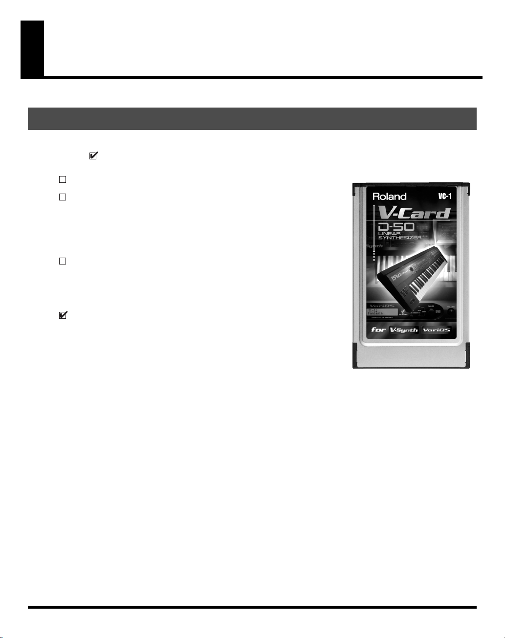
Check The Contents of The Package
This package contains the following items. When you open the package, check that no items are missing
( ). If any items are missing, please contact your dealer.
fig.00-01
VC-1
VC-1 CD-ROM
This CD-ROM contains the VC-1 recovery software and PC editor
(UniQuest VC-1).
* Please be sure to read the included license agreement before you open the
CD-ROM case.
License Agreement
This license agreement permits you to use specific software whose
copyright is owned by Roland Corporation. You must read this before
you open the CD-ROM case.
VC-1 Owner’s Manual
This is the manual you are holding. It describes how to connect the VC-1
and get it set up, guides you through its basic operation, and offers
solutions for some of the problems you may run into.
6
Page 7
Main Features
The
VC-1
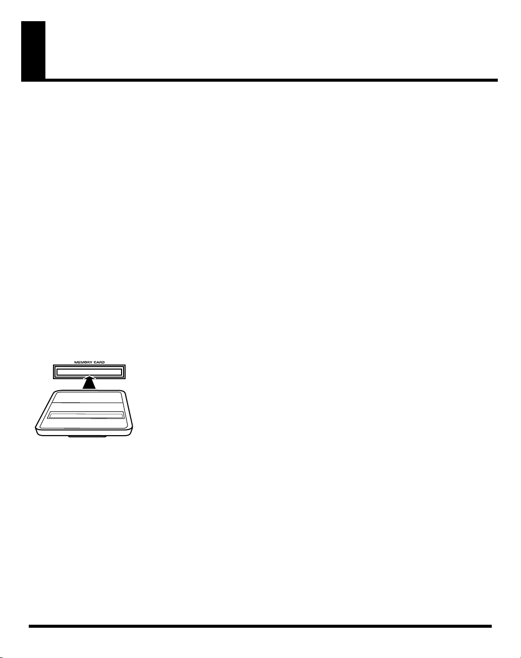
is a PC card containing the V-Synth/VariOS system program. Just insert the
CARD
slot of the V-Synth/VariOS, turn on the power, and you are ready to go. The program is
automatically loaded from the
Perfect Simulation of the D-50’s Tones!
fig.01-01
The VC-1 comes complete with all 64 of the D-50’s preset patches,
including the famous preset tones “
Native Dance
sound libraries
naturally handles
create your own original tunes exactly as you would with your
D-50. Of course, this gives you a perfect simulation of the D-50’s
tones, from the sound generator algorithms to editing of the
parameters! It even reproduces the subtle nuances obtained when
playing the instrument.
In addition, it also comes with an additional 64 new patches, which use waves (28 types) that are so large
that the original D-50 would have been technologically incapable of containing them.)
.” It also is programmed with the D-50/D-550
PN-D50-01–04
MIDI bulk dumps
VC-1
, transforming the V-Synth/VariOS into a D-50!
Fantasia
(with 256 patches). Since it
, you can use the VC-1 to
” and “
Digital
VC-1
in the
Introduction
PC
Editing and Performances That Surpass the Original!
fig.01-02
V-Synth:
VariOS:
All sound generator parameters are assignable to the
V-Synth’s full complement of editing controls.
Parameters can also be edited with the touch panel,
allowing you to almost instantly turn your creative
inspirations (no matter how fleeting) into sounds you
can use. Plus, the Time-Trip Pad (used instead of a
joystick), the D-Beam controller, the C2 assignable
control knobs, and other controls use performance
parameters capable of outputting Control Change
messages. This allows you to express your emotions
directly as you play. Whether the fun of creating
sounds or pleasure of performing, this far outdoes the
original.
The C1, C2, and C3 knobs correspond to Tone Balance, Reverb Balance, and Portamento
Time, respectively. In addition, you can install the included
computer for complete freedom in editing a wide variety of sound module parameters, giving
you sound creation capabilities far exceeding those of the original D-50.
UniQuest VC-1
encoder in your
7
Page 8
Introduction
Pro Spec Legacy Synthesizer!
fig.01-03
Internal processing upgraded with the latest technology vastly
improves the response and dynamic range from the time you
press the keys to the moment the sounds are played. The V-Synth
or VariOS hardware is used as the means of outputting sounds,
which means it’s also compatible with digital outputs (optical/
coaxial). This gives you a
specs
good enough for the latest recording environments.
What is the digital synthesizer: D-50?
The D-50, released in 1987, was Roland’s first fully digital synthesizer. Equipped with an LA
(Linear Arithmetic Synthesis) format sound generator that combined PCM and subtractive
synthesis, it opened the door to countless new sounds for levels of creativity surpassing
anything up to that point. The D-50 is a renowned, historically significant synthesizer that
Roland, the company that laid the foundation for digital synthesizers, is proud to have
created.
The D-550, also released in 1987, shrank the D-50's powerful synthesizer engine into a mere
two rack spaces.
legacy synthesizer with professional
8
Now, more than fifteen years after it came on the scene, the D-50 continues to be used by
creative artists around the world. There are numerous sound libraries stocked with many
original patches. In the course of time, however, keyboards and buttons age and wear out. It
looked like the day would come when the D-50’s sounds would no longer be heard.
In taking up the challenge of realizing new possibilities for the synthesizer, Roland has
created a revolution in technology. At the same time, we want you to continue to using your
treasured D-50 with peace of mind. Hence, the VC-1, which transforms your V-Synth/VariOS
into a D-50, not only sweeps away any worries about your D-50 growing old, but also offers
new potential that goes beyond the original instrument.
We hope that you will discover and enjoy the unrealized potential that the D-50 still offers.
And if you have never played the D-50, you definitely need to check out its vintage sounds.
Page 9
Using with the V-Synth
Try Out the Sounds............................ 15
Turning On the Power ..........................................................15
Selecting Patches and Playing Sounds ............................... 16
Viewing Various Information .............................................. 18
Applying Effects to the Sound.......... 19
Applying an Effect by Touching to the Pad....................... 19
Applying an Effect by Passing Over the D Beam ............. 20
Assigning Parameters to the Controllers ........................... 21
How to Make the Patch Factors........................................... 26
Settings Common to All Screens ..................................26
CONTROL .......................................................................28
OUTPUT (Output Mode)............................................... 29
CHASE .............................................................................31
TONE TUNE ................................................................... 32
MIDI.................................................................................. 32
Saving Patches You’ve Created ....... 33
Naming a Patch...................................................................... 33
Saving Patches........................................................................ 34
Reset to Default Factory Settings......................................... 35
Transferring Patches To and From the D-50/550 ........ 36
Transferring Patches from the D-50 to the VC-1............... 36
Transfer the patch from the memory card to the D-50/550 .............37
Transferring Patches from the D-50/550 to the VC-1 ....................... 38
Saving Transferred Patches with the VC-1 ................. 39
Transferring Patches from the VC-1 to the D-50/550....... 40
Copying a Reverb Type ........................................................42
Overview of the VC-1 ......................... 44
Memory Structure.................................................................. 44
The Basic Concept of a Tone ................................................45
Structure of Tone Parameters............................................... 48
Creating a Patch .................................50
How to Make the Patch Settings.......................................... 50
Useful Functions for Editing ............................................... 51
Editing a Value................................................................ 51
Undoing an editing Operation...................................... 51
Editing with the Panel Controls (Partial Select)......... 52
Silencing the Sound of the Partial ................................52
Copying Tone Settings................................................... 53
Copying Parameter Settings.......................................... 54
Auditioning the Sound Before Editing........................ 55
Initializing Patch Settings .............................................. 56
Tone Parameters ................................57
Common Parameters............................................................. 57
Structure........................................................................... 57
P-ENV (Pitch Envelope)................................................. 58
LFO (Low Frequency Oscillator) .................................. 60
EQ/CHORUS (Equalizer/Chorus) .............................. 61
Partial Parameters.................................................................. 63
WG Form (WG Waveform) ........................................... 64
WG PITCH....................................................................... 66
TVF (Time Variant Filter) ..............................................68
TVA (Time Variant Amplifier) .....................................73
MOD (Modulation)......................................................... 76
Settings for the Entire VC-1...............78
How to Make the System Function Settings ...................... 78
Initializing the System Settings............................................ 82
Connecting to Your Computer via USB............ 83
Recovering the System from the CD-ROM........................ 83
Selecting the V-Synth’s USB Storage Mode ................83
Connecting the V-Synth to Your Computer via USB ........................ 84
Recovering the System................................................... 86
Canceling the USB Connection..................................... 86
Exchanging MIDI Messages with Your Computer........... 88
9
Page 10
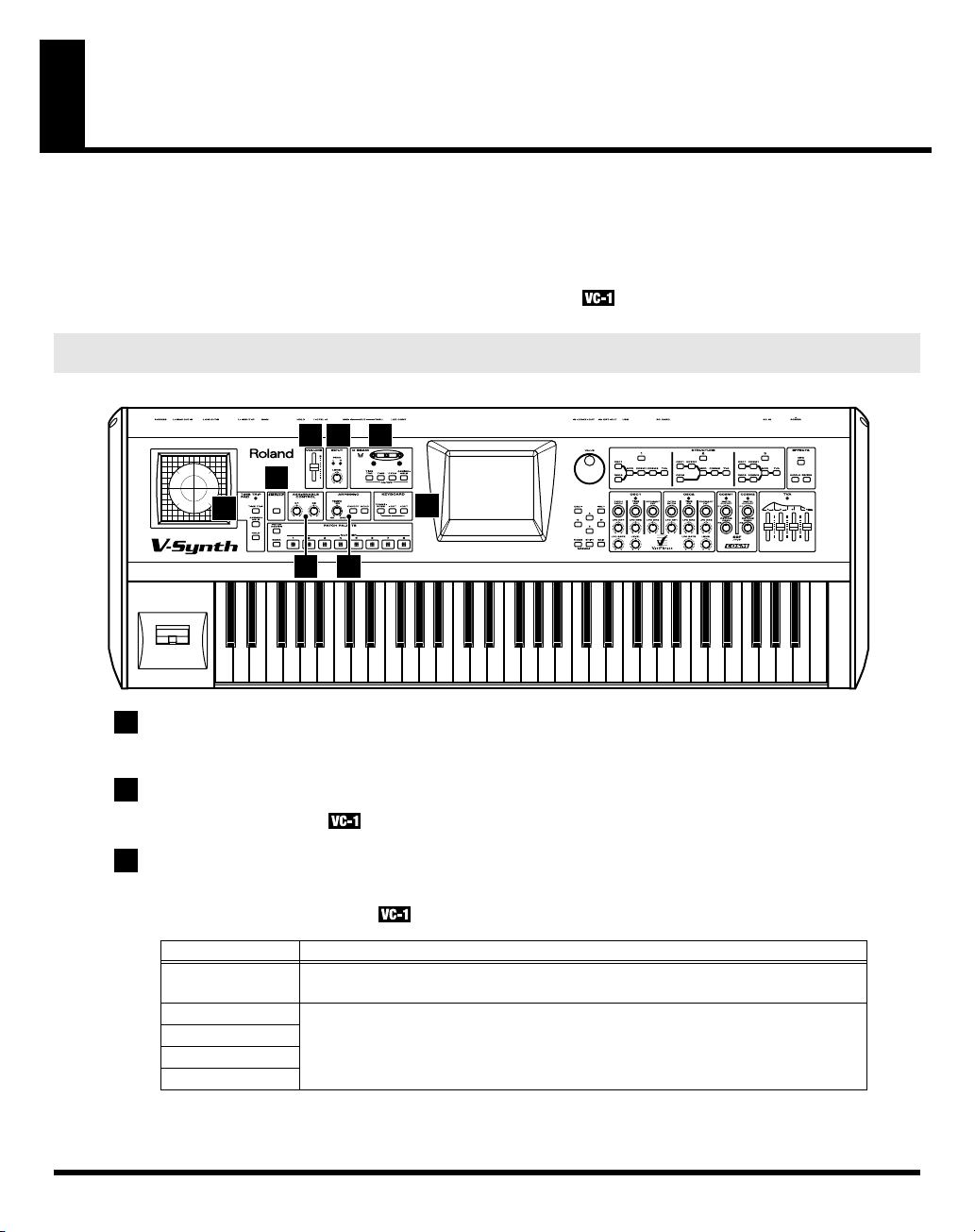
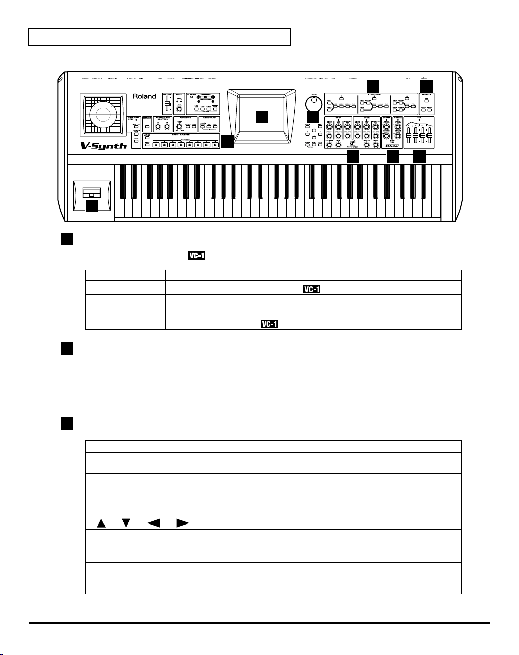
Panel Descriptions
When using the V-Synth with the
correspond to the functions ascribed to these controls on the V-Synth’s panel. Here is a description of the
names and functions in each section of the V-Synth when it is used with the VC-1. Please read this
material together with “Panel Descriptions” in the V-Synth Owner’s Manual. Controls whose functions
do not match what is shown on the panel are indicated with a mark.
Front Panel
fig.02-01(FrontPanel1–9)
1
VOLUME slider
Adjusts the overall volume that is output from the rear panel MAIN OUT jacks and PHONES jack. (p. 15)
VC-1
, the actual functions of the V-Synth’s buttons and knobs may not
1 2 3
5
4
8
6 7
10
2
INPUT
Not used with the VC-1.
3
D BEAM
You can apply a variety of effects to sounds simply by moving your hand.
* The Time Trip effect is not applied.
Display
Indicators (L, R)
[TIME TRIP]
[TIME]
[PITCH]
[ASSIGNABLE]
Function
If the D Beam controller is on, these will light when you move your hand over the
controller.
Switches the D Beam controller on/off. The effect to be controlled can be selected
by pressing the relevant button. (p. 20)
Page 11
4
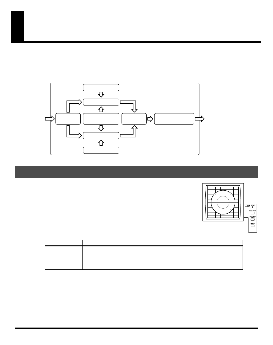
TIME TRIP PAD
By touching the pad surface with your finger you can apply a variety of effects to the sound.
* The Time Trip effect is not applied.
Panel Descriptions
Display
Indicator
[TIME TRIP]
[ASSIGNABLE]
[HOLD]
5
V-LINK
Not used with the VC-1.
6
ASSIGNABLE CONTROL
You can use them to modify the sound in realtime.
Display Function
[C1]
[C2]
7
ARPEGGIO
You can use them to modify the sound in realtime.
* The Arpeggiator is not available for use.
Display
[TEMPO]
[ON/OFF]
[HOLD]
Function
This will light when you touch the Time Trip Pad.
This switches the Time Trip Pad on and off. The effect being controlled switches
according to the buttons pressed. (p. 19)
Switches hold on/off for the effect controlled by the Time Trip pad.
Adjusts the Aftertouch Sens (p. 79).
These can be assigned a variety of D-50 different functions, allowing you to change the tone
in real time. (p. 22)
Function
Adjusts the Chase time (p. 31) or the Portamento time (p. 28).
Switches the Chase function on/off.
Switches the Portamento function on/off.
8
KEYBOARD
Here you can change the pitch range of the keyboard.
Display Function
Modifies the pitch range of the keyboard in semitone steps (-12 – +12 semitones).
[TRANSPOSE]
[-OCT], [+OCT]
* Changes you make the KEYBOARD settings are only temporary—they will be discarded as soon as the power is
turned off. If you want you keep any changes you’ve made, you must save them in the VC-1. (
System Function Settings”
Set the desired amount of transposition by holding down
pressing
Pressing
3 – +3 octaves).
[+OCT]
[+OCT]
(p. 78))
or
or
[-OCT]
.
[-OCT]
transposes the pitch of the keyboard in 1 octave units (-
[TRANSPOSE]
“How to Make the
and
11
Page 12
Panel Descriptions
fig.02-01a(FrontPanel10–17)
17
9
PATCH PALETTE
Here you can recall patches.
Display Function
[NUMBER] (1–8)
[BANK]
[PATCH ASSIGN]
These buttons let you select patches.
You can change the Patch Palette bank by holding down this button and pressing
[NUMBER] (1–8)
Not used with the VC-1.
12 13
10 11
9
14 15 16
12
10
Display
This displays information regarding the operation you are performing.
* The explanations in this manual include illustrations that depict what should typically be shown by the display.
Note, however, that your unit may incorporate a newer, enhanced version of the system (e.g., includes newer
sounds), so what you actually see in the display may not always match what appears in the manual.
11
Dial and buttons
Display
VALUE Dial
[DEC/-], [INC/+]
[ ], [ ], [ ], [ ]
[MODE]
[SHIFT]
[EXIT]
Function
This is used to modify values. If you hold down [SHIFT] as you turn
the VALUE dial, the value will change in greater increments.
This is used to modify values. If you keep on holding down one button
while pressing the other, the value change accelerates. If you press one
of these buttons while holding down [SHIFT], the value will change in
bigger increments. (p. 51)
Moves the cursor location up/down/left/right. (p. 51)
Opens the Mode Menu window.
This button is used in conjunction with other buttons to execute
various functions.
Return to the PATCH TOP screen, or close the currently open window.
In some screens, this causes the currently executing function to be
aborted.
Page 13
12
STRUCTURE
Switches the various functions on/off.
13
EFFECTS
Here you can switch the onboard effects (chorus and reverb) on/off. When an effect is on, the indicator
for its button will light.
Panel Descriptions
Display
[MFX]
[CHORUS]
[REVERB]
14
OSC1, OSC2
These can be assigned a variety of the D-50’s different functions, allowing you to change the tone in real
time. (p. 23)
15
COSM1, COSM2
These can be assigned a variety of the D-50’s different functions, allowing you to change the tone in real
time. (p. 23)
15
TVA
These can be assigned a variety of the D-50’s different functions, allowing you to change the tone in real
time. (p. 23)
17
Pitch Bend/Modulation Lever
This allows you to control pitch bend or apply vibrato.
Function
Switches chorus of the UPPER tone on and off.
Switches chorus of the LOWER tone on and off.
Switches reverb on and off.
13
Page 14
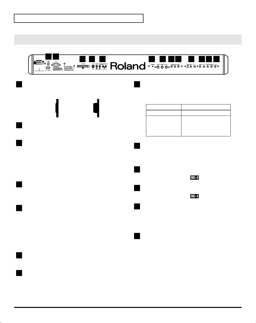
Panel Descriptions
Rear Panel
fig.02-02
1 2
1
POWER Switch
Press to turn the power on/off. (p. 15)
fig.sw-e
Power is ON
Switch is depressed.
2
AC Inlet
Connect the included power cord to this inlet.
3
PC CARD Slot
The
* Carefully insert the PC card all the way in—until it is
firmly in place.
* Never insert or pull out while the VC-1 (V-Synth) is
turned on.
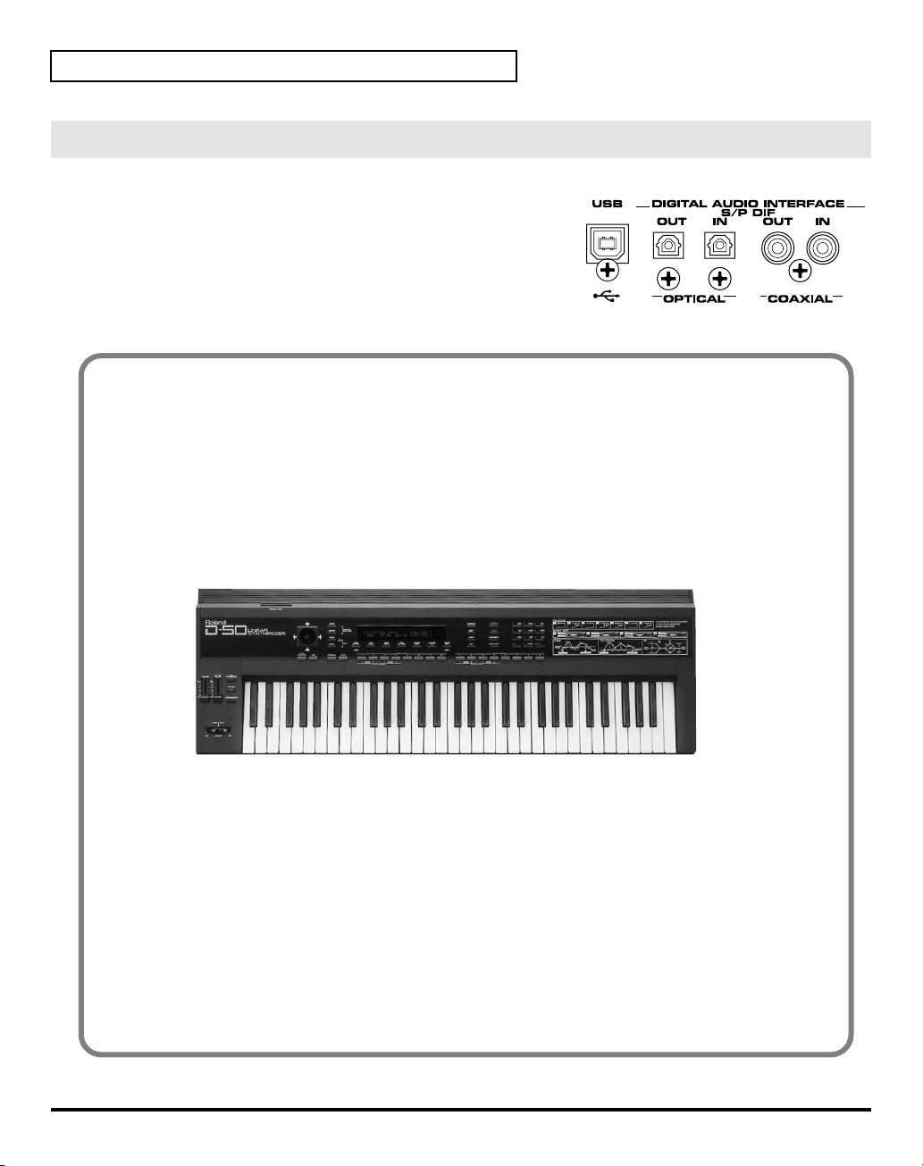
4
USB Connector
You can connect it to your personal computer to send
or receive MIDI messages. (p. 83)
When
VC-1
can be inserted here.
Switch is Releaseed..
3 4 5 6 7 8 9 10 11 12 13
Power is OFF
When
8
CTRL 1/2 PEDAL Jacks
You can connect optional expression pedals (EV-5,
BOSS FS-5U, etc.) to these jacks.
Display
CTRL 1 PEDAL
CTRL 2 PEDAL
9
HOLD PEDAL Jack
An optional pedal switch (DP series, BOSS FS-5U, etc.)
can be connected to this jack for use as a hold pedal.
10
INPUT Jacks (L, R)
Not used with the VC-1.
11
DIRECT OUT Jacks (L, R)
Not used with the VC-1.
Function
Adjusts the volume.
By assigning a desired
function to a pedal, you
can use it to select or
modify sound. (p. 23)
5
DIGITAL AUDIO INTERFACE Connector
These connectors input/output a digital audio signal
(stereo; conforming to IEC60958). The output signal is
identical to the signal that is output from the MAIN
OUT jacks.
*
IEC60958
digital audio devices.
6
LCD CONTRAST Knob
Adjusts the display contrast.
7
MIDI Connectors (IN, OUT, THRU)
These connectors can be connected to original D-50 (or
other MIDI devices) to receive and transmit MIDI
messages. (p. 83)
is a digital interface format used for consumer
14
12
MAIN OUT Jacks (L (MONO), R)
These jacks output the audio signal to the connected
mixer/amplifier system in stereo. For mono output,
use the L jack. (p. 15)
13
PHONES Jack
This is the jack for connecting headphones (sold
separately). (p. 15)
Page 15
Try Out the Sounds
Turning On the Power
To prevent malfunction and/or damage to speakers or other devices, always turn down the volume, and
turn off the power on all devices before making any connections.
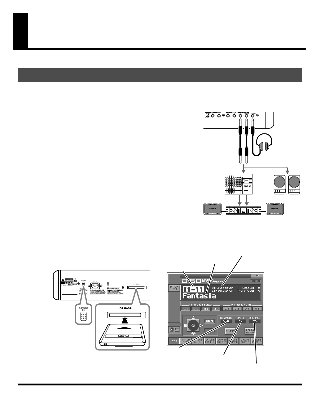
fig.03-01e(ConnectionImage)
1.
Before hooking anything up, make sure that the power on all of
your gear is turned OFF.
2.
Connect the V-Synth to your amp/speaker system.
3.
After correctly inserting the VC-1 into the PC card slot in the VSynth’s rear panel, switch ON the POWER switch.
* Carefully insert the PC card all the way in—until it is firmly in place.
* This unit is equipped with a protection circuit. A brief interval (a few
seconds) after power up is required before the unit will operate normally.
* Always make sure to have the volume level turned down before
switching on power. Even with the volume all the way down, you may
still hear some sound when the power is switched on, but this is normal,
and does not indicate a malfunction.
* Never insert or pull out while the VC-1 (V-Synth) is turned on.
4.
Turn on the power for any connected amplifiers or speakers.
5.
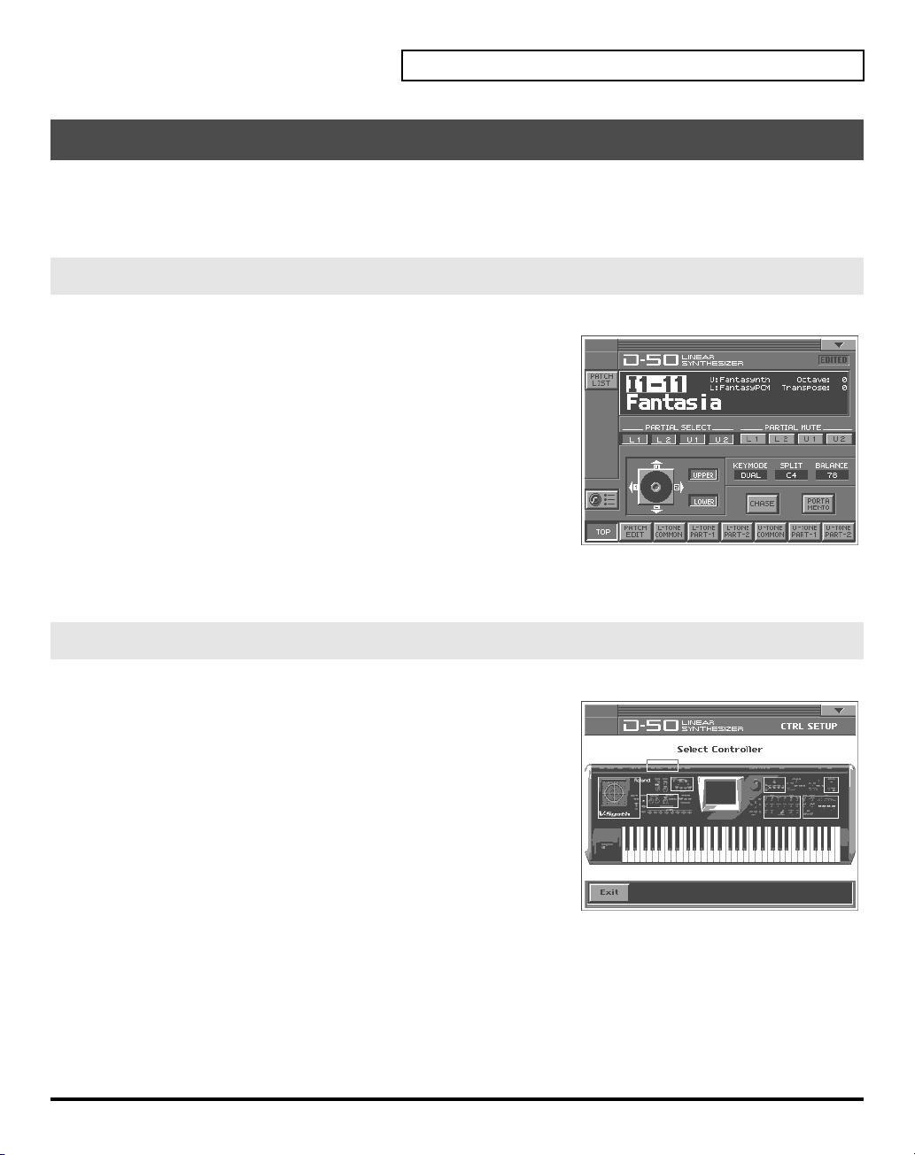
Wait for the VC-1 to start up. When it has started up normally, a screen like the following will appear. The
display shows the selected Patch.
fig.03-02e(Card&LCD_default)
Patch number
Mixer, etc.
Patch name
Power amp
Tone name
Stereo
headphones
Monitor Speakers
Key mode
Split point
The volume balance of the Upper & Lower Tone
15
Page 16
Try Out the Sounds
Selecting Patches and Playing Sounds
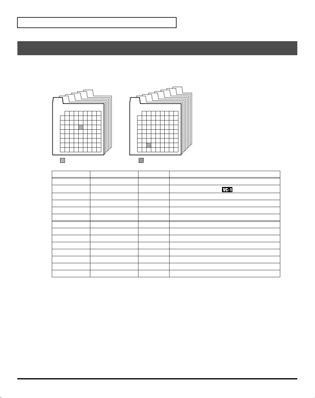
The VC-1 comes with a wide range of onboard sounds, including single tones called
A Patch is represented by a
fig.03-03e(PatchBankImage)
Patch bank (Pre1–6)
Pre6
Pre5
Pre4
Pre3
Pre2
Pre1
Number
1
2 3 4 5 6 7 8
1
2
3
Bank
4
5
6
7
8
Patch Banks
Pre1
Pre2
Pre3
Pre4
Pre5
Pre6
Int1
Int2
Int3
Int4
Int5
Int6
Int7
Int8
Included patches Overwrite Remarks
D-50
VC-1
PN-D50-01
PN-D50-02
PN-D50-03
PN-D50-04
same as Pre1
same as Pre2
same as Pre3
same as Pre4
same as Pre5
same as Pre6
(blank)
(blank)
Patch Bank
Int1
Bank
(Pre1–6, Int1–8), a
Patch bank (Int1–8)
Int5
Int4
Int3
Int2
Number
1
2 3 4 5 6 7 8
1
2
3
4
5
6
7
8
Patch No.: I1-72Patch No.: P1-34
Int6
Int7
Int8
Bank
(1–8) and a
No Original D-50 preset patches
No
Newly added patches
No D-50/D-550 sound library
No D-50/D-550 sound library
No D-50/D-550 sound library
No D-50/D-550 sound library
Yes Yes Yes Yes Yes Yes Yes Yes -
Number
patches
(1–8).
.
16
There are three ways of patch selection.
• Selecting Patches with the VALUE dial.
• Selecting Patches from the list.
• Selecting Patches with Patch Palette.
Page 17
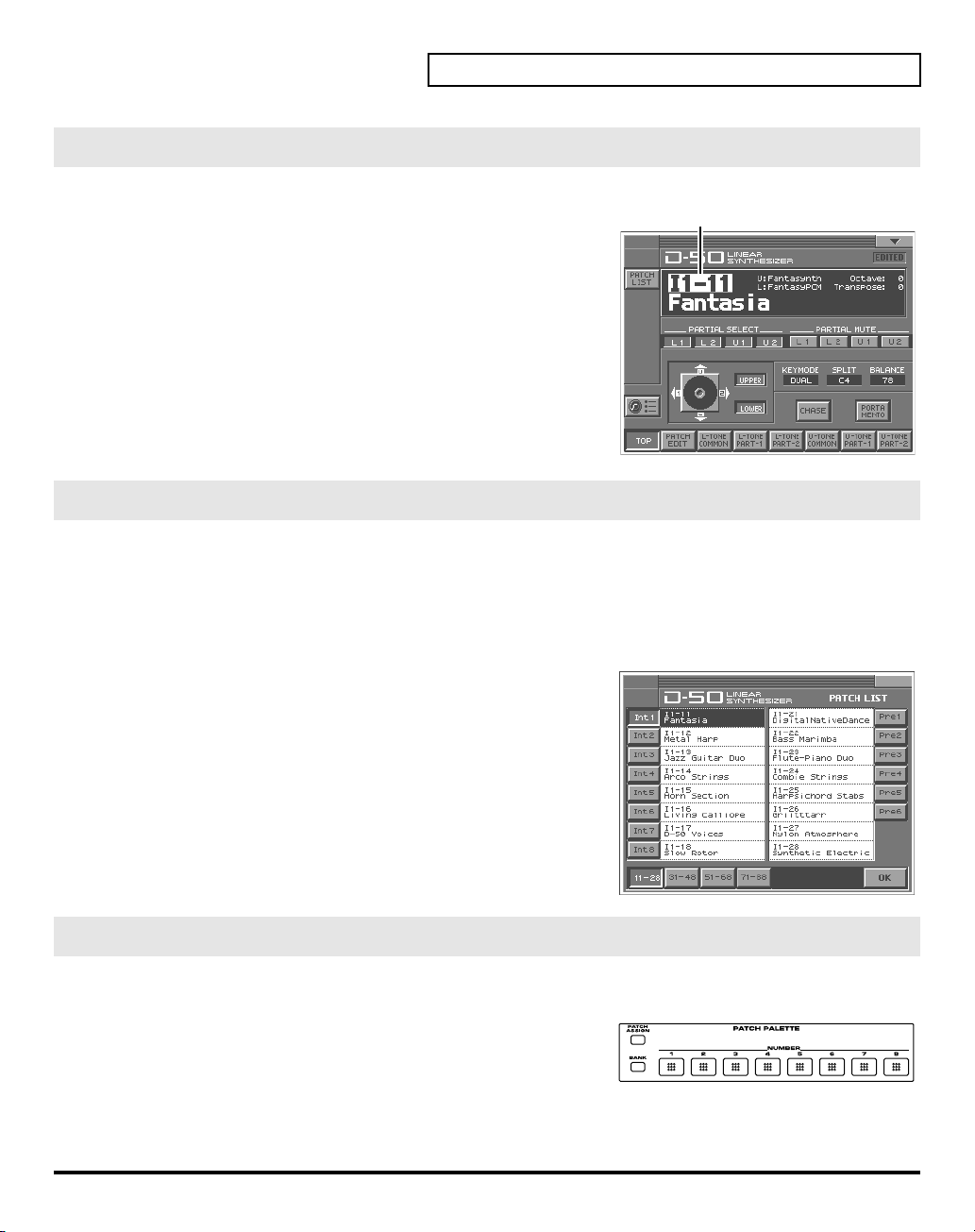
Selecting Patches with the VALUE dial
fig.03-04e(PatchNumber)
1.
Make sure the
TOP
screen—shown right—is not displayed, press
twice until the
2.
Play the keyboard to hear what the selected patch sounds like. To
change to a different patch, touch the
it, and then turn the
time you can switch more rapidly by holding down
you perform these operations.
PATCH TOP
PATCH TOP
VALUE dial
screen is displayed. If the
[EXIT]
screen appears.
Patch number
or press
[INC/+], [DEC/-]
[SHIFT]
PATCH
to highlight
Selecting Patches from the List
You can easily find the desired patch by selecting it from the patch list.
1.
Make sure the
once or twice until the
2.
Touch
fig.03-05(PatchList)
3.
Select a patch from the list. Either turn the
[INC/+], [DEC/-]
touching it on the display.
4.
To view higher-numbered patches, touch
located at bottom of the screen. To view other Patch banks, touch
<Pre1>–<Pre6>, <Int1>–<Int8>
screen.
5.
Touch
closes.
PATCH TOP
<List>
in the upper left area of the display. The
to select a patch. You can also select a patch by
<OK>
. The patch is selected and the
screen is displayed. If the
PATCH TOP
screen appears.
, located at either side of the
PATCH TOP
PATCH List
VALUE dial
<31-48>–<71-88>
PATCH LIST
or use
once or
. At this
while
,
window
Try Out the Sounds
Patch number
screen is not displayed, press
window appears.
[EXIT]
Selecting Patches with Patch Palette
You can select patches of currently selected Patch Bank instantly by simply pressing
fig.03-06
1.
Make sure the
2.
Press
NUMBER [1]–[8]
palette banks, hold down
PATCH TOP
screen is displayed.
to select a patch. To switch between patch
[BANK]
and press
NUMBER [1]–[8]
NUMBER [1]–[8]
.
.
17
Page 18
Try Out the Sounds
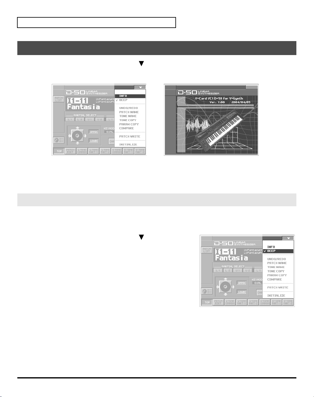
Viewing Various Information
1.
In the upper right of the screen, touch
2.
In the pulldown menu, touch
fig.08-13
3.
This window shows the following information.
Ver.:
4.
When you have finished viewing the information, press
The VC-1’s program version
<INFO>
<>
. A pulldown menu appears.
. The
Information
window appears.
[EXIT]
to close the window.
Enabling or Disabling the Beep Tone
You can specify whether or not a
screen. At the factory setting, the beep tone will be sounded.
fig.03-07
1.
In the upper right of the screen, touch
appears.
2.
In the pulldown menu, touch
With this setting, the beep tone will be heard. If you perform the
same procedure once again, the check mark will be cleared and the
beep tone will no longer be heard.
beep tone
<Beep>
will be heard when you touch a valid point on the touch
<>
. A pulldown menu
to add a check mark (✔).
18
Page 19
Applying Effects to the Sound
The performance controlling functions (we call them
by taking the following procedure.
A patch consists of several
fig.05-01e(PatchFactorImage)
Key Mode
Factors
as show below.
Tone Tune
UPPER Tone
Var iations of
Control Functions
LOWER Tone
Tone Tune
Balance
Tone
factors
in this manual) in each Patch can be edited
Output Mode
(Reverb, etc.)
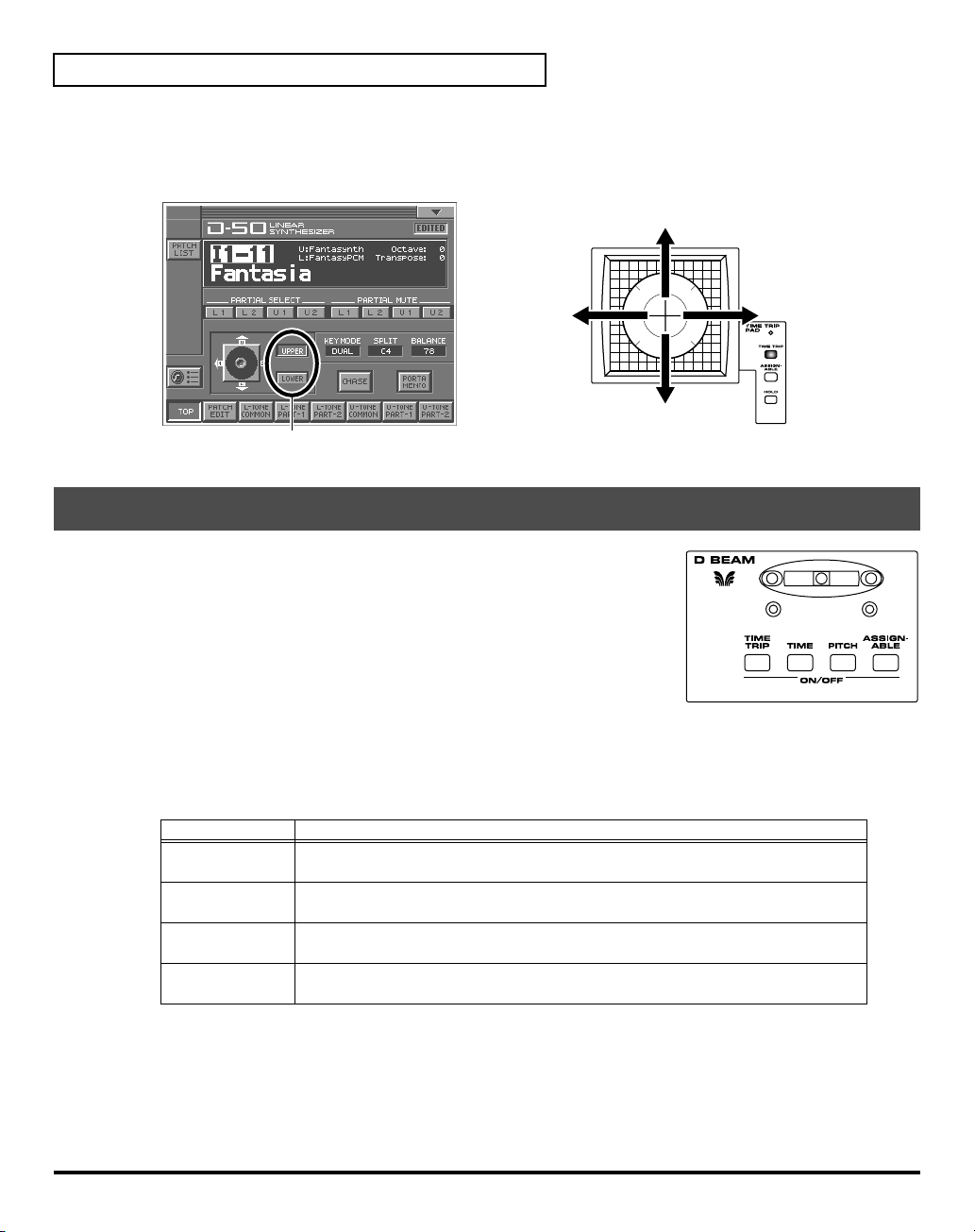
Applying an Effect by Touching to the Pad
fig.05-02(Panel_TimeTripButton)
You can apply a variety of effects by touching your fingertip to the
located at the left side of the V-Synth’s front panel. The Time Trip Pad settings are
saved with each patch. This means that you can create patches that contain Time
Trip Pad settings you like.
Time Trip pad
1.
Access the
2.
Choose the function that you want to control from the Time Trip pad, and press
the
Button
[TIME TRIP]
[ASSIGNABLE]
[HOLD]
3.
While you play the keyboard to produce sound, place your fingertip on the Time Trip pad and move your
finger in the following way.
If [TIME TRIP] is on
Using the
• Volume balance of the two Partial sounds of either Tone ; Upper or Lower.
• Volume balance of the Upper and the Lower tones.
PATCH TOP
TIME TRIP PAD
Time Trip Pad
Screen.
button for that function.
Functions
This provides the same effect as the D-50’s joystick (tone balance or partial balance).
Apply the effect that is specified by each patch. (CTRL Setup; p. 26)
you can cause the effect to be held even after you take your finger off the Time Trip
pad.
, the following two volume balance controls can be adjusted at the same time.
19
Page 20
Applying Effects to the Sound
The tone for which the partial balance is to be controlled is selected using the
you touch the
Time Trip pad
, the volume balance changes as shown below. Changing the
Tone Select button
partial balance
creates huge changes in the tone, providing very distinctive effects.
fig.05-03e(PartialBalance)
UPPER volume increases,
LOWER volume decreases
Par tial 1 decreases
Par tial 2 increases
Tone Select button (On:pressed)
Par tial 1 increases
Par tial 2 decreases
UPPER volume decreases,
LOWER volume increases
Applying an Effect by Passing Over the D Beam
fig.05-04(Panel_DBeam)
The
D Beam controller
can be used to apply various effects, depending on the function that is
assigned to it. You can also create effects in which the sound changes
instantaneously, in a way that would not be possible by operating a knob or
the bender lever. The D Beam controller settings are saved with each patch.
This means that you can create patches that contain D Beam settings you
like.
can be used simply by waving your hand over it. It
. When
20
1.
Access the
2.
Choose the function that you want to control from the D Beam controller, and press the
PATCH TOP
Screen
D BEAM
for that function to turn on the D Beam controller.
Buttons
[TIME TRIP]
[TIME]
[PITCH]
[ASSIGNABLE]
3.
While playing the keyboard to produce sound, place your hand over the D Beam, and slowly move it up
Functions
This provides the same effect as that when, after the key is played, it is then pressed
with even greater force. (Aftertouch)
This provides the same effect as that achieved by tilting the modulation level away
from you. (Modulation)
This provides the same effect as that achieved by tilting the pitch bend level to the
left and right. (Pitch Bend)
Apply the effect that is specified by each patch. (
“How to Make the Patch Factors”
(p. 26))
and down.
4.
To turn off the D Beam controller, once again press the button that you pressed in step 2, so its indicator
goes out.
button
Page 21
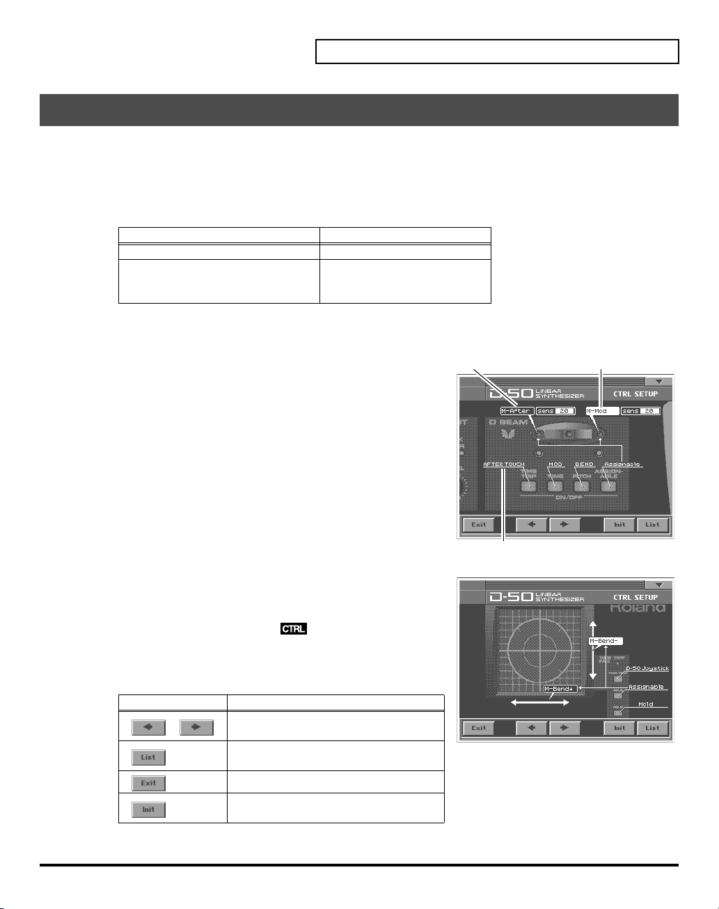
Assigning Parameters to the Controllers
You can assign a variety of patch factors (p. 133), tone parameters (p. 134), and other settings to the V-
Synth’s complement of controller sections, such as the Time Trip pad, the D Beam Controller, and the
OSC1/OSC2 sections. This is referred to as the
with the knobs and sliders and greater performance expression with the
D-50 in ways that go way beyond the original instrument.
Controllers Parameters
TIME TRIP PAD, D BEAM, C2 Knob MIDI Control Change Message
OSC1, OSC2,
COSM1, COSM2, TVA
1.
Access the
fig.05-05e
2.
Touch
SETUP
3.
Touch the Time Trip pad, D-Beam Controller, or other controller
PATCH TOP
<CTRL SET>
in the lower left of the screen. The
window appears.
Screen.
to which you want to assign the parameter. The display of that
controller section expands in the screen. The screen features at this
time function as follows.
Control Setup
. With intuitive editing of sound sources
Patch Factor (p. 133)
Tone Parameters (p. 134)
Partial Parameters (p. 135)
CTRL
Time Trip Pad
Cursor
Applying Effects to the Sound
, you can use the
Value box; Selects the parameters assigned to
the buttons and controllers.
fig.05-05a(LCD_CtrlSetupList)
4.
When editing a parameter that requires you to specify a value,
move the cursor to the value box of that parameter. Then modify
the value by either turning the
[DEC/-]
. Parameters marked by can be controlled by
VALUE dial
or pressing
specific CTRL Setup. For details on each parameter, refer to the
corresponding reference page.
The on-screen keys have the following functions.
Keys
,
Functions
Switches the set of controllers to be
enlarged in the display.
Displays the parameters to be assigned
as a list.
Returns to the CTRL SET screen.
Restores the assigned parameters to their
original factory condition.
5.
When you have finished CTRL Setup, touch
<OK>
to close the
[INC/+]
Underline; Shows the button and controller functions.
or
CTRL Setup
window.
21
Page 22
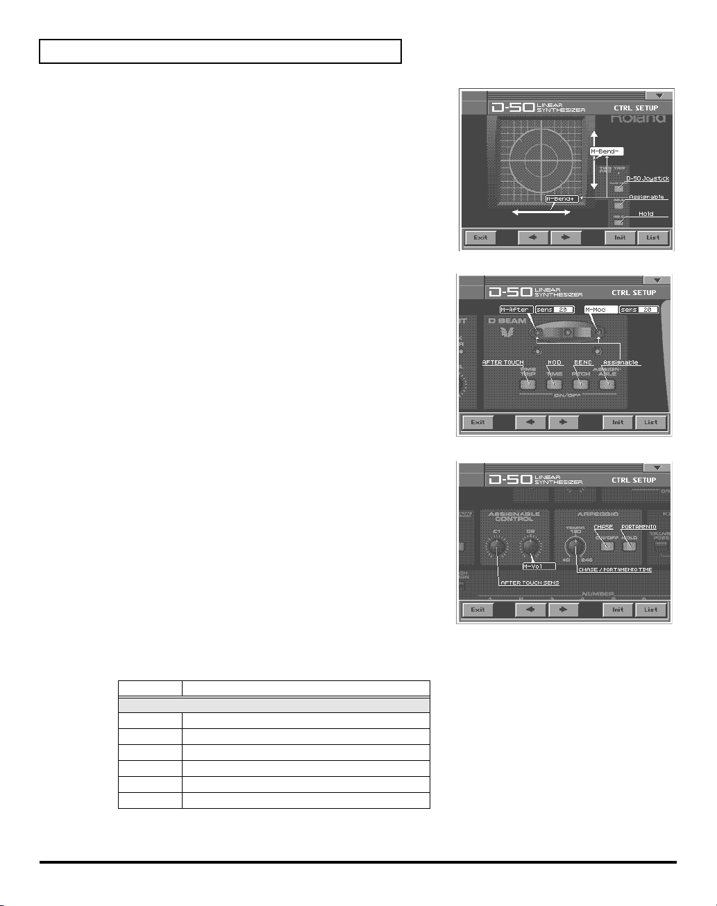
Applying Effects to the Sound
fig.05-06(LCD_CtrlSetupTTPad)
TIME TRIP PAD
ASSIGNABLE X
ASSIGNABLE Y
fig.05-07(LCD_CtrlSetupDBeam)
D BEAM
ASSIGNABLE L
ASSIGNABLE R
Sens L
Sens R
fig.05-08(LCD_CtrlSetupC1C2)
→
→
→
table 1 (p. 22)
→
table 1 (p. 22)
→
0–20
→
0–20
table 1 (p. 22)
table 1 (p. 22)
C2
C2
→
table 1 (p. 22)
table 1
You can control the following parameters.
Display
Assignable Parameter - MIDI (p. 140)
M-Mod MIDI Modulation
M-Vol MIDI Volume
M-Hold MIDI HOLD
M-After MIDI Aftertouch
M-Bend+ MIDI Pitch Bend +
M-Bend- MIDI Pitch Bend -
Parameters
22
Page 23
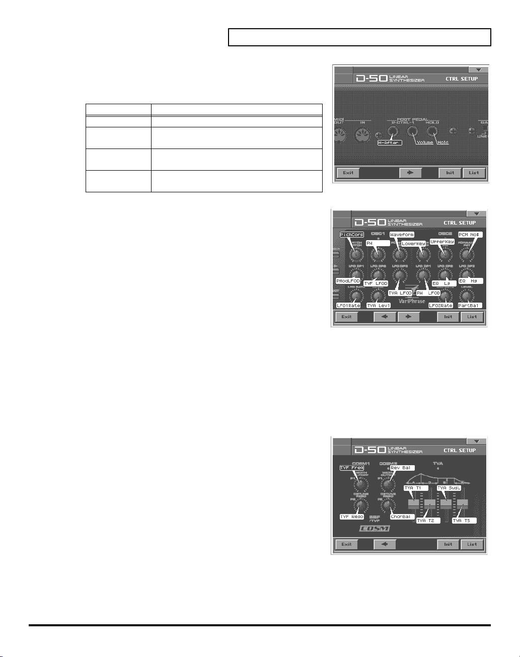
fig.05-09(LCD_CtrlSetupPedal2)
PEDAL2
PEDAL2
Display Functions
Off
ToneBal
(Tone Balance)
M-After
(Aftertouch)
M-Mod
(Modulation)
fig.05-10(LCD_CtrlSetupOsc1)
OSC1, OSC2
OSC1 PITCH
OSC1 TIME
OSC1 FORMANT
OSC1 LFO DP1
OSC1 LFO DP2
OSC1 LFO DP3
OSC1 LFO RATE
OSC1 LEVEL
OSC2 PITCH
OSC2 TIME
OSC2 FORMANT
OSC2 LFO DP1
OSC2 LFO DP2
OSC2 LFO DP3
OSC2 LFO RATE
OSC2 LEVEL
fig.05-11(LCD_CtrlSetupCosm)
→
Off, ToneBal, M-After, M-Mod
The VC-1 is NOT Controlled.
Controls the volume balance of the Upper
and the Lower Tones.
Controls the Aftertouch effect.
Controls the vibrato effect.
→
table 2 (p. 25)
→
table 2 (p. 25)
→
table 2 (p. 25)
→
table 2 (p. 25)
→
table 2 (p. 25)
→
table 2 (p. 25)
→
table 2 (p. 25)
→
table 2 (p. 25)
→
table 2 (p. 25)
→
table 2 (p. 25)
→
table 2 (p. 25)
→
table 2 (p. 25)
→
table 2 (p. 25)
→
table 2 (p. 25)
→
table 2 (p. 25)
→
table 2 (p. 25)
Applying Effects to the Sound
COSM1, COSM2
COSM1 WIDTH
COSM1 DETUNE
COSM2 WIDTH
COSM2 DETUNE
TVA Attack
TVA Decay
TVA Sustain
TVA Release
→
table 2 (p. 25)
→
table 2 (p. 25)
→
table 2 (p. 25)
→
table 2 (p. 25)
→
table 2 (p. 25)
→
table 2 (p. 25)
→
table 2 (p. 25)
→
table 2 (p. 25)
23
Page 24
Applying Effects to the Sound
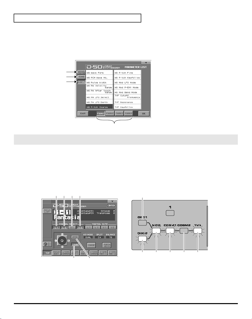
LIST (OSC1, OSC2, COSM1, COSM2 and TVA)
• Tone Parameters; The Tones (UPPER or LOWER) to be applied are specified with the
• Partial Parameters; The Partials (L1, L2, L3 or L4) to be applied are specified with the
button.
fig.05-11ae
Patch Factors
Tone Parameters
Par tial Parameters
Page
Specify the Tones or the Partials to be applied
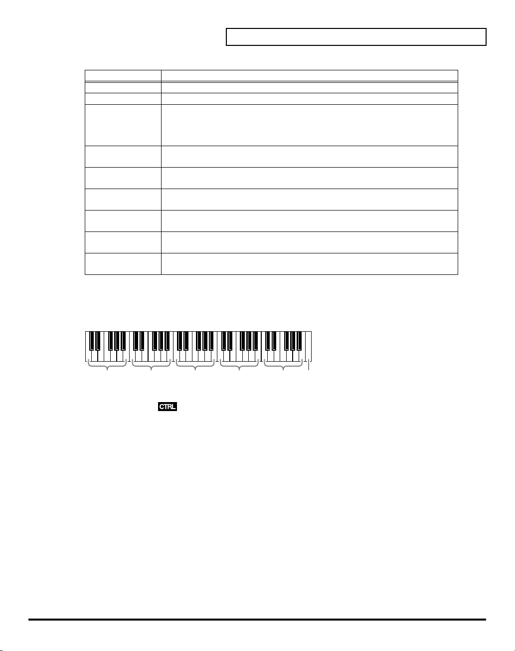
The partials to which the tone parameters assigned to the different knobs and sliders (OSC1, OSC2,
COSM1, COSM2 and TVA) are applied are specified with the
button.
• Tone Parameters; The Tones (UPPER or LOWER) to be applied are specified with the
• Partial Parameters; The Partials (L1, L2, L3 or L4) to be applied are specified with the
button.
fig.05-11be
Par tial Select
On On Off
On
UPPER
(Off)
Tone Select
Tone Select
Partial Select
button or the
Tone Select
Partial Select
button.
Partial Select
button.
24
On Off
Tone Select
LOWER
(On)
L1
(On)
L2
(On)
* The Tone Select or the Partial Select setting will be written by the Patch Write Procedure.
U1
(Off)U2(On)
Page 25
table 2
You can control the following parameters.
Display
PATCH TOP (p. 26)
ToneBal Tone Balance
PATCH EDIT CONTRL (p. 28)
BendRang Bender Range
AftrPB
PortTime Portamento Time
PortMode Portamento Mode
PATCH EDIT OUTPUT (p. 29)
Rev Bal Reverb Balance
TotalVol Total Volume
PATCH EDIT CHASE (p. 31)
ChasLevl Chase Level
ChasTime Chase Time
PATCH EDIT TONE TUNE (p. 32)
LowerKey Lower Tone Key Shift
UpperKey Upper Tone Key Shift
LowerTun Lower Tone Fine Tune
UpperTun Upper Tone Fine Tune
TONE COMMON STRUCT (p. 57)
PartBal Partial Balance
TONE COMMON P-ENV (p. 58)
PEnvVelo P-ENV Velocity Range
PEnvTKF
PEnvT1 P-ENV Time 1
PEnvT2 P-ENV Time 2
PEnvT3 P-ENV Time 3
PEnvT4 P-ENV Time 4
PEnvL0 P-ENV Level 0
PEnvL1 P-ENV Level 1
PEnvL2 P-ENV Level 2
PEnvSusL P-ENV Sustain Level
PEnvEndL P-ENV End Level
PModLFOD P-Mod LFO Depth
PModLevr P-Mod Lever
PModAftr P-Mod Aftertouch
TONE COMMON LFO (p. 60)
LFO1Wave LFO-1 Waveform
LFO1Rate LFO-1 Rate
LFO1Dely LFO-1 Delay Time
LFO1Sync LFO-1 Sync
LFO2Wave LFO-2 Waveform
LFO2Rate LFO-2 Rate
LFO2Dely LFO-2 Delay Time
LFO2Sync LFO-2 Sync
LFO3Wave LFO-3 Waveform
LFO3Rate LFO-3 Rate
Parameters
Aftertouch Bend
Range
P-ENV Time
Keyfollow
Display
LFO3Dely LFO-3 Delay Time
LFO3Sync LFO-3 Sync
TONE COMMON EQ/CHORUS (p. 61)
EQ Lg Low EQ Gain
EQ Hg High EQ Gain
ChorRate Chorus Rate
ChorDpth Chorus Depth
ChorBal Chorus Balance
TONE PARTIAL FORM (p. 64)
Waveform WG Waveform
PCM No# WG PCM Wave No.
PW WG Pulse Width
PW Velo
PW Aftr
PW LFO WG PW LFO Select
PW LFOD WG PW LFO Depth
TONE PARTIAL PITCH (p. 66)
PichCors WG Pitch Coarse
PichFine WG Pitch Fine
PichKF WG Pitch Keyfollow
PichLFO WG Mod LFO Mode
PichENV
PichBend WG Mod Bend Mode
TONE PARTIAL TVF (p. 68)
TVF Freq TVF Cutoff Frequency
TVF Reso TVF Resonance
TVF KF TVF Keyfollow
TVF BP TVF Bias Point/Dir
TVF Blvl TVF Bias Level
TVFDpth TVF ENV Depth
TVFVelo
TVF DKF
TVF TKF
TVF T1 TVF ENV Time 1
TVF T2 TVF ENV Time 2
TVF T3 TVF ENV Time 3
TVF T4 TVF ENV Time 4
TVF T5 TVF ENV Time 5
TVF L1 TVF ENV Level 1
TVF L2 TVF ENV Level 2
TVF L3 TVF ENV Level 3
TVF SusL
TVF EndL TVF ENV End Level
Parameters
WG PW Velocity
Range
WG PW Aftertouch
Range
WG Mod P-ENV
Mode
TVF ENV Velocity
Range
TVF ENV Depth
Keyfollow
TVF ENV Time
Keyfollow
TVF ENV Sustain
Level
Applying Effects to the Sound
Display
TONE PARTIAL TVA (p. 73)
TVA Levl TVA Level
TVA Velo TVA Velocity Range
TVA BP TVA Bias Point/Dir
TVA Blvl TVA Bias Level
TVA Velo
TVA TKF
TVA T1 TVA ENV Time 1
TVA T2 TVA ENV Time 2
TVA T3 TVA ENV Time 3
TVA T4 TVA ENV Time 4
TVA T5 TVA ENV Time 5
TVA L1 TVA ENV Level 1
TVA L2 TVA ENV Level 2
TVA L3 TVA ENV Level 3
TVA SusL
TVA EndL TVA ENV End Level
TONE PARTIAL MOD (p. 76)
TVF LFO TVF Mod LFO Select
TVF LFOD TVF Mod LFO Depth
TVF Aftr
TVA LFO TVA Mod LFO Select
TVA LFOD TVA Mod LFO Depth
TVA Aftr
Parameters
TVA ENV Velocity
Folw
TVA ENV Time
Keyfollow
TVA ENV Sustain
Level
TVF Mod Aftertouch
Range
TVA Mod Aftertouch
Range
25
Page 26

Applying Effects to the Sound
How to Make the Patch Factors
The Display shows several Factors at a time. If necessary, Scroll up or down the Display to find the Factor
to be edited. (Patch Parameters; p. 26)
fig.05-12(LCD_PatchEditControl)
1.
Access the
2.
Touch
3.
Touch one of the tabs in the left of the screen to select the desired
editing screen.
<CONTRL>:
<OUTPUT>:
<CHASE>:
<TONE TUNE>:
<MIDI>:
4.
When editing a parameter that requires you to specify a value,
move the cursor to the value box of that parameter. Then modify the value by either turning the
dial
5.
Repeat steps 3–4 to set patch factors.
6.
If you wish to save the changes you’ve made, perform the Save operation (p. 34). If you do not wish to
save changes, press
without saving, the display will indicate “
modified.
* If you turn off the power or select a different patch while the display indicates “
lost.
PATCH TOP
<PATCH EDIT>
or pressing
Screen.
at the bottom of the screen.
Control Edit, Portamento Edit (p. 28)
Output Mode (p. 29)
Chase Edit (p. 31)
Tone Tune (p. 32)
MIDI function (p. 32)
[INC/+]
or
[DEC/-]
.
[EXIT]
to return to the
PATCH TOP
EDITED
,” reminding you that the patch settings have been
screen. If you return to the
EDITED
,” your edited patch will be
PATCH TOP
VALUE
screen
Settings Common to All Screens
fig.05-13(LCD_PatchEditControl)
UPPER/LOWER (Tone Select Button)
You can select the tone to be controlled, upper tone, lower tone or
both tone, with the Time Trip Pad.
KEY MODE
Key Mode
keyboard.
Value:
SPL-LS, SEP-S
26
refers to the Upper and Lower Tones are played on the
WHOLE, DUAL, SPLIT, SEP, WHOL-S, DUAL-S, SPL-US,
Page 27
Display Description
WHOLE
DUAL
SPLIT
SEP
(Separate)
WHOL-S
(Whole Solo)
DUAL-S
(Dual Solo)
SPL-US
(Split Upper Solo)
SPL-LS
(Split Lower Solo)
SEP-S
(Separate Solo)
SPLIT
The Split Point can be changed as follows.
Value:
C2–C7
fig.05-14e
Upper Tone can be played in 16 voice polyphony
Both Upper and Lower Tones are played by each key in 8 voices polyphony.
The Split mode divides the keyboard into upper and lower sections, where two
different Tones can be played in 8 voices polyphony. That is, the VC-1 works like
two 8 voice synthesizers. The
sections) is shown next to the Key Mode indication.
This mode is effective when an external MIDI device is controlling the VC-
1.(
The Upper Tone is monophonic.
Both Upper and Lower Tones are monophonic.
The Upper Tone is monophonic, and the Lower Tone is 8 voices polyphonic.
The Lower Tone is monophonic, and the Upper Tone is 8 voices polyphonic.
This mode is effective when an external a MIDI device is controlling the VC-1.
(
“MIDI Implementation”
“MIDI Implementation”
Split Point
(p. 140))
(p. 140))
Applying Effects to the Sound
(where the keyboard is divided into two
C2–B2 C3–B3 C4–B4 C5–B5 C6–B6
(middle C)
BALANCE (Tone Balance)
The volume balance of the Upper and the Lower Tone can be change.
Value:
0–100
CHASE (Chase Button)
Switches the Chase function on and off. Touch the button once to switch the function on; touch it again to
switch the function off again.
Value:
OFF, ON
PORTAMENTO (Portamento Button)
Switches the Portamento function on and off. Portamento is a slide from one pitch to another, and is often
used for violin performance. Touch the button once to switch the function on; touch it again to switch the
function off again.
Value:
OFF, ON
C7
27
Page 28
Applying Effects to the Sound
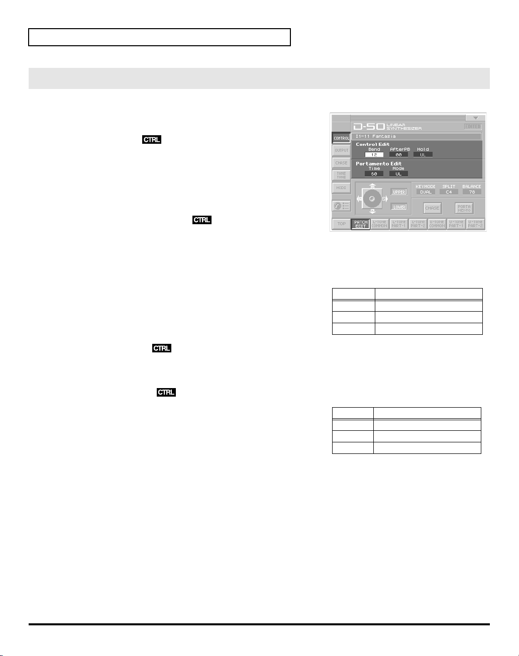
CONTROL
fig.05-15(LCD_PatchEditControl/Bend)
Patch Controls determine how the Control Functions actually
affect the Upper and the Lower Tones.
Bend (Bender Range)
This sets the variable range of the pitch change caused by moving
the Bender lever fight and left. The variable range set here may
result differently depending on the setting of the Tone Parameter
Bender Mode (p. 67).
Value:
0–12
AfterPB (Aftertouch, Pitch Bender)
This sets the sensitivity of the aftertouch effect on pitch. Higher
values mean higher sensitivity. A Minus setting decreases the pitch, and a plus setting increases it.
Value:
-12–+12
Hold (Hold Mode)
This selects the Tone that on the Pedal Hold effect. When the
mode
is
Whole
, Pedal Hold always works whichever of the above
three modes may be selected.
Value:
U, L, UL
Time (Portamento Time)
This sets the portamento time from one note to another. Higher values make the time longer.
Value:
0–100
Mode (Portamento Mode)
This selects the Tone that should take on the Portamento effect.
When the
whichever of the above three modes may be selected.
Value:
* Even when Portamento is set to ON, the Portamento ON/OFF message
sent from an external device can change the settings of Portamento.
Key Mode
U, L, UL
is
Whole
, Portamento always works
Key
Display Function
Display Function
U Works on the Upper Tone.
L Works on the Lower Tone.
UL Works on the both Tones.
U Works on the Upper Tone.
L Works on the Lower Tone.
UL Works on the both Tones.
28
Page 29
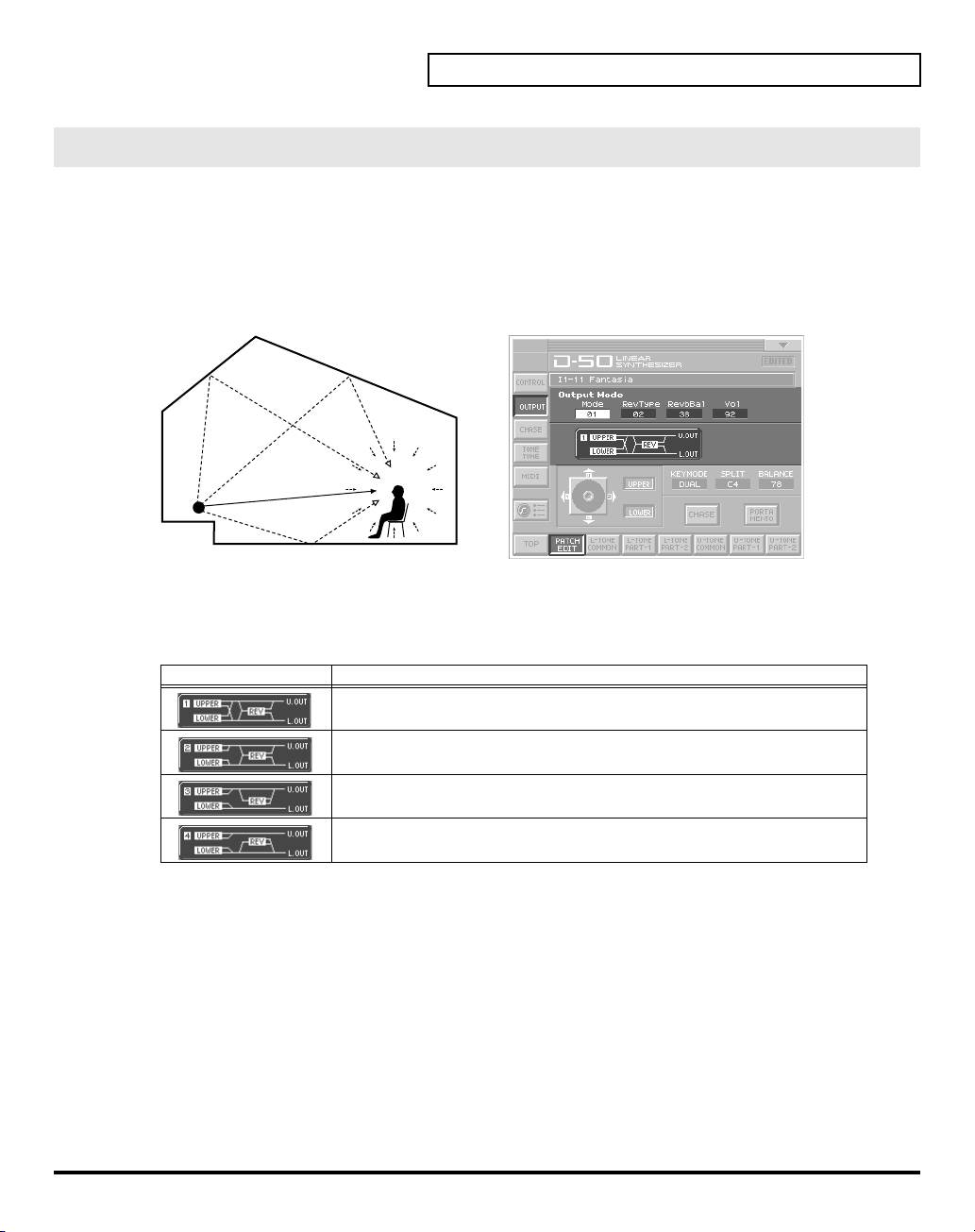
OUTPUT (Output Mode)
Applying Effects to the Sound
The Output Mode determines how the Tones take on the
outputs.
A sound reverberated in an acoustic environment consists of three parts. First, you hear the direct sound
as it travels from the source outward. Next the early reflection resounds once, or several time, from the
walls, ceiling ,and floor. Finally, you hear the reverberated sound as it reflects many times in the
environment.
fig.05-16e(LCD_PatchEditControl/Output)
Reverb Sound
Direct Sound
Sound Generator Listener
Mode (Output Mode)
Selects one of the following four output modes.
Value:
1–4
Display Function
Stereo reverb works on the mixed sound of Upper and Lower Tones, and id
sent out in stereo.
The Mixture of Upper and Lower takes on stereo reverb, and the direct sound
is sent out separately for Upper and Lower.
Only the Upper Tone takes on reverb. Upper and lower Tones are sent out
separately.
Only the Lower Tone takes on reverb, Upper and Lower Tones are sent out
separately.
reverb
effect, and how the Tones appear at the
29
Page 30

Applying Effects to the Sound
RevType (Reverb Type)
Selects one of the 32-reverb types.
Value:
1–32
Display Description Display Description
1 Small Hall 17 Bright Hall
2 Medium Hall 18 Large Cave
3 Large Hall 19 Steel Pan
4 Chapel 20 Delay (248 ms)
5 Box 21 Delay (338 ms)
6 Small Metal Room 22 Cross Delay (157 ms)
7 Small Room 23 Cross Delay (252 ms)
8 Medium Room 24 Cross Delay (274–137 ms)
9 Medium Large Room 25 Gate Reverb
10 Large Room 26 Reverse Gate (360 ms)
11 Single Delay (102 ms) 27 Reverse Gate (480 ms)
12 Cross Delay (180 ms) 28 Slap Back
13 Cross Delay (224 ms) 29 Slap Back
14 Cross Delay(148–296 ms) 30 Slap Back
15 Short Gate (200 ms) 31 Twisted Space
16 Long Gate (480 ms) 32 Space
* The reverb types 17–32 in individual banks can be used only with the patches (64 patches) contained in that bank.
Reverb types from a bank other than the internal banks (any from 1 through 32) can be copied to a reverb type in the
internal banks (any from 17 through 32).
Revbal (Reverb Balance)
Sets the volume of the reverb and direct sounds.
Value:
Vol (Total Volume)
Sets the volume of both tones, and therefore adjusts the volume difference between Patches.
Value:
30
0–100
Display
100
0–100
Function
The volume of the reverb sound = maximum, the volume of the direct sound = 0.
0
The volume of the reverb sound = 0, the volume of the direct sound = maximum.
Page 31

CHASE
Mode (Chase Mode)
• When the Key Mode is Dual
Applying Effects to the Sound
The Chase Play function makes it possible to output the Lower Tone slightly later than the Upper Tone,
which is actually played on the keyboard. This function, however, is only available in
Mode.
fig.05-17(LCD_PatchEditControl/Chase)
Sets how tones sound. Depending on the
Velocity
Value:
, the number of repeats of the delayed sound differ.
UL, ULL, ULU
Chase Level
and
Dual
or
Whole
Key
Display
UL
ULL
ULU
• When the Key Mode is Whole
Display
UL
ULL
ULU
Level (Chase Level)
Sets the volume of the chase sound.
Value:
0–100
Time (Chase Time)
Adjusts the sounding time. Higher value is longer time.
Value:
0–100
Function
The Upper Tone then the Lower Tone is played.
The Upper, then the Lower Tone is repeated.
The Upper, the Lower and the Upper Tone
alternate.
Function
The Upper Tone is played twice.
Upper Tone is repeated.
Upper Tone is repeated.
31
Page 32

Applying Effects to the Sound
TONE TUNE
The relative pitch of the Upper and the Lower Tones can be separately set. By setting slightly different
pitches, a detune effect can be obtained. Also, by lowering the pitch of the Upper Tone, and raising the
pitch of the Lower Tone, the pitches of the Two Tones can become exactly the same.
fig.05-18(LCD_PatchEditControl/Tone)
LKey (Key Shift of the Lower Tone)
Allows you to shift the pitch of the Lower Tone in semi-tone
steps.
Value:
-24–+24 (+/- 2 octave)
UKey (Key Shift of the Upper Tone)
Allows you to shift the pitch of the Upper Tone in semi-tone
steps.
Value:
-24–+24 (+/- 2 octave)
LTune (Fine Tuning of the Lower Tone)
Allows you to Tune the pitch of the Lower Tone.
Value:
-50–+50 (approx. +/- 2 cents)
UTune (Fine Tuning of the Upper Tone)
Allows you to Tune the pitch of the Upper Tone.
Value:
-50–+50 (approx. +/- 2 cents)
MIDI
You can change the setting of the MIDI Functions included Patch Factor as follows.
fig.05-19(LCD_PatchEditControl/Midi)
TxCH (Transmit Channel)
The transmit channel of each Patch can be set to a deferent
number from the basic channel. At B, the channel number is the
same as the Basic Channel.
Value:
B, 1–16
TxPC (Transmit Program Change Number)
A Program Change number to be transmitted can be set for each
patch individually. At OFF, the Program Change number
preprogrammed in each Patch is transmitted.
Value:
OFF, 1–100
TxBS (Transmit Bank Select Switch)
A Bank Select number MSB to be transmitted can be set for each patch individually (LSB = 0). At OFF, the
Bank Select number preprogrammed in each Patch is transmitted.
Value:
OFF, 0–99
SepCH (Receive Channel in Separate Mode)
A receive MIDI Channel in separate mode can be set for each Patch individually. At OFF, the receive
channel set in MIDI Functions commonly set for System Function is used. (p. 81)
Value:
OFF, 1–16
32
Page 33

Saving Patches You’ve Created
When you edit the settings of a patch, the
patch’s settings have been modified. If
you switch to another patch or turn off the power. If you want to keep a patch whose settings you have
edited, assign a name to the patch and then perform the
Naming a Patch
Before you save the patch, here’s how to give it a new name. Editing Patch or Tone names is called
Naming
•A Patch name can have up to 18 letters.
•A Tone name can have up to 10 letters.
1.
Make sure that the patch that you want to name is selected.
fig.06-01(LCD_PulldownPatchName)
2.
Touch
appears.
3.
In the pulldown menu, touch
(or
fig.06-02(LCD_PatchName&ToneName)
4.
Touch the on-screen alphabetic or numeric keys to enter the new
name in the text box. The on-screen keys have the following
functions.
.
<>
in the upper right of the screen. A pulldown menu
<TONE NAME>
). The window for naming appears.
PATCH TOP
<EDITED>
<PATCH NAME>
screen displays
is displayed, you will lose your edited patch settings if
Save operation
<EDITED>
.
to remind you that the
Keys Functions
,
* You can also move the input location cursor by pressing the
change the character at the cursor location to uppercase, and pressing
5.
When you have finished inputting, touch
Move the cursor in the text box to the desired
input location.
Turn this on when you want to input uppercase
letters or symbols.
Turn this on when you want to insert a character at the cursor location.
Erases all characters in the text box.
Deletes the character at the cursor location.
Deletes the character that precedes the cursor
location.
<OK>
to finalize the patch name.
[]
or
[]
[]
cursor buttons. Pressing
will change it to lowercase.
[]
will
33
Page 34

Saving Patches You’ve Created
Saving Patches
Changes you make to sound settings are temporary, and will be lost if you turn off the power or select
another sound. If you keep the modified sound, you must save it in the VC-1 (PATCH WRITE).
When you perform the save procedure, the data that previously occupied the save destination will be lost.
However, the factory setting data can be recovered by performing the
* Never insert or remove the VC-1 while the V-Synth is turned on. Patches cannot be saved to PC cards other than the
VC-1.
1.
Make sure that the patch you wish to save is selected.
fig.06-03(PulldownPatchWrite)
2.
Touch
<>
in the upper right of the screen. A pulldown menu
appears.
3.
In the pulldown menu, touch
WRITE
window appears.
4.
Turn the
• When you touch
appear, allowing you to rename the patch.
• By touching
patch. This can help prevent important patches from being
accidentally overwritten and lost.
VALUE dial
<ReName>
<Compare>
<PATCH WRITE>
to specify the save-destination patch.
, the
PATCH NAME
you can check the save-destination
. The
PATCH
window will
Factory Reset
. (p. 35)
34
5.
Touch
<Compare>
destination. Play the keyboard to sound the save destination patch, then check whether you really want to
overwrite it.
* The patch auditioned using the Compare function may sound slightly different than when it is played normally.
fig.06-04e(PatchWrite+PatchList)
6.
Touch
<Execute>
to turn it on. Now you can play the patch that is in the currently selected save
to execute the Save operation.
Destinanion Patch
Opens the Name Window.
Compare function
Page 35
Reset to Default Factory Settings
This restores all data in the VC-1 to the factory-set condition (Factory Reset).
If there is important data you’ve created that’s stored in the VC-1, all such data is discarded when a
Factory Reset is performed. If you want to keep the existing data, save it as describe below.
• Transmit it to an original D-50 (or an external MIDI device), and save it (p. 40).
• Transmit it to a PC using V-Synth USB function, and save it (p. 83).
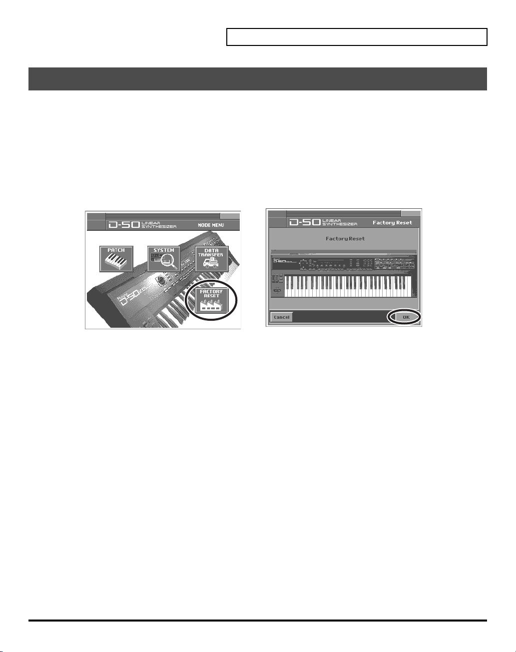
1.
Press
[MODE]
. The
2.
Touch
fig.08-11(ModeMenu)
MODE MENU
<FACTORY RESET>
window appears.
. The
Factory Reset
screen appears.
Saving Patches You’ve Created
3.
Touch
<OK>
4.
Touch
<Execute>
reset operation has been completed.
to execute the Factory Reset. When the display indicates “
Completed!
,” the factory
35
Page 36

Transferring Patches To and From the D-50/550
You can use MIDI to transmit patch data (64 patches) saved on your D-50 and receive the data with the
VC-1 (V-Synth). This procedure is known as “
own original patches (64 patches) created with the D-50 and use them with the VC-1.
Conversely, you can also send patch data edited using the VC-1 via MIDI to the D-50. This procedure is
called “
bulk dump
.”
* Read this material together with the D-50/550 Owner’s Manual.
Transferring Patches from the D-50 to the VC-1
bulk load
.” This is an easy and convenient way to take your
• Patches (64 patches) bulk loaded from the D-50 to the VC-1 are temporarily transferred to the
that includes the current patch
Currently Patch Sample
I1-11:Fantasia
I6-88:Big Wave
.
→
Destination Patch Bank Sample
→
Int1-11
–
Int1-88
→
Int6-11
–
Int6-88
patch bank
• The patches (64 patches) originally residing in the bulk load destination will appear to have been
overwritten, but actually nothing will have been lost. The patches are restored when you turn the power
off, then on again.
• The transferred patch data (64 patches) will be lost if you turn off the power. Be sure to save the data
(
“Saving Transferred Patches with the VC-1”
(p. 39)).
• Patches saved to memory cards used with the D-50/550 (M-256D) cannot be transferred directly from
these memory cards to the VC-1. First, transfer the patch data to the D-50/550 from the memory card (M-
256D), then transfer the patch data from the D-50/550 to the VC-1.
fig.04-01e
M-256D
1
2
3
Bank
4
5
6
7
8
Number
1
2 3 4 5 6 7 8
D-50
Bank
1
2
3
4
5
6
7
8
Number
1
2 3 4 5 6 7 8
VC-1:Int1
1
1
2
3
Bank
4
5
6
7
8
Number
2 3 4 5 6 7 8
36
Use the following procedure.
Transfer the patch from the memory card to the D-50/550
Transferring Patches from the D-50/550 to the VC-1
Saving Transferred Patches with the VC-1
(p. 39)
(p. 38)
(p. 37)
Page 37

Transferring Patches To and From the D-50/550
Transfer the patch from the memory card to the D-50/550
All the 64 Patches data stored on the Memory Card can be loaded to the D-50/550’s internal memory.
Using the D-50
2-1
6-1
1.
Insert the Memory Card (M-256D) into the D-50 Card Slot.
2.
Turn the
2-1.
2-2.
3.
Press the
4.
Select “
5.
Press
6.
Return the Memory Protect of the D-50 to On.
6-1.
6-2.
Memory Protect
Press the
Select “
[DATA TRANSFER]
(Card -> Int)
[ENTER]
Press the
Select “
6-2
of the D-50 to
[TUNE/FUNCTION]
Protect
” with the
button.
” with the corresponding
button. When the data transfer is completed, the display shows “
[TUNE/FUNCTION]
Protect
” with the
4 [EXIT] 3 52-2
button.
Selector button
button.
Selector button
Using the D-550
OFF
.
and turn it
Selector button
and turn it ON with the joystick.
OFF
with the joystick.
.
Complete
.”
1.
Insert the Memory Card (M-256D) into the D-550 Card Slot.
2.
3.
4.
5.
6.
Press the
Using the
Press the
Press the
Press the
[DATA TRANS]
[]
or
[]
[ENTER]
[WRITE]
[ENTER]
button.
button to turn the Memory Protect
button again. When the data transfer is completed, the display shows “
button.
buttons, select “
(Card -> Int)
.”
OFF
temporarily.
4, 6 533
Complete
.”
37
Page 38

Transferring Patches To and From the D-50/550
Transferring Patches from the D-50/550 to the VC-1
* You cannot bulk load data when a patch in the Preset Banks (Pre1 – Pre6) is selected.
* The VC-1 display does not change immediately following the bulk load. This is due to the fact that the work area is
the bulk load destination (p. 44). You can confirm the outcome of the transfer by switching patches with the
dial
.
Using the D-50
6 53, 4
1.
Use a MIDI cable to connect the D-50’s
2.
Set the D-50 and V-Synth to the same MIDI channel (the basic channel; p. 80).
3.
Press the D-50’s
4.
While pressing the D-50’s
5.
Press the D-50’s
display shows “
6.
Press the
[DATA TRANSFER]
[DATA TRANSFER]
[ENTER]
Complete
[EXIT]
button on the D-50 to return to the play mode.
button to begin the bulk dump. When the data transfer is completed, the D-50’s
.”
MIDI OUT
button.
connector to the V-Synth’s
button, specify “
B.Dump
MIDI IN
” with the
VALUE
connector.
Selector button
.
Using the D-550
1.
Use a MIDI cable to connect the D-550’s
2.
Set the D-550 and V-Synth to the same MIDI channel (the basic channel; p. 80).
3.
Press the D-550’s
4.
Select “
5.
Hold down the
When the data transfer is completed, the D-550’s display shows “
6.
Press the
38
(B.Dump)
[EXIT]
4
MIDI OUT
[DATA TRANS]
” with the D-550’s
[DATA TRANS]
button on the D-550 to return to the play mode.
button.
[]
button and press the D-550’s
connector to the V-Synth’s
or
[]
buttons.
5 3, 56
[ENTER]
Complete
MIDI IN
connector.
button to begin the bulk dump.
.”
Page 39

Saving Transferred Patches with the VC-1
The transferred patch data (64 patches) will be lost if you turn off the power. Be sure to save the data.
fig.04-04(LCD_ModeMenu_DataTrans)
1.
Press
[MODE]
on the VC-1. The
2.
Touch
<DATA TRANSFER>
appears.
fig.04-04a(LCD_DataTrans_BankSave)
3.
Touch
<Bank Copy>
screen appears.
4.
When editing a parameter that requires you to specify a value,
move the cursor to the value box of that parameter. Then modify
the value by either turning the
[DEC/-]
.
Source Bank
Selects the save-source bank.
Value:
P1 – P6, I1 – I8
Destination Bank
Selects the save-destination bank.
Value:
I1 – I8
in the left of the screen. The
MODE MENU
. The
DATA TRANSFER
VALUE dial
window appears.
screen
Bank Copy
or pressing
[INC/+]
Transferring Patches To and From the D-50/550
or
5.
Touch
<OK>
to execute the Save operation. If you want to cancel without executing, touch
<Cancel>
.
39
Page 40

Transferring Patches To and From the D-50/550
Transferring Patches from the VC-1 to the D-50/550
Using the D-50
123-1 4-34-1, 4-23-2
1.
Use a MIDI cable to connect the V-Synth’s
2.
Set the D-50 and V-Synth to the same MIDI channel (the basic channel; p. 80).
3.
Turn the
3-1.
3-2.
4.
Enable reception of bulk load data on the D-50.
4-1.
4-2.
4-3.
fig.04-05a
5.
Turn the
5-1.
5-2.
5-3.
6.
Press
7.
Touch
appears.
Memory Protect
Press the
Select “
Press the D-50’s
While pressing the D-50’s
button
Press the D-50’s
Press
Touch
Select “
dial
[MODE]
<DATA TRANSFER>
[TUNE/FUNCTION]
Protect
.
Exclusive Sw
[MODE]
<SYSTEM>
Exclusive Sw
to specify On.
on the V-Synth. The
of the D-50 to
” with the
[DATA TRANSFER]
ENTER]
of the V-Synth to On.
.
.
Selector button
button.
,” then turn the V-Synth’s
. The
MIDI OUT
OFF
.
button.
and turn it
button.
[DATA TRANSFER]
MODE MENU
DATA TRANSFER
window appears.
connector to the D-50’s
OFF
with the joystick.
button, specify
VALUE
screen
(B.Load)
MIDI IN
with the
connector.
Selector
40
fig.04-06(LCD_DataTrans_BulkDump)
8.
Touch
<B.Dump>
screen appears.
9.
Modify the value by either turning the
[INC/+]
or
Source Bank
Selects the Patch Bank in the VC-1 with the patch data to transfer
to the D-50.
Value:
I1 – I8, P1 – P6
10.
Touch
<OK>
executing, touch
11.
When the data transfer is completed, the D-50’s display shows “
12.
Press the
[EXIT]
in the left of the screen. The
[DEC/-]
.
. The bulk dump starts. If you want to cancel without
<Cancel>
button on the D-50 to return to the play mode.
.
MIDI Bulk Dump
VALUE dial
or pressing
Complete
.”
Page 41

Using the D-550
Transferring Patches To and From the D-50/550
3-2 4-1
3-2
4-2
1.
Use a MIDI cable to connect the VariOS’s
2.
Set the D-550 and V-Synth to the same MIDI channel (the basic channel; p. 80).
3.
Turn the
3-1.
3-2.
4.
Enable reception of bulk load data on the D-550.
4-1.
4-2.
4-3.
fig.04-05a
5.
Turn the
5-1.
5-2.
5-3.
6.
Press
7.
Touch
Memory Protect
Press the D-550’s
Select “
Protect
” with the
Press the D-550’s
Select “
(B.Load)
while holding the
Press the
Press
Touch
Select “
dial
[MODE]
[ENTER]
Exclusive Sw
[MODE]
.
<SYSTEM>
Exclusive Sw
to specify On.
on the V-Synth. The
of the V-Synth to On.
<DATA TRANSFER>
of the D-550 to
[TUNE]
[DATA TRANS]
” with the D-550’s
[DATA TRANS]
button again.
.
,” then turn the V-Synth’s
. The
MIDI OUT
OFF
.
button.
[]
or
[]
button.
[]
button.
MODE MENU
window appears.
DATA TRANSFER
connector to the D-550’s
buttons, and turn it
or
[]
VALUE
screen
appears.
fig.04-06(LCD_DataTrans_BulkDump)
8.
Touch
<B.Dump>
in the left of the screen. The
MIDI Bulk Dump
screen appears.
9.
Modify the value by either turning the
[INC/+]
or
[DEC/-]
.
VALUE dial
or pressing
Source Bank
Selects the Patch Bank in the VC-1 with the patch data to transfer
to the D-50.
Value:
I1 – I8, P1 – P6
4-2
3-1
4-3
MIDI IN
OFF
with the
buttons, then press the
4-2
connector.
[VALUE]
[ENTER]
.
button
10.
Touch
executing, touch
<OK>
. The bulk dump starts. If you want to cancel without
<Cancel>
.
41
Page 42

Transferring Patches To and From the D-50/550
11.
When the data transfer is completed, the D-50’s display shows “
12.
Press the
[EXIT]
button on the D-50 to return to the play mode.
Copying a Reverb Type
Complete
.”
In addition to the patches (64 patches),
(Pre 1–6, Int 1–8). Different reverb types
16 reverb types (17–32
17–32
are saved to each patch bank. The reverb types you can
use vary with the selected patch as described below.
fig.04-06ae(ReverbTypeImage)
• All shared common reverb types (1–16) can be used.
• The reverb types
17–32
in individual banks can be used only
with the patches (64 patches) contained in that bank.
• Reverb types from a bank other than the internal banks (any
from 1 through 32) can be copied to a reverb type in the internal
banks (any from 17 through 32).
• This is convenient when, for example, you want to use Reverb
Type 25 (Gate Reverb) from the Patch Bank
Type 30 in the Patch Bank
Int 1
.
Pre 1
as Reverb
* Reverb Types (17–32) are transferred simultaneously with patch data
when patch data is transferred from the D-50 to the VC-1 (bulk loaded)
or from the VC-1 to the D-50 (bulk dumped).
fig.04-04(LCD_ModeMenu_DataTrans)
1.
Press
[MODE]
2.
Touch
<DATA TRANSFER>
on the VC-1. The
MODE MENU
. The
DATA TRANSFER
window appears.
screen
appears.
are also saved to the VC-1’s patch banks
Common
Reverb Type
(NOT rewritable)
1 2 3 4
5 6 7 8
9 10 11 12
13 14 15 16
Internal BankPreset Bank
Pre1
Reverb Type
(NOT rewritable)
17 18 19 20
21 22 23 24
25 26 27 28
29 30 31 32
Int1
Reverb Type
(rewritable)
17 18 19 20
21 22 23 24
25 26 27 28
29 30 31 32
42
Page 43

fig.04-07(LCD_DataTrans_ReverbCopy)
3.
Touch
<REVERB COPY>
COPY
screen appears.
4.
Modify the value by either turning the
[INC/+]
or
[DEC/-]
Source Bank
Selects the source Patch Bank of Reverb Type.
Value:
P1 – P6, I1 – I8
No.
Selects the source Reverb Type.
Value:
1 – 32
Destination Bank
Selects the destination Patch Bank of Reverb Type.
Value:
I1 – I8
No.
Selects the destination Reverb Type.
Value:
17 – 32
5.
Touch
<OK>
. The display will ask “Are You Sure?”, then touch
operation. If you want to cancel without executing, touch
When the reverb copy is completed, the display shows “
in the left of the screen. The
VALUE dial
.
REVERB
or pressing
<Cancel>
Complete
Transferring Patches To and From the D-50/550
<Execute>
to execute the Reverb Copy
.
.”
43
Page 44
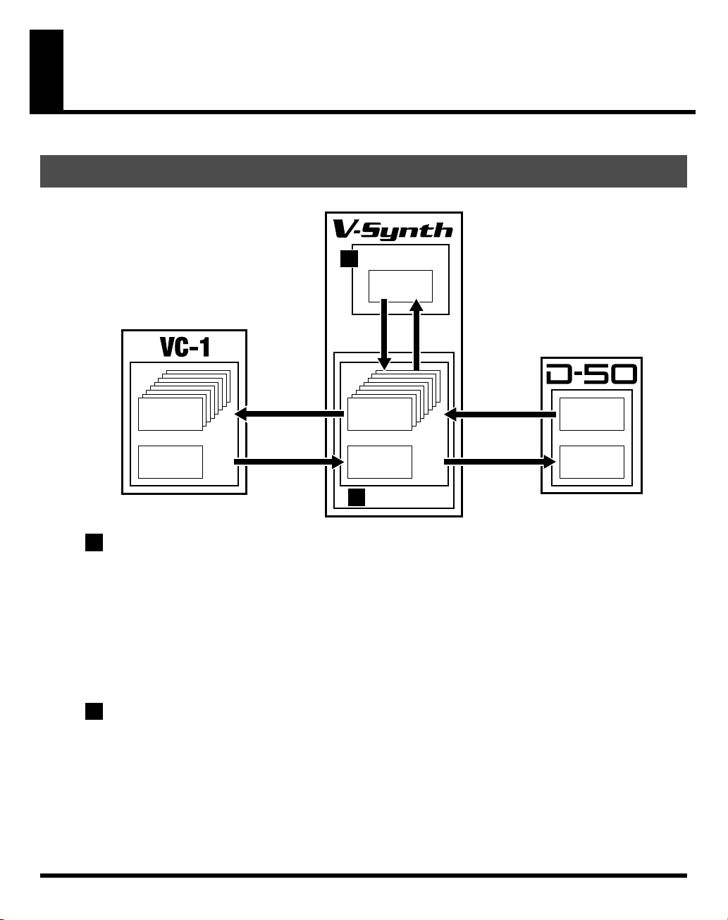
Overview of the VC-1
Memory Structure
fig.07-01(MemorySuructure)
Temporary Area
2
Patch
(1)
Patch
Write
Patch Write
Patch:Int1
(64)
Int1–Int8 (512)
Wave
(128)
1
Work Area
When the VC-1 is inserted in the V-Synth’s PC CARD slot, the system program and patch data is loaded
from the VC-1 into the V-Synth. The section where the system and patch data is loaded is called the
Area
. Content loaded to the Work Area is cleared when the V-Synth’s power is turned off. For this reason,
if you remove the VC-1 from the V-Synth and switch the power off, then on again, the V-Synth reverts to
its ordinary state.
In addition, banks (containing data for 64 patches) bulk dumped from an original D-50 (or other MIDI
device) are also stored temporarily in the Work Area. Bulk dumped data is cleared if the power is simply
turned off, so be sure to save the data to the VC-1 (p. 34).
2
Temporary Area
Patch data selected for performance is further taken from the Work Area and placed in memory called the
Temporary Area
patch data is lost if the power is simply turned off, so be sure to save these to the VC-1 (p. 34).
. Editing of tones and factors is performed on patches in this Temporary Area. Edited
Bank Save
Power ON
Patch:Int1
(64)
Int1–Int8 (512)
Wave
(128)
Work Area
1
Patch
Select
Bulk Load
Bulk Dump
Patch
(64)
Wave
(100)
Work
44
Page 45

The Basic Concept of a Tone
Throughout the process of programming the D-50, the operation remains simple and logical.
You can think of the D-50 having powerful synthesizers built in. Each of these hypothetical synthesizers
could behave like a convention analog synthesizer, or a PCM sampled synthesizer. Any combination of
two synthesizers can achieve some remarkable cross-modulation effects.
fig.07-02e(Tone)
3
Tone
Overview of the VC-1
Structure
Par tial 1
1
Par tial 2
1
Partial
The VC-1 (D-50) appears to have four powerful synthesizers built in. Each of these hypothetical
synthesizer could behave like a conventional
Consequently, They are referred to as
Partials are combined in pairs to form a
could take advantage of the LA version of cross modulation.
Synthesizer sound generator
A Synthesizer sound generator works like a conventional analog type synthesizer with an oscillator, a
filter, an amplifier and two ENV’s.
fig.07-03(BlockDiagramSynth)
Filter
ENV for pitch control
DSP
3 LFO's
Equalizer
Tone Name
analog synthesizer
Partials
TONE
TVF TVAWG
, since they are far more than just a pure synthesizer. These
, A Tone could either be a mix of the two Partials, or they
Square
Common
2
Chorus
, or a
PCM sampled synthesizer
TVA
.
Pitch
Processor
Envelope
Generator
Sawtooth
Envelope
Generator
45
Page 46
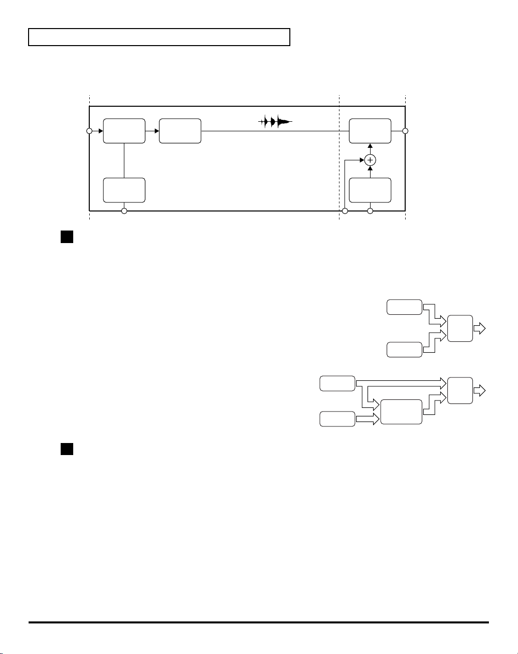
Overview of the VC-1
PCM sound generator
A PCM sound generator provides 128 different PCM sampled sounds (= waveform).
fig.07-04(BlockDiagramPCM)
PCM Wave
Memory
DSPROM
Interpolator
TVAWG
TVA
2
Structure
Structure
synthesizers (a
Pitch
Processor
, which is one of the Common Parameters, determines which two of the hypothetical
synthesizer sound generator
or a
PCM sound generator
Envelope
Generator
) are to be used as Partial 1 and
Partial 2.
fig.07-05(PertialMix)
• These two Partial sounds (Partial 1 and Partial 2) can simply be
mixed as show below. By mixing two Partials, fatter sounds can
Par tial 1
be obtained. This is effective for making strings or organ type
sounds.
Par tial 2
fig.07-06(RingModulatorBlock)
• Partial 1 can be mixed with the ring-modulated sound of
Partials 1 and 2. (
“Ring Modulator”
(p. 47))
Par tial 1
Ring
Modulator
3
Tone
A
Tone
consists of two
Partials
apply to both Partials (Partial 1 and 2) . “
(Partials 1 and 2) and a
Structure
” is one of the Common parameters. It decides which
Common
Par tial 2
block. Some Common parameters
of the two sound generators is used for each Partial. Other Common parameters are an ENV for pitch,
three LFO modules, equalizer, chorus, etc.
Mixer
Mixer
46
Page 47

Ring Modulator
The Ring Modulator multiplies two sounds, creating an unusual and metallic sound that
contains complicated harmonics. For instance, two waveforms ( and ) are
multiplied and waveform is created. This is effective for making metallic sounds.
fig.07-07(RingModulatorWave)
1
3
2
4
Patch
During live performance, you can easily select a
and Lower), together with programmed E.Q., chorus and reverberation. These other parameters are
referred to as
fig.07-08e(Patch)
4
Patch
Factor
.
Tone Tune
Patch
, which is the combination of two Tones (Upper
Overview of the VC-1
Key Mode
UPPER Tone
Var iations of
Control Functions
LOWER Tone
Tone Tune
Tone
Balance
Output Mode
(Reverb, etc.)
Patch Name
MIDI
47
Page 48

Overview of the VC-1
Structure of Tone Parameters
Depending on which
be used. Some Tone Parameters used for the Synthesizer sound generators are irrelevant to the PCM
generator. In a Structure with
those of Partial 1.
fig.07-09(ToneParam)
1
P-ENV
7
1
Pitch
Pitch
generators
Ring modulation
Waveform
2
Pulse
3
Width
PCM Wave
2
Number
are selected in the
WG TVF TVA
LFO-111LFO-2
10
WG TVA
Partial Block
, some parameters of Partial 2 are automatically set to
Partial (Synthesizer Sound Generator)
Cutoff
4
Frequency
5
TVF ENV
8
, greatly different Tone Parameters will
Level
6
Resonance
LFO-3
12
Partial (PCM Sound Generator)
9
Level
6
TVA ENV
9
TVA ENV
WG (Wave Generator)
In the WG (Wave Generator), the pitch and waveform are controlled.
1
Pitch
The basic pitch of a Partial (sound generator) can be set here. The pitch is a Common parameter, and is
therefore controlled by
2
Waveform, PCM Wave Number
This selects the waveform of the sound source. When a synthesizer sound generator is selected, the
waveform can be controlled by the
3
Pulse Width
This changes the waveform of the sound source. The pulse width is controlled by any
parameter).
48
P-ENV
and
Pulse Width
LFO-1
.
controls.
LFO
(= Common
Page 49
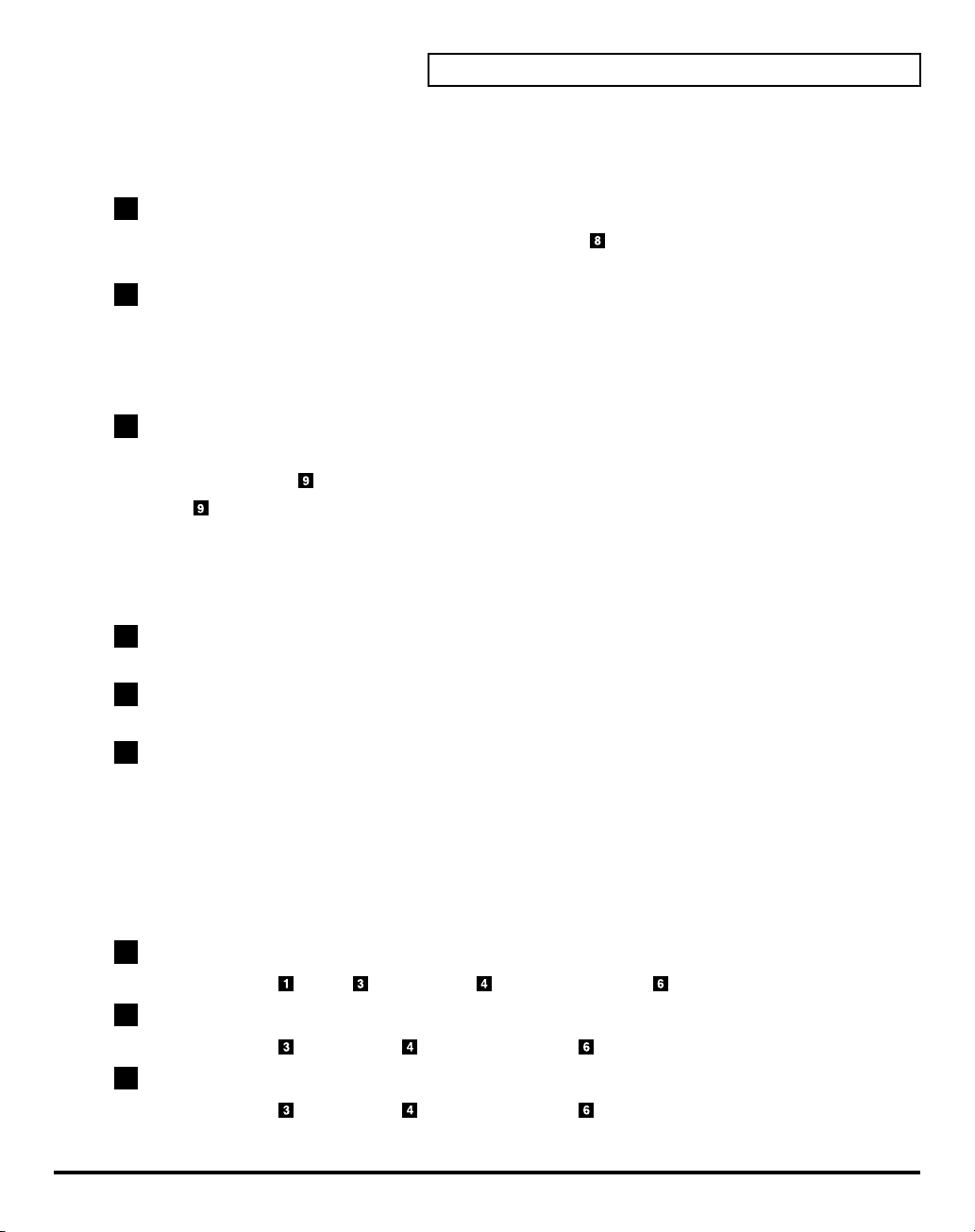
TVF (Time Variant Filter)
This fitter passes lower frequency harmonics and cuts off the higher ones. By changing the cutoff point
and the resonance, the waveform changes.
4
Cutoff Frequency
This sets the cutoff point. The cutoff point can be controlled by
parameter).
5
Resonance
This emphasizes the cut off point, making more unusual or electronic sounds.
TVF ENV
and any
TVA (Time Variant Amplifier)
This controls the volume of the Partial.
6
Level
This determines the volume of the sound. When a synthesizer sound generators used, the level can be
controlled with the
the
TVA ENV
TVF ENV
controls the level.
and
LFO
(Common Parameter) . When a PCM sound generator is used,
ENV (Envelope Generator)
This generators a control signal (envelope curve) which controls the pitch, timbre and volume of each
Partial (sound generator).
Overview of the VC-1
LFO
(= Common
7
P-ENV
This is the ENV which controls pitch. It can be set for two selected Partial at once.
8
TVF ENV
This ENV controls the cutoff point, and can be set for each Partial separately.
9
TVA ENV
This ENV controls the volume level. This is can be set for each Partial separately.
LFO (Low Frequency)
This oscillator generates low frequencies only.
Any of the three LFO’s can be used for the two partials, Vibrato, PWM growl or tremolo effects can be
obtained using these LFO’s
*A different LFO can be used for each section or a
10
LFO-1
This can control
11
LFO-2
This can control
12
LFO-3
This can control
Pitch, Pulse Width, Cutoff Frequency
Pulse Width, Cutoff Frequency
Pulse Width, Cutoff Frequency
Partial Parameters
or
or
.
Level
Level
or
Level
.
.
.
49
Page 50

Creating a Patch
With the VC-1, you have total control over a wide variety of settings. Each item that can be set is known
as a “
parameter
“
editing
parameters.
There are two methods of sound creation.
• Editing an existing sound.
• Initializing all the parameters of a certain Partial, and then editing the Partial. (p. 56)
* Changes you make to sound settings are temporary, and will be lost if you turn off the power or select another sound.
If you want to keep the modified sound, you must save it. (
How to Make the Patch Settings
A number of patch
fig.08-01e(PatchTop)
1.
Access the
settings you wish to modify (p. 16).
* If you want to create all your patches from the ground up, rather than the
patches that have already been prepared, carry out the Initialize
operation (p. 56).
2.
The parameters are organized into several editing groups. Touch
one of the buttons at the bottom of the screen to select the edit
group containing the parameters you want to set.
.” When you change the values of parameters, you are doing what is referred to as
.” This chapter explains the procedures used in creating patches, and the functions of the patch
“Saving Patches”
Factors
and
PATCH TOP
Tone Parameters
screen, and select the patch whose
are shown in each window.
(p. 34))
50
fig.08-02(L-ToneCommonP-ENV)
3.
Touch one of the tabs in the left of the screen to select the desired
editing screen.
4.
When editing a parameter that requires you to specify a value,
move the cursor to the value box of that parameter. Then modify
the value by either turning the
[DEC/-]
. You can also modify a value by dragging over the touch
screen.
5.
Repeat steps 2–4 to complete a patch.
6.
If you wish to save the changes you’ve made, perform the Save
operation (p. 34). If you do not wish to save changes, press
to return to the
* If you return to the
the patch settings have been modified. If you turn off the power or select a different patch while the display indicates
“
EDITED
PATCH TOP
PATCH TOP
,” your edited patch will be lost.
VALUE dial
screen.
screen without saving, the display will indicate “
or pressing
[INC/+]
[EXIT]
or
Patch factor
Lower Tone
EDITED
,” reminding you that
Upper Tone
Page 51

Useful Functions for Editing
The VC-1 provides numerous ways in which you can edit your own patches more conveniently.
Editing a Value
Creating a Patch
To edit a value, you can use the
value using the cursor as described earlier, and modify its value. Each parameter has its own range of
possible values. You
maximum value.
fig.08-03(ValueDial,etc)
Cursor Buttons
Press
[], [], []
VALUE dial
• Turning the
decreases its value.
• Hold down
large value changes more quickly.
[INC/+] and [DEC/-]
• Press
• Keep the button pressed for continuous adjustment.
• For faster value increases, keep
values quickly, keep
• Hold down
[SHIFT]
[INC/+]
[SHIFT]
CANNOT
VALUE dial
as you move the
to increase the selected value, and
[DEC/-]
while using
VALUE dial, [INC/+]
set any value smaller than the minimum value or greater than the
, or
[]
(the cursor buttons) to move the cursor.
clockwise increases the value, and turning it counterclockwise
VALUE dial
[INC/+]
pressed down and press
[INC/+]
Undoing an editing Operation
The
Undo
function returns the current value of the parameter to the original value before being edited.
This only refers to the last parameter that has been adjusted.
fig.08-04(LCD_pulldown_undo)
or
[DEC/-]
to increase value increments to make
[DEC/-]
to decrease it.
pressed down and press
[INC/+]
.
or
[DEC/-]
, the value will change in larger steps.
.In each VC-1 screen, you can select a
[DEC/-]
. To decrease
1.
In the upper right of the screen, touch
appears.
2.
In the pulldown menu, touch
<UNDO>
<>
. A pulldown menu
.
51
Page 52

Creating a Patch
Editing with the Panel Controls (Partial Select)
You can assign a variety of parameters (such as TVF Resonance or TVA Level) to the knobs and sliders at
the right of the front panel for direct, intuitive editing of the parameters.
The partials to which the tone parameters assigned to the different knobs and sliders are applied are
specified in the
the knobs and sliders to edit the tone parameters of the partial whose indicator is lit.
fig.08-07(LCD_PartialSelect & PANEL_Strycture1Button)
PATCH TOP
screen or with
STRUCTURE [1]
at the right of the front panel. You can use
Off Off On Off
* The Partial select setting will be written into the VC-1 by taking the saving procedure. (p. 34)
Silencing the Sound of the Partial
While editing a Partial parameter, any Partial sound can be muted (Partial Mute).
Partials to be muted are specified in the
front panel. The partial is muted when the indicator is off; muting is defeated when the indicator is lit.
fig.08-08(LCD_PartialMute & PANEL_Structure3Button)
* The Partial Mute setting will be written into the VC-1 by taking the saving procedure. (p. 34)
PATCH TOP
OnOffOffOff
L1
(Off)
screen or with
U1
(Off)U2(On)
L1
(Off)L2(Off)
U1
L2
(On)U2(Off)
(Off)
STRUCTURE [3]
at the right of the
52
Page 53

Copying Tone Settings
A Tone from another Patch can be copied to the patch currently selected (Tone Copy).
fig.08-05(LCD_Pulldown_ToneCopy)
1.
Make sure the
2.
Touch
appears.
3.
In the pulldown menu, touch
window appears.
fig.08-06(LCD_ToneCopyWindow)
4.
Touch some buttons (checkbox) in the left side of the screen to
select the object you want to copy (✔).
Display Value
5.
Touch a button (valuebox) in the right side of the screen to select
the destination Tone.
PATCH TOP
<>
in the upper right of the screen. A pulldown menu
<Source>
<TONE>
<PATCH FACTOR> Off, On (✔)
<CTRL SETUP> Off, On (✔)
screen is displayed.
<TONE COPY>
I1-11–I8-88,
P1-11–P6-88
Off, On (✔),
UPPER, LOWER
. The
TONE COPY
Creating a Patch
1
2 3
Display Value
<TONE>
6.
Touch
<Execute>
<CANCEL>
.
UPPER, LOWER
to execute the copy operation. If you want to cancel without executing, touch
53
Page 54

Creating a Patch
Copying Parameter Settings
A group of Tone parameters can be copied within a Patch (Parameter Copy).
fig.08-06a(LCD_Pulldown_ParamCopy)
1.
Make sure the
2.
Touch
appears.
3.
In the pulldown menu, touch
COPY
fig.08-06b(LCD_ParamParamWindow)
4.
Touch some button (valuebox) in the left side of the screen to
select the object you want to copy.
PATCH TOP
<>
in the upper right of the screen. A pulldown menu
window appears.
screen is displayed.
<PARAM COPY>
. The
PARAM
TONE (Source Tone)
Select the Tone to be copied.
Value:
UPPER, LOWER
PARTIAL (Source Partial)
Select the Partial parameter to be copied.
Value:
ALL, COMMON, PART-1, PART-2
Display
<ALL>
<COMMON>
<PART-1>
<PART-2>
BLOCK (Source Block)
If either PART-1 or PART-2 is selected in , any of the following Blocks can be selected.
Value:
ALL, WG, TVF, TVA
Display
<ALL>
<WG>
<TVF>
<TVA>
5.
Touch some button (valuebox) in the right side of the screen to select the destination Tone.
TONE (Destination Tone)
Select the location for the Source Tone.
Value:
UPPER, LOWER
Function
All the parameters
Common parameters
Partial 1’s parameters
Partial 2’s parameters
Function
All parameters
WG parameters (p. 64)
TVF parameters (p. 68)
TVA parameters (p. 73)
1
2
3
4
5
54
Page 55

PARTIAL (Source Partial)
If PART-1 or PART-2 is selected in , select the corresponding block.
Value:
PART-1, PART-2
* When is set to
6.
Touch
<Execute>
<CANCEL>
All
or
COMMON
to execute the copy operation. If you want to cancel without executing, touch
.
, setting is ignored.
Auditioning the Sound Before Editing
Creating a Patch
While editing a parameter, you may wish to hear the original sound before it was edited. The
function allows you to call the original Patch without erasing the edited sound.
1.
In the upper right of the screen, touch
2.
In the pulldown menu, touch
fig.08-14
3.
Touch
4.
5.
Touch
Touch
<COMPARE>
<COMPARE>
<OK>
to turn it on, and the original sound may be heard by playing the keyboard.
again to turn it off, and the edited sound will come back.
to return to the
<CONPARE>
PATCH TOP
<>
. A pulldown menu appears.
. The
PATCH COMPARE
screen.
window appears.
Compare
55
Page 56

Creating a Patch
Initializing Patch Settings
Initialize
Initialize operation will affect only the currently selected patch in temporary area; the patches that are
stored in internal memory and work area will not be affected. If you wish to restore all of the VC-1’s
settings to their factory values, perform a
fig.08-09(Patch_Initialize)
1.
Access the
to initialize (p. 16).
2.
Touch
appears.
3.
In the pulldown menu, touch
window appears.
fig.08-10(LCD_Initialiae)
4.
Touch some buttons (checkbox) in the screen to select the object
you want to initialize (✔).
<Check All>:
<PATCH FACTOR>:
<CTRL SETUP>:
<COMMON>:
<PART-1>:
<PART-2>:
means to return the settings of the currently selected patch to a standard set of values. The
Factory Reset
PATCH TOP
<>
in the upper right of the screen. A pulldown menu
screen, and select the patch that you wish
<INITIALIZE>
Mark all object.
Patch factor settings. (p. 26)
Control setup settings. (p. 26)
Common parameter settings. (p. 57)
Partial-1 parameter settings. (p. 63)
Partial-2 parameter settings. (p. 63)
. The
(p. 35).
INITIALIZE
56
5.
Touch
be returned to the
<Execute>
. The initialization will be carried out, and you’ll
PATCH TOP
screen.
Page 57

Tone Parameters
Common Parameters
fig.09-01(LCD_Structure)
<Struct>:
<P-ENV>:
<LFO>:
<EQ/CHORUS>:
Structure
Struct (Structure Number)
Select one of the following seven Structures.
Value:
1–7
(p. 57)
(p. 58)
(p. 60)
(p. 61)
Number
S
1
S
S
2
S
P
3
S
P
4
S
S
5
P
P
6
P
P
7
P
: Synthesizer Sound Generator
: PCM Sound Generator, : Ring Modulator
Balance (Partial Balance)
Adjusts the volume balance of the Upper and Lower Tone.
Value:
0–99
Partial 1 Partial 2 Combination of two Partials
S
S
P
R
P
S P Mixture of Partial 1 and ring-modulation
P P Mixture of Partial 1 and partial 2.
P
S Mixture of Partial 1 and partial 2.
S Mixture of Partial 1 and ring-modulation.
S Mixture of Partial 1 and partial 2.
S Mixture of Partial 1 and ring-modulation.
P Mixture of Partial 1 and ring-modulation.
57
Page 58

Tone Parameters
P-ENV (Pitch Envelope)
P-ENV Edit (Envelope)
fig.09-09(LCD_P-ENV_PEnvEdit)
Velo (Velocity Range)
Sets the maximum effect of the velocity that controls the pitch of
the P-ENV. At higher values, the keyboard velocity has a greater,
effect on the envelope.
Value:
0–2
fig.09-10(TimeKeyFollow)
TKF (Keyfollow (Time))
Sets the time of the P-ENV depending on the key played. Higher
values change the time more drastically.
Value:
0–4
P-ENV Time Edit
The envelope curve is determined by times and levels.
fig.09-11e(P-ENV_Time)
Point 1
Point 2
L1
Pitch 0
T1
L0
Point 0
(Key On)
L3
T2 T3 T4
Point 3
SusL
EndL
(Key Off) Point 4
58
Page 59

fig.09-12(LCD_P-ENV/Time)
T1 (Time 1)
Sets the time needed from point 0 (the moment the key is pressed)
to point 1.
Value:
0–50
T2 (Time 2)
Sets the time needed from point 1 to point 2.
Value:
0–50
T3 (Time 3)
Sets the time needed from point 2 to point 3.
Value:
0–50
T4 (Time 4)
Sets the time needed from the moment the key is released to point 4.
Value:
0–50
P-ENV Level Edit
fig.09-13(LCD_P-ENV/Level)
L0 (Level 0)
Sets the pitch created the moment a key is pressed.
Value:
-50–+50
Tone Parameters
L1 (Level 1)
Sets the pitch of the point 1.
Value:
-50–+50
L2 (Level 2)
Sets the pitch of the point 2.
Value:
-50–+50
SusL (Sustain Level)
Sets the pitch of point 3.
Value:
-50–+50
EndL (End Level)
Sets the pitch of point 4.
Value:
-50–+50
* If the Levels of two adjacent points are set to similar values, the time between these two points may prove to be
shorter than what is actually set, or even zero.
59
Page 60

Tone Parameters
* The maximum variable range of each level will depend on the Velocity Range in P-ENV. (p. 58)
Velocity Range Level Range
0
1
2
Pitch Mod (Pitch Modulation)
Depending on how the LFO in WG modulation (p. 67) is set, the vibrato set here may have no effect at all.
fig.09-14(LCD_P-ENV/PitchMod)
LFOD (LFO Depth)
Sets the depth of LFO-1, that controls the WG pitch. Higher values
deepen the effect.
Value:
0–100
Lever (Pitch Lever Modulation)
Sets the sensitivity of the vibrato depth controlled by the bender
lever. Higher values deepen the effect.
Value:
0–100
+50 +1 octave
-50 -1 octave
+50 +1.5 octave
-50 -1.5 octave
+50 +2 octave
-50 -2 octave
After (Pitch Aftertouch Modulation)
This sets the sensitivity of the vibrato depth controlled by
aftertouch. Higher values deepen the vibrato effect.
Value:
0–100
LFO (Low Frequency Oscillator)
The parameters of LFO-2 and LFO-3 can be set like LFO-1, except for a few parameters.
fig.09-15(LCD_LFO)
Wave (LFO Waveform)
Selects the waveform of the LFO.
Value:
TRI, SAW, SQU, RND
Display Waveform
TRI
(Triangle)
SAW
(Sawtooth)
SQU
(Square)
RND
(Random)
Rate (LFO Rate)
Sets the rate (frequency) of the LFO. Higher values quicken the rate.
Value:
0–100
Waveform changes randomly.
60
Page 61

Delay (Delay Time)
This sets the time needed for the LFO to appear, from the moment a key is pressed. Higher values
increase the delay time.
Value:
0–100
Sync
Selects the timing of the LFO oscillation as follows. For LFO-2 and LFO-3, KEY cannot be selected.
Value:
OFF, ON, KEY
Display Description
OFF
ON
KEY
LFO does not sync to the keyboard.
When a key is played after all keys have been released, the LFO begins its wave generating
process from the beginning.
LFO begins its wave generation from the beginning each time a new key is played.
EQ/CHORUS (Equalizer/Chorus)
EQ Edit (Equalizer)
fig.09-16(LCD_EqEdit)
In the equalizer section, the frequency characteristic of the sound
can be modified. The Equalizer consists of the following
parameters.
Tone Parameters
fig.09-17e(EQ_Lg)
LowFreq (Low Frequency)
Sets the frequency where the gain is altered in the low to middle
range.
Value:
63, 75, 88, 105, 125, 150, 175, 210, 250, 300, 350,\r420, 500,
600, 700, 840 Hz
LowGain (Low Gain)
Sets the gain of the lower frequencies. “+” settings raise the gain,
and “-” settings lower it.
Value:
-12–+12 dB
Level 0
LowFreq
LowGain
Frequency
61
Page 62

Tone Parameters
fig.09-18e(EQ_Hf/HQ)
HiFreq (High Frequency)
Sets the frequency where the gain is altered in the middle to high
range.
Value:
2.0, 2.4, 2.8, 3.4, 4.0, 4.8, 5.7, 6.7, 8.0, 9.5 kHz
HiQ (High Q)
Sets the width of the frequency band where the gain is boosted or
cut. With a higher value, the frequency band is narrower, and vice
versa.
Value:
fig.09-19e(EQ_Hg)
HiGain (High Gain)
Sets the gain of the Hf frequency. “+” settings raise the gain and “
” settings lower it.
Value:
250, 300, 350, 420, 500, 600, 700, 840 Hz, 1.0, 1.2,\r1.4, 1.7,
0.3, 0.5, 0.7, 1.5, 2.0, 3.0, 4.2, 6.0
-12–+12 dB
-
Level 0
Level 0
HiFreq
HiFreq
HQ is Height.
HQ is low.
Frequency
HiGain
Frequency
fig.09-20(LCD_ChorusEdit)
Chorus Edit
Type (Chorus Type)
Selects one of the 8 basic chorus effects.
Value:
1–8
Display Type
1
Chorus 1
2
Chorus 2
3
Flanger 1
4
Flanger 2
5
Feedback Chorus
6
Tremolo
7
Chorus Tremolo
8
Dimension
Rate (Chorus Rate)
Sets the rate of the chorus effect. Higher values quicken the rate.
Value:
0–100
Depth (Chorus Depth)
Sets the depth of the chorus effect. Higher values deepen the effect.
Value:
0–100
62
Page 63

Tone Parameters
Balance (Chorus Balance)
This sets the volume balance of the chorus of the chorus sound
and normal sound.
Value:
0–100
Partial Parameters
Restriction of the available parameters caused by Structure
Depending on what Structure (p. 57) is used, the available parameters may be different.
1. Some parameters included in a Partial that uses a PCM sound generator are invalid. The
mark is shown when the parameters apply even for PCM sounds.
2. With Ring Modulation, some parameters in Partial 2 will automatically become the same as
for Partial 1. Therefore, the values shown in the display are irrelevant with the actual values.
The mark is shown for such parameters.
fig.09-20a(LCD_LTonePartial1)
<FORM>
<PITCH>
<TVF>
<TVA>
<MOD>
: (p. 64)
: (p. 66)
: (p. 68)
: (p. 73)
: (p. 76)
Value Balance
100 Only the chorus sound is heard.
50 Chorus sound = Normal sound
0 Only the normal sound is heard.
63
Page 64

Tone Parameters
WG Form (WG Waveform)
WG Form (Waveform)
fig.09-21(LCD_PART1-FORM)
Wave (Waveform)
Selects the waveform of the synthesizer sound generator.
Value:
SQU, SAW
Display
SQU
(square)
SAW
(Sawtooth)
*A sawtooth waveform is produced by processing a square Waveform at
the TVF, that is, all the waveform are square at WG even when a
sawtooth is selected.
PCM (PCM Wave Number)
This selects one of the 127 different sampled waves of the PCM sound generator. (p. 138)
Value:
1–127
Waveform
WG PW (WG Pulse Width)
fig.09-22(LCD_WgPw)
fig.09-23(PulseWidth)
PW (Pulse Width)
A square waveform has exactly the same width, up and down but
a Pulse waveform has different widths. The ratio of upper width
to lower is called pulse width. Depending on the set pulse width
value, the harmonic content of the sound changes greatly.
Value:
0–100
* When a
sawtooth
raises the pitch by an octave.
is selected with
WG Waveform
, pulse width 50%
100
50
97%
50%
0
64
Page 65

fig.09-24(VelocityRange)
Velo (Velocity Range)
+7
Sets the sensitivity of the velocity that controls the pulse width.
With “-” values, the pulse width becomes smaller by playing the
keyboard harder, and with “+” values, the pulse width becomes
wider by playing the keyboard harder.
Value:
-7–+7
0
After (Aftertouch Range)
Sets the sensitivity of the aftertouch that controls the pulse width.
With “-” values, the pulse width becomes smaller with stronger
-7
aftertouch, and with “+” values, the pulse width becomes wider
with stronger aftertouch.
Value:
-7–+7
LFO (LFO Select)
Pulse Width Modulation (PWM) means changing the pulse width periodically. LFO Select decides which
of the LFO’s is to be used for modulating the pulse width.
Value:
+1, -1, +2, -2, +3, -3
fig.09-25e(LFO Select)
Display
+1
-1
+2
-2
+3
-3
LFO (Phase)
LFO-1 (+)
LFO-1 (-)
LFO-2 (+)
LFO-2 (-)
LFO-3 (+)
LFO-3 (-)
LFOD (LFO Depth)
This sets the depth of the PWM. Higher values Deepen the effect.
Value:
0–100
Tone Parameters
Positive Phase (+)
Negative Phase (-)
65
Page 66

Tone Parameters
WG PITCH
WG Pitch
fig.09-26(LCD_WgPitch)
Coars (Pitch Coarse)
Sets the standard pitch of a Partial in semi-tone steps. The
standard pitch is the pitch at C5 (middle C) key.
Value:
Fine (Pitch Fine)
The standard pitch can be altered over about +/- 50 cents.
Value:
fig.09-27e(PitchKeyFollow)
KF (Keyfollow (pitch))
Usually, the keyboard to a synthesizer assigns a semi-tone to
each key. This parameter can change the pitch ratio as show
below. The value represents how many octaves are changed
over 12 keys.
Value:
3/2, 2, s1, s2
* s1 or s2 may be selected for slightly stretching octaves.
s1: Pitch 1 cent higher than one octave.
s2: Pitch 5 cents higher than one octave.
C1–C7
-50–+50
-1, -1/2, -1/4, 0, 1, 1/4, 3/8, 1/2, 5/8, 3/4, 7/8, 1, 5/4,
+3
-1
2
1
0
Pitch
(Octave)
-1
-1/2
-1/4
s2
5/4
3/2
2
s1
1
7/8
3/4
5/8
1/2
3/8
1/4
1/8
0
66
Middle C (C4)
Page 67

WG Mod (WG Modulation)
fig.09-27z(LCD_PitchWfMod)
LFO (LFO Mode)
fig.09-28e(LFO_Mode)
Selects one of the following four vibrato modes.
Value:
OFF, (+), (-), A&L
Display Description
OFF
(+)
Vibrato is on.
(-)
Vibrato is on but inverted.
A&L
No vibrato is obtained.
Vibrato can be obtained only by Aftertouch
and Bender Lever.
Tone Parameters
Normal
"-" is selected.
ENV (P-ENV Mode)
fig.09-29e(P-ENV_Mode)
Selects one of the following three modes, determining how the
pitch is controlled by P-ENV.
Value:
OFF, (+), (-)
Display
OFF
(+)
(-)
Description
No alteration.
Pitch changes with the set P-ENV curve.
Pitch changes with the P-ENV curve inverted.
Bend (Bender Mode)
Selects how the pitch is controlled by the bender lever as follows.
Value:
OFF, KEY, NOM
Display Description
OFF
KF
NOM
No pitch alteration by moving the lever right or the left.
Pitch changes within the Bender range, set in Patch Factors, plus Keyfollow (Pitch) of WG.
Pitch changes within the Bender range, set in Patch Factors.
"+" is selected.
"-" is selected.
67
Page 68

Tone Parameters
Bender Mode Example:
• If the Bender range is set to 12 (1 octave), and the Keyfollow (Pitch) of WG is set to 2, the
maximum pitch change caused by moving the Bender Lever is 2 octaves.
• When the Keyfollow (Pitch) of WG is set to zero, there is no pitch change caused by the
Bender lever.
TVF (Time Variant Filter)
TVF
fig.09-30(LCD_TVF/TVF)
Freq (Cutoff Frequency)
68
fig.09-31e(CutoffFrequency)
Sets the cutoff point of the TVF. As you lower the value, higher
frequencies are removed and the waveform gradually become an
approximation of a sine wave, then the sound will finally fade
out.
Value:
0–100
100
Value
0
Level
Frequency
Level
Cutoff Point Frequency
Level
Cutoff Point Frequency
Level
Cutoff Point Frequency
Page 69
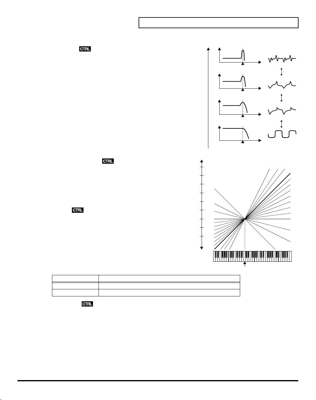
fig.09-32e(Resonance)
Reso (Resonance)
Boosts the cutoff point. As you increase the value, specific
harmonics are emphasized and the sound will become more
unusual, more electronic in nature.
Value:
0–30
100
Tone Parameters
Level
Cutoff Point Frequency
Level
fig.09-33e(CutoffKeyFollow)
KF(Keyfollow (Cutoff Point))
Keyfollow can change the cutoff point depending on the key
played. Just like the Keyfollow of WG pitch, the value
represents how many octaves change over 12 keys.
Value:
-1, -1/2, -1/4, 0, 1, 1/4, 3/8, 1/2, 5/8, 3/4, 7/8, 1, 5/4,
3/2, 2
BP (Bias Point)
You can add a further change (= bias level) to the Keyfollow
curve, and set the range (bias direction) where the bias level is
valid. The bias range is where the bias level is valid on the
keyboard. It can be set with the
range begins) and
Value:
<A1–<C7, >A1–>C7
Display Example
>C4
<C4
bias direction
Example Function
The bias level is only valid on the keyboard above the C4 key.
The bias level is only valid on the keyboard below the C4 key.
bias point
( < or > ).
(where the bias
+3
-1
2
1
0
Value
0
Pitch
(Octave)
-1
-1/2
-1/4
Cutoff Point Frequency
Level
Cutoff Point Frequency
Level
Cutoff Point Frequency
Middle C (C4)
5/4
3/2
2
1
7/8
3/4
5/8
1/2
3/8
1/4
1/8
0
BLevel (Bias Level)
The bias level can be set. “+” values raise the curve, and “-” value lower the curve.
Value:
-7–+7
69
Page 70

Tone Parameters
Keyfollow Adjustment
fig.09-34e(bias/direction)
The curve in the picture represents the Keyfollow value with the bias level added.
• TVF Keyfollow (Cutoff Point): 0
• Bias Direction: >C4
TVF ENV (TVF Envelope)
fig.09-35(LCD_TVF/TVF ENV)
Depth (ENV Depth)
Sets the depth of the TVF ENV modulation that changes the TVF
cutoff Point. Higher values deepen the effect.
Value:
0–100
Middle C (C4)
Angle
0
Value
Velo (Velocity Range)
DKF (Keyfollow (Depth))
TKF (Keyfollow (Time))
70
Sets the sensitivity of the velocity than controls the depth of the
TVF ENV. At higher values, the effect is deeper by playing
harder.
Value:
0–100
This can change the TVF ENV depth depending on the key played. Higher values change the depth more
drastically.
Value:
0–4
fig.09-36(TimeKeyFollow)
This can change the time of the TVF ENV depending on the key
played. Higher values change the time more drastically.
Value:
0–4
Page 71

TVF ENV Time
An envelope curve is determined by times and levels.
fig.09-37e(TvfEnvTime)
Point 1
Point 2
Point 3
Point 4
Tone Parameters
SusLL3L2L1
Key On Key Off
fig.09-38(LCD_TvfEnvTime)
T1 T2 T3 T4 T5
T1 (Time 1)
Sets the time needs to reach point 1 from the moment the key is
pressed.
Value:
0–100
T2 (Time 2)
Sets the time needed to reach point 2 from point 1.
Value:
0–100
T3 (Time 3)
Sets the time needed to reach point 3 from point 2.
Value:
0–100
T4 (Time 4)
Sets the time needed to reach point 4 from point 3.
Value:
0–100
T5 (Time 5)
Sets the time needed to reach point 5 from the moment the key is released.
Value:
0–100
Point 5
EndL
71
Page 72

Tone Parameters
TVF ENV Level
L1 (Level 1)
L2 (Level 2)
L3 (Level 3)
SusL (Sustain Level)
EndL (End Level)
* The End Level is retained until you release and play the key again.
* If the Levels of two adjacent points are set to similar values, the time between these two points may prove to be
fig.09-39(LCD_TvfEnvLevel)
Sets the of point 1.
Value:
0–100
Sets the level of point 2.
Value:
0–100
Sets the level of point 3.
Value:
0–100
This sets the level of point 4.
Value:
0–100
To lower the level after releasing the key, set this to 0, and to raise the level, set it to 100.
Value:
0, 100
shorter than what is actually set, or even zero.
72
Page 73

TVA (Time Variant Amplifier)
TVA
fig.09-40(LCD_TvaTva)
Level
Sets the volume of a Partial. Higher values may cause sound
distortion. If so, lower the value. Even when the Level is set to
zero here, the sound may not be completely muted if the TVA
ENV curve is high.
Value:
0–100
Velo (Velocity Range)
Sets the sensitivity of the velocity that controls the volume of the
sound. “-” values lower the level by harder playing, and “+”
values raise the level by harder playing.
Value:
-50–+50
BP (Bias Point)
You can change the overall volume of the keyboard (= bias level) from the set level, and set the range (bias
direction) where the bias level is valid.
This bias range is where the bias level is valid on the keyboard. It can be set with the bias point (Where he
bias range begins) and bias direction ( < or > ).
Value:
<A1–<C7, >A1–>C7
Tone Parameters
Display Example
>C4
<C4
Function Example
The bias level is only valid on the keyboard above the C4 key.
The bias level is only valid on the keyboard below the C4 key.
BLevel (Bias Level)
The curve ( bias level ) can be set. Lower values make the curve steeper.
Value:
-12–0
Volume Adjustment
fig.09-41e(bias/direction)
0
Value
Angle
C6
• Bias Point:>C6
73
Page 74

Tone Parameters
TVA ENV (Envelope)
fig.09-42(LCD_TvaEnv)
Velo (Velocity Follow (Time 1))
Sets the sensitivity of the velocity than controls the Time 1 of the
TVA ENV. Increasing the sensitivity shortens Time 1, by stronger
playing.
Value:
0–4
fig.09-36(TimeKeyFollow)
TKF (Keyfollow (Time))
This can change the time o the TVA ENV depending on the key
played. 0 to 4 are valid. Higher values change the time more
drastically.
Value:
0–4
TVA ENV Time
An envelope curve is determined by times and levels.
fig.09-37e(TvaEnv)
Point 1
Point 2
Point 3
74
Point 4
SusLL3L2L1
Key On Key Off
fig.09-43(LCD_TvaEnvTime)
T1 T2 T3 T4 T5
T1 (Time 1)
Sets the time needed to reach point 1 from the moment the key is
pressed.
Value:
0–100
T2 (Time 2)
Sets the time needed to reach point 2 from point 1.
Value:
0–100
T3 (Time 3)
Sets the time needed to reach point 3 from point 2.
Value:
0–100
Point 5
EndL
Page 75

T4 (Time 4
Sets the time needed to reach point 4 from point 3.
Value:
0–100
T5 (Time 5)
Sets the time needed to reach point 5 from the moment the key is released.
Value:
0–100
TVA ENV Level
fig.09-44(LCD_TvaEnvLevel)
L1 (Level 1)
Sets the level of point 1.
Value:
0–100
L2 (Level 2)
Sets the level of point 2.
Value:
0–100
L3 (Level 3)
Sets the level of point 3.
Value:
0–100
SusL (Sustain Level)
Sets the level of point 4.
Value:
0–100
Tone Parameters
EndL (End Level)
To lower the level after releasing the key, set this to 0, and to raise the level, set it to 100.
Value:
0, 100
* The End Level remains until the key is released and played again. That is, at a value of 100, the sound remains.
However, the PMC Sound Generator’s One-shot sounds do not remain even when set to 100.
* If the levels of two adjacent points are set to similar values, the time between these two points may prove to be
shorter than what is actually set, or even zero.
75
Page 76

Tone Parameters
MOD (Modulation)
TVF MOD
fig.09-45(LCD_ModTvfMod)
LFO (LFO Select)
Selects the LFO that changes cutoff point periodically (creating
growl effects).
Value:
+1, -1, +2, -2, +3, -3
fig.09-25e(LFO Select)
Display
+1
-1
+2
-2
+3
-3
LFOD (LFO Depth)
Sets the depth of a growl effect. Higher values deepen the effect.
Value:
LFO (Phase)
LFO-1 (+)
LFO-1 (-)
LFO-2 (+)
LFO-2 (-)
LFO-3 (+)
LFO-3 (-)
0–100
Positive Phase (+)
Negative Phase (-)
After (Aftertouch Range)
Sets the sensitivity of the aftertouch that controls the cutoff point. “-” values lower the cutoff point by
stronger Aftertouch, and “+” values raise it.
Value:
76
-7–+7
Page 77

TVA MOD
fig.09-46(LCD_ModTvaMod)
LFO (LFO Select)
Selects the LFO that changes the volume periodically (tremolo
effects) .
Value:
+1, -1, +2, -2, +3, -3
fig.09-25e(LFO Select)
Display
+1
-1
+2
-2
+3
-3
LFOD (LFO Depth)
Sets the depth of the tremolo effect. Higher values deepen the
effect.
Value:
LFO (phase)
LFO-1 (+)
LFO-1 (-)
LFO-2 (+)
LFO-2 (-)
LFO-3 (+)
LFO-3 (-)
0–100
Tone Parameters
Positive Phase (+)
Negative Phase (-)
After (Aftertouch Range)
Sets the sensitivity of the aftertouch that controls the volume. “-” values lower the volume by stronger
aftertouch. And “+” values increase the volume by stronger aftertouch.
Value:
-7–+7
77
Page 78

Settings for the Entire VC-1
Settings that affect the entire operating environment of the VC-1, such as tuning and MIDI message
reception, are referred to as
functions and describes the functions of the different System parameters.
How to Make the System Function Settings
fig.10-01(LCD_ModeMenu)
1.
Press
[MODE]
. The
2.
Touch
<SYSTEM>
fig.10-02(LCD_SystemGeneral)
3.
Move the cursor to the value box of that parameter. Then modify
the value by either turning the
[DEC/-]
.
4.
Repeat steps 3 to make the settings for the System function.
5.
After you have edited the settings of the System function, touch
<Write>
, located in the lower right of the screen.
. The
System functions
MODE MENU
SYSTEM
VALUE dial
. This section explains how to make settings for the System
window appears.
screen appears.
or pressing
[INC/+]
or
78
* Changes you make to the System function settings are only temporary—they will be discarded as soon as the power
is turned off. If you want to keep any changes you’ve made in the system settings, you must save them in VC-1.
When you perform the save procedure, the data that previously occupied the save destination will be lost. However,
the factory setting data can be recovered by performing the Initialization procedure. (Factory Reset; p. 35)
Page 79

fig.10-03(LCD_SystemGeneral)
Sound Setting
Master Tune
Adjusts the overall tuning of the VC-1. The display shows the
frequency of the A4 note (center A).
Value:
427 – 452 Hz
Sound Character
Sets whether the output characteristics of the sound are the same
as those of the D-50 (D-50) or the V-Synth (V-Synth).
Value:
D-50, V-Synth
Digital Freq (Digital Frequency)
Sets the sampling frequency of the digital output.
Value:
44.1, 48, 96 kHz
fig.10-03a(LCD_SystemKeyboard)
Keyboard
Octave (Octave Shift)
Transposes the pitch of the keyboard in 1 octave units.
Value:
-3 – 3
Transpose
Modifies the pitch range of the keyboard in semitone steps.
Value:
-12 – +12
Settings for the Entire VC-1
KBD Sens (Keyboard Sensitivity)
Adjusts the keyboard’s touch.
Value:
LIGHT, MEDIUM, HEAVY
Aftertouch Sens
Specifies the Aftertouch sensitivity. Higher values will allow Aftertouch to be applied more easily.
Normally you will leave this at “50.”
Value:
0 – 100
Display Function
LIGHT
MEDIUM Standard
HEAVY Acoustic piano simulation
Light weight synthesizer
keyboard like
79
Page 80

Settings for the Entire VC-1
fig.10-03b(LCD_SystemPedal)
Pedal Polarity
Hold (Hold Pedal)
Select the polarity of the Hold pedal. On some pedals, the
electrical signal output by the pedal when it is pressed or released
is the opposite of other pedals. If your pedal has an effect opposite
of what you expect, set this parameter to “REVERSE.” If you are
using a Roland pedal (that has no polarity switch), set this
parameter to “STANDARD.”
Value:
STANDARD, REVERSE
Pedal1, Pedal2 (Control Pedal 1, Control Pedal 2)
Selects the polarity of the pedal. On some pedals, the electrical signal output by the pedal when it is
pressed or released is the opposite of other pedals. If your pedal has an effect opposite of what you
expect, set this parameter to “REVERSE.” If you are using a Roland pedal (that has no polarity switch), set
this parameter to “STANDARD.”
Value:
STANDARD, REVERSE
fig.10-04(LCD_SystemMidi)
MIDI
MIDI CH (MIDI Channel)
Sets the
Basic Channel
receives and transmits messages).
Value:
1 – 16
* The transmit change can be set to a different number from the Basic
Channel individually from each Patch (p. 32).
Control
Determines how to receive messages from an external MIDI
device. (
“Key Mode Alteration”
Value:
B.CH, G.CH, MdeOFF
(MIDI channel on which the VC-1
(p. 126))
80
Display
B.CH
(Basic Channel mode)
G.CH
(Global Channel mode)
MdeOFF
(Mode Message OFF mode)
Function
When the VC-1 is being controlled in Mono mode, it receives the Voice
massages (except for Note Event, Pitch Bender) on the Basic Channel
from the external device.
When the VC-1 is being controlled in Mono mode, by an external device
that has a Global Channel (one number smaller than the basic channel)
it can receive all the Voice massages (except for Note Event, Pitch
Bender) On the Global Channel.
In this mode, the VC-1 does NOT receive the Mode massages from the
external MIDI device, but is assigned to the Key mode as set on the
VC-1.
Page 81

Settings for the Entire VC-1
SeparateCH (Receive Channel in Separate Mode)
When
SEP
(Separate Mode) or
be controlled on different channels. The Lower Tone is controlled by the basic channel, and the Upper
Tone is controlled by the receive channel set here. The V-Synth’s keyboard can control only the Upper
Tone.
Value:
1 – 16
* The receive channel of each Patch can be set to a different number from the channel set here. (p. 32)
Local (Local Switch)
Local OFF
Performance information is sent from the MIDI OUT connector, but the VC-1 does NOT make any sound.
The Performance information fed into the MIDI IN connector, however, can control the VC-1’s
synthesizer section.
Value:
Prog.C (Program Change Switch)
To receive or transmit Program Change messages, set this to On.
Program Change messages are transmitted only when a Patch is selected by operating the V-Synth’s
panel buttons, or when the Program Change number to be transmitted is altered also on the V-Synth’s
panel. IN other words, Program Change messages are not transmitted by patch selection with the
Program Change messages sent from an external MIDI device.
Value:
* The Program Change Number of each Patch can be set to a different number from the number set here. (p. 32)
Exclusive (Exclusive Switch)
To receive or transmit Exclusive messages (Roland ID Number only), set this to On,
Value:
separates the keyboard section from the synthesizer section in the VC-1. Therefore,
Off, On
Off, On
Off, On, P-Dump, TxEdit
SEP-S
(Separate Solo Mode) is selected, the Upper and Lower Tones can
P-Dump
or
TxEdit
.
Display
On
P-Dump
TxEDIT
* When set to
by Patch Shift with the pedal switch, or by patch selection with the Program Change messages sent from an external
device.
Bank.S (Bank Select Switch)
To receive or transmit Bank Select messages, set this to On.
Value:
USB MIDI (USB MISI Switch)
If you want to exchange MIDI messages with a sequencer or UNI QUEST editor via USB connector, set
this to On. (
Value:
Function
Normally.
The patch data that you select is transmitted.
The parameter data that you edited is transmitted.
P-Dump
Off, On
Off, On
, the Patch you select is transmitted to an external device. However, it cannot be transmitted
“Exchanging MIDI Messages with Your Computer”
(p. 88))
81
Page 82

Settings for the Entire VC-1
Initializing the System Settings
The current settings of the system functions can be restored to a set of standard settings, or to the factory
settings (System Initialize).
fig.10-04a
1.
Access the System Edit screen.
2.
Touch
<Init>
, located in the lower right of the screen.
3.
If you want the factory settings to be in effect the next time the
VC-1 is powered up, touch
<Write>
to save the settings.
82
Page 83

Connecting to Your Computer via USB
Recovering the System from the CD-ROM
If while running the VC-1 from a computer you happen to delete (format) any of the VC-1’s folders or
files or change file or folder names, the VC-1 will fail to operate correctly. In such instances, recover the
VC-1’s program from the CD-ROM included with the VC-1.
Use the following procedure.
Selecting the V-Synth’s USB Storage Mode (p. 83)
Connecting the V-Synth to Your Computer via USB (p. 84)
Recovering the System
Canceling the USB Connection
(p. 86)
(p. 86)
Selecting the V-Synth’s USB Storage Mode
fig.11-01(ModeMenuSystem)
1.
Turn off the power of VC-1 (V-Synth) once, then pull out the VC-1
from the
2.
Turn on the power of V-Synth again. Wait for the V-Synth to start
up normally.
3.
Press
4.
Touch
fig.11-02(SystemGeneral)
5.
In the left side of the screen, touch the
SYSTEM Com MIDI/USB
6.
Touch
appears.
PC CARD
[MODE]
to access the
<SYSTEM>
<USB Setup>
slot.
V-Synth MODE MENU
. The
SYSTEM Com Master
screen appears.
. The
SYSTEM Com USB Setting
screen appears.
<MIDI USB>
window.
tab. The
window
83
Page 84

Connecting to Your Computer via USB
fig.11-03(System_UsbSetup)
7.
Touch USB Mode
8.
Touch
<OK>
fig.11-04(Warning)
9.
When a
WARNING
<ACCEPT>
10.
In the lower right of the SYSTEM Com MIDI/USB screen, touch
<Write>
to save the system settings.
<Storage>
.
window like the following appears, touch
to close the window.
. USB Storage mode will be selected.
Connecting the V-Synth to Your Computer via USB
The installation procedure will differ depending on your system. Please proceed to one of the following
sections, depending on the system you use.
•
84
Windows XP/2000/Me/98
•
Macintosh
(p. 85)
Windows XP/2000/Me/98
fig.11-05(ModeMenuUsb)
1.
Make sure that the power of the VC-1 is turned off.
2.
Start up your computer.
3.
Connect the V-Synth and your computer using a USB cable.
4.
Turn on the power of V-Synth.
5.
6.
7.
Insert the
Press
Touch
VC-1
into the
[MODE]
to access the
<USB>
. The USB Storage screen appears.
(p. 84)
PC CARD
slot of the V-Synth rear panel.
V-Synth MODE MENU
window.
Page 85

fig.11-06(Connect)
8.
Touch
<PC Card>
to establish the connection with your
computer.
When the USB connection is established for first time, the driver
installation will begin. A dialog box of “Found new hardware”
will appear near the Windows task tray. Installation is completely
automatic. Please wait for it to be completed.
9.
When installation is completed, open My Computer and you will
see a new drive icon.
Connecting to Your Computer via USB
OS
Windows 98/Me/2000
Windows XP
Icon name
Removable Disk
VC-1
Once the V-Synth is connected, you can recover system files by operating your computer. (p. 86)
Macintosh
fig.11-05(ModeMenuUsb)
1.
Make sure that the power of the V-Synth is turned off.
2.
Start up your computer.
3.
Connect the V-Synth and your computer using a USB cable.
4.
Turn on the power of V-Synth.
5.
Insert the
6.
Press
7.
Touch
fig.11-06(Connect)
8.
Touch
computer.
9.
When the USB connection is established, a new drive icon will
appear on your desktop.
VC-1
into the
[MODE]
to access the
<USB>
. The USB Storage screen appears.
<PC Card>
PC CARD
V-Synth MODE MENU
to establish the connection with your
slot of the V-Synth rear panel.
window.
Once the V-Synth is connected, you can recover system files by operating your computer. (p. 86)
85
Page 86

Connecting to Your Computer via USB
Recovering the System
1.
Insert the V-Card CD-ROM into the CD-ROM drive of your computer (
2.
Using your computer, copy the
(overwriting it) within the VC-1.
* Do not perform the following actions while “Access” (the access indicator) in the USB Storage screen is blinking.
Doing so may cause your computer to freeze, and may also damage the files in the drive.
• Do not disconnect the USB cable
• Do not remove the PC card while it is being accessed
• Do not sleep, restart, or shut down your computer
• Do not turn off the power of V-Synth.
SYRB1.BIN
Canceling the USB Connection
When recovery of the system data is finished, stop the USB connection to safely disconnect the USB cable
and turn off the power to the V-Synth.
fig.11-10(AccessLamp)
1.
In the V-Synth’s
(the access indicator) is not blinking.
2.
Perform the “Eject” operation on your computer.
2-1.
Windows 98/Me/2000/XP:
In My Computer, right-click the “Removable Disk” icon
and execute “Eject.”
2-2.
Macintosh:
Select the VC-1 drive icon on your desktop, and either
choose “Eject” from the “Special” menu, or drag the icon
into the trash.The drive icon will disappear from the
desktop, and the USB connection will be cancelled.
USB Storage
screen, make sure that “
NOT
V-Synth driver CD-ROM!).
file on the V-Card CD-ROM to the
Access
”
SYRB1.BIN
file
86
3.
Press
[EXIT]
. The USB Storage screen will close.
You can now safely disconnect the USB cable or turn off the power to the V-Synth with the USB cable still
connected.
fig.11-11(Warning2)
* If you press
computer, a WARNING window like the following will appear. Touch
<EXECUTE>
“Eject” operation on your computer.
[EXIT]
without performing the “Eject” operation on your
to close this window only if you are unable to perform the
Page 87
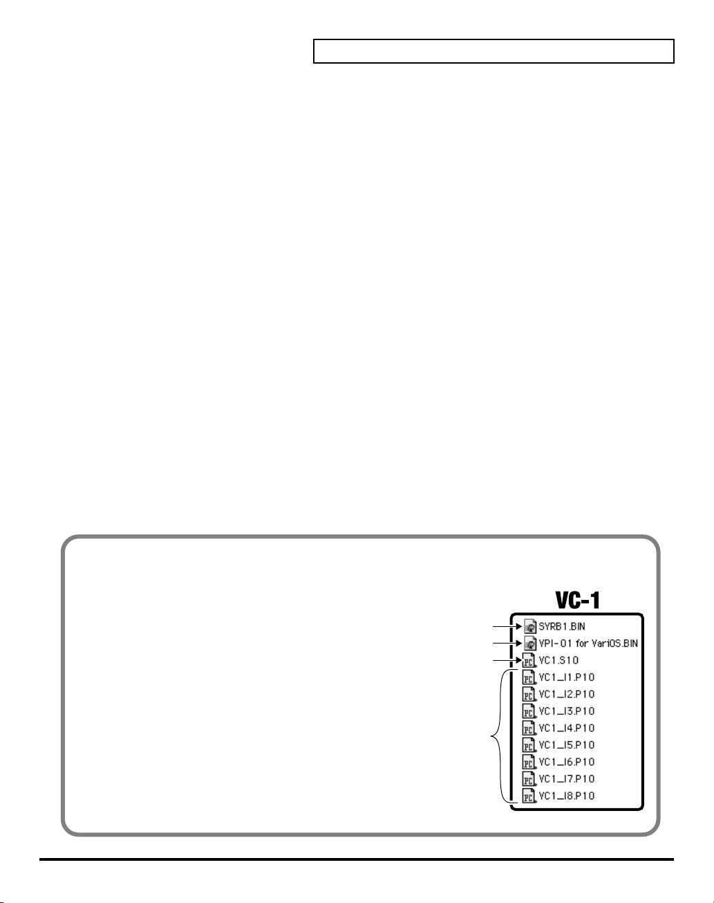
Connecting to Your Computer via USB
The VC-1’s File Structure
As seen from your computer, the VC-1’s file structure is as follows.
fig.11-09e(Vc1FileStructure)
• You can use the computer to copy (back up)
these files to the computer (e.g., the hard disk).
• Do not perform operations on your computer to
erase (format) or rename these folders or files.
If the VC-1 fails to operate correctly, use the CD-
ROM included with the VC-1 to perform the VC-
1 recovery. This will erase all the data that has
been saved on the VC-1.
V-Synth System Program
Var iOS System Program
System Parameter
Patches of Internal Bank
87
Page 88

Connecting to Your Computer via USB
Exchanging MIDI Messages with Your Computer
What is the USB MIDI Driver?
fig.11-12e(MidiDriver)
The USB MIDI Driver is a software which
passes data between the VC-1 and the
application (sequencer software, UniQuest
editor, etc.) that is running on the USB-
connected computer.
The USB MIDI Driver sends data from the
application to the VC-1, and passes data
from the VC-1 to the application.
Computer
Application
Driver
USB
USB connecter
USB cable
USB connecter
V-Synth
In order to use the VC-1 as a USB MIDI device from your computer, you must first install the USB MIDI
driver. The USB MIDI driver is on the “V-Synth Driver CD-ROM.” (
NOT
VC-1 CD-ROM!)
In order to use USB in MIDI mode, you must install the driver from the V-Synth Driver CD-ROM into
your computer (included the V-Synth package).
The correct driver and the installation procedure will depend on your system and on the other programs
you are using. Be sure to read the Readme file on the CD-ROM before installation.
OS
Windows XP/2000
Windows Me/98
Macintosh (OMS)
Macintosh (FreeMIDI)
Mac OS X
Folder
\Midi\Usb_xp2k\Readme_e.htm
\Midi\Usb_me98\Readme_e.htm
\OS_9\English\Readme_OMS-E.HTM
\OS_9\English\Readme_FM-E.HTM
\OS_X\Readme-E.HTM
* The most recent version of the USB-MIDI driver can be downloaded from the Roland Website;
http://www.roland.com/products/en/VC-1/
. This URL may change without notice.
88
Page 89

Using with the VariOS
Panel Description............................................................................................................ 90
VariOS Menu.................................................................................................................... 93
Try Out the Sounds......................................................................................................... 94
Turning On the Power.......................................................................................................94
Selecting Patches and Playing Sounds............................................................................ 95
Determining the MIDI Keyboard Routings..........................................................................................96
Setting the MIDI Receive Channel......................................................................................................... 97
Selecting Patches with the VALUE knob.............................................................................................. 97
Applying Effects to the Sound....................................................................................... 98
Applying Effects by Turning Knobs ...............................................................................98
How to Make the Patch Factors .......................................................................................99
Transferring Patches To and From the D-50/550 .......................................................101
Transferring Patches from the D-50 to the VC-1 .........................................................101
Transferring Patches from the VC-1 to the D-50/550.................................................104
Overview of the VC-1 ....................................................................................................107
Memory Structure............................................................................................................107
The Basic Concept of a Tone...........................................................................................108
Structure of Tone Parameters.........................................................................................111
Creating Patches........................................................................................................... 113
Naming a Patch ................................................................................................................113
Saving Patches.................................................................................................................. 114
Initializing Patch Settings ...............................................................................................115
Reset to Default Factory Settings................................................................................... 115
Copying a Patch Bank .....................................................................................................116
Settings for the Entire VC-1 .........................................................................................117
How to Make the System Function Settings ................................................................117
Saving the System Settings ............................................................................................. 120
Initializing the System Settings (Init)............................................................................ 120
Connecting to Your Computer via USB ......................................................................121
Recovering the System from the CD-ROM ..................................................................121
Exchanging MIDI Messages with Your Computer..................................................... 124
89
Page 90

Panel Description
When using the VariOS with the
correspond to the functions ascribed to these controls on the VariOS’s panel. Here is a description of the
names and functions in each section of the VariOS when it is used with the VC-1. Please read this material
together with “Names of Things and What They Do” in the VariOS User Guide. Controls whose functions
do not match what is shown on the panel are indicated with a mark.
Front Panel
fig.12-01(VariosFront)
1
PC CARD Slot
The
VC-1
2
C1/C2/C3 Knobs
Display
C1
(PITCH)
C2
(TIME)
C3
(FORMANT)
1
can be inserted here.
Functions
The
This sets the volume of the
This sets the
OFF, C3
VC-1
, the actual functions of the VariOS’s buttons and knobs may not
2 3
volume balance
knob may have no effect.
of the Upper and the Lower Tone can be change.
portamento time
5 6 8 9 10 11
4
7
reverb
and direct sounds.
from one note to another. If Portamento Switch (p. 99) is set to
90
3
Indicators
Display
MIDI
TEMPO
PC
USB
4
Display
Various information is shown here according to the operations you perform.
* The explanations in this manual include illustrations that depict what should typically be shown by the display.
Note, however, that your unit may incorporate a newer, enhanced version of the system (e.g., includes newer
sounds), so what you actually see in the display may not always match what appears in the manual.
Functions
Lights when a MIDI message is received.
This does NOT function for VC-1.
Lights when the MIDI mode of the VariOS is “PC” (p. 119).
Lights when connected to a computer via USB.
Page 91

5
MENU Button
Accesses the various functions of the VariOS.
6
EXIT Button
Returns you to the previously displayed screen. Depending on the content of the menu, this button also
functions as CANCEL.
7
CURSOR Buttons
Used to move the cursor.
8
VALUE Dial
Turn this dial to edit a value. Pressing the VALUE dial will function as ENTER (confirm). If you turn the
VALUE dial while pressing it, the value will change in larger steps.
9
VOLUME Knob
Adjusts the overall volume that is output from the MAIN OUT jacks and the PHONES jack. By pressing
the VOLUME knob you can audition (preview) the current sample.
10
PHONES Jack
You can connect a set of headphones to this jack. Use headphones with an impedance in the range of 32 –
600 ohms.
Panel Description
11
POWER Switch
fig.sw-e
Turns the power of the VariOS on/off (p. 94). The power is on
when the switch is in the inward position, and off when the switch
is in the outward position.
Power is ON
Switch is depressed.
When
Power is OFF
Switch is Releaseed..
When
91
Page 92

Panel Description
Rear Panel
fig.12-02(VariosRear)
1 2 3 4 5 6 7
1
AC Inlet
Connect the supplied power cord here.
2
Grounding Terminal
Depending on the circumstances of a particular setup, you may experience a discomforting sensation, or
perceive that the surface feels gritty to the touch when you touch this device, microphones connected to it,
or the metal portions of other objects. This is due to an infinitesimal electrical charge, which is absolutely
harmless. However, if you are concerned about this, connect the ground terminal (see figure) with an
external ground. When the unit is grounded, a slight hum may occur, depending on the particulars of
your installation. If you are unsure of the connection method, contact the nearest Roland Service Center,
or an authorized Roland distributor, as listed on the “Information” page.
Unsuitable places for connection:
Water pipes (may result in shock or electrocution)
Gas pipes (may result in fire or explosion)
Telephone-line ground or lightning rod (may be dangerous in the event of lightning)
92
3
USB Connector
Use a USB cable to connect the VariOS to your computer.
4
MIDI Connectors
Connect external MIDI devices here (p. 101). Use MIDI cables (sold separately) to make connections.
Display
IN
OUT
5
DIGITAL OUT Connectors
These jacks output digital audio signals (stereo). Two types are provided; optical and coaxial. Output
settings are made in the screen where you specify the effect signal flow. You can use both types of OUT
connector simultaneously; they will output the same sound.
6
INPUT Jacks
Not used with the VC-1.
7
OUTPUT Jacks
Connect your amp or mixer to these jacks.
Display Functions
DIRECT OUT
MAIN OUT
Functions
Receives MIDI messages from an external device.
Transmits MIDI messages to an external device.
This does NOT function for VC-1.
Output the audio signal in stereo. If you want to use monaural output, connect only the L jack.
Page 93

VariOS Menu
A number of Patch Factors and Parameters are shown in a Menu display. There are several Menu displays
as shown below.
Menu
Menu1 Patch Setting
1-1 Chase Switch
1-2 Portament Switch
1-3 Key Mode
1-4 Split Point
1-5 Partial Mute
Menu2 MIDI Setting
2-1 MIDI CH
2-2 Control
2-3 Separate CH
2-4 ProgramChange Sw
2-5 Exclusive Sw
2-6 BankSelect Sw
Menu3 Utility
3-1 Patch Name
3-2 Patch Initialize
3-3 Bank Copy
3-4 Bank Dump
3-5 Factory Reset
Menu4 System
4-1 Master Tune
4-2 Sound Character
4-3 MIDI Mode
4-4 C1/C2/C3 Knob
4-5 System Save
4-6 System Initialize
Menu5 Patch Write
Menu6 Bank Save
Page
(p. 99)
(p. 99)
(p. 99)
(p. 100)
(p. 100)
(p. 117)
(p. 117)
(p. 118)
(p. 118)
(p. 118)
(p. 118)
(p. 113)
(p. 115)
(p. 116)
(p. 104)
(p. 115)
(p. 119)
(p. 119)
(p. 119)
(p. 119)
(p. 120)
(p. 120)
(p. 114)
(p. 104)
93
Page 94

Try Out the Sounds
Turning On the Power
To prevent malfunction and/or damage to speakers or other devices, always turn down the volume, and
turn off the power on all devices before making any connections.
fig.12-03e(ConnectionImage)
1.
Before hooking anything up, make sure that the power on all of
your gear is turned OFF.
2.
Connect the VariOS to your amp/speaker system.
3.
After correctly inserting the VC-1 into the PC card slot in the
VariOS’s front panel, switch ON the POWER switch.
* Carefully insert the PC card all the way in – -until it is firmly in place.
* This unit is equipped with a protection circuit. A brief interval (a few
seconds) after power up is required before the unit will operate normally.
* Always make sure to have the volume level turned down before switching
on power. Even with the volume all the way down, you may still hear
some sound when the power is switched on, but this is normal, and does
not indicate a malfunction.
* Never insert or pull out while the VC-1 (VariOS) is turned on.
MIDI IN
MIDI OUT
MIDI Keyboard
Monitor Speaker
94
4.
Turn on the power for any connected amplifiers or speakers.
5.
Wait for the VC-1 to start up. When it has started up normally, a screen like the following will appear. The
display shows the selected Patch.
fig.12-04e(Card&LCD_default)
Patch Number Cursor
Patch Name
Page 95

Selecting Patches and Playing Sounds
Try Out the Sounds
The VC-1 comes with a wide range of onboard sounds, including single tones called
A Patch is represented by a
fig.03-03e(PatchBankImage)
Patch bank (Pre1–6)
Pre6
Pre5
Pre4
Pre3
Pre2
Pre1
Number
1
2 3 4 5 6 7 8
1
2
3
Bank
4
5
6
7
8
Patch Banks
Pre1
Pre2
Pre3
Pre4
Pre5
Pre6
Int1
Int2
Int3
Int4
Int5
Int6
Int7
Int8
Included patches Overwrite Remarks
D-50
VC-1
PN-D50-01
PN-D50-02
PN-D50-03
PN-D50-04
same as Pre1
same as Pre2
same as Pre3
same as Pre4
same as Pre5
same as Pre6
(blank)
(blank)
Patch Bank
Int1
Bank
(Pre1 – 6, Int1 – 8), a
Patch bank (Int1–8)
Int6
Int5
Int4
Int3
Int2
Number
1
2 3 4 5 6 7 8
1
2
3
4
5
6
7
8
Patch No.: I1-72Patch No.: P1-34
No Original D-50 preset patches
No
No D-50/D-550 sound library
No D-50/D-550 sound library
No D-50/D-550 sound library
No D-50/D-550 sound library
Yes -
Yes -
Yes -
Yes -
Yes -
Yes -
Yes -
Yes -
Bank
Int8
Int7
Newly added patches
(1 – 8) and a
Number
patches
(1 – 8).
.
Use the following procedure.
Determining the MIDI Keyboard Routings.
Setting the MIDI Receive Channel
(p. 97)
Selecting Patches with the VALUE knob
(p. 96)
(p. 97)
95
Page 96

Try Out the Sounds
Determining the MIDI Keyboard Routings.
fig.12-05
1.
Press the
screen.
2.
Turn the
[VALUE]
fig.12-06
3.
Turn the
[VALUE]
4.
Turn the
fig.12-07
MIDI Mode
Selects the MIDI keyboard routing. Normally, you should set the
MIDI mode to “PC.”
Value:
[MENU]
[VALUE]
knob.
[VALUE]
knob.
[VALUE]
PC, Internal
button so it’s lighted, and access the
knob to select “
knob to select “
MIDI Settings
MIDI Mode
,” and press the
,” and press the
knob to select a routing.
MENU
Display
PC
Internal
Description Routing
When using a USB connection,
the MIDI connectors on the
rear panel of the VariOS will
function as a USB MIDI
interface (Roland VariOS
External MIDI).
When USB is not connected
(and when your computer is
not powered up), the MIDI
connectors on the rear panel of
the VariOS are connected
directly to the sound generator
section.
The MIDI connectors of the
rear panel of the VariOS are
connected directly to the sound
generator section.
Var iOS MIDI– –VariOS External MIDIIN OUT IN OUT
Var iOS MIDI–
Var iOS MIDI– –VariOS External MIDIIN OUT IN OUT
Computer
Sequencer
UniQuest (Editor)
Sound
Generator
Section
Sound
Generator
Section
Computer
Sequencer
UniQuest (Editor)
Sound
Generator
Section
; USB
MIDI OUT
MIDI IN
Var iOS
MIDI OUT
MIDI IN
Var iOS
; USB
MIDI OUT
MIDI IN
Var iOS
96
Page 97

5.
Press the
* The “
mode is selected. When dark, “
[MENU]
PC indicator
button to turn off its illumination.
” on the front panel of the VariOS shows the current MIDI Mode status. When this is lit, “PC”
Internal
” mode is selected.
Setting the MIDI Receive Channel
Try Out the Sounds
The VariOS will receive
you’ve connected a MIDI keyboard, set this channel to match the transmit channel of your MIDI
keyboard.
fig.12-11
1.
Press the
screen.
2.
Turn the
[VALUE]
fig.12-12
3.
Turn the
[VALUE]
4.
Turn the
fig.12-13
MIDI CH
Sets the
receives and transmits messages).
Value:
5.
Press the
[MENU]
[VALUE]
knob.
[VALUE]
knob.
[VALUE]
Basic Channel
1 – 16
[MENU]
Note-on
button so it’s lighted, and access the
knob to select “
knob to select “
knob to specify the receive channel (1 – 16).
(MIDI channel on which the VC-1
button to turn off its illumination.
and
Control change
MIDI Setting
MIDI CH
messages on the channel you specify here. If
MENU
,” and press the
,” and press the
Selecting Patches with the VALUE knob
1.
Make sure the
several times until the
2.
Play the keyboard to hear what the selected patch sounds like. To change to a different patch, turn the
[VALUE]
• At this time you can switch more rapidly by holding down
operations.
• Use the
Bank Number)
fig.12-14e
Cursor Cursor
PATCH TOP
knob.
[]
or
screen is displayed. If the
PATCH TOP
[]
buttons to move the cursor to the value you want to edit. (Patch
screen appears.
PATCH TOP
screen is not displayed, press
[VALUE]
knob while you perform these
[EXIT]
97
Page 98

Applying Effects to the Sound
The performance controlling functions (we call them
factors
in this manual) in each Patch can be edited
by taking the following procedure.
A patch consists of several
fig.05-01e
Key Mode
Factors
as show below.
Tone Tune
UPPER Tone
Var iations of
Control Functions
LOWER Tone
Tone Tune
Tone
Balance
Output Mode
(Reverb, etc.)
Applying Effects by Turning Knobs
By turning the
been assigned to them.
* How each Control Function actually affects the sound differs depending on the individual patch. Some Patches may
not be affected at all.
[C1], [C2]
and
[C3]
knobs while you play, you can control the various functions that’ve
98
Display
C1
(PITCH)
C2
(TIME)
C3
(FORMANT)
Description
The
volume balance
This sets the volume of the
This sets the
C3
knob may have no effect.
of the Upper and the Lower Tone can be change.
portamento time
reverb
and direct sounds.
from one note to another. If Portament Switch (p. 99) is set to
OFF
,
Page 99

How to Make the Patch Factors
The Display shows several Factors at a time. If necessary, Scroll up or down the Display to find the Factor
to be edited.
fig.12-16
1.
Press the
screen.
2.
Turn the
[VALUE]
3.
Turn the
4.
Turn the
5.
Repeat steps 3 – 4 to set patch factors.
6.
If you wish to save the changes you’ve made, perform the Save operation (p. 114). If you return to the
PATCH TOP
patch settings have been modified.
[MENU]
button so it’s lighted, and access the
[VALUE]
knob.
[VALUE]
[VALUE]
knob to select “
knob to select the factor that you want to edit, and press the
knob to specify the value, then press
screen without saving, the
Patch Settings
PATCH TOP
MENU
,” and press the
[EXIT]
screen will indicate
Applying Effects to the Sound
[VALUE]
.
<>
knob.
, reminding you that the
* If you turn off the power or select a different patch while the display indicates
lost.
fig.12-18
Chase Switch
Switches the Chase function on and off. The Chase Play function
makes it possible to output the Lower Tone slightly later than the
Upper Tone, which is actually played on the keyboard. This
function, however, is only available in
Value:
Off, On
fig.12-19
Portament Switch
Switches the Portamento function on and off. Portamento is a
slide from one pitch to another, and is often used for violin
performance.
Value:
Off, On
fig.12-20
Key Mode
Key Mode
keyboard.
Value:
Split-LS, Separate-S
refers to the Upper and Lower Tones are played on the
Whole, Dual, Split, Separate, Whole-S, Dual-S, Split-US,
Dual
or
Whole
Key Mode.
<>
,” your edited patch will be
99
Page 100

Applying Effects to the Sound
Display Description
Whole
Dual
Split
Separate
Whole-S
(Whole Solo)
Dual-S
(Dual Solo)
Split-US
(Split Upper Solo)
Split-LS
(Split Lower Solo)
Separate-S
(Separate Solo)
*
Poly Mode
fig.12-21
or
Split Point
The Split Point can be changed as follows.
Value:
C2 – C7
fig.05-14e
Upper Tone can be played in 16 voice polyphony
Both Upper and Lower Tones are played by each key in 8 voices polyphony.
The Split mode divides the keyboard into upper and lower sections, where two different Tones
can be played in 8 voices polyphony. That is, the VC-1 works like two 8 voice synthesizers. The
Split Point
indication.
This mode is effective when an external MIDI device is controlling the VC-1.(
Implementation”
The Upper Tone is monophonic.
Both Upper and Lower Tones are monophonic.
The Upper Tone is monophonic, and the Lower Tone is 8 voices polyphonic.
The Lower Tone is monophonic, and the Upper Tone is 8 voices polyphonic.
This mode is effective when an external a MIDI device is controlling the VC-1. (
Implementation”
Mono Mode
(where the keyboard is divided into two sections) is shown next to the Key Mode
“MIDI
(p. 140))
(p. 140))
is another element that determines how to output the UPPER and LOWER Tones.
“MIDI
100
C2–B2 C3–B3 C4–B4 C5–B5 C6–B6
(middle C)
fig.12-23
Partial Mute
When editing a Partial parameter, nay Partial sound can be
muted.
Value (left side):
Value (right side):
L1, L2, U1, U2
Off, On
C7
 Loading...