

Roland SRX STUDIO Owner's Manual
SRX STUDIO Software Synthesizer
Owner’s Manual
© 2019 Roland Corporation 01

Introduction
For details on the settings for the DAW software that you’re using, refer
to the DAW’s help or manuals.
About Trademarks
• VST is a trademark and software of Steinberg Media Technologies GmbH.
• Roland is a registered trademark or trademark of Roland Corporation in the United States and/or other
countries.
• Company names and product names appearing in this document are registered trademarks or
trademarks of their respective owners.
2

Contents
Introduction . . . . . . . . . . . . . . . . . . . . . . . . . . . . . . . . . . . . . . . . . . . . . . . 2
Screen Structure . . . . . . . . . . . . . . . . . . . . . . . . . . . . . . . . . . . . . . . . . . . 4
Using SRX STUDIO . . . . . . . . . . . . . . . . . . . . . . . . . . . . . . . . . . . . . . . . . 5
How to Edit Values . . . . . . . . . . . . . . . . . . . . . . . . . . . . . . . . . . . . . . . . 5
Initializing a value. . . . . . . . . . . . . . . . . . . . . . . . . . . . . . . . . . . . . . . . . 5
About the KEYBOARD button. . . . . . . . . . . . . . . . . . . . . . . . . . . . . . . 5
Overview of the SRX STUDIO. . . . . . . . . . . . . . . . . . . . . . . . . . . . . . . 6
How the SRX STUDIO is Organized . . . . . . . . . . . . . . . . . . . . . . . . . . 6
How a Patch is Structured . . . . . . . . . . . . . . . . . . . . . . . . . . . . 6
How a Rhythm Set is Structured . . . . . . . . . . . . . . . . . . . . . . . 6
Calculating the Number of Voices Being Used . . . . . . . . . . . 6
About the Effects . . . . . . . . . . . . . . . . . . . . . . . . . . . . . . . . . . . . 7
Memory and Bank . . . . . . . . . . . . . . . . . . . . . . . . . . . . . . . . . . . . . . . . . 8
What is a Memory? . . . . . . . . . . . . . . . . . . . . . . . . . . . . . . . . . . . . . . . . 8
Bank . . . . . . . . . . . . . . . . . . . . . . . . . . . . . . . . . . . . . . . . . . . . . . . . . . . . 8
Changing to Other Bank. . . . . . . . . . . . . . . . . . . . . . . . . . . . . . 8
Exporting the Bank . . . . . . . . . . . . . . . . . . . . . . . . . . . . . . . . . . 8
Importing a Bank . . . . . . . . . . . . . . . . . . . . . . . . . . . . . . . . . . . . 8
Creating/Deleting a Bank . . . . . . . . . . . . . . . . . . . . . . . . . . . . . 8
Renaming a Bank . . . . . . . . . . . . . . . . . . . . . . . . . . . . . . . . . . . . 8
Category. . . . . . . . . . . . . . . . . . . . . . . . . . . . . . . . . . . . . . . . . . . . . . . . . 9
Memory . . . . . . . . . . . . . . . . . . . . . . . . . . . . . . . . . . . . . . . . . . . . . . . . . 9
Loading a Memory. . . . . . . . . . . . . . . . . . . . . . . . . . . . . . . . . . . 9
Saving the Memory . . . . . . . . . . . . . . . . . . . . . . . . . . . . . . . . . . 9
Renaming the Memory. . . . . . . . . . . . . . . . . . . . . . . . . . . . . . . 9
Changing the Order of the Memories . . . . . . . . . . . . . . . . . . 9
EFFECTS Parameters . . . . . . . . . . . . . . . . . . . . . . . . . . . . . . . . . . . . . . . 34
Applying Effects . . . . . . . . . . . . . . . . . . . . . . . . . . . . . . . . . . . . . . . . . . 34
Effect Settings . . . . . . . . . . . . . . . . . . . . . . . . . . . . . . . . . . . . . . . . . . . . 34
Signal Flow and Parameters (ROUTING). . . . . . . . . . . . . . . . . 34
Multi-Effect Settings (MFX) . . . . . . . . . . . . . . . . . . . . . . . . . . . 35
Chorus and Reverb Settings. . . . . . . . . . . . . . . . . . . . . . . . . . . 36
Effects List . . . . . . . . . . . . . . . . . . . . . . . . . . . . . . . . . . . . . . . . . . . . . . . . . 37
Multi-Effects Parameters (MFX) . . . . . . . . . . . . . . . . . . . . . . . . . . . . . 37
About RATE and DELAY TIME . . . . . . . . . . . . . . . . . . . . . . . . . . . . . . . 38
When Using 3D Effects . . . . . . . . . . . . . . . . . . . . . . . . . . . . . . . . . . . . 38
About the STEP RESET function . . . . . . . . . . . . . . . . . . . . . . . . . . . . . 38
Chorus Parameters. . . . . . . . . . . . . . . . . . . . . . . . . . . . . . . . . . . . . . . . 69
Reverb Parameters . . . . . . . . . . . . . . . . . . . . . . . . . . . . . . . . . . . . . . . . 69
Settings . . . . . . . . . . . . . . . . . . . . . . . . . . . . . . . . . . . . . . . . . . . . . . . . . . . . 10
Option . . . . . . . . . . . . . . . . . . . . . . . . . . . . . . . . . . . . . . . . . . . . . . . . . . 10
Detailed Editing for a Patch (PATCH Parameters). . . . . . . . . . . 11
How to Edit a Patch . . . . . . . . . . . . . . . . . . . . . . . . . . . . . . . . . . . . . . . 11
Copying/Pasting Patch Parameters . . . . . . . . . . . . . . . . . . . . 11
TONE SWITCH/SELECT. . . . . . . . . . . . . . . . . . . . . . . . . . . . . . . . 11
Stereo Wave Settings (Set Stereo Function) . . . . . . . . . . . . . 12
PATCH Parameters . . . . . . . . . . . . . . . . . . . . . . . . . . . . . . . . . . . . . . . . 13
COMMON . . . . . . . . . . . . . . . . . . . . . . . . . . . . . . . . . . . . . . . . . . 13
STRUCTURE . . . . . . . . . . . . . . . . . . . . . . . . . . . . . . . . . . . . . . . . . 15
WG + PITCH. . . . . . . . . . . . . . . . . . . . . . . . . . . . . . . . . . . . . . . . . 17
TVF . . . . . . . . . . . . . . . . . . . . . . . . . . . . . . . . . . . . . . . . . . . . . . . . 19
TVA . . . . . . . . . . . . . . . . . . . . . . . . . . . . . . . . . . . . . . . . . . . . . . . . 21
LFO . . . . . . . . . . . . . . . . . . . . . . . . . . . . . . . . . . . . . . . . . . . . . . . . 23
VELOCITY & KEY RANGE . . . . . . . . . . . . . . . . . . . . . . . . . . . . . . 25
MATRIX CONTROL . . . . . . . . . . . . . . . . . . . . . . . . . . . . . . . . . . . 26
CONTROL SW . . . . . . . . . . . . . . . . . . . . . . . . . . . . . . . . . . . . . . . 26
Detailed Editing for a Rhythm Set (RHYTHM Parameters) . . 28
How to Edit a Rhythm Set . . . . . . . . . . . . . . . . . . . . . . . . . . . . . . . . . . 28
Copying/Pasting Rhythm Parameters . . . . . . . . . . . . . . . . . . 28
WG . . . . . . . . . . . . . . . . . . . . . . . . . . . . . . . . . . . . . . . . . . . . . . . . 28
Stereo Wave Settings (Set Stereo Function) . . . . . . . . . . . . . 28
RHYTHM Parameters . . . . . . . . . . . . . . . . . . . . . . . . . . . . . . . . . . . . . . 29
COMMON . . . . . . . . . . . . . . . . . . . . . . . . . . . . . . . . . . . . . . . . . . 29
WG . . . . . . . . . . . . . . . . . . . . . . . . . . . . . . . . . . . . . . . . . . . . . . . . 29
PITCH + TVF. . . . . . . . . . . . . . . . . . . . . . . . . . . . . . . . . . . . . . . . . 30
TVA + VELOCITY . . . . . . . . . . . . . . . . . . . . . . . . . . . . . . . . . . . . . 32
3
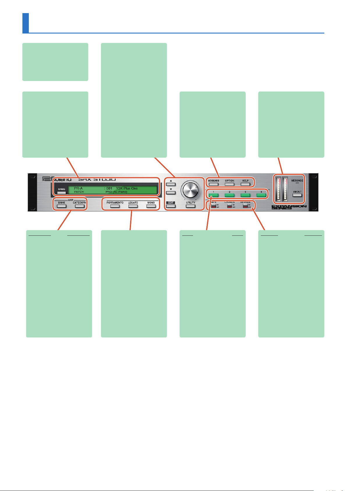
Screen Structure
Main window
Here you can select sounds, turn
effects on/off, and access windows.
[NAME] button
Renames a memory.
Patch Memory name
This area shows the name of the
selected memory.
[MASTER LEVEL] knob
Adjusts the overall volume.
[H] [I] buttons
Select the next or previous memory.
[EDIT] button
Accesses the edit screen.
[UTILITY] button
Allows you to copy or paste groups of
parameters (such as tone or MFX).
[KEYBOARD] button
Shows/hides the keyboard window.
[OPTION] button
Allows you to make various settings
and authorizations.
[HELP] button
Displays help.
[MESSAGE] indicator
Lights when performance data is
received.
[ABOUT] button
Here you can view information about
the SRX STUDIO.
Level meter
Displays output levels of the
SRX STUDIO.
LIST
Displays a list of sounds. You can select
a sound from the list.
[BANK] button
Displays a list organized by bank.
[CATEGORY] button
Displays a list organized by category.
[PORTAMENTO] button
Turns portamento on/off.
[LEGATO] button
This setting specifies whether the
Legato Switch will be used (ON) or
not (OFF).
With the LEGATO SW “ON,” pressing
a key while continuing to press a
previous key causes the note to
change pitch to the pitch of the most
recently pressed key, sounding all
the while.
[MONO/POLY] button
When the button is lit, the instrument
plays monophonically (mono).
When the button is unlit, the
instrument plays polyphonically (poly).
TONE SWITCH
[1 ] [2] [3] [4] buttons
Select the tone(s) that will be heard.
EFFECTS
Press these buttons to turn on/off the
MFX, chorus, or reverb effects.
[REVERB] button
Turns reverb on/off.
[CHORUS] button
Turns chorus on/off.
[MFX] button
Turns multi-effect on/off.
4
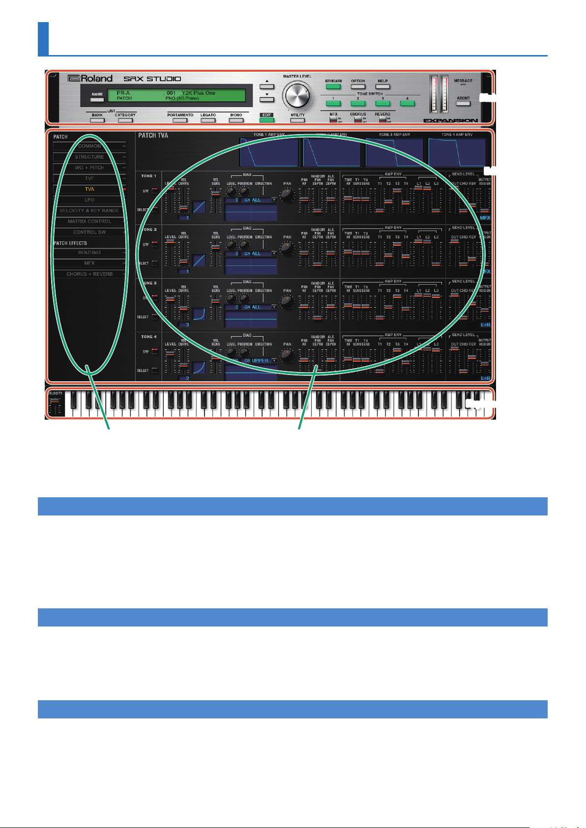
Using SRX STUDIO
Main window
Edit window
Keyboard window
Navigation window Parameter window
5 In the navigation window, you can click various buttons to choose the parameters that are shown in the parameter window.
5 The parameter window shows an editing screen for the parameters that you chose in the navigation window.
5 The edit window includes both the parameter window and the navigation window.
How to Edit Values
You can edit values by clicking (and dragging) the buttons, sliders, or knobs.
5 If you feel that the sliders and knobs in the panel are too small, and find it difficult to make detailed settings, try clicking (and holding) a
knob or slider and then dragging the mouse farther away. This lets you set the value at any position as long as you continue holding down
the mouse button. When doing so, you will be able to make precise adjustments to the value whenever the mouse cursor is away from the
center of the knob or slider.
5 When a value is shown, you can use the cursor keys (up/down/left/right) or mouse wheel to edit the value.
Initializing a value
Windows 7/8.1/10 Users
You can initialize the value of a parameter by holding down the Ctrl key of the computer and clicking the slider or knob of that parameter.
Macintosh Users
You can initialize the value of a parameter by holding down the command key of the computer and clicking the slider or knob of that parameter.
About the KEYBOARD button
When you click the [KEYBOARD] button located in the top line of the main window, the Keyboard window will appear, allowing you to transmit note
messages by clicking the mouse.
If you drag the Velocity slider located at the left edge of the keyboard window all the way down, the value changes to "VARIABLE." With this setting, the
velocity changes according to the position of the keyboard that you click.
Clicking the top edge of the keyboard produces minimum velocity, and clicking the bottom edge produces maximum velocity.
5
Overview of the SRX STUDIO
How the SRX STUDIO is Organized
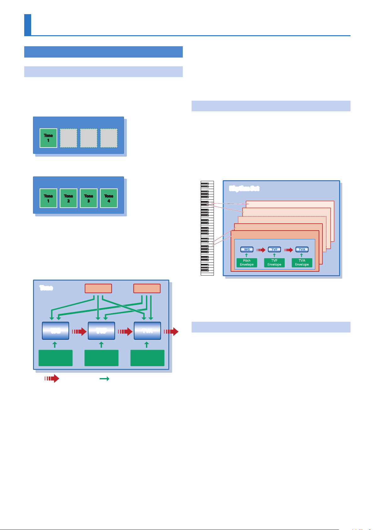
How a Patch is Structured
Patches are the basic sound configurations that you play during a
performance. Each patch can be configured by combining up to four tones.
Each tone can be turned on/off individually, allowing you to select the
tones that will produce sound.
Patch
Tone
Example 1: A Patch consisting of only one Tone ( Tones
2–4 are turned off).
Patch
Tone
Example 2: A Patch consisting of four Tones.
Tone
1
Tone
1
Tone
On the SRX STUDIO, the tones are the smallest unit of sound. However,
it is not possible to play a tone by itself. The patch is the unit of sound
which can be played, and the tones are the basic building blocks which
make up the patch.
Tone
2
Tone
2
Tone
3
3
4
Tone
4
LFO (Low Frequency Oscillator)
Use the LFO to create cyclic changes (modulation) in a sound. The
SRX STUDIO has two LFOs. Either one or both can be applied to effect
the WG (pitch), TVF (filter) and/or TVA (volume). When an LFO is applied
to the WG pitch, a vibrato effect is produced. When an LFO is applied
to the TVF cutoff frequency, a wah effect is produced. When an LFO is
applied to the TVA volume, a tremolo effect is produced.
How a Rhythm Set is Structured
Rhythm sets are groups of a number of different percussion instrument
sounds.
Since percussion instruments generally do not play melodies, there is
no need for a percussion instrument sound to be able to play a scale on
the keyboard. It is, however, more important that as many percussion
instruments as possible be available to you at the same time.
Therefore, each key (note number) of a rhythm set will produce a
different percussion instrument.
Rhythm Set
Note number 98 (D7)
Note number 97 (C#7)
Note number 36 (C2)
Note number 35 (B1)
Rhythm key (Percussion instrument sound)
Tone
LFO 1 LFO 2
WG TVF TVA
Pitch
Envelope
audio signal
TVF
Envelope
TVA
Envelope
control signal
WG (Wave Generator)
Specifies the PCM waveform (wave) that is the basis of the sound, and
determines how the pitch of the sound will change.
TVF (Time Variant Filter)
Specifies how the frequency components of the sound will change.
TVA (Time Variant Amplifier)
Specifies the volume changes and the sound’s position in a stereo
soundfield.
Envelope
You use Envelope to initiate changes to occur to a sound over time.
There are separate envelopes for Pitch, TVF (filter), and TVA (volume).
* There are four wave generators for each rhythm key (percussion
instrument sounds).
* LFO is not included in the rhythm keys (percussion instrument
sounds).
Calculating the Number of Voices Being Used
The SRX STUDIO is able to play up to 128 notes simultaneously.
The polyphony, or the number of voices (sounds) does not refer only to
the number of patches actually being played, but changes according
to the number of tones used in the patches, and the number of waves
used in the tones. The following method is used to calculate the
number of sounds used for one patch being played.
(Number of patches being played) x (Number of tones used by patches
being played) x (Number of waves used in the tones)
For example, a patch that combines four tones, each of which use two
waves, will use eight notes of polyphony at once. Also, when playing in
Performance mode, the number of sounds for each part is counted to
obtain the total number of sounds for all parts.
How a Patch Sounds
When the SRX STUDIO is requested to play more than 128 voices
simultaneously, currently sounding notes will be turned off to make
room for newly requested notes. The note with the lowest priority will
be turned off first. The order of priority is determined by the Patch
Priority setting (PRIORITY; p. 13).
6
Patch Priority can be set either to “LAST” or “LOUDEST.”
When “LAST” is selected, a newly requested note that exceeds the 128
voice limit will cause the first-played of the currently sounding notes to
be turned off.
When “LOUDEST” is selected, the quietest of the currently sounding
notes will be turned off. Usually, “LAST” is selected.
About the Effects
The SRX STUDIO has built-in effect units, and you can independently edit
each unit’s settings.
Multi-Effects
The multi-effects are multi-purpose effects that completely change the
sound type by changing the sound itself.
Contained are 78 different effects types; select and use the type that
suits your aims.
In addition to effects types composed of simple effects such as
Distortion, Flanger, and other such effects, you can also set up a wide
variety of other effects, even connecting effects in series or in parallel.
Furthermore, while chorus and reverb can be found among the
multi-effect types, the following chorus and reverb are handled with a
different system.
Chorus
Chorus adds depth and spaciousness to the sound.
You can select whether to use this as a chorus effect or a delay effect.
Reverb
Reverb adds the reverberation characteristics of halls or auditoriums.
Five different types are offered, so you can select and use the type that
suits your purpose.
Overview of the SRX STUDIOSRX STUDIO Software Synthesizer Owner’s Manual
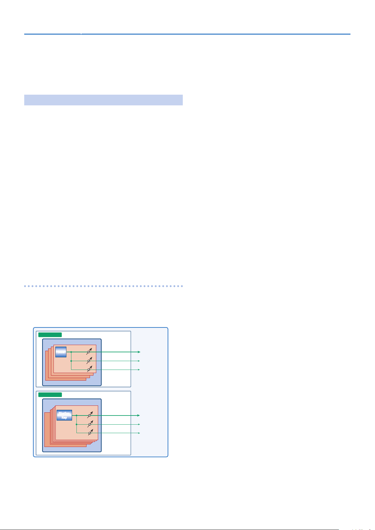
How effects are handled
The multi-effects, chorus and reverb effects can be set up individually for
each patch/rhythm set.
Adjusting the signal level to be sent to each effects unit (Send Level)
provides control over the effect intensity that’s applied to each tone.
Patch
Multi
Effects
Chorus
Reverb
Multi
Effects
Chorus
Reverb
Rhythm Set
Tone
Rhythm
Key
7
Memory and Bank
What is a Memory?
Each of the SRX STUDIO’s sounds is called a “memory.” A memory can be
either a “patch” or a “rhythm set.”
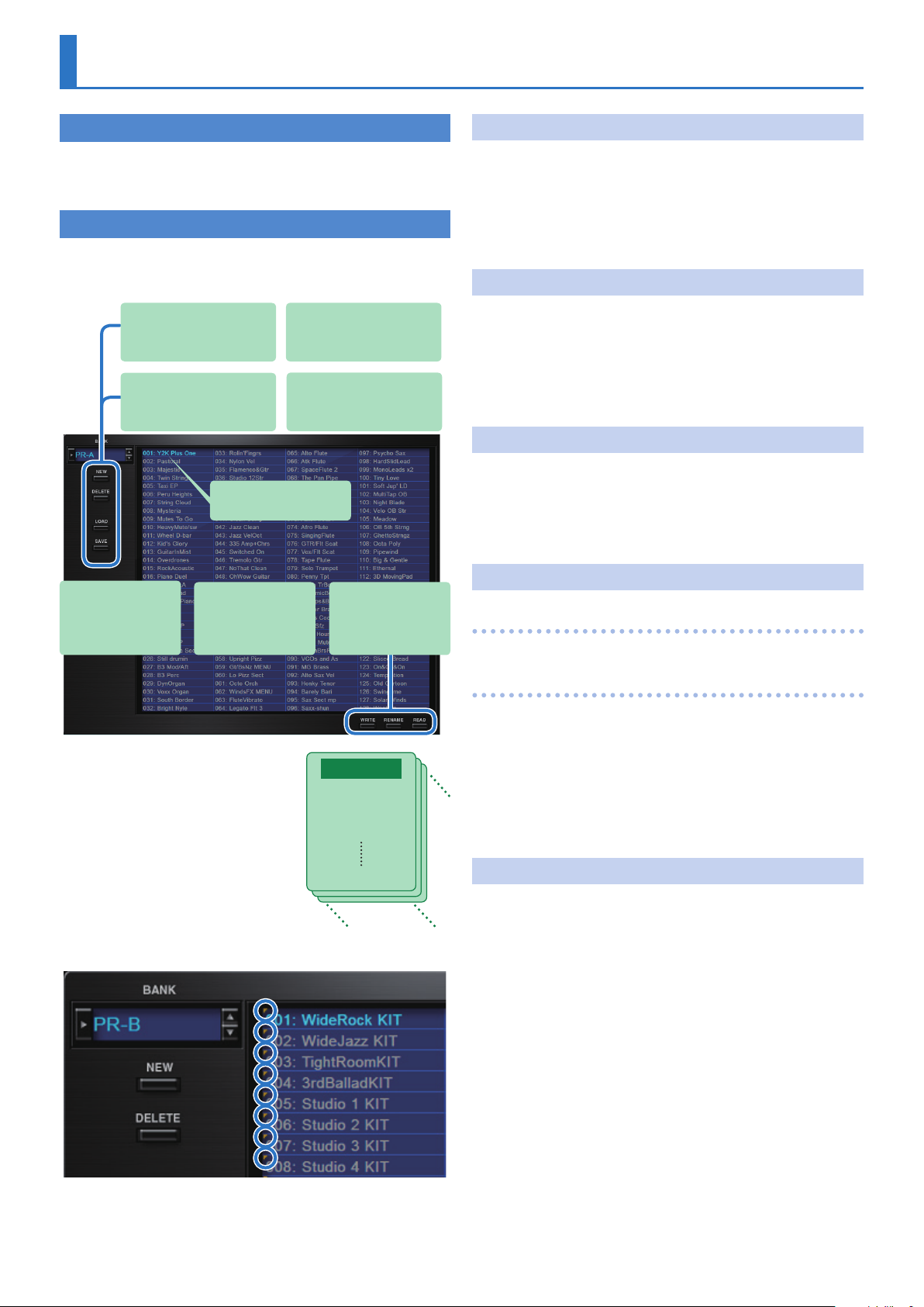
Bank
1. Click the [BANK] button.
The Memory Select screen (BANK) appears.
[NEW] button
Creates a new empty bank.
[LOAD] button
Loads a bank from a file.
[WRITE] button
Saves an edited sound as
a memory in the bank.
The selected memory is
shown in blue.
[RENAME] button
Renames the selected
memory.
[DELETE] button
Deletes the selected bank.
[SAVE] button
Exports a bank as a file.
[READ] button
Loads a memory from
a bank.
Changing to Other Bank
1. Click the Bank field.
The bank list window opens.
2. Click the bank that you want to recall.
By pressing the [H] [I] buttons located at the right of the bank field,
you can switch to the next or previous bank.
Exporting the Bank
Here’s how to export a bank as a file.
1. Click the [SAVE] button.
The file name input window opens.
2. Enter a file name and save.
The file is exported.
Importing a Bank
1. Click the [LOAD] button.
The file selection window opens.
2. Select a file and load it.
The bank is loaded.
Creating/Deleting a Bank
Creating a bank
A set of 128 memories is called a “bank.”
By switching banks you can access a
large number of memories.
A bank of memories can be saved as a
file.
Memory 01
Memory 02
Memory 03
Memory 128
Rhythm Sets have a small symbol at their upper left.
Bank
Click the [NEW] button to create a new empty bank.
Deleting a bank
Here’s how to delete the selected bank.
1. Select a bank as described in “Changing to Other
Bank” (p. 8).
2. Click the [DELETE] button.
A confirmation screen appears.
3. Click [OK] to delete the bank.
Renaming a Bank
1. Select a bank as described in “Changing to Other
Bank” (p. 8).
2. Click J located at the left of the bank field.
3. Edit the name and press the [Return (Enter)] key.
8
Memory and BankSRX STUDIO Software Synthesizer Owner’s Manual
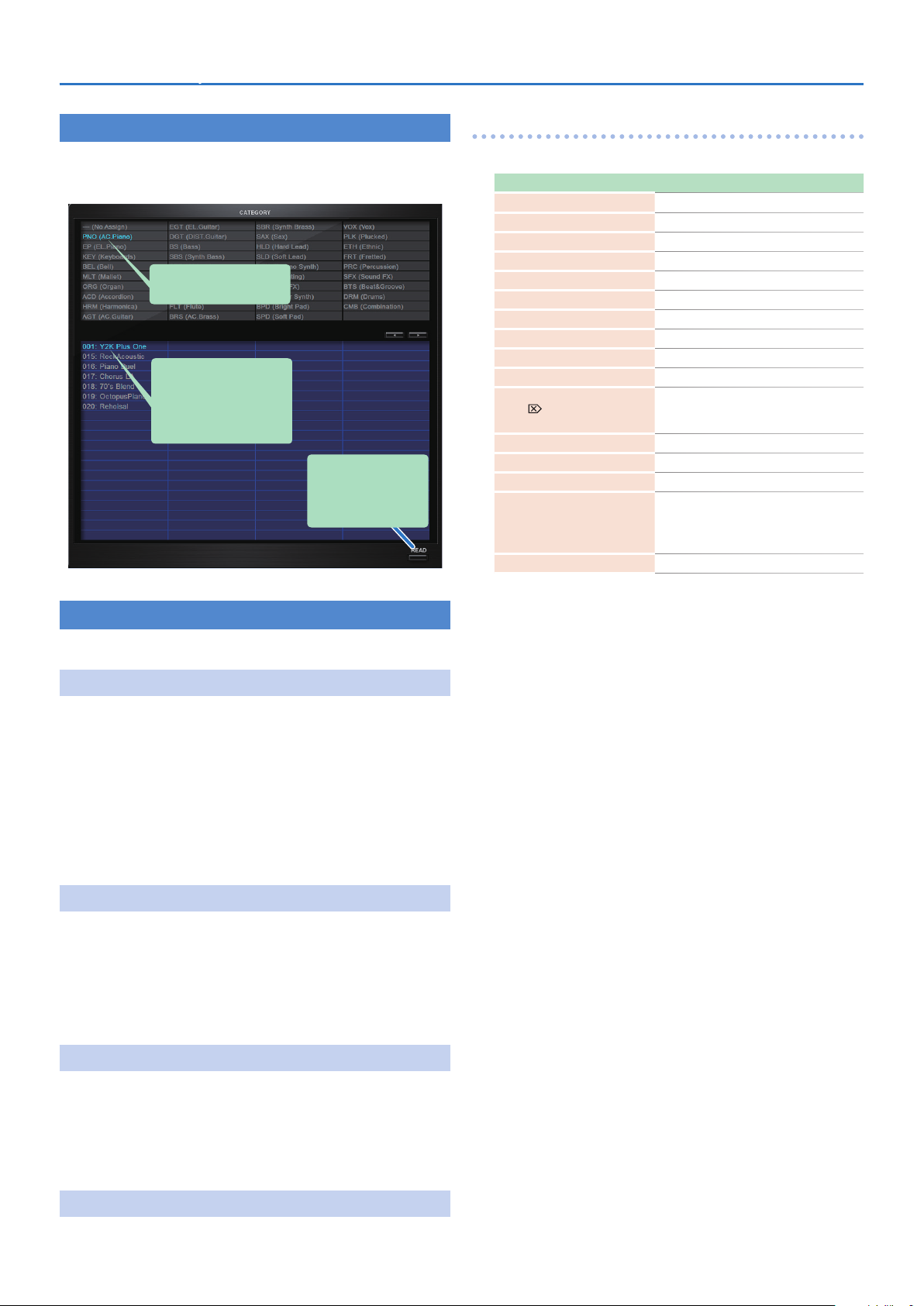
Category
1. Click the [CATEGORY] button.
Memory Select screen (CATEGORY) appears.
The selected category is
shown in blue.
The memory belonging to the
selected category is shown
in the list.
The selected memory is
shown in blue.
[READ] button
Loads a memory from a
category.
Keyboard shortcuts
Keyboard shortcuts for the Patch Select window.
Key Function
Command
Command
Command
Command
Command
Command
Up/Down/Left/Right
Space
Command
Command
Delete *1
delete
fn + delete *2
Return
Command
Command (Ctrl) + Shift + Z
Command
Esc
(Ctrl) + B
(Ctrl) + I
(Ctrl) + E
(Ctrl) + N
(Ctrl) + O
(Ctrl) + S
(Ctrl) + C
(Ctrl) + V
*2
(Enter)
(Ctrl) + Z
(Ctrl) + J
Changes bank
Imports bank
Exports bank
New memory
Loads memory
Saves memory
Selects memory
Renames memory
Copies memory
Pastes memory
Deletes memory
Loads memory
Undo
Redo
Switches the memory number indication
5 001–128
5 01-1–01-8, 02-1–...–16-8
5 A-1–A-8, B-1–...–P-8
Closes window
Memory
The SRX STUDIO manages 128 memories as one bank.
Loading a Memory
Here’s how to load a memory from a bank. When you load a memory, its
settings appear in the edit area and can be edited.
1. Click the number of the memory that you want to load.
2. Click the [READ] button. Or press the [Return (Enter)]
key.
The memory is loaded.
* You can also load a memory by double-clicking a memory
number.
Saving the Memory
Here’s how to save an edited sound as a memory in the bank.
1. Click the number of the memory in which you want to
save the sound.
2. Click the [WRITE] button.
The memory is saved in the bank.
*1 Windows / *2 Mac
Renaming the Memory
1. Click the number of the memory that you want to
rename.
2. Click the [RENAME] button.
3. Change the memory name. (Up to 16 letters)
Changing the Order of the Memories
Drag the memory number to change the order of memories.
9
Settings
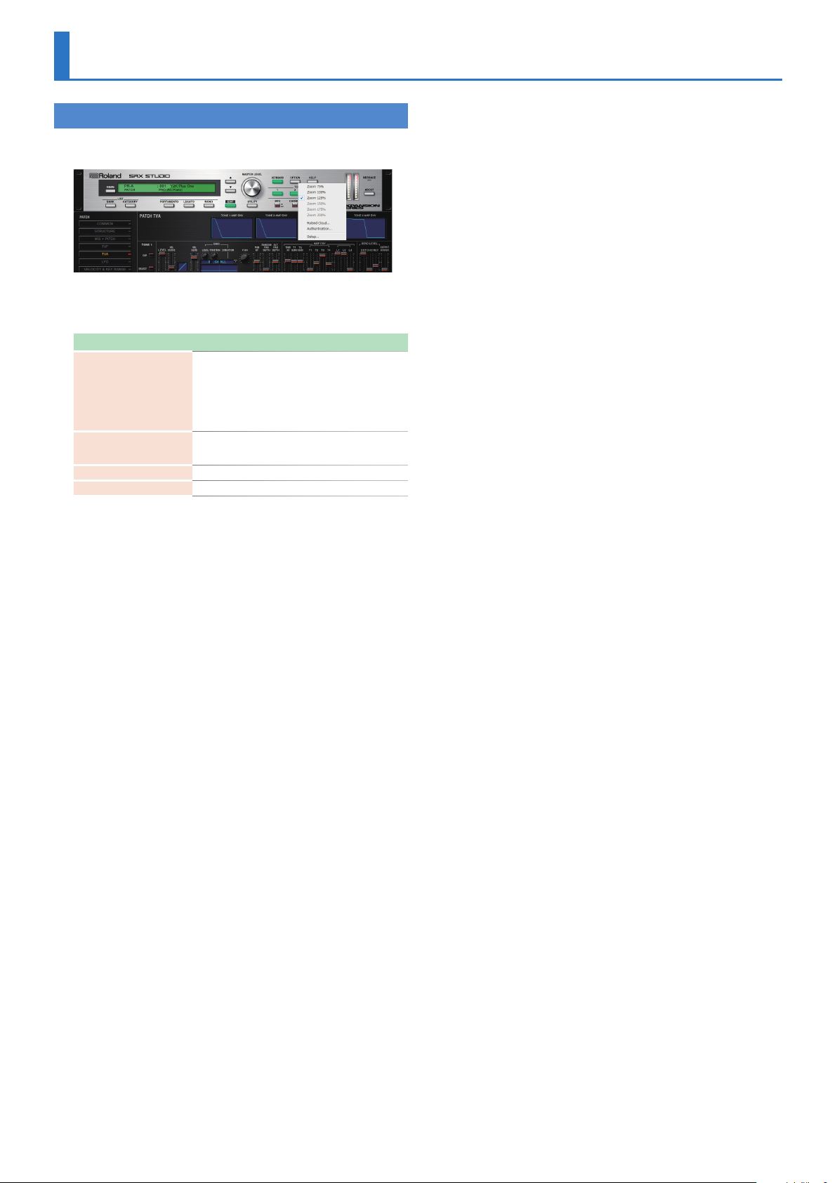
Option
1. Click the [OPTION] button.
2. Select items.
A ( is shown for the selected item.
Item Explanation
Zoom 75%
Zoom 100%
Zoom 125%
Zoom 150%
Zoom 175%
Zoom 200%
Flip Scroll Direction
(Only on Mac)
Roland Cloud... Displays the Roland Cloud site.
Authentication... Performs user authentication for the SRX STUDIO.
Changes the size of the main window.
Inverts the direction of rotation when using the mouse
wheel to edit a value.
10
Detailed Editing for a Patch (PATCH Parameters)
“Editing” is the process of modifying the values of the SRX STUDIO’s
various settings (parameters). This chapter explains the procedure for
patch editing, and how the patch parameters work.
How to Edit a Patch
You can create a new patch by editing an existing patch.
A patch consists of up to four “tones.” Before editing a patch, you
should listen to each tone individually to familiarize yourself with the
role it plays in creating the overall sound of the patch.
Copying/Pasting Patch Parameters
You can select and copy a portion of the patch parameters (such as a patch
tone or MFX), and then paste those parameters to another patch tone or
another patch. You can also initialize the settings of a patch or rhythm set.
TONE SWITCH/SELECT
Use TONE SWITCH (SW) 1–4 to turn each of the four tones on/off.
Use TONE SELECT 1–4 to select the tone that you want to edit.
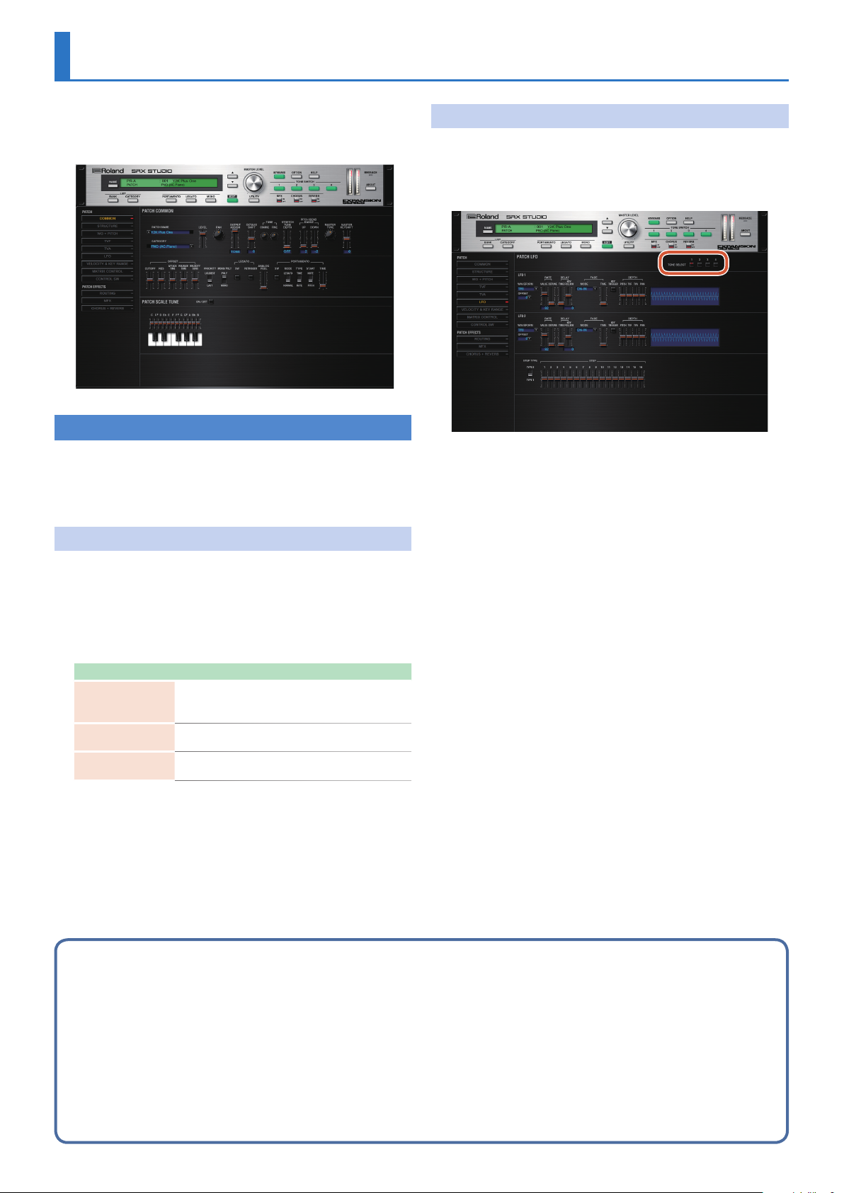
[LFO] editing screen
5 The parameter window will show the settings of the first
selected of the currently selected tones (the button is lit red.).
5 You can select multiple tones by clicking a TONE SELECT button
while holding down the computer’s Shift key.
5 You can select all tones by clicking a TONE SELECT button while
holding down the computer's Command (Ctrl) key.
5 When you edit the settings of a tone, the settings of the
currently selected tones will change simultaneously.
1. In the main window, click the [UTILITY] button.
A popup appears.
Item Explanation
Initialize
Copy
Paste
Initializes the settings of the patch or rhythm set.
This is convenient when you want to create data from
scratch.
Copies the selected parameters from the currently selected
patch or rhythm set to the clipboard.
Pastes the selected parameter from the clipboard to the
current patch or rhythm set.
2. Select “Initialize”, “Copy” or “Paste.”
A list of the items that can be initialized or copied, or a list of the
destinations to which data can be written, appears.
3. In the list, click to select the desired item.
Four tips when creating patches
7 Choose a patch that’s close to what you have in mind
If you’re trying to create a new patch, it will be difficult to make progress if you simply select any old patch and start making changes blindly.
It’s important to start by selecting a patch that’s close to what you have in mind.
7 Decide which tones you’ll use
When creating a patch, it’s very important to decide which tones you’re going to use. In the edit screen, use the TONE SWITCH 1–4 settings to specify whether each tone will be heard
(on) or silent (off). Turning off unneeded tones is also an important way to conserve polyphony.
7 Check the structure setting (p. 15)
The STRUCTURE parameter is a very important one; it specifies how the four tones will be combined. Before you begin actually editing the tones, you must understand the
relationship between the tones.
7 Turn the effects off (p. 34)
The SRX STUDIO contains a diverse array of effects, allowing you to process the sound in sophisticated ways. Effects have a major impact on the sound, and simply turning off the
effects may produce an entirely different impression. Turning off the effects will allow you to hear the sound of the patch itself, which makes it easier to hear the result of the changes
you make. In some cases, editing the effect settings may be enough to create the sound you want.
11
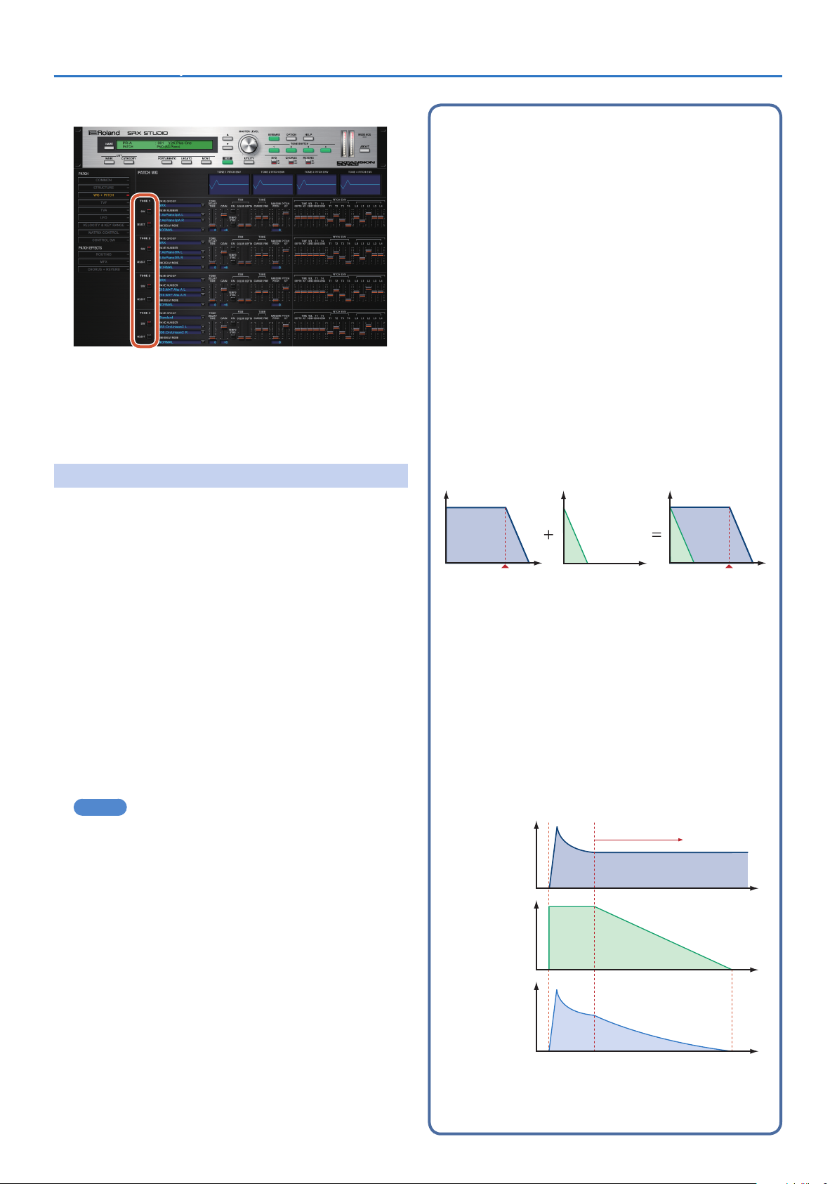
[WG+PITCH], [TVF], [TVA], [CONTROL SW] editing screens
5 You can select multiple tones by clicking a TONE SELECT button
while holding down the computer’s Shift key.
5 When you edit the settings of a tone, the settings of the
currently selected tones will change simultaneously.
5 Unselected tones can be edited independently.
Detailed Editing for a Patch (PATCH Parameters)SRX STUDIO Software Synthesizer Owner’s Manual
Note when selecting a waveform
The SRX STUDIO uses complex PCM waveforms as the basis for its
sounds. For this reason, you should be aware that if you specify
a waveform that is very different than the original waveform, the
result may not be what you expect.
The SRX STUDIO’s internal waveforms can be categorized into the
following two types.
One-shot:
These are sounds with a short decay time. One-shot waveforms contain
the entire duration of the sound from the attack until it decays to silence.
Some of these waveforms capture a complete sound such as a percussion
instrument, but there are also many attack component sounds such as the
hammer strike of a piano or the fret noise of a guitar.
Loop:
These are sounds with a long decay, or sustaining sounds.
Looped waveforms will repeatedly play a portion of a sound once it has
reached a relatively stable state. These sounds also include numerous
component sounds, such as a vibrating piano string or a resonating pipe.
The following illustration shows an example of a sound created
by combining a one-shot waveform with a loop waveform. (This
example is of an electric organ.)
Stereo Wave Settings (Set Stereo Function)
Some of the waves that make up a tone key are stereo.
With stereo waves, the name of a left-channel wave ends in “L” , while
the name of a right-channel wave ends in “R.”
The left and right waves are numbered consecutively; the right-channel
wave number is one greater than the left-channel wave number.
You can use the following procedure to first select either the left or
right wave, and then select the other wave.
1. Select a patch.
2. Make sure that “WG+PITCH” is selected in the “PATCH”
area of the navigation window.
3. Use WAVE NUMBER L to select the left-channel wave of
the stereo wave.
4. While holding down the Command (Ctrl) key, click on
WAVE NUMBER R.
The corresponding right-channel wave will be selected.
MEMO
After selecting the right-channel wave in WAVE NUMBER R, you
can also hold down the Command (Ctrl) key and click on WAVE
NUMBER L to select the left-channel wave.
If the wave is not a stereo wave, the selection won't change.
TVA ENV for looped Organ
waveform (sustain portion)
Level
Note off
TVA ENV for one-shot Key -click
waveform (attack portion)
Time
Resulting TVA ENV
change
Note off
Note when selecting a one-shot waveform
It’s not possible to use the envelope settings to give a one-shot waveform
a longer decay than the original waveform contains, or to make it a
sustaining sound. Even if you made this type of envelope setting, you
would be trying to bring out something that doesn’t exist in the original
waveform.
Note when selecting a looped waveform
Many acoustic instruments such as piano or sax are marked by a sudden
change in timbre at the very beginning of the sound, and this rapid
change is what gives the instrument its distinctive character. When
using these waveforms, it’s best to use the complex tonal changes in the
attack portion of the sound without attempting to modify them; use the
envelope only to modify the decay portion of the sound as desired. If you
use the envelope to modify the attack as well, the envelope settings will
be affected by the attack of the waveform itself, and you may not get the
result you intend.
Level
Tone change
stored with
the wave
Looped portion
Time
12
Envelope for the
TVF filter
Resulting tone
change
Detailed Editing for a Patch (PATCH Parameters)SRX STUDIO Software Synthesizer Owner’s Manual
PATCH Parameters
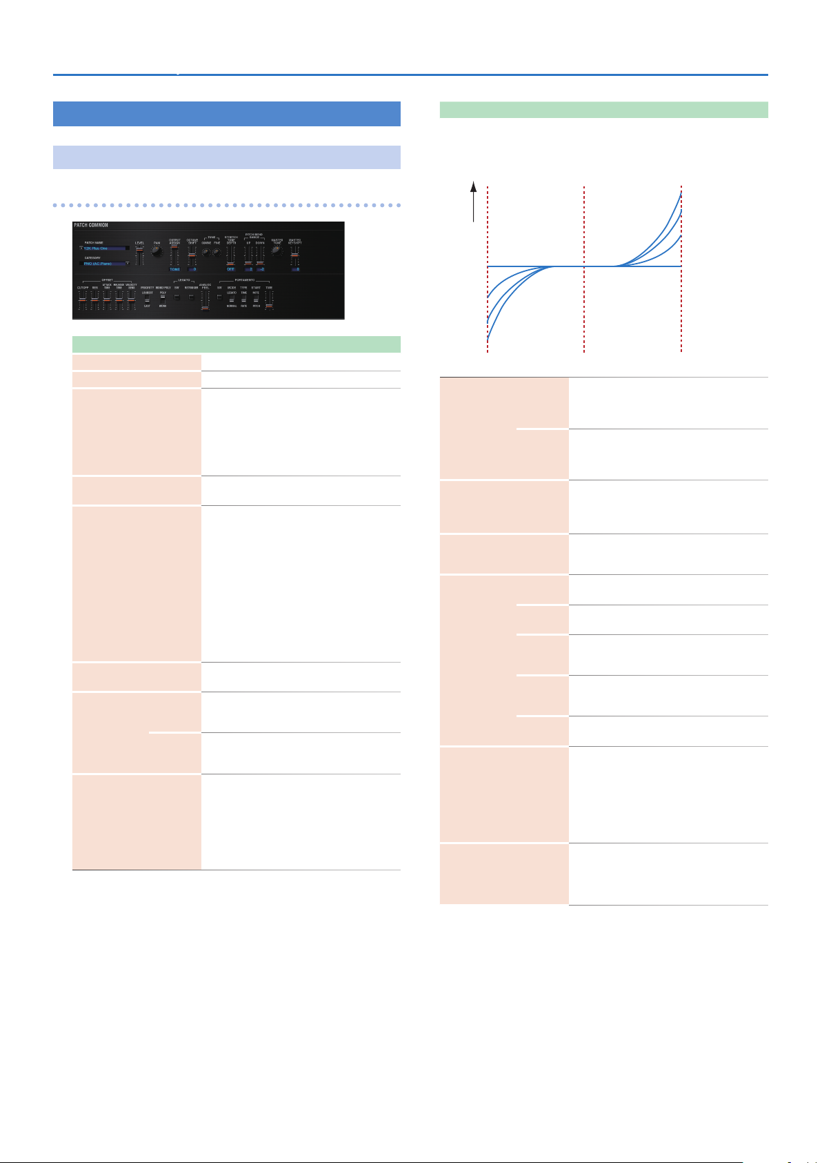
COMMON
PATCH COMMON
Parameter Range/Explanation
PATCH NAME
CATEGORY
LEVEL
PAN
OUTPUT ASSIGN
OCTAVE SHIFT
COARSE
TUNE
FINE
STRETCH TUNE DEPTH
Patch name
Type (category) of the patch
0–127
Volume before passing through MFX/Reverb/
Chorus
For distortion-type effects, the tonal character
changes depending on the volume that is input.
As appropriate for your purpose, adjust this in
conjunction with the [MASTER LEVEL] knob.
L64–0–63R
Left/right position of the patch
Specifies how the direct sound of each patch will
be output.
MFX: Output in stereo through multi-effects. You
can also apply chorus or reverb to the sound that
passes through multi-effects.
L+R: Output in stereo to the OUTPUT
passing through the multi-effect
L: Output in mono to the OUTPUT L without
passing through the multi-effect
R: Output in mono to the OUTPUT R without
passing through the multi-effect
TONE: Outputs according to the settings for each
tone.
-3–3
Pitch of the patch’s sound (in units of an oc tave)
-48–48
Pitch of the patch’s sound (in semitones, +/- 4
octaves)
-50–50
Pitch of the patch’s sound (in 1- cent steps; one cent
is 1/100th of a semitone)
Stretched tuning (a system by which acoustic
pianos are normally tuned, causing the lower range
to be lower and the higher range to be higher than
the mathematical tuning ratios would otherwise
dictate)
OFF: Equal temperament
1–3: Higher settings will produce the greater
difference in the pitch of the low and high ranges.
without
Parameter Range/Explanation
Stretched Tuning
Pitch difference from
equal temperament
OFF
1
2
3
Low note range
0–48
Amount of pitch change (in semitones) that occurs
when the pitch bend controller is at the maximum
position
-48–0
Amount of pitch change (in semitones) that occurs
when the pitch bend controller is at the minimum
position
415.3–466.2 Hz
Overall tuning of the SRX STUDIO
The display shows the frequency of the A4 note
(center A).
-24–+24
Shifts the overall pitch of the SRX STUDIO in
semitone steps.
-63–+63
CUTOFF (p. 19)
-63–+63
RES (p. 19)
-63–+63
TVF Envelope Time 1, TVA Envelope Time 1 (p. 20,
p. 22)
-63–+63
TVF Envelope Time 4, TVA Envelope Time 4 (p. 20,
p. 22)
-63–+63
Cutoff Velocity Sens, TVA Velocity Sens (p. 20, p. 21)
How notes will be managed when the maximum
polyphony is exceeded (128 voices)
LAST: The last-played voices will be given priority
(Notes will be turned off in order, beginning with
the first-played note.)
LOUDEST: The loudest voices will be given priority
(Notes will be turned off, beginning with the
lowest-volume voice.)
MONO: Only the last-played note will sound. This
setting is effective when playing a solo instrument
patch such as sax or flute.
POLY: Two or more notes can be played
simultaneously.
PITCH BEND
RANGE
MASTER TUNE
MASTER KEY SHIFT
OFFSET
PRIORITY
MONO/POLY
UP
DOWN
CUTOFF
RES
ATTACK
TIME
RELEASE
TIME
VELOCITY
SENS
Parameter value
3
2
1
OFF
High note range
13
Detailed Editing for a Patch (PATCH Parameters)SRX STUDIO Software Synthesizer Owner’s Manual
Parameter Range/Explanation
This setting specifies whether the Legato Switch
will be used (ON) or not (OFF).
LEGATO SW is valid when the Mono/Poly parameter
is set to “MONO.”
With the LEGATO SW “ON,” pressing a key while
continuing to press a previous key causes the note
to change pitch to the pitch of the most recently
pressed key, sounding all the while.
This creates a smooth transition between notes,
which is effective when you wish to simulate the
hammering-on and pulling-off techniques used by
a guitarist.
The setting determines whether sounds are
replayed (ON) or not (OFF) when performing
legato. Normally you will leave this parameter
“ON.”
The LEGATO RETRIGGER is valid when the Mono/
Poly is set to “MONO” and the LEGATO SW is set
to “ON.”
When “OFF,” when one key is held down and
another key is then pressed, only the pitch
changes, without the attack of the latter key being
played.
Set this to “OFF” when performing wind and string
phrases or when using modulation with the mono
synth keyboard sound.
0–127
Depth of 1/f modulation (a pleasant and naturally-
occurring ratio of modulation that occurs in a
babbling brook or rustling wind)
* You can simulate the natural instability
characteristic of an analog synthesizer by adding
this “1/f modulation.”
Specifies whether the portamento effect will be
applied (ON) or not (OFF).
Portamento is an effect which smoothly changes
the pitch from the first-played key to the nextplayed key.
NORMAL: Portamento will always be applied.
LEGATO: Portamento will be applied only when
you play legato.
RATE: Speed of pitch change is uniform (the time
required for the pitch change will correspond to
the distance of the pitch change)
TIME: The time it takes will be constant, regardless
of how far apart in pitch the notes are.
PITCH: Start a new portamento from present pitch
when another key is pressed while the pitch is
changing.
NOTE: Portamento will begin anew from the pitch
where the current change would end.
0–127
Specifies the time over which the pitch will change.
LEGATO
(*1)
ANALOG FEEL
PORTAMENTO
SW
RETRIGGER
SW
MODE
TYPE
START
TIME
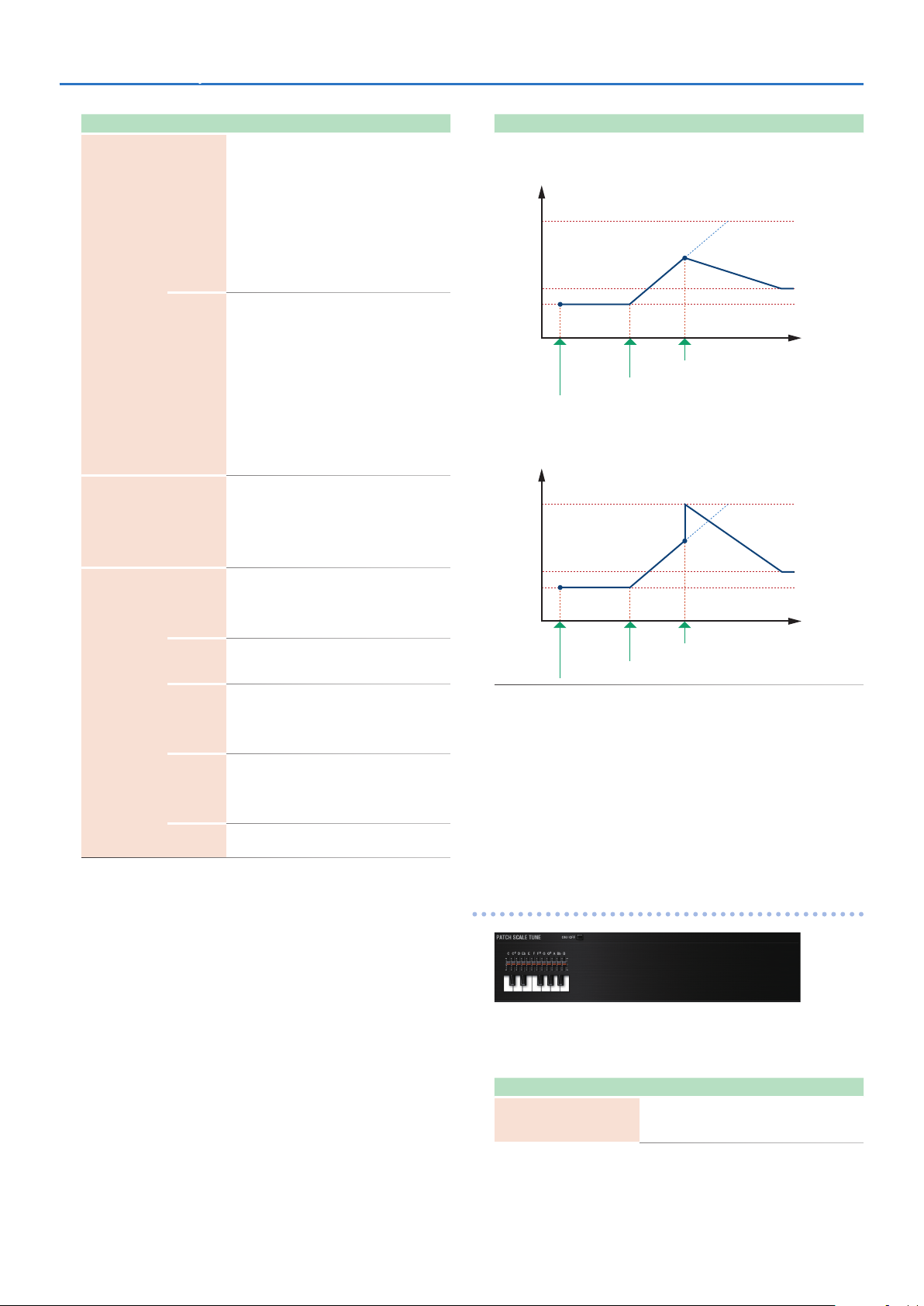
Parameter Range/Explanation
Portamento Start: PITCH
Pitch
C5
D4
C4
Time
press D4 key
press C5 key
press C4 key
Portamento Start: NOTE
Pitch
C5
D4
C4
Time
press D4 key
press C5 key
press C4 key
*1 Let’s say you have the LEGATO SW set to “ON,” and the LEGATO
RETRIGGER set to “OFF.” When you try to sound a legato (by
pressing a higher key while a lower key is held down), the pitch
may sometimes not be able to rise all the way to the intended
pitch (stopping instead at an intermediate pitch). This can occur
because the limit of pitch rise, as determined on each wave form.
Additionally, if differing upper pitch limits are used for the waves of
a Patch that uses multiple tones, it may not being heard as MONO.
When making large pitch changes, set the LEGATO RETRIGGER to
“ON.”
PATCH SCALE TUNE
The SRX STUDIO allows you to play the keyboard using temperaments
other than equal temperament. The pitch is specified in one-cent units
relative to the equal tempered pitch. One-cent is 1/100th of a semitone.
Parameter Range/Explanation
SCALE TUNE
SWITCH
14
OFF, ON
Turn this on when you wish to use a tuning scale
other than equal temperament.
Detailed Editing for a Patch (PATCH Parameters)SRX STUDIO Software Synthesizer Owner’s Manual
Parameter Range/Explanation
C–B
-64–+63
Make scale tune settings for Patch mode.
Equal Temperament
This tuning divides the octave into 12 equal parts, and is the
most widely used method of temperament used in Western
music. The SRX STUDIO employs equal temperament when the
Scale Tune Switch is set to “OFF.”
Just Intonation (Tonic of C)
Compared with equal temperament, the principle triads sound
pure in this tuning. However, this effect is achieved only in one
key, and the triads will become ambiguous if you transpose.
Arabian Scale
In this scale, E and B are a quarter note lower and C#, F# and G#
are a quarter-note higher compared to equal temperament. The
intervals between G and B, C and E, F and G#, Bb and C#, and Eb
and F# have a neutral third-the interval between a major third
and a minor third. On the SRX STUDIO, you can use Arabian
temperament in the three keys of G, C and F.
Note name
C
C#
D
Eb
E
F
F#
G
G#
A
Bb
B
Equal
temperament
0 0 -6
0 -8 +45
0 +4 -2
0 +16 -12
0 -14 -51
0 -2 -8
0 -10 +43
0 +2 -4
0 +14 +47
0 -16 0
0 +14 -10
0 -12 -49
Just intonation
(tonic C)
Arabian scale
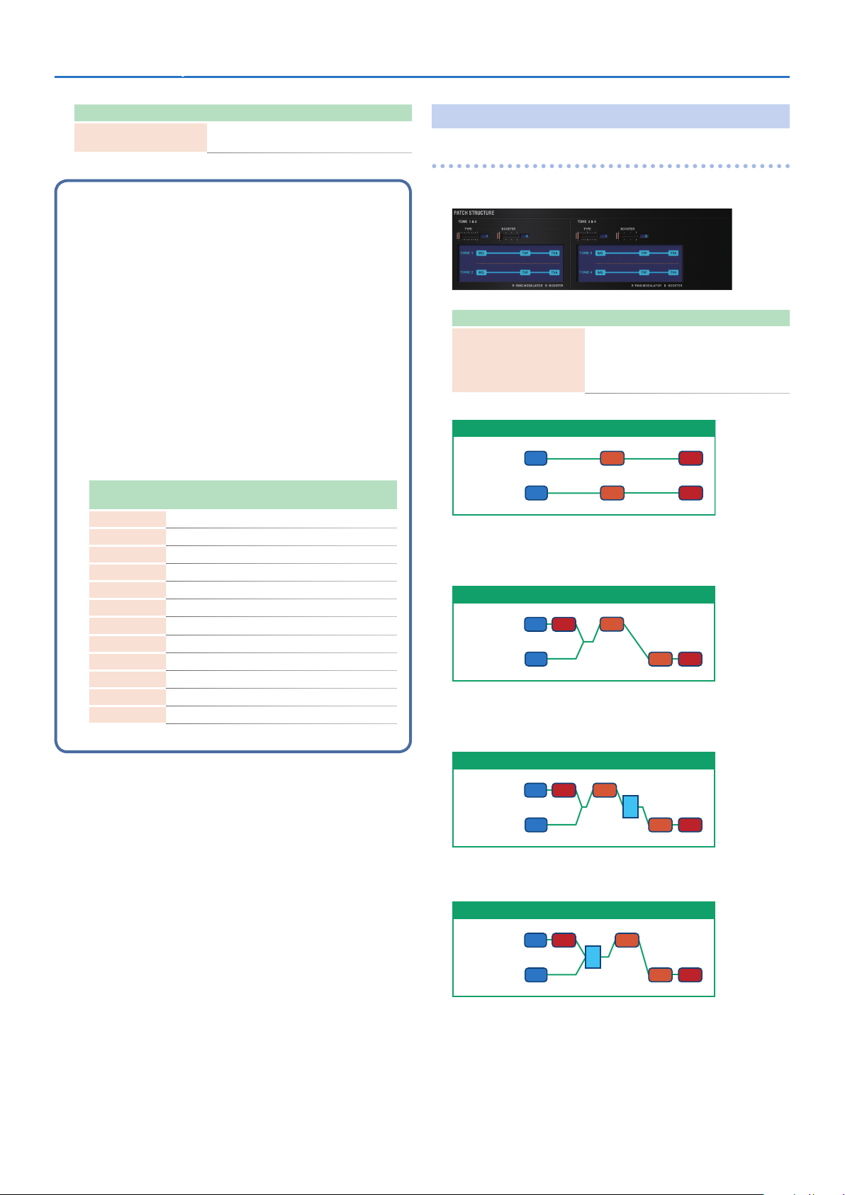
STRUCTURE
PATCH STRUCTURE
Structure changes how a tone is sounded.
Parameter Range/Explanation
1–10
Determines how tone 1 and 2, or tone 3 and 4 are
TONE 1 & 2, 3 & 4 TYPE
Type 01
TONE 1 (3)
TONE 2 (4)
WG
WG
With this type, tones 1 and 2 (or 3 and 4) are independent. Use this type
when you want to preserve PCM sounds or create and combine sounds
for each tone.
Type 02
TONE 1 (3)
TONE 2 (4)
WG
WG
This type stacks the two filters together to intensify the characteristics
of the filters. The TVA for tone 1 (or 3) controls the volume balance
between the two tones.
Type 03
connected.
The following 10 different Types of combination
are available.
TVATVF
TVF TVA
TVA
TVF
TVF TVA
TONE 1 (3)
TONE 2 (4)
WG
WG
TVA TVF
B
TVF TVA
This type mixes the sound of tone 1 (3) and tone 2 (4), applies a filter,
and then applies a booster to distort the waveform.
Type 04
TONE 1 (3)
TONE 2 (4)
WG
TVA TVF
WG
B
TVF TVA
This type applies a booster to distort the waveform, and then combines
the two filters. The TVA for tone 1 (or 3) controls the volume balance
between the two tones and adjusts booster level.
15
Detailed Editing for a Patch (PATCH Parameters)SRX STUDIO Software Synthesizer Owner’s Manual
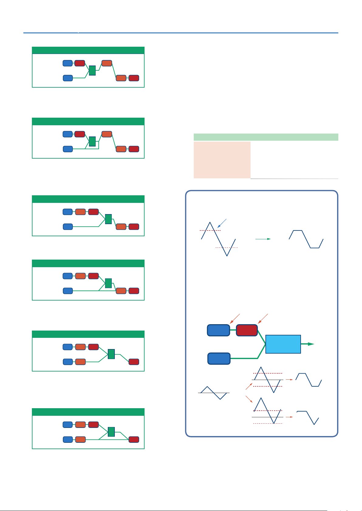
Type 05
TONE 1 (3)
TONE 2 (4)
WG
TVA TVF
WG
R
TVF TVA
This type uses a ring modulator to create new overtones, and combines
the two filters. The tone 1 (3) T VA will control the volume balance of the
two tones, adjusting the depth of ring modulator.
Type 06
TONE 1 (3)
TONE 2 (4)
WG
TVA TVF
WG
R
TVF TVA
This type uses a ring modulator to create new overtones, and in
addition mixes in the sound of tone 2 (4) and stacks the two filters.
Since the ring-modulated sound can be mixed with tone 2 (4), tone 1
(3) TVA can adjust the amount of the ring-modulated sound.
Type 07
TONE 1 (3)
TONE 2 (4)
WG
WG
TVATVF
R
TVF TVA
* When TYPE 02–10 is selected and one tone of a pair is turned
off, the other tone will be sounded as TYPE 01 regardless of the
displayed setting.
* If you limit the keyboard area in which a tone will sound (KEY
RANGE, p. 25) or limit the range of velocities for which it will
sound (VELOCITY RANGE, p. 25), the result in areas or ranges
where the tone does not sound is just as if the tone had been
turned off. This means that if TYPE 02–10 is selected and you
create a keyboard area or velocity range in which one tone of
a pair does not sound, notes played in that area or range will
be sounded by the other tone as TYPE 01 regardless of the
displayed setting.
Parameter Range/Explanation
0, +6, +12, +18
Specifies the amount of boost that is applied (when
TONE 1 & 2, 3 & 4
BOOSTER
the Structure Type is 03 or 04)
The booster distorts the sound by boosting the
input signal, producing the distortion effect that is
often used with an electric guitar. Increasing this
value will produce stronger distortion.
Booster
The Booster is used to distort the incoming signal.
Booster level
This type applies a filter to tone 1 (3) and ring-modulates it with tone 2
(4) to create new overtones.
Type 08
TONE 1 (3)
TONE 2 (4)
WG
WG
TVATVF
R
TVF TVA
This type sends the filtered tone 1 (3) and tone 2 (4) through a ring
modulator, and then mixes in the sound of tone 2 (4) and applies a filter
to the result.
Type 09
TONE 1 (3)
TONE 2 (4)
WG
WG
TVATVF
TVF TVA
R
This type passes the filtered sound of each tone through a ring
modulator to create new overtones. The tone 1 (3) TVA will control
the volume balance of the two tones, adjusting the depth of ring
modulator.
Type 10
In addition to using this other than to create distortion, you can
use the waveform (WG1) of one of the tones as an LFO which
shifts the other waveform (WG2) upward or downward to create
modulation similar to PWM (pulse width modulation).
This parameter works best when you use it in conjunction with
the WAVE GAIN parameter (p. 18).
Uses WG1 as LFO Adjusts WG1 output
TVAWG1
Booster
WG2
WG2
Adds to WG1
Distorted area of the
Waveform changes
TONE 1 (3)
TONE 2 (4)
WG
WG
TVATVF
TVF TVA
R
This type passes the filtered sound of each tone through a ring
modulator to create new overtones, and also mixes in the sound of
tone 2 (4). Since the ring-modulated sound can be mixed with tone 2
(4), tone 1 (3) TVA can adjust the amount of the ring-modulated sound.
Shift in waveform by WG1
16
Ring Modulator
A ring modulator multiplies the waveforms of two tones with each
other, generating many new overtones (inharmonic partials) which
were not present in either waveform (Unless one of the waveforms
is a sine wave, evenly-spaced frequency components will not usually
be generated.).
As the pitch difference between the two waveforms changes the
harmonic structure, the result will be an unpitched metallic sound.
This function is suitable for creating metallic sounds such as bells.
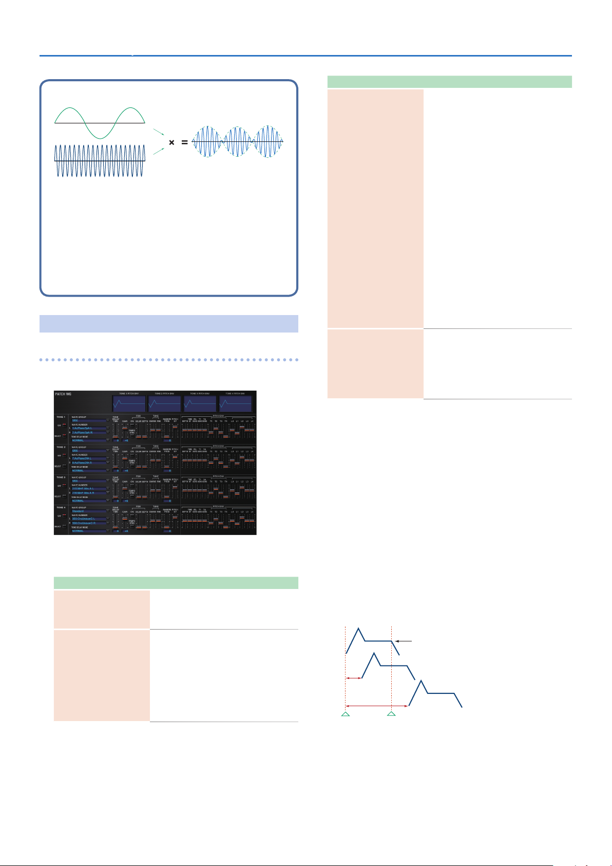
WG + PITCH
PATCH WG
This modifies Waveforms/Pitch Envelope.
Detailed Editing for a Patch (PATCH Parameters)SRX STUDIO Software Synthesizer Owner’s Manual
Parameter Range/Explanation
Type of tone delay
NORMAL: The tone begins to play after the time
specified in the TONE DELAY TIME parameter has
elapsed.
HOLD: Although the tone begins to play after the
time specified in the TONE DELAY TIME parameter
has elapsed, if the key is released before the time
specified in the TONE DELAY TIME parameter has
elapsed, the tone is not played.
KEY-OFF-NORMAL: Rather than being played
while the key is pressed, the tone begins to play
once the period of time specified in the TONE
DELAY TIME parameter has elapsed after release
TONE DELAY MODE
(*1)
TONE DELAY TIME
(*1)
of the key. This is effective in situations such as
when simulating noises from guitars and other
instruments.
KEY-OFF-DECAY: Rather than being played while
the key is pressed, the tone begins to play once
the period of time specified in the TONE DELAY
TIME parameter has elapsed after release of the
key. Here, however, changes in the TVA Envelope
begin while the key is pressed, which in many
cases means that only the sound from the release
portion of the envelope is heard.
* If you have selected a waveform that is a decay-type
sound (i.e., a sound that fades away naturally even
if the key is not released), selecting “KEY-OFF-
NORMAL” or “KEY-OFF-DEC AY” may result in no
sound being heard.
0–127, Note
Time from when the key is pressed (or if the
Tone Delay Mode parameter is set to “KEY-OFF-
NORMAL” or “KEY-OFF-DECAY,” the time from
when the key is released) until when the tone
will sound Specify this as a note value if you want
to synchronize the delay to the tempo of the
SRX STUDIO.
Parameter marked with a “2" can be controlled using specified MIDI
messages (Matrix Control, p. 26).
Parameter Range/Explanation
Selects the group for the waveform that is to be the
Wave Group
WAVE NUMBER
L
(Mono) /R
basis of the tone.
Standard: Basic wave group
SRX: SRX wave group
Off, 1–
Basic waveform for a tone
When in monaural mode, only the left side (L) is
specified. When in stereo, the right side
(R) is also specified.
“Set Stereo function”
To select a left/right pair of waveforms, select
the left (L) WAVE No., and then hold down the
Command (Ctrl) key and click the right (R) WAVE
No. to recall the right (R) WAVE.
*1 This produces a time delay between the moment a key is pressed
(or released), and the moment the tone actually begins to sound.
You can also make settings that shift the timing at which each tone
is sounded. This differs from the Delay in the internal effects, in that
by changing the sound character of the delayed tones and changing
the pitch for each tone, you can also perform arpeggio-like passages
just by pressing one key.
You can also synchronize the tone delay time to the tempo of the
SRX STUDIO.
5 If you are not going to use Tone Delay, set the TONE DELAY
MODE parameter to “NORMAL” and DELAY TIME parameter to
“0.”
5 If STRUCTURE (p. 15) is set to TYPE 02–10, the settings for tone
1 (3) will follow the settings of tone 2 (4). (This is because the
outputs of tones 1 and 2 are combined into tone 2, and the
outputs of tones 3 and 4 are combined into tone 4.)
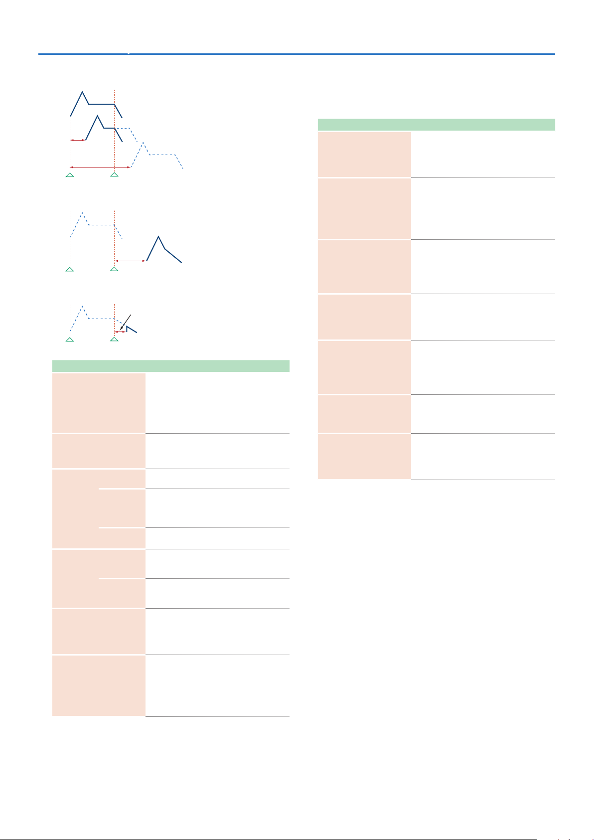
* The following illustration shows the operation of “TVA Env.”
Tone Delay Mode: NORMAL
No Tone Delay
Delay Time
Note on Note off
17
Detailed Editing for a Patch (PATCH Parameters)SRX STUDIO Software Synthesizer Owner’s Manual
Tone Delay Mode: HOLD
No sound
Delay Time
Note on Note off
Tone Delay Mode: KEY-OFF-NORMAL
Delay Time
Note on Note off
Tone Delay Mode: KEY-OFF-DECAY
Note on Note off
Parameter Range/Explanation
GAIN
TEMPO SYNC
ON
FXM
(*2)
TUNE
RANDOM PITCH
PITCH KF
(Pitch Keyfollow)
COLOR
DEPTH 2
COARSE 2
FINE 2
played
Delay Time
-6, 0, +6, +12
Gain (amplification) of the waveform
The value changes in 6 dB (decibel) steps—an
increase of 6 dB doubles the waveform’s gain.
* If you intend to use the Booster to distort the
waveform’s sound, set this parameter to its
maximum value (p. 16).
Turn this “ON” if you want the Phrase Loop to
match the tempo of the DAW.
* When this parameter is set to “ON,” set the TONE
DELAY TIME parameter (p. 17) to “0.”
This sets whether FXM will be used (ON) or not
(OFF).
1–4
How FXM will perform frequency modulation
Higher settings result in a grainier sound, while
lower settings result in a more metallic sound.
0–16
Depth of the modulation produced by FXM
-48–+48
Pitch of the tone’s sound (in semitones, +/-4
octaves)
-50–+50
Pitch of the tone’s sound (in 1-cent steps; one cent
is 1/100th of a semitone)
0–1200
Width of random pitch deviation that will occur
each time a key is pressed (in 1-cent steps)
If you do not want the pitch to change randomly,
set this to “0.”
-200–+200
Amount of pitch change that will occur when you
play a key one octave higher
If you want the pitch to rise one octave as on a
conventional keyboard, set this to “+100.” If you
want the pitch to rise two octaves, set this to
“+200.”
PITCH ENV (WAVE PITCH ENVELOPE)
Parameter marked with a “2" can be controlled using specified MIDI
messages. (Matrix Control, p. 26).
Parameter Range/Explanation
-12–+12
DEPTH
TIME KF
(Time Keyfollow)
VEL SENS
(Velocity Sens)
T1 SENS
(T1 Velocity Sens)
T4 SENS
(T4 Velocity Sens)
T1–4 2
(Time 1–4)
L0–4
(Level 0–4)
Depth of the Pitch envelope
Higher settings will cause the pitch envelope to
produce greater change. Negative (-) settings will
invert the shape of the envelope.
-100–+100
Use this setting if you want the pitch envelope
times (T2–T4) to be affected by the keyboard
location.
Based on the pitch envelope times for the C4 key,
positive (+) settings will cause notes higher than C4
to have increasingly shorter times.
-63–+63
Keyboard playing dynamics can be used to control
the depth of the pitch envelope.
If you want the pitch envelope to have more effect
for strongly played notes, set this parameter to a
positive (+) value.
-63–+63
This allows keyboard dynamics to affect the T1 of
the Pitch envelope.
If you want T1 to be speeded up for strongly played
notes, set this parameter to a positive (+) value.
-63–+63
Use this parameter when you want key release
speed to affect the T4 value of the Pitch envelope.
If you want T4 to be speeded up for quickly
released notes, set this parameter to a positive (+)
value.
0–127
Pitch envelope times (T1–T4)
Higher settings will result in a longer time until the
next pitch is reached.
-63–+63
Pitch envelope levels (L0–L4)
Specify how the pitch will change at each point,
relative to the pitch set with COARSE TUNE or FINE
TUNE.
*2 FXM (Frequency Cross Modulation) uses a specified waveform to
apply frequency modulation to the currently selected waveform,
creating complex overtones. This is useful for creating dramatic
sounds or sound effects.
18
Detailed Editing for a Patch (PATCH Parameters)SRX STUDIO Software Synthesizer Owner’s Manual
Pitch Keyfollow
Pitch
C4C3C2C1 C5 C6 C7
Pitch Envelope
T1
T2 T3 T4
Pitch
L0
L1
Note on Note off
L2
+200
L3
+100
+50
0
-50
-100-200
PATCH TVF
A filter cuts or boosts a specific frequency region to change a sound’s
brightness, thickness, or other qualities.
Key
Time
L4
Parameter marked with a “2" can be controlled using specified MIDI
messages (Matrix Control,p. 26).
Parameter Range/Explanation
Type of filter
OFF: No filter is used.
LPF: Low Pass Filter. This reduces the volume of all
frequencies above the Cutoff Frequency in order to
round off, or un-brighten the sound.
BPF: Band Pass Filter. This leaves only the
frequencies in the region of the Cutoff Frequency,
and cuts the rest. This can be useful when creating
distinctive sounds.
HPF: High Pass Filter. This cuts the frequencies
in the region below the Cutoff Frequency.
This is suitable for creating percussive sounds
emphasizing their higher tones.
PKG: Peaking Filter. This emphasizes the
frequencies in the region of the Cutoff Frequency.
FILTER TYPE
CUTOFF 2
(Cutoff Frequency)
RES 2
(Resonance)
RES VEL SENS
(Resonance Velocity Sens)
You can use this to create wah-wah effects by
employing an LFO to change the Cutoff Frequency
cyclically.
LPF2: Low Pass Filter 2. Although frequency
components above the Cutoff Frequency are cut,
the sensitivity of this filter is half that of the LPF.
This filter is good for use with simulated instrument
sounds such as the acoustic piano.
LPF3: Low Pass Filter 3. Although frequency
components above the Cutoff Frequency are cut,
the sensitivity of this filter changes according to
the Cutoff Frequency. While this filter is also good
for use with simulated acoustic instrument sounds,
the nuance it exhibits differs from that of the LPF2,
even with the same TVF Envelope settings.
* If you set “LPF2” or “LPF3,” the setting for the RES
parameter will be ignored.
0–127
Frequency at which the filter begins to have an
effect on the waveform’s frequency components
0–127
Emphasizes the portion of the sound in the region
of the cutoff frequency, adding character to the
sound
* Excessively high settings can produce oscillation,
causing the sound to distort.
-63–+63
This allows keyboard velocity to modify the
amount of Resonance.
If you want strongly played notes to have a greater
Resonance effect, set this parameter to positive
(+) settings.
TVF
19
Detailed Editing for a Patch (PATCH Parameters)SRX STUDIO Software Synthesizer Owner’s Manual
+1
+2
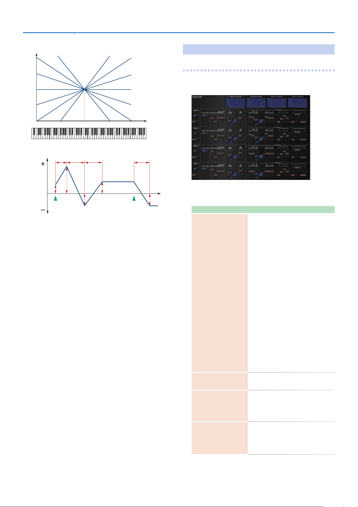
Cutoff Keyfollow
1FIX 2 3 4 5 6 7
1FIX 2 3 4 5 6 7
Parameter Range/Explanation
-200–+200
Use this parameter if you want the cutoff frequency
to change according to the key that is pressed
CUTOFF KF
(Cutoff Keyfollow)
Level
High
Frequency
Cutoff frequency
Parameter Value
Low
Cutoff frequency
(Octave)
o
-1
-2
Parameter Range/Explanation
VEL CURVE
(Cutoff Velocity Curve)
Relative to the cutoff frequency at the C4 key
(center C), positive (+) settings will cause the cutoff
frequency to rise for notes higher than C4, and
negative (-) settings will cause the cutoff frequency
to fall for notes higher than C4. Larger settings will
produce greater change.
Resonance
+200
C4C3C2C1 C5 C6 C7
FIX, 1–7
Curve that determines how keyboard playing
dynamics (velocity) will affect the cutoff frequency
Set this to “FIX” if you don’t want the Cutoff
frequency to be affected by the keyboard velocity.
+100
+50
0
-50
-100-200
Key
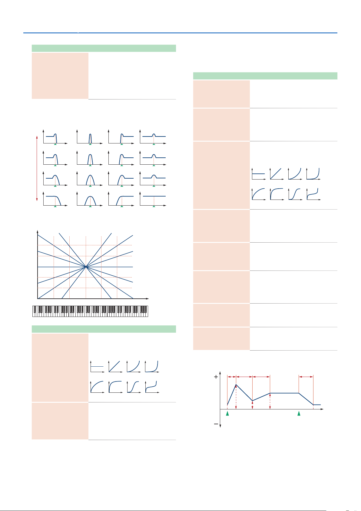
FILTER ENV (TVF ENVELOPE)
Parameter marked with a “2" can be controlled using specified MIDI
messages (Matrix Control, p. 26).
Parameter Range/Explanation
-63–+63
DEPTH
PKGHPFBPFLPF
TIME KF
(Time Keyfollow)
VEL CURVE
(Velocity Curve)
VEL SENS
(Velocity Sens)
T1 SENS
T4 SENS
T1–4 2
(Time 1–4)
L0–4
(Level 0–4)
TVF Envelope
T1
Depth of the TVF envelope
Higher settings will cause the TVF envelope to
produce greater change. Negative (-) settings will
invert the shape of the envelope.
-100–+100
Use this setting if you want the TVF envelope times
(T2–T4) to be affected by the keyboard location.
Based on the TVF envelope times for the C4 key
(center C), positive (+) settings will cause notes
higher than C4 to have increasingly shorter times.
FIX, 1–7
Curve that determines how keyboard playing
dynamics (velocity) will affect the TVF envelope Set
this to “FIX” if you don’t want the TVF Envelope to
be affected by the keyboard velocity.
-63–+63
Specifies how keyboard playing dynamics will
affect the depth of the TVF envelope.
Positive (+) settings will cause the TVF envelope to
have a greater effect for strongly played notes, and
negative (-) settings will cause the effect to be less.
-63–+63
This allows keyboard dynamics to affect the T1 of
the TVF envelope.
If you want T1 to be speeded up for strongly played
notes, set this parameter to a positive (+) value.
-63–+63
Use this parameter when you want key release
speed to affect the T4 value of the TVF envelope.
If you want T4 to be speeded up for quickly
released notes, set this parameter to a positive (+)
value.
0–127
TVF envelope times (T1–T4)
Higher settings will lengthen the time until the
next cutoff frequency level is reached.
0–127
TVF envelope levels (L0–L4)
Specify how the cutoff frequency will change at
each point, relative to the Cutoff Frequency value.
T2 T3 T4
Cutoff
-63–+63
VEL SENS
(Cutoff Velocity Sens)
Use this parameter when changing the cutoff
frequency to be applied as a result of changes in
playing velocity.
If you want strongly played notes to raise the
cutoff frequency, set this parameter to positive (+)
settings.
frequency
L0
Note on Note off
L2 L3 L4
L1
Time
20
Detailed Editing for a Patch (PATCH Parameters)SRX STUDIO Software Synthesizer Owner’s Manual
Delay Time Keyfollow
1FIX 2 3 4 5 6 7
Time
TVA
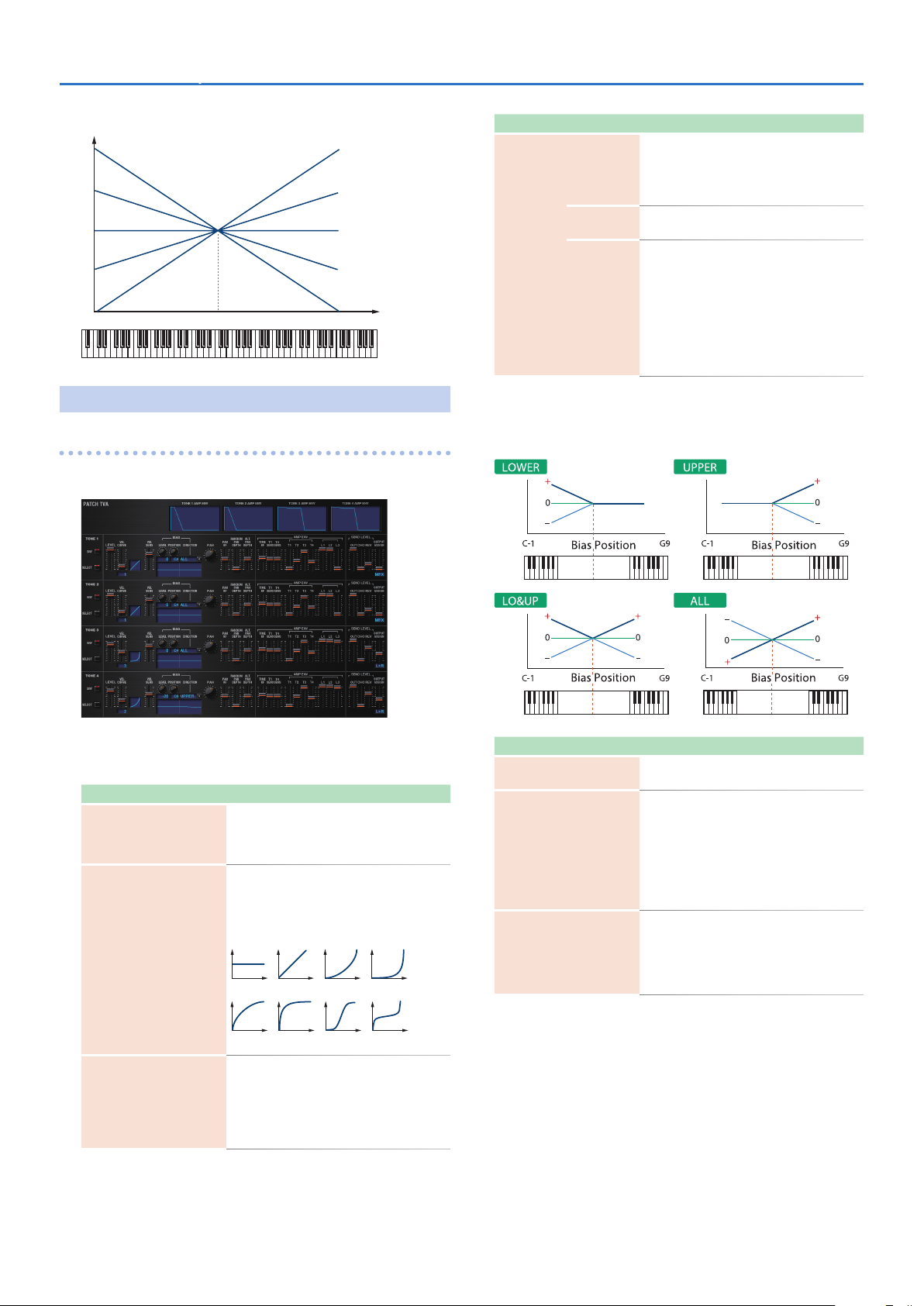
PATCH TVA
TVA adjusts the volume.
C4C3C2C1 C5 C6 C7
-100
-50
0
+50
+100
Key
Parameter Range/Explanation
-100–+100
Angle of the volume change that will occur in the
LEVEL
POSITION
BIAS
(*1)
DIRECTION
selected Bias Direction
Larger settings will produce greater change.
Negative (-) values will invert the change direction.
C-1–G9
Key relative to which the volume will be modified
Direction in which change will occur starting from
the Bias Position
LOWER: The volume will be modified for the
keyboard area below the Bias Position.
UPPER: The volume will be modified for the
keyboard area above the Bias Position.
LO&UP: The volume will be modified symmetrically
toward the left and right of the Bias Position.
ALL: The volume changes linearly with the Bias
Position at the center.
*1 Bias causes the volume to be affected by the keyboard position. This
is useful for changing volume through keyboard position (pitch)
when playing acoustic instruments.
Level
Key
Level
Key
Parameter marked with a “2" can be controlled using specified MIDI
messages (Matrix Control, p. 26).
Parameter Range/Explanation
0–127
LEVEL 2
VEL CURVE
(Velocity Curve)
VEL SENS
(Velocity Sens)
Volume of the tone
This setting is useful primarily for adjusting the
volume balance between tones.
FIX, 1–7
Curve that determines how keyboard playing
dynamics (velocity) will affect the volume
Set this to “FIX” if you don’t want the volume of
the tone to be affected by the keyboard velocity.
-63–+63
Set this when you want the volume of the tone to
change depending on keyboard playing dynamics
Set this to a positive (+) value to have the changes
in tone volume increase the more forcefully the
keys are played; to make the tone play more softly
as you play harder, set this to a negative (-) value.
Level
Parameter Range/Explanation
PAN 2
PAN KF
(Pan Keyfollow)
RANDOM PAN DEPTH
Level
Key
L64–0–63R
Left/right position of the tone
-100–+100
Use this parameter if you want key position to
affect panning.
Positive (+) settings will cause notes higher than
C4 key (center C) to be panned increasingly
further toward the right, and negative (-) settings
will cause notes higher than C4 key (center C) to
be panned toward the left. Larger settings will
produce greater change.
0–63
Use this parameter when you want the stereo
location to change randomly each time you press
a key.
Higher settings will produce a greater amount of
change.
Key
21
 Loading...