

Page 1
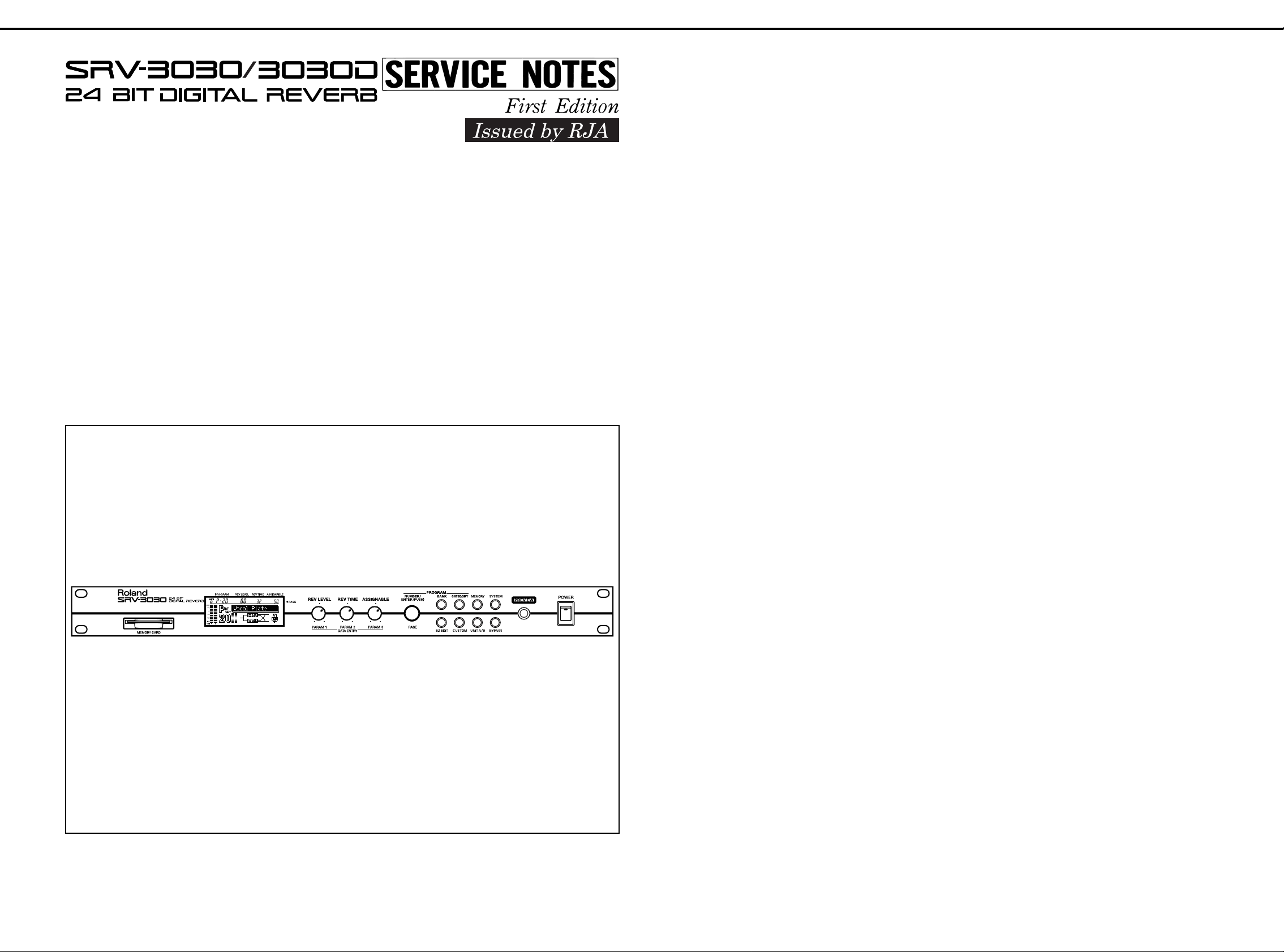
May,1999 SRV-3030/3030D
TABEL OF CONTENTS
SPECIFICATION.....................................................
LOCATION OF CONTROLS ..................................
EXPLODED VIEW ..................................................
BLOCK DIAG R AM .............................. ....................
PARTS LIST............................................................
IDENTIFYING VERSION NUMBER........................
LOADING TH E...................... ..................................
目次
目次 Page
目次目次
主な仕様
パネル配置図
分解図
ブロック図
パーツリスト
バージョンナンバーの確認方法
工場出荷データの復帰方法
FACTRY PRESET DATA
SYSTEM SOFTWARE UPDATE SMF
USING THE SMF..................................................
TEST MODE ................................ .................... .......
ERROR MESSAGE LIST...................................... ..
CIRCUIT DIAGRAM & BOARD...............................
アップデートについて
テストモード
エラーメッセージ一覧
回路図&基板図
Page
PagePage
..................................................... 1~2
............. .................. ............... ....3
............. ....... .... ....... ...... ....... .... ....... ...... 4
.....................................................5
............. .................. ............... 6~7
..................... 7
............................ 7
によるシステムの
............. ................. ..8
............. .................. ............... 8~9
.................................10
...................................... 11~19
SPECIFICATIONS /主な仕様
SRV-3030/SRV-3030D: 24BIT DIGITAL REVERB
• AD Conversion
24 bit 64 times Oversampling
• DA Conversion
24 bit 128 times Oversampling
• Sampling Frequency
SRV-3030 : 44.1 kHz
SRV-3030D : 44.1 k/48 kHz
• Program Memories
Preset : 100
User : 100
• Frequency Response
5 Hz to 200 kHz: −3/+1 dB (direct)
15 Hz to 20 kHz: −3/+1 dB (effect)
• Nominal Input Level
−
20 to +4 dBm
• Input Impedance
20 k ohms (HOT-COLD)
12 k ohms (HOT-GND, COLD-GND)
/主な仕様
/主な仕様/主な仕様
SRV-3030/SRV-3030D:24 BIT
●AD変換
倍オーバーサンプリング
24bit64
●DA変換
24bit+128
●サンプリング周波数
SRV-3030:44.1kHz
SRV-3030D: 44.1k/48kHz
●プログラム・メモリー
プリセット:
ユーザー :
●周波数特性
5 Hz〜200 kHz:
15 Hz〜20 kHz: −3/+1dB
●規定入力レベル
−
20〜+4 dBm
●入力インピーダンス
20 kΩ(HOT-COLD
12 kΩ(HOT-GND、COLD-GND
倍オーバーサンプリング
100
100
−
3/+1dB
)
(ダイレクト)
(エフェクト)
デジタル・リバーブ
)
• Nominal Out put Level
−
20 to +4 dBm
• Output Impedance
640 ohms (HOT-COLD)
320 ohms (HOT-GND, COLD-GND)
• Total Harmonic Distortion
0.01 % or less (direct)
0.02 % or less (effect)
• Dynamic Range
110 dB or greater (direct)
100 dB or greater (effect)
• Controls
REV LEVEL/PARAM 1 Knob
REV TIME/PARAM 2 Knob
ASSIGNABLE/PARAM 3 Knob
NUMBER/PAGE(PUSH ENTER) Knob
BANK Button
CATEGORY Button
MEMORY Button
SYSTEM Button
EZ EDIT Button
CUSTOM Button
UNIT A/B Button
BYPASS Button
PREVIEW Button
POWER Switch
●規定出力レベル
−
20〜+4 dBm
●出力インピーダンス
640 Ω(HOT-COLD
320 Ω(HOT-GND、COLD-GND
●全高調波歪率
以下(ダイレクト)
0.01 %
以下(エフェクト)
0.02 %
●ダイナミック・レンジ
以上(ダイレクト)
110 dB
以上(エフェクト)
100 dB
●コントロール
REV LEVEL/PARAM 1
REV TIME/PARAM 2
ASSIGNABLE/PARAM 3
NUMBER/PAGE
ボタン、
BANK
SYSTEM
UNIT A/B
電源スイッチ
ボタン、
ボタン、
)
つまみ
つまみ
つまみ
つまみ(
CATEGORY
PUSH ENTE R
EZ EDIT
BYPASS
)
ボタン、
ボタン、
ボタン、
)
MEMORY
CUSTOM
PREVIEW
ボタン
ボタン
ボタン
Copyright 1999 ROLAND CORPORATION
All rights reserved. No part of this publication may be reproduced in any form withou t the writ ten permisson of
ROLAND CORPORATION.
ローランド 本書の一部、もしくは全部を無断で複写・転載することを禁じます。
1999
17059972
Printed in Ja pan ( AA00 ) (CR)
• Display
Graphic LCD (backlit LCD)
●ディスプレイ
グラフィック LCD(バックライト付)
1
Page 2

May,1999SRV-3030/3030D
• Connectors
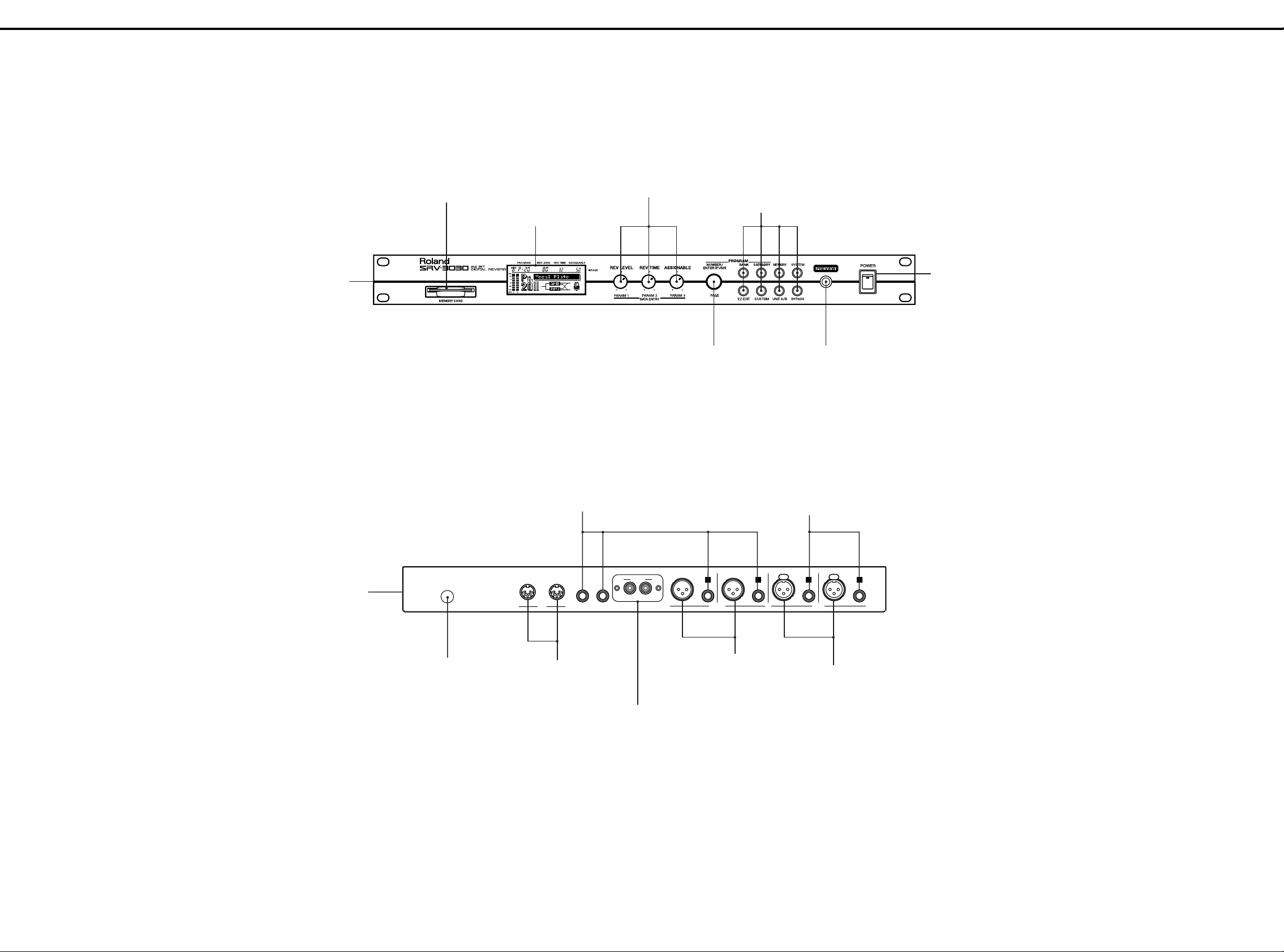
INPUT Jacks (A, B) : XLR-3-31, TRS
OUTPUT Jacks (A, B) : XLR-3-32, TRS
* XLR 1:GND, 2 :HOT, 3 :COLD
TRS T:HOT, R :COLD, S :GND
FOOT SW Jack
EXP PEDAL Jack
MIDI Connectors (IN, OUT/THRU)
SRV-3030D:
DIGITAL INPUT Jack : Coaxial
DIGITAL OUTPUT Jack : Coaxial
* S/P DIF, EIAJ CP-1201
• Power Supply
AC 117 V, AC 230 V, or AC 240 V
• Power Consumption
22 W
• Dimensions
SRV-3030 : 482 (W) x 204 (D) x 44 (H) mm
(EIA-1U rack mount type)
19 (W) x 8(D) x 1-3/4 (H) inches
SRV-3030D : 482 (W) x 205 (D) x 44 (H) mm
(EIA-1U rack mount type)
19 (W) x 8-1/14 (D) x 1-3/4 (H) inches
●接続端子
ジャック(A、B):
INPUT
OUTPUT
XLR
TRS標準 T:HOT、R:COLD、S:GND
FOOT SW
EXP PEDAL
MIDI
SRV-3030D
DIGITAL INPUT JACK
DIGITAL OUTPUT JACK:
S/P DIF、EIAJ CP-1201
●電源
AC100 V(50/60Hz
●消費電力
15 W
●外形寸法
SRV-3030: 482
SRV-3030D: 482
ジャック(A、B):
タイプ 1:
コネクター(IN、
GND、2:HOT、 3:COLD
ジャック
ジャック
:
)
(幅)×
mm(EIA-1U
(幅)×
mm(EIA-1U
XLR-3-31
XLR-3-32
OUT/THRU
:コアキシャル・タイプ
コアキシャル・タイプ
準拠
)
(奥行)×44(高さ)
204
ラック・マウント・タイプ)
(奥行)×44(高さ)
205
ラック・マウント・タイプ)
タイプ、
タイプ、
TRS
TRS
標準
標準
• Weight
2.8 kg/6 lbs 3 oz
• Accessories
Owner's Manual English (71236067)
MIDI Inplementation Jpanese (17048485)
MIDI Inplementation English (17048486)
Preset List (01908601)
Rack Mount Washer set (71346223)
• Options
Foot Switch : FS-5U, FS-5L
Expression Pedal : EV-5, FV-300L + PCS-33
Memory Card : S2M-5, S4M-5
* 0dBm = 0.775 Vrms
* In the interest of product improvement, the
specifications and/or appearance of this unit are
subject to change without prior notice.
●重量
2.8 kg
●付属品
取扱説明書
インプリメンテーション 和文
MIDI
インプリメンテーション 英文
MIDI
プリセット リスト
保証書
ラック・マウント用ワッシャーセット
●別売品
フット・スイッチ:
エクスプレッション・ペダル:
メモリー・カード:
0dBm = 0.775 Vrms
製品の仕様および外観は、改良のため予告なく変更する
ことがあります。
(71230389)
(40232334)
DP-2、FS-5U/5L(BOSS
EV-5、FV-300L+PCS-33
S2M-5、S4M-5
(17048485)
(17048486)
(01908601)
(71346223)
)
2
Page 3
May,1999 SRV-3030/3030D
LOCATION OF CONTROLS /パネル配置図
/パネル配置図
/パネル配置図/パネル配置図
FRONT PANEL
(01671212)
ESCUTCHEON
(01786712)
DISPLAY COVER
(01671245)
LCD UNIT RCM6043T-B
(01671312)
11M/M ROTARY POTENTIOMETER
RK11K112 10KB
(00783045)
M R-KNOB MF BLK
(22485188)
TACT SWITCH SKQNAD
(00894656)
F C-KEYTOP SX4H BLK
(01670501)
ROTARY ENCODER
EC11B1524209 L1=15
(00344578)
M R-KNOB 248-307 L BLK
(22485307)
TACT SWITCH SKQNAD
(00894656)
F C-KEYTOP SX1H BLK
(01670512)
POWER SWITCH AJ76200B
(01897412)
SWITCH COVER 721128-18
(12339355)
FRONT VIEW
BOTTOM CHASSIS
(01671223)
AC
THRU/ OUT
MIDI
AC CORD 100V
DP-360-J06 VFF2P
(13439801Y0)
MIDI CONNECTOR
2P YKF51-5048
(13429676)
AC CORD 117V
UP-882-J03
SJT2P 18AWG/105
(13439836D0)
AC CORD 230VE/230VEU
EP-474-E31 H03VVH2-F 2P
(13499176F0)
AC CORD 240VA SP-856-J12
ES-206-75HMA 2P
(13499208D0)
6.5MM JACK LGR4609-7100
(00569278)
EXP PEDAL
FOOT SW
IN
DIGITAL
OUT IN
XLR JACK NC3MAH
(00679767)
RCA PIN JACK (for SRV-3030D)
YKC21-3044 (PIN 0/0)
(00458801)
EXP PANEL (for SRV-3030D)
(01786734)
EXP COVER (for SRV-3030)
(01671301)
B
OUTPUT
6.5MM JACK YKB21-5006
(STEREO W/SW)
(13449252)
A
B A
INPUT
XLR JACK NC3FAH-1
(00679778)
:
GND
1
:
2
HOT
:
COLD3
REAR VIEW
3
Page 4
May,1999SRV-3030/3030D
0
1 2 3 4 5 6 7 8 9 10111213141516171819202122232425262728
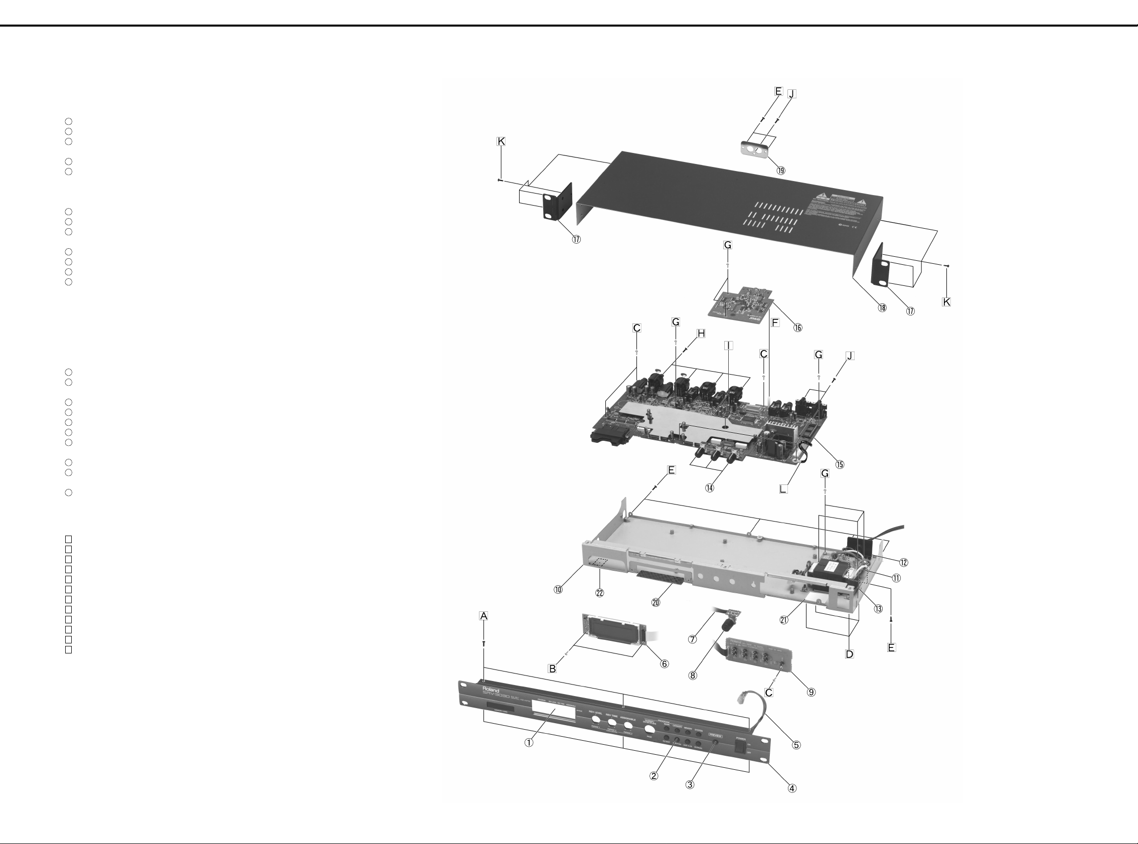
EXPLODED VIEW /分解図
EXPLODED VIEW /分解図
A
[PARTS]
No.PARTS No. PARTS NAME
1
B
C
D
E
F
G
H
I
J
K
L
01671245 DISPLAY COVER
2
01670501 F C-KEYTOP SX4H BLK
3
01670512 F C-KEYTOP SX1H BLK
40230812 NITTO DOUBLE SIDED ADHESIVE TAPE #541 10x10
4
01671212 FRONT PANEL
5
01897412 POWER SWITCH AJ76200B
12339355 SWITCH COVER 721128-18
01897890 WIRING1 2P L210 AWG20 (for POWER SWITCH)
40016512 INSYULOK TIE 80M/M T-18S
6
01671312 LCD UNIT RCM6043T-B
7
********
8
00344578 ROTARY ENCODER EC11B1524209 L1=15
22485307 M R-KNOB 248-307 L BLK
9
********
10
01671223 BOTTOM CHASSIS
11
********
12
13439801Y0 AC CORD 100V DP-360-J06 VFF2P
13439836D0 AC CORD 120V UP-882-J03 SJT2P 18AWG/105
13499176F0 AC CORD 220V EP-474-E31 H03VVH2-F 2P
13499208D0 AC CORD 240VA SP-856-J12 ES-206-75HMA 2P
12369533 CORD BUSHING KF-41
12369532 CORD BUSHING KR-61 (for 117V)
00456567 CORD HOLDER (for 100V/230VE/230EU/240VA)
00458767 CORD HOLDER (for 117V)
13
01780001 UNIVERSAL PWR TRANS
14
00783045 11M/M ROTARY POT. RK11K112 10KB
22485188 M R-KNOB MF BLK
15
71230478 MAIN BOARD ASSY
16
71236745 DIG. I/O BOARD ASSY (for SRV-3030D)
17
22123568 1U RACK MOUNT ANGLE
18
01671234 TOP COVER
19
01671301 EXP COVER (for SRV-3030)
01786734 EXP PANEL (for SRV-3030D)
2
40122612 NITTO ACETATE TAPE #5 BLACK W10MM 30M 20P
21
40233501 CAUTION LABEL (for 100V)
40017089 CAUTION SEAL CSA COVER (for 117V)
22
22350313 FOOT MKS 235-313
ENC BOARD ASSY
SWITCH BOARD ASSY
PS BOARD ASSY
(for 100V/230VE/230EU/240VA)
M
[SCREW]
No.PARTS No. PARTS NAME
A
N
O
P
Q
40015967 SCREW M3x6 FLAT TAPTITE S BZC
B
40239290 SCREW M2.6x8 W-SEMS WITH SMALL WASHER ZC
C
40012512 SCREW M3x6 BINDING TAPTITE S ZC
D
40011745 HEX NUT M4 W/SPRING WASHER FECM ZC
E
40342578 SCREW M3x6 BINDING TAPTITE S BZC
F
01786745 PWB SPACER MDLSP1-20M-01 (for SRV-3030D)
G
40013056 SCREW M3x6 PAN MACHINE W/SW+SMALL PW ZC
H
40233012 SCREW M2.6x8 BINDING TAPTITE FEBZC
I
01904912 BOSS NUT M3/20/5.5 (for SRV-3030D)
J
40011312 SCREW M3x8 BINDING TAPTITE P FE BZC
K
40011378 SCREW M4x8 BINDING TAPTITE S FE BZC
L
40017356 COATING CLIP CS-4
/分解図
/分解図/分解図
/分解図
/分解図/分解図
R
S
T
U
4
Page 5
May,1999 SRV-3030/3030D
1 2 3 4 5 6 7 8 9 10 11 12 13 14 15 16 17 18 19 20 21 22 23 24 25 26 27 28
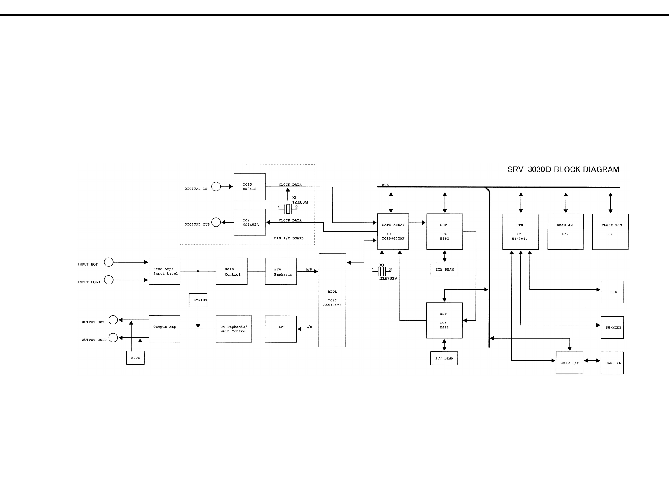
BLOCK DIAGRAM /ブロック図
A
/ブロック図
/ブロック図/ブロック図
B
C
D
E
F
G
H
I
J
K
L
M
N
O
P
Q
R
S
T
U
5
Page 6
May,1999SRV-3030/3030D
PARTS LIST /パーツリスト
SAFETY PRECAUTIONS:
The parts marked have
safety-related characteristics.
Use only listed parts for
replacement.
安全上の注意:
が付いている部品は、安全
上特別な規格でつくられたも
のです。
交換の際は、注意をよく読み、
指定された部品番号以外の部
品は使わないようにして下さ
い。
/パーツリスト
/パーツリスト/パーツリスト
SAFETY PRECAUTIONS:
The parts marked have safety-related characteristics. Use only listed parts for replacement.
Ex. 10 22575241 Sharp Key C-20/50
Failure to completely fill the above items with correct number and description will result in delayed or
even undelivered replacement.
パーツ発注に関するお願い
パーツ発注に関するお願い
パーツ発注に関するお願いパーツ発注に関するお願い
オーダーシートには、必ず下記の4項目は正確に記入して下さい。(例外は除く)
例
もし記入漏れ、誤記等が有る場合、必要部品が発送出来なかったり、大幅な遅れの原因になります。
ご協力をお願いします。
QTY PART NUMBER DESCRIPTION MODEL NUMBER
15 2247017300 Knob (orange) DAC-15D
必要数
) 10 22575241 Sharp Key C-20/50
15 2247017300 Knob (orange) DAC-15D
パーツナンバー 品 名 使用機種
NOTE: The parts marked # are new. (initial parts)
注意:#が付いた部品は新規部品です。
MAIN BOARD ASSY→MB SWITCH BOARD ASSY→SB ENC BOARD ASSY→EB
PS BOARD ASSY→PB DIG. I/O BOARD ASSY→DB
CASING / ケース
# 01671212 FRONT PANEL 1
# 016712 34 TOP COVER 1
# 01671223 BOTTOM CHASSIS 1
# 01671245 DISPLAY COVER 1
# 016713 01 EXP COVER for SRV-3030 1
# 01786734 EXP PANEL DIGITAL IN/OUT for SRV-3030D 1
# 01786712 ESCUTCHEON MEMORY CARD 1
KNOB, BUTTON / つまみ、ボタン
SWITCH / スイッチ
# 01897412 AJ76200B POWER SWITCH 1
# 00894656 SKQNAD TACT SWITCH 9
JACK, SOCKET / ジャック、ソケット
# 01780712 CN015P-3013-0 CARD CONECTR CN3 on MB 1
DISPLAY UNIT / 表示ユニット
PCB ASSY / 基板完成品
# 71230478 MAIN BOARD ASSY (EXG) 1
# 71236023 SW SHEET ASSY 1
#
#
#
# 712367 45 DIG. I/O BOARD ASSY for SRV-3030D 1
IC/ 集積回路
# 01670689 HD6433044S(VER.1.00) CPU IC1 on MB 1
# 01780256 TC190G02AF-0017(AMO) I/F CUSTOM IC12 on MB 1
# 01670701 MSM514260C-50JS-7DR1 DRAM IC3.IC5.IC7 on MB 3
# 016799 90 AK4524VF AD/DA COVERTER IC22 on MB 1
ケース
ケースケース
つまみ、ボタン
つまみ、ボタンつまみ、ボタン
!
12339355 SWITCH COVER 721128-18 1
22123568 1U RACK MOUNT ANGLE 2
22350313 FOOT MKS 235-313 4
01670501 F C-KEYTOP SX4H BLK PROGRAM 2
01670512 F C-KEYTOP SX1H BLK PREVIEW 1
22485188 M R-KNOB 248-188 MF BLK DATA ENTRY 3
22485307 M R-KNOB 248-307 L BLK ENCODER 1
スイッチ
スイッチスイッチ
!
ジャック、ソケット
ジャック、ソケットジャック、ソケット
00569278 LGR4609-7100 6.5MM JACK JK2.JK8.JK10.JK11 on MB 4
13449252 YKB21-5006 (STEREO W/SW) 6.5MM JACK JK4.JK6 on MB 2
00679767 NC3MAH XLR JACK JK7.JK9 on MB 2
00679778 NC3FAH-1 XLR JACK JK3.JK5 on MB 2
13429676 YKF51-5048 MIDI CONNECTOR JK1 on MB 1
00458801 YKC21-3044 (PIN 0/0) DIGITAL IN/OUT JK1 on DB 1
表示ユニット
表示ユニット表示ユニット
01671312 RCM6043T-B LCD UNIT 1
NOTE: Replacement LCD UNIT RCM6043T-B should be made on a unit base.
注意:
E
NOTE: 'SW SHEET ASSY' includes the following parts.
注意: 補修用
********
********
********
集積回路
集積回路集積回路
00892556 TC170C140AF-003 (ESP2) CUSTOM IC4.IC6 on MB 2
01341167 LH28F400SUT-NF60 FLASH MEMORY IC2 on MB 1
00675278 CS8402A-CP TRNSCEIVER IC2 on DB 1
00675290 CS8412-CP RECEIVER IC15 on DB 1
15269201H0 HD74LS04FPEL TTL IC9 on MB 1
15259126 TC4W66F CMOS IC33 on MB 1
15259104 HD14052BFPEL CMOS IC23.IC30 on MB 2
00127490 TC7W08F(TE12L) CMOS IC31 on MB 1
01786690 TC7SET08F(TE85L) CMOS IC40 on MB 1
15249121 TC7W04F(TE12L) CMOS IC17 on MB 1
15259885 TC7S32F(TE85L) CMOS IC39 on MB 1
15249104 TC7S04F(TE85L) CMOS IC37 on MB 1
15249112 TC7W32F(TE12L) CMOS IC36.IC38 on MB 2
00232645 TC7W14F(TE12L) CMOS IC10 on MB 1
LCD UNIT RCM6043T-B
基板完成品
基板完成品基板完成品
SW SHEET ASSY
ENC BOARD ASSY 1
SWITCH BOARD ASSY 1
PS BOARD ASSY 1
の交換は、ユニット単位で行って下さい。補修品は、ユニット単位。
は、下記の部品を含みます。
# 01670734 TC74VHC541F CMOS IC13.CI15 on MB 2
# 01670745 TC74VHCT541AF CMOS IC14 on MB 1
# 01670789 TC74VHCT08AF C M OS IC16 on MB 1
15189261 M5218AFP-600E BIPOLAR OP AMP IC11.IC25.IC26 on MB 3
15289105 UPC4570G2-E2 BIPOLAR OP AMP IC18.IC19.IC.20.IC24.IC34 on MB 5
# 0167 089 0 PQ3DZ53U REGULATOR IC32 on MB 1
15199256 TA78L005AP(TPE6) REGULATOR IC21 on MB 1
!
15199184 AN78M15F 0.5A/15V REGULATOR IC28 on MB 1
!
15199185 AN79M15F 0.5A/-15V REGULATOR IC29 on MB 1
15199293 L88R05D REGULATOR IC27 on MB 1
!
15289125 PC-410KT 178FAY PHOTO COUPLER IC8 on MB 1
15259702T0 TC74HC02AF(EL) NOR GATE IC11 on DB 1
# 1524 912 6T 0 TC74HC74 AF(E L ) D FLIP-FLOP IC8.IC10 on DB 2
15259704 TC74HC04AF(EL) HEX INVERTER IC4 on DB 1
15259708T0 TC74HC08AF(EL) AND GATE IC7 on DB 1
# 1525 979 9T 0 TC74HC367A F(E L) BUS BUFFER IC5.I C14 on D B 1
00893978 TC74VHC393F(EL) COUNTER IC13 on DB 1
TRANSISTOR / トランジスター
15309110 2SA1312-GR-TE85R(CHIP) TRANSISTOR Q26.Q28 on MB 2
15329105 2SK208Y-TE85L FET TRANSISTOR Q5.Q6.Q7.Q8.Q9.Q10.Q22.Q23.Q25.Q27.Q31.
15329521 RN1307-TE85R TRANSISTOR Q16.Q18.Q20.Q24.Q30.Q34 on MB 6
15329533 RN2307-TE85R TRANSISTOR Q15.Q17.Q19.Q21.Q29.Q33 on MB 6
00898201 RN2421-TE85L TRANSISTOR Q3.Q4 on MB 2
15329505 DTC314TK T146 DIGITAL TRANSISTOR Q11.Q12.Q13.Q14 on MB 4
DIODE / ダイオード
15019126 1SS133 T-77 SWITCHING DIODE on SB 9
15339119T0 1SS352(TPH3) SWITCHING DIODE D1.D3 on MB 2
# 01670667 D5SB20-4000 BRIDGE DIODE D11 on MB 1
01679867 S1VBA20 BRIDGE DIODE D12 on MB 1
15339120T0 1SS302-TE85R ARRAY D IODE D5.D10.D13 .D25.D26.D27 on MB 6
15339121 1SS301-TE85R(CHIP) DIODE D4.D6.D7.D8.D14 on MB 5
RESISTOR / 抵抗
# 01231734 ERDS2TY0T CARBON RESISTER L21.L3 on DB 2
15399926 MCR50-101J (CHIP) MTL.FILM RESISTOR R105.R107.R109.R111 on MB 4
15399927 MCR50-221J (CHIP) MTL.FILM RESISTOR R138.R139.R140.R141 on MB 4
00567156 RPC05T 102 J MTL.FILM RESISTOR 23
00567101 RPC05T 391 J MTL.FILM RESISTOR 2
00567256 RPC05T 562 J MTL.FILM RESISTOR 14
00567023 RPC05T 101 J MTL.FILM RESISTOR 14
00567456 RPC05T 224 J MTL.FILM RESISTOR 5
00567378 RPC05T 473 J MTL.FILM RESISTOR 8
00567190 RPC05T 222 J MTL.FILM RESISTOR 7
00567289 RPC05T 103 J MTL.FILM RESISTOR 52
00566967 RPC05T 470 J MTL.FILM RESISTOR 8
00566989 RPC05T 560 J MTL.FILM RESISTOR 2
00567034 RPC05T 121 J MTL.FILM RESISTOR 1
00567067 RPC05T 221 J MTL.FILM RESISTOR 2
00567112 RPC05T 471 J MTL.FILM RESISTOR 2
00567178 RPC05T 152 J MTL.FILM RESISTOR 1
00567212 RPC05T 332 J MTL.FILM RESISTOR 3
00567345 RPC05T 333 J MTL.FILM RESISTOR 3
00567412 RPC05T 104 J MTL.FILM RESISTOR 9
00567434 RPC05T 154 J MTL.FILM RESISTOR 2
00567556 RPC05T 105 J MTL.FILM RESISTOR 6
00567001 RPC05T 750 J MTL.FILM RESISTOR 1
15399349 RPC10T 100 J 1/10W MTL.FILM RESISTOR 1
00126112 EXBV8V101JV RESISTOR ARRAY RA3.RA4.RA5.RA14.RA15 on MB 5
15399965 RCE9A103JAG7A (10KOHM x8) RESISTOR ARRAY RA1.RA2.RA6.RA10.RA11.RA12.RA16 on MB 7
POTENTIOMETER / ボリューム
00783045 RK11K112 10KB 11M/M ROTARY POTENTIOMETER VR1.VR2.VR3 on MB 3
CAPACITOR / コンデンサー
!
01453278 DE1307E 472M-KH CERAMIC CAPACITOR C114 on PB 1
01674556 ECJ1VB1H472K CERAMIC CAPACITOR C76.C79.C99.C101 on MB 4
01675167 GRM39CH100D50PT CERAMIC CAPACITOR 16
00567978 GRM39F104Z25PT CERAMIC CAPACITOR 90
01235278 GRM39B473K16PT CERAMIC CAPACITOR 3
00566812 GRM39SL331J50PT CERAMIC CAPACITOR 4
00566856 GRM39SL681J50PT CERAMIC CAPACITOR 2
01675278 GRM39CH101J50PT CERAMIC CAPACITOR 1
01675234 GRM39CH470J50PT CERAMIC CAPACITOR 2
00567945 GRM39B103K50PT CERAMIC CAPACITOR 2
00567812 GRM39B821K50PT CERAMIC CAPACITOR 2
01672412 GRM39CH150D50PT CERAMIC CAPACITOR 2
!
01340112 16SC1M+T (OS) CHEMICAL CAPACITOR C122 1
15369104S0 6.3CV47BS CHEMICAL CAPACITOR C2.C4.C7 on DB 3
!
# 01896512 ECA1VHG102 CHEMICAL CAPACITOR C124.C125 2
00783778 ECEA2A470B CHEMICAL CAPACITOR C64.C66.C69.C71 4
!
01121078 ECEA1CM332 CHEMICAL CAPACITOR C119 1
15369109 ECEV0JA101SP CHEMICAL CAPACITOR C30.C31.C32 on DB 3
!
13639550 ECEA1CU101B 100UF/16V CHEM ICAL CAPACITOR C123.C130 2
13649269 ECA1CM100B 10UF/16V CHEMICAL CAPACITOR C5.C20.C46.C54.C57.C58.C59.C60.C61.C62.
13639549 ECA1CM470B CHEMICAL CAPACITOR C78.C81.C106.C107.C108.C109.C158.C159 8
00459778 ECST0JC476R 47UF/6.3V TANTALUM CAPACITOR C84.C86.C96.C97 on MB 4
00347223 ECST0JY106R (CHIP) TANTALUM CAPACITOR C92.C95.C146 3
# 01897401 TCFGB1C106M8R TANTALUM CAPACITOR C157.C160 2
INDUCTOR, COIL, FILTER / インダクター、コイル、 フィル ター
00565589 ACB2012M-600-T (CHIP) FERRITE BEAD L7.L8.L9.L10.L11.L12.L13.L14 8
12449268 BL02RN2-R62T2 FERRITE BEAD L1 on DB 1
12399506 BL03RN2-R62T2 FERRITE BEAD L1.L2.L3.L4.L5.L6.L15 7
12449452 BLM41A800SPT FERRITE BEAD L1.L20.L21 on MB 3
12449615 PT-10244-615 PULS TRANS FL1 onDB 1
トランジスター
トランジスタートランジスター
ダイオード
ダイオードダイオード
抵抗
抵抗抵抗
コンデンサー
コンデンサーコンデンサー
ボリューム
ボリュームボリューム
インダクター、コイル、フィルター
インダクター、コイル、フィルターインダクター、コイル、フィルター
Q32 on MB 12
C131 11
6
Page 7

May,1999 SRV-3030/3030D
The SRV-3030/3030D is provided with two software programs.
One is contained in the mask CPU and the other in flash ROM.
To identify the version of these software programs, press and
hold CATEGORY, UNIT A/B and SYSTEM buttons while turning
on POWER switch.
The LCD will display FLASH VER. at the upper left-hand of the
screen and CPU VER. at the upper center.
SRV-3030/3030D
にはマスク
CPU
内ソフトとフラッシュ
ROM
内ソフトの2種類が存在します。
それぞれのソフトのバージョンを確認するには、
[CATEGORY]
+ [UNITA/B] + [SYSTEM]
ボタンを押しながら、電源ONを行
なって下さい。
LCD
画面の上部に
左側:
FLASH VER.
中央:
CPU VER.
が表示されます。
♦
To save data through MIDI
Connect MIDI OUT of SRV-3030/3030D to MIDI IN of a
sequencer through a MIDI cable. Put the sequencer into the
record ready status and then turn on POWER switch on the
SRV-3030/3030D.
1. Press SYSTEM button.
2. Turn NUMBER/ENTER PUSH/PAGE knob (for simplicity,
call this “NUMBER/” knob) to display the BULK DUMP
screen.
3. Select the settings to be sent out by turning PARAM 1
knob.
Display Settings to be sent
ALL All setti ngs (standard selection)
SYSTEM All settings except programs
TEMP PROGRAM The programs currently invoked
1-100 All user programs(1-100)
4. Start recording on the sequencer.
5. Press NUMBER/ knob to start transmission.
The screen exits to the previous screen upon completion
of transmission.
6. Stop recording on the sequencer.
7. Press SYSTEM button to exit to the play mode.
♦
To load data through MIDI
Connect MIDI IN of SRV-3030/3030D to MIDI OUT of the
sequencer through the MIDI cable. From the SYSTEM_MIDI
CH screen, set the SRV-3030/3030D device ID to the one
used during recording on the sequencer.
1. Press SYSTEM button.
2. Turn NUMBER/ knob to display the BULK LOAD screen.
3. Press NUMBER/ knob to start loading.
4. Play the sequencer.
5. Upon completion of data play, stop the sequencer.
6. Press NUMBER/ knob to stop uploading.
7. Press SYSTEM button to exit to the play mode.
◆データのセーブ方法(
◆データのセーブ方法(◆データのセーブ方法(
◆データのセーブ方法(
MIDI
による)
による)による)
による)
シーケンサの
MIDI IN と SRV-3030/3030Dの MIDI OUT
を
接続し、シーケンサを録音待機状態にしてから、
SRV-3030/
3030D
の電源を入れて下さい。
1.
[SYSTEM]
ボタンを押す。
2.
[NUMBER ([PAGE])]
ツマミを回して、
BULK DUMP
画
面を表示させます。
3.
[PARAM1]
ツマミを回して、送信する設定を選びます。
(表示) (送信する設定)
ALL
すべての設定
*通常はこれを選択します。
SYSTEM
プログラム以外のすべての設定
TEMP PROGRAM
現在呼び出されているプログラム
1〜100
全ユーザー・プログラム(1〜
100
)
4.送信先がシーケンサの場合は、録音状態にします。
5.
[ENTER (PUSH)]
ボタンを押しますと、送信を開始しま
す。
送信が終了すると、送信前の画面に戻ります。
6.送信先のシーケンサを停止状態にします。
7.
[SYSTEM]
ボタンを押します。
プレイモードに戻ります。
◆データのロード方法(
◆データのロード方法(◆データのロード方法(
◆データのロード方法(
MIDI
による)
による)による)
による)
シーケンサの
MIDI OUTとSRV-3030/3030DのMIDI IN
を
接続し、
SRV-3030/3030D
のデバイス
ID(SYSTEM_ MIDI
CH
画面で設定できます。)をシーケンサに記録したときと
同じ設定にします。
1.
[SYSTEM]
ボタンを押します。
2.
[NUMBER ([PAGE])]
ツマミを回して、
"BULK LOAD"
画
面を表示させます。
3.
[ENTER (PUSH)]
ボタンを押し、
"LOAD"
を開始しま
す。
4.シーケンサを
"PLAY"
状態にします。
5.データ再生が終了しましたら、シーケンサを
"STOP"
状
態にします。
6.
[ENTER (PUSH)]
ボタンを押し、
"LOAD"
を終了しま
す。
7.
[SYSTEM]
ボタンを押し、プレイ・モードに戻ります。
1. Press MEMORY button.
2. Display “FACTORY RESET” screen by turning NUMBER/
knob.
3. Select TARGET “ALL” by turning PARAM 3 knob.
4. Press NUMBER/ button. The LCD will display “SURE?”.
5. Press NUMBER/ button to start the factory resetting.
Upon completion of the factory resetting, the unit will return
back to the play mode.
1.
[MEMORY]
ボタンを押します。
2.
[NUMBER ([PAGE])]
ツマミを回し、
LCD
画面表示を
"FACTRY RESET"
にします。
3.
[PARAM3]
ツマミを回し、
TARGET を"ALL"
にします。
4.
[ENTER (PUSH)]
ボタンを押しますと、
LCD
画面に
"SURE?"
と表示されます。
5.
[ENTER (PUSH)]
ボタンを押します。
ファクトリ−・リセットが実行され、プレイ・モードに
戻ります。
CRYSTAL, RESONATOR / クリスタル、発振器
00894034 MA-406 16.000MHZ TE24 CRYSTAL X1 on MB 1
00902301 MA-406 22.5792MHZ TE24 CRYSTAL X3 on MB 1
# 00124378 CA-301 12.288MHZ CRYSTAL X1 on DB
01453167 SG-8002DC 67.7376MHZ PHC OSCILLATOR X2 on MB 1
ENCODER / エンコーダー
CONNECTOR / コネクター
# 01786778 10-5061-030-004-856 CONNECTOR CN1 on DB
!
WIRING, CABLE / ワイヤリング、ケーブル
# 01897890 WIRING1 (2P L210 AWG20) for POWER SWITCH 1
# 403431 34 WIRING 6.5MM(1P) on MB 1
TRANSFORMER / トランス
!
AC CORD (INSTALLED) / 電気コード(据え付け式)
!
!
!
!
!
SCREW / ねじ類
PACKING / 梱包材
# 01671267 PACKING CASE 1
# 01891290 PAD for PACKING CASE 2
MISCELLANEOUS / その他
!
!
# 01897390 SHIELD COVER on MB 1
ACCESSORIES (STANDARD) / 標準付属品
# 71230389 OWNER'S MANUAL JAPANESE 1
# 71236067 OWNER'S MANUAL ENGLISH 1
# 17048485 MIDI INPLEMENTATION JAPANESE 1
# 17048486 MIDI INPLEMENTATION ENGLISH 1
# 01908601 PRESET LIST 1
# 71346223 RACK MOUNT WASHER SET 1
エンコーダー
エンコーダーエンコーダー
00344578 EC11B1524209 L1=15 ROTALY ENCODER 1
コネクター
コネクターコネクター
13429294 51048-0500(5P) CABLE HOLDER on EB 1
13429295 51048-0600(6P) CABLE HOLDER on SW 1
01890201 20-5061-030-058-856 CONNECTOR CN14 on MB 1
13369981 B5P-VH 7A/250V CONNECTOR CN6 1
13369601 52147-0610(6P) WIRE TRAP CN1 1
13369600 52147-0510(5P) WIRE TRAP CN16 1
13369793 52030-1610 FFC/FPC CONNECTOR CN2 1
01014656 RIBBON CABLE 5X150-P2.0 on EB 1
01782134 RIBBON CABLE 6X150-P2.0 on SW 1
01780001 UNIVERSAL PWR TRANS 1
13439801Y0 DP-360-J06 VFF2P AC CORD 100V 1
13439836D0 UP-882-J03 SJT2P 18AWG/105 AC CORD 117V 1
13499176F0 EP-474-E31 H03VVH2-F 2P AC CORD 230VE/230VEU 1
13499208D0 SP-856-J12 ES- 206 -7 5H M A 2P AC CORD 240VA 1
00905234 ECP01-5A (PLUG FOR BRC-230T) EURO CONVERTER PLUG for 240VE 1
ねじ類
ねじ類ねじ類
40233012 SCREW M2.6x8 BINDING TAPTITE FEBZC 8
40239290 SCREW M2.6x8 W-SEMS WITH SMALL WASHER ZC 2
40342578 SCREW M3x6 BINDING TAPTITE S BZC 10
40012512 SCREW M3x6 BINDING TAPTITE S ZC 4
40015967 SCREW M3x6 FLAT TAPTITE S BZC 6
40013056 SCREW M3x6 PAN MACHINE W/SW+SMALL PW ZC 10
40011312 SCREW M3x8 BINDING TAPTITE P FE BZC 4
40013067 SCREW M3x8 PAN MACHINE W/SW+SMALL PW ZC 2
40011378 SCREW M4x8 BINDING TAPTITE S FE BZC 8
40011745 HEX NUT M4 W/SPRING WASHER FECM ZC 4
01904912 BOSS NUT M3/20/5.5 for SRV-3030D 2
梱包材
梱包材梱包材
40233501 CAUTION LABEL for 100V 1
40017089 CAUTION SEAL CSA COVER for 117V 1
12369533 CORD BUSHING KF-41 for 100V/230VE/230EU/240VA 1
12369532 CORD BUSHING KR-61 for 117V 1
00456567 CORD HOLDER for 100V/230VE/230EU/240VA 1
00458767 CORD HOLDER for 117V 1
01786745 PWB SPACER MDLSP1-20M-01 for SRV-3 030D 1
00345489 TRMINAL V.LUG P-92 187 CN17.CN18 on PB 2
40016378 TRMINAL TER61-0171 CN8.CN9.CN10.CN11.CN20 on PB 5
12469212 HEATSINK PC1115-30-PB (P=19) HT2 on MB 1
00893867 HEATSINK HT1 on MB 1
40016512 INSYULOK TIE 80M/M T-18S 2
40017356 COATING CLIP CS-4 on MB 1
40122612 NITTO ACETATE TAPE #5 BLACK W10MM 30M 20P for BOTTOM CHASSIS
40230812 NITTO DOUBLE SIDED ADHESIVE TAPE #541 10X10 for KEYTOP
40232334
クリスタル、発振器
クリスタル、発振器クリスタル、発振器
ワイヤリング、ケーブル
ワイヤリング、ケーブルワイヤリング、ケーブル
トランス
トランストランス
電気コード(据え付け式)
電気コード(据え付け式)電気コード(据え付け式)
その他
その他その他
標準付属品
標準付属品標準付属品
保証書
(JAPAN ONLY) 1
VERIFYING VERSION NUMBERS /バージョンナンバーの確認方法
SAVING/LOADING DATA /データのセーブとロード
FACTORY RESETTING /ファクトリー・リセットの方法
/データのセーブとロード
/データのセーブとロード/データのセーブとロード
/ファクトリー・リセットの方法
/ファクトリー・リセットの方法/ファクトリー・リセットの方法
/バージョンナンバーの確認方法
/バージョンナンバーの確認方法/バージョンナンバーの確認方法
7
Page 8

SYSTEM SOFTWARE UPDATE USING THE SMF ////
、
11: Analog characteristics test
12: D I/O test (SRV-3030D only)
13: Factory preset - factory test
11: アナログ特性テスト
12:
D I/O
テスト:
SRV-3030D
のみ
13: ファクトリ・プリセット:工場でのみ使用
•
To start test sequence
Press NUMBER/ knob.
1: Sequential test - factory test (skip this option)
2: LCD test
All dots increase and then decrease contrast twice.
Visually check for contrast and missing dots.
3: Switch test
Operate the following controls and check the results
indicated on the LCD. The next test can be started when
the current control passes the test.
PARAM 1: Check to see that the reading changes for
0 to 100 to 0.
PARAM 2: Check to see that the reading changes for
0 to 100 to 0.
PARAM 3: Check to see that the reading changes for
0 to 100 to 0.
NUMBER/: Gradually turn the knob clockwise until three clicks
are felt and then counterclockwise for three clicks.
Verify the resulting changes.
While observing the LCD screen, turn on and off the
following switches one by one in the order given.
[ENTER] → [BANK] → [CATEGORY] → [MEMORY] →
[SYSTEM] → [PREVIEW] → [BYPASS] → [UNIT A/B] →
[CUSTOM] → [EZ EDIT]
Depress and release the foot switch.
When all switches have passed the test, the test 4 will
automatically start. As the name implies, a self-test
requires only selecting and starting signal from NUMBER/
knob (simply press the knob).
4: DRAM test (self-test)
5: Flash test (self-test)
6: MIDI test (self-test)
7: Card test (self-test) - factory test (skip this option)
8: DSP test (self-test)
9: GA test (self-test)
10: I/O test (self-test)
11: Analog characteristics test
•
Residual noise
With the unit in THRU mode.
Using the noise meter, measure the noise level at
balanced OUTPUT A (connect across HOT and GND, and
COLD and GND). The readings must be -80 dBm or
below. Repeat the measurement for balanced OUTPUT B.
The difference between OUTPUT A and B in readings
must be 2 dBm or below.
•
Total distortion factor (distortion factor)
With the unit in THRU mode.
Connect a 600( shunt resistor to balanced INPUT A.
Set the distortion meter: output = sine wave, 1 kHz, +4
dBm, HPF = 400 Hz, LPF = 30 kHz.
Measure distortion through balanced INPUT A to
OUTPUT A (HOT and GND and COLD and GND). Verify
0.02% or less distortion factor.
Repeat measurements for INPUT B to OUTPUT B.
・各テスト項目選択方法
・各テスト項目選択方法・各テスト項目選択方法
・各テスト項目選択方法
[ENTER (PUSH)]
ボタンでスタートします。
1:シーケンシャル・テスト(工場でのみ行います。)
2:
LCD
テスト
全ドットが段々に明暗(2回)します。
コントラスト、ドットの欠けを目視で確認します。
3:SWテスト
以下の操作を順次行います。
それぞれ
"OK"
であれば順次テストが進みます。
PARAM 1 :0→100→0
まで、変化することを確認し
ます。
PARAM 2
:同上
PARAM 3
:同上
EXP.PEDAL
:同上
NUMBER (PAGE)
:右にゆっくり3クリック以上、左に
ゆっくり3クリック以上、変化を確認
します。
下記順に各
SW
を押して離します。
各項目に対応した内容が、
LCD
画面に表示されます。)
[ENTER] → [BANK] → [CATEGORY] → [MEMORY]
→
[SYSTEM] → [PREVIEW] → [BYPASS] → [UNIT A/
B] → [CUSTOM] → [EZ EDIT]
FOOT SWITCH
踏んで離します。
以下の(セルフテスト)は、項目ごとに自動的にテスト
されます。
別の項目に進む場合は、
[ENTER (PUSH)]
ボタンを押しま
す。
4: DRAM
テスト(セルフテスト)
5: FLASH
テスト(セルフテスト)
6: MIDI
テスト(セルフテスト)
7: CARD
テスト(工場でのみ行います。)
8:DSP
テスト(セルフテスト)
9: GA
テスト(セルフテスト)
10:
I/O
テスト(セルフテスト)
11:アナログ特性テスト
・残留ノイズの測定
スルー状態にて、
OUTPUT A , B (
バランス接続)の残
留ノイズをノイズメーターで測定し、
"-80dBm"
以下で
あることを確認して下さい。
また
A , B
の値の差を
"2dBm"
以内とします。
HOT-GND , COLD-GND
間の値を個々に測定。)
・歪率(全歪率)の測定
スルー状態にて、
INPUT A - OUTPUT A
(バランス接
続)
, INPUT B-OUTPUT B
(バランス接続)間の歪率
を歪率計にて測定し、
"0.02%"
以下であることを確認
して下さい。
(
HOT - GND , COLD - GND
間の値を個々に測定し、
入力側は
"600Ω"
でシャント状態にて測定します。)
*歪率計のセッティング:出力信号 正弦波
1kHz
+4dBm , HPF 400Hz LPF 30kHz ON
SMF によるシステムソフトウェアのアップデートについて
♦
♦
♦
TEST MODE /テストモード
♦
♦
8
によるシステムソフトウェアのアップデートについて
によるシステムソフトウェアのアップデートについてによるシステムソフトウェアのアップデートについて
Updating the system software using SMF
The system software of SRV-3030/3030D can be updated
by using the latest version of standard MIDI file.
The update disc (P/No.17048598) contains the following
SMF data:
SRV030-1.MID
SRV030-2.MID
SRV030-3.MID
SRV030-4.MID
Updating procedure
Through MIDI
1. Connect MIDI IN of SRV-3030/3030D to MIDI OUT of the
sequencer through the MIDI cable.
2. While holding down CATEGORY, UNIT A/B and
SYSTEM buttons, turn on POWER switch.
3. Turn NUMBER/ knob to display "UPDATE from MIDI" on
the screen.
4. Press NUMBER/ knob to start loading.
5. Play the sequencer.
6. Upon completion of play, set the sequencer to stop
mode.
Updating by using the upgrading memory card
(P/No.17048599)
1. Insert an upgrading memory card (smart media) into
MEMORY CARD slot.
2. While holding down CATEGORY, UNIT A/B and
SYSTEM buttons, turn on POWER switch.
3. The LCD will display "UPDATE from CARD". Press
NUMBER/ knob to start updating.
/テストモード
Before entering test mode
•
Tools required
Oscilloscope, noise meter, distortion meter, amps,
speakers, smart media (S2M-5, S4M-5), stereo connection
cables, mono connection cables, MIDI-capable equipment,
MIDI cable, expression pedal (EV-5 or equivalent), foot
switch (DP-2, FS-5U, etc.)
EV-5: set MIN knob to "0".
FS-5U: set the polarity switch to the position close to the
jack.
Using connection cables with standard plug, connect INPUT
A to OUTPUT A and INPUT B to OUTPUT B.
Using connection cables with MIDI CONNECTOR, connect
MIDI IN to MIDI OUT.
/テストモード/テストモード
ENTERING TEST MODE (B) (B: USER TEST MODE)
While holding CUSTOM, MEMORY and BYPASS buttons,
turn on POWER switch.
Select the test option by turning NUMBER/ knob. Follow the
instruction given in the selected page.
If the unit fails a test, turn off the unit, take corrective action
and then restart the test.
Pages
1: Sequential test - factory test
2: LCD test
3: Switch test
4: DRAM test (self-test)
5: F lash tes t (self-test)
6: MIDI test (se l f-test)
7: Card test (self-test) - factory test
8: DSP test (self-test)
9: GA test (self-test)
10: I/O test (self-test)
SMF
◆◆◆◆
◆◆◆◆
◆メモリーカード
◆メモリーカード
◆メモリーカード◆メモリーカード
◆テストモードに入る前の準備
◆テストモードに入る前の準備
◆テストモードに入る前の準備◆テストモードに入る前の準備
◆テストモード(B)の入り方
◆テストモード(B)の入り方
◆テストモード(B)の入り方◆テストモード(B)の入り方
によるシステムソフトウェアのアップデート
によるシステムソフトウェアのアップデート
によるシステムソフトウェアのアップデートによるシステムソフトウェアのアップデート
SRV-3030/3030D
される最新のシステムを使ってシステムソフトウェアの
アップデートが可能です。
アップデートディスク(
な
データが保存されています。
SMF
SRV030-1.MID
SRV030-2.MID
SRV030-3.MID
SRV030-4.MID
次の手順でシステムソフトウェアのアップデートを行って
ください。
MIDI
による方法
による方法
による方法による方法
1.シーケンサの
を接続します。
IN
2.
[CATEGORY]+[UNIT A/B]+[SYSTEM]
ら、電源を入れます。
3.
[NUMBER ([PAGE])]
"UPDATE from MID I"
4.
[ENTER (PUSH)]
す。
5.シーケンサを
6.データ再生が終了しましたら、シーケンサを
態にします。
1.バージョンアップ用のメモリーカード(スマートメディ
ア)を差し込みます。
2.
[CATEGORY]+[UNIT A/B]+[SYSTEM]
ら、電源を入れます。
3.
・使用機材
・使用機材
・使用機材・使用機材
[CUSTOM]+[MEMORY]+[BYPASS]
源を入れます。
各項目のテストを
し、各ページの指示に従ってください。
10:
画面表示が
LCD
で、
[ENTER (PUSH)]
が実行されます。
オシロスコープ、ノイズメーター、歪率計、アンプ、ス
ピーカー、
MIDI 機器
& MONO
EXP PEDALはEV-5 , FOOT SWITCHはDP-2, FS-5U
使用可能ですが、以下の様な設定が必要です。
・
の横側の
EV-5
い。
・
FS-5U
(ジャック側)に設定してください。
また、
INPUT B - OUTPUT B
続しておいて下さい。
また,
ブルにて接続しておいてください。
それぞれのテスト項目が
ますが、
終了してください。
ページ構成
1: シーケンシャル・テスト(選択):工場でのみ使用
2:
LCD
3:SWテスト
4:
DRAM
5:
FLASH
6:
MIDI
7:
CARD
8:
DSP
9:GAテスト(セルフテスト)
I/O
接続ケーブル
を使用する場合:
I/O
MIDI
テスト(セルフテスト)
は、スタンダード
P/No.17048598
MIDI OUT と SRV-3030/3030D の MIDI
ツマミを回して、
にします。
ボタンを押して、
"PLAY"
状態にします。
(P/No.17048599)
"UPDARE from CARD"
ボタンを押すとバージョンアップ
EXP PEDAL 、 FOOT SWITCH、MIDI CABLE
スマートメディア(
設定つまみを
MIN
テストのために、
テストのために,
[NUMBER ([PAGE])]
の場合は、電源を切ってテストモードを
"NG"
テスト
テスト(セルフテスト)
テスト(セルフテスト)
テスト(セルフテスト)
テスト(セルフテスト)
テスト(セルフテスト:工場でのみ使用
S2M-5,S4M-5 )、 STEREO
POLARITY SWITCHを"
INPUT A - OUTPUT A,
を標準
JACK
MIDI IN-OUTをMIDI
であれば順次テストが進み
"OK"
ファイルで供給
MIDI
)には、次のよう
ボタンを押しなが
画面表示を
LCD
"LOAD"
による方法
による方法
による方法による方法
"0"
ボタンを押しながら、電
ツマミを回して選択
状態にしま
"STOP"
ボタンを押しなが
になりますの
に設定してくださ
右側
ケーブルにて、接
May,1999SRV-3030/3030D
状
が
"
ケー
Page 9

May,1999 SRV-3030/3030D
•
CARD TEST
•
Formatting smart media
1. Insert a smart media into MEMORY CARD slot.
2. Press MEMORY button.
3. Turn NUMBER/ knob to select "CARD FORMAT".
4. Press NUBER/ knob. The screen displays the
acknowledge message.
5. Press NUBER/ knob. The formatting process starts.
・・・・
CARD
テスト
テストテスト
テスト
・・・・ スマートメディアのフォーマット
1.スマートメディアをメモリーカードスロットに差し込
みます。
2.
[MEMORY]
ボタンを押します。
3.
[NUMBER ([PAGE])]
ツマミを回して
"CARD
FORMAT"
を選択します。
4.
[ENTER (PUSH)]
ボタンを押しますと、確認のメッ
セージが
LCD
画面に表示されます。
5.
[ENTER (PUSH)]
ボタンを押しますと、フォーマット
が実行されます。
•
Testing smart media
1. Insert a formatted smart media into MEMORY CARD slot.
2. Press MEMORY button.
3. Turn PARAM 2 knob to select the destination bank (select
CARD-A) where the data is to be stored.
4. Turn PARAM 3 knob to select the destination program
number (select 01) where the data is to be stored.
5. Press NUMBER/ knob.
6. The LCD will display "SURE?". Press NUMBER/ knob.
7. Data have been written onto the card.
8. Press BANK button to select the bank on the card. Select
the program number assigned in step 4 above by turning
NUMBER/ knob.
9. Verify that the patch written in steps 4-7 remains saved.
•
Smart media voltage version automatic recognition (+3 V,
+5 V)
Insert a +5 V card, and then if available, +3 V card. Verify
that the unit correctly switches according to the voltage
version of the card.
••••
MIDI THRU TEST
•
Check the status of MIDI IN / OUT function.
1. Feed MIDI signal to MIDI IN.
2. Turn on the SRV-3030/3030D. ( Set it to MIDI THRU
mode. )
3. The data which input into MIDI IN and output the date
from MIDI OUT.
4. Confirm the data which output from MIDI OUT is as same
as the input data.
・スマートメディアのテスト
1.フォーマット済みのスマートメディアをメモリーカー
ドスロットに差し込みます。
2.
[MEMORY]
ボタンを押します。
3.
[PARAM2]
ツマミを回して、保存先のバンクを選びま
す。
(この場合、
CARD-A
を選択します。)
4.
[PARAM3]
ボタンを回して、保存先のプログラム・ナ
ンバーを選びます。(この場合、
01
を選択します。)
5.
[ENTER (PUSH)]
ボタンを押します。
6.
"SURE?" が LCD
画面表示されますので、
[ENTER
(PUSH)]
ボタンを押します。
7.カードへの書き込みが完了します。
8.書き込み内容のチェックをします。
[BANK]
ボタンを押して、カードのバンクを選択し、
[NUMBER ([PAGE])]
ツマミを回して、4.で行ったプ
ログラム・ナンバーを選択します。
9.4.〜7.で行った、パッチの内容が保存されている
ことが確認できれば
"OK"
です。
・スマートメディア(
+3V , +5V
用)自動判別テスト
スマートメディアカードの
+3V 用と +5V
用のカードがあ
れば、それぞれにて
CARD
テストを行ないます。
問題無く
CARD
テストが終了すれば、
"OK"
です。
・・・・
MIDI
スルー
スルースルー
スルー テスト
テストテスト
テスト
・
MIDI THRU
が正しく行われるかをチェックします。
1.キーボードなどの
MIDI
機器の
MIDI OUT と SRV-
3030/3030D のMIDI IN
を接続します。
次に、
SRV-3030/3030D の MIDI OUT
と音源などの
MIDI
機器の
MIDI IN
を接続します。
2.
SRV-3030/3030D 電源 ON
の状態(
MIDI THRU
状態)
にします。
3.1.で接続したキーボードを演 奏して、1.で接続し
た音源が正しく
MIDI DATA
を受信している事を音など
で確認します。
4.3.で
MIDI DATA
が正しく受信できていれば、
MIDI
THRU
は正常です。
•
Frequency response, bypass, muting
Input a 500 Hz, −20 dBm (155 mVpp), rectangular wave
to unbalance INPUT A and monitor the signal at
unbalance OUTPUT A on the oscilloscope. Check the
characteristics against the figures below. Repeat for
INPUT B and OUTPUT B.
Frequency response: THRU - Fig. 1
Mute : MUTE ON - Fig. 2
Bypass : BYPASS ON - Fig. 3
50mV, 500uS
・周波数特性・バイパス・ミュートの検査
個々の
INPUT から 500Hz , −20dBm( 155mVp-p
の矩形波を入力し、個々の
ロスコープにて確認します。
INPUT A - OUTPUT A
B - OUTPUT B
性バイパスミュートの動作を確認します。
下記の様な波形が観測されれば、問題無しとします。
f 特性
ミュート :ミュート状態にて(
バイパス :バイパス状態にて(
(アンバランス接続)間にて、
:スルー 状態にて (
Vpp=75mV
OUTPUT
(アンバランス接続)
への出力をオシ
)
Fig. 1
)
Fig. 2
)
Fig. 3
, INPUT
f
)
特
Fig. 1 THRE
12: D I/O test (SRV-3030D only)
•
Internal CLK
Hook up DIGITAL IN and OUT.
Connect OUTPUT A and OUT to separate amplifiers and
speakers.
ress NUMBER/ knob to display "1. INT 44" on the LCD
screen.
Monitor sine wave signals through the speakers.
Press NUMBER/ knob to display "2. INT 48" on the LCD
screen.
Monitor sine wave signals through the speakers.
•
External CLK
Connect DIGITAL IN of the SRV-3030D to a CD player
or DAT, and DIGITAL OUT to a D/A converter, e.g. DA-
400.
Connect OUTPUT A and B of the SRV-3030D and
ANALOG OUT of D/A converter to separate amplifiers
and speakers.
Press NUMBER/ knob to display "3. EXT" on the LCD
screen.
Verify that sine wave sounds from the D/A converter are
heard through speakers.
•
Error/recovery
Disconnect the plug from DIGITAL IN of SRV-3030D and
verify no sound is heard through the speakers.
Insert the plug into DIGITL IN and verify that all speakers
output sounds.
•
Emphasis check
Press NUMBER/ knob to display "3. EXT" on the LCD
screen.
Connect DIGITAL IN of the SRV-3030D to a device
capable of supplying emphasis on/off information. Verify
that "EM:xxx" is displayed on the LCD.
13: Factory preset - factory test (skip this option)
♦
Other checks
Preview
・・・・
In the normal operation mode, press PREVIEW button and
verify the preview tone.
Fig. 2 MUTE
12:
13:ファクトリー・リセット(工場でのみ行います。)
◆その他のチェック項目
◆その他のチェック項目
◆その他のチェック項目◆その他のチェック項目
・・・・ プレビューチェック
通常動作状態にて、
正しく鳴っているか、確認してください。
テスト(
D I/O
・インターナル
SRV-3030DのDIGITAL INとDIGITAL OUT
ルで接続します。
また、
SRV-3030D の OUTPUT A , B
ピーカー(アンプ)に接続します。
の画面表示を
LCD
(
[ENTER (PUSH)]
正弦波がスピーカーから出力されるので、正しく聞こ
えるか確認します。
次に、
LCD
(
[ENTER (PUSH)]
正弦波がスピーカーから出力されるので、正しく聞こ
えるか確認します。
・エクスターナル
SRV-3030D の DIGITAL IN に CD PLAYER
等を接続します。
DAT
また、
DIGITAL OUT に DA-400 等の DA
接続します。
また、
SRV-3030D の OUTPUT A , B と DA-400 の
ANALOG OUT
続します。(それぞれのスピーカー(アンプ)を1、2
とします。)
画面の表示を
LCD
(
[ENTER (PUSH)]
正弦波が出力されるので、スピーカー(アンプ)2の
音が、正しく聞こえるかを確認します。
・エラー/リカバー チェック
上記の動作チェック状態にて、
DIGITAL IN
プ)1、2の音が無音状態になるか、確認します。
また、再度差し込むとスピーカー(アンプ)1、2の
音が復帰するか、確認します。
・エンファシス チェック
画面の表示を
LCD
(
[ENTER (PUSH)]
SRV-3030D の DIGITAL IN
情報を出力できる器材を接続すれば、
"EM:xxx"
認して ください。
プレビューチェック
プレビューチェックプレビューチェック
SRV-3030D
CLK
画面の表示を
CLK
をそれぞれスピーカー(アンプ)に接
のケーブルを抜いて、スピーカー(アン
に現在の情報が表示されますので、それを確
[PREVIEW]
Fig. 3 BYPASS
動作チェック
"1.INT 44"
ボタンを押すと切り替わります。)
ボタンを押しと切り替わります。)
"3.EXT"
ボタンを押すと切り替わります。)
"3.EXT"
ボタンを押すと切り替わります。)
のみ)
にします。
"2.INT 48"
動作チェック
にします。
にします。
にエンファシス
ボタンを押してプレビュー音が
を、それぞれス
にします。
もしくは
コンバータを
SRV-3030D の
ON / OFF
画面上の
LCD
をケーブ
9
Page 10

May,1999SRV-3030/3030D
。
を
、
。
PREVIEW TONE NOT READY
Cause : A Preview sound on a memory card has been
selected, but the memory card is not inserted.
Cause : A Preview sound on a memory card has been
selected, but there is no Preview sound with the
corresponding number on the memory card.
Solution : Inser t the memory card containing the needed
Preview sound, or change the Preview sound
setting to a built-in Preview sound.
PREVIEW TONE NOT READY
原因:メモリー・カード上の
PREVIEW TONE
が選択され
ていますが、メモリー・カードが差し込まれていま
せん。
原因:メモリー・カード上の
PREVIEW TONE
が選択され
ていますが、メモリー・カード上に該当する番号の
PREVIEW TONE
がありません。
対応:目的の
PREVIEW TONE
の入ったメモリー・カード
を差し込むか、
PREVIEW TONE
の設定を内蔵の
PREVIEW TONE
に変更してください。
ERROR MESSAGE LIST /エラーメッセージ一覧
Messages are displayed when there is an operational
malfunction or if a procedure is not properly executed.
Take measures as indicated in the messages.
IMPROPER DAT A CARD
Cause : The memory card inserted is not one that
Solution : Use a memory card containing SRV-3030 data
Cause : The memory card is not formatted for the SRV-
Solution : Format the memory card ( p. 31 ) .
contains SRV-3030 data.
( p. 31 ) .
3030.
/エラーメッセージ一覧
/エラーメッセージ一覧/エラーメッセージ一覧
操作を誤ったり、正しく実行できなかった場合などには、画面
にメッセージが表示されます。
メッセージにしたがって対処してください。
CARD DAMAGED
Cause : The memory card is inserted upside down.
Solution : Hold the card so its contacts (gold-colored area)
Cause : The memory card is damaged.
Solution : Use another memory card.
face downwards, then insert the card firmly into
place.
CARD PROTECTED
Cause : The memory card is write protected.
Solution : Either peel off the write protect seal (p. 32) or use
a different memory card.
IMPROPER DATA CARD
原因:
SRV-3030
はありません。
対応:
SRV-3030
いください。
このカードをお使いになる場合は、フォーマットを
行ってください。(取扱説明書31頁)
原因:
SRV-3030
対応:メモリー・カードのフォーマットを行ってください
(取扱説明書31頁)
のデータが入っているメモリー・カードで
のデータが入ったメモリー・カードをお使
用にフォーマットされていません。
CARD DAMAGED
原因:差し込まれたメモリー・カードの裏表が逆になって
います。
対応:接点(金色)の無い面を上にして、確実に差し込ん
でください。
原因:メモリー・カードが壊れています。
対応:別のメモリー・カードをお使いください。
CARD PROTECTED
原因:メモリー・カードが書き込み禁止になっています。
NO CARD
Cause : You are trying to call up or write data either with
no memory card inserted or with the memory
card inserted incompletely.
Solution : Properly insert a memory card formatted for the
SRV-3030, then continue with the operation.
In addition, never remov e a card until processing
is completely finished.
CARD MEM FULL !
Cause : Some sort of problem has occurred with the card,
possibly reducing the memory capacity.
Accordingly, no further data can be saved.
Solution : Use a normal, properly functioning memory card.
Processing... Keep Power ON !
This is displayed when a memory card is inserted in the slot
or when data is being saved or copied to the card or the
SRV-3030.
Solution : Do not remove the memory card or turn off the
power while this message is displayed.
Doing so may result in the loss of data, and may
render the memory card or the SRV-3030 data
inoperable.
RECEIVING ERROR
Cause : MIDI data has not been properly received.
Solution : Check to make sure the MIDI cable has not
become disconnected, or that there is no short in
the cable.
対応:ライト・プロテクト・シールをはがす(取扱説明書
32頁)、または別のメモリー・カードをお使いくだ
さい。
NO CARD
原因:メモリー・カードが差し込まれていない、または差
し込みが確実ではない状態で、データの呼び出しや
書き込みを実行しようとしています。
対応:
SRV-3030
正しく差し込んでから、操作をしてください。また
処理が終わるまでは、絶対にカードを抜かないでく
ださい。
CARD MEM FULL!
原因:カードに何らかの異常が発生し、メモリー容量が
減っている可能性があります。したがって、これ以
上データを保存することができません。
対応:正常なメモリー・カードを使用してください。
にフォーマットされたメモリー・カード
Processing... Keep Power ON!
メモリー・カードが差し込まれたとき、または保存すると
きやコピーするときに表示されます。
対応:表示中は、メモリー・カードを抜いたり、電源を
切ったりしないでください。カードや本体のデータ
が壊れたり、カードが使えなくなることがあります
RECEIVING ERROR
原因:
対応:
データが正しく受信できませんでした。
MIDI
ケーブルが抜けていないか、または断線してい
MIDI
ないか確認してくだ さい。
10
原因:受信した
対応:目的の
を差し込むか,
PREVIEW TONE
データが正しくありません。
MIDI
PREVIEW TONE
PREVIEW TONE
の入ったメモリー・カード
に変更してください。
の設定を内蔵の
Page 11

May,1999 SRV-3030/3030D
1 2 3 4 5 6 7 8 9 10 11 12 13 14 15 16 17 18 19 20 21 22 23 24 25 26 27 28
CIRCUIT BOARD /基板図
A
MAIN BOARD ASSY (71230478)
/基板図
/基板図/基板図
B
C
D
E
F
G
H
I
J
K
L
M
N
O
P
Q
R
S
T
U
View from component side.
11
Page 12

May,1999SRV-3030/3030D
1 2 3 4 5 6 7 8 9 10111213141516171819202122232425262728
CIRCUIT BOARD /基板図
A
MAIN BOARD ASSY (71230478)
/基板図
/基板図/基板図
B
C
D
E
F
G
H
I
J
K
L
M
N
O
P
Q
R
12
S
T
U
View from foil side.
Page 13

May,1999 SRV-3030/3030D
1 2 3 4 5 6 7 8 9 10 11 12 13 14 15 16 17 18 19 20 21 22 23 24 25 26 27 28
CIRCUIT DIAGRAM /回路図
A
MAIN BOARD ASSY 1/3 (71230478)
/回路図
/回路図/回路図
B
C
D
E
F
G
H
I
J
K
L
M
N
O
P
Q
R
S
T
U
To Page 14
13
Page 14

May,1999SRV-3030/3030D
1 2 3 4 5 6 7 8 9 10111213141516171819202122232425262728
CIRCUIT DIAGRAM /回路図
A
MAIN BOARD ASSY 2/3 (71230478)
/回路図
/回路図/回路図
B
C
D
E
F
G
H
I
To Page 13
J
K
L
M
N
O
P
Q
R
14
S
T
U
Page 15

May,1999 SRV-3030/3030D
1 2 3 4 5 6 7 8 9 10 11 12 13 14 15 16 17 18 19 20 21 22 23 24 25 26 27 28
CIRCUIT DIAGRAM /回路図
A
/回路図
/回路図/回路図
MAIN BOARD ASSY 3/3 (71230478)
B
C
D
IN A
E
F
G
H
I
IN B
J
K
L
M
N
O
P
Q
R
100
OUT A
100
100
OUT B
S
T
U
D200 1SS352
+
-
C200
100 /16
R208 47K
15
100
Page 16

May,1999SRV-3030/3030D
1 2 3 4 5 6 7 8 9 10111213141516171819202122232425262728
CIRCUIT BOARD /基板図
A
SW SHEET ASSY (71236023)
/基板図
/基板図/基板図
B
C
D
E
F
G
H
PS BOARD ASSY
I
(
********
ENC BOARD ASSY
(
********
)
)
SW BOARD ASSY
(
********
)
J
K
L
M
N
O
P
Q
R
16
S
T
U
Page 17

May,1999 SRV-3030/3030D
1 2 3 4 5 6 7 8 9 10 11 12 13 14 15 16 17 18 19 20 21 22 23 24 25 26 27 28
CIRCUIT DIAGRAM /回路図
A
SW SHEET ASSY (71236023)
B
C
D
E
F
G
H
I
/回路図
/回路図/回路図
J
K
L
M
N
O
P
Q
R
S
T
U
17
Page 18

May,1999SRV-3030/3030D
1 2 3 4 5 6 7 8 9 10111213141516171819202122232425262728
CIRCUIT BOARD /基板図
A
I/O BOARD ASSY (71236745)
/基板図
/基板図/基板図
B
C
D
E
F
G
H
I
J
K
L
M
N
O
P
Q
R
View from foil side. View fron component side.
18
S
T
U
SRV-3030D DIG. I/O BOARD
Page 19

May,1999 SRV-3030
1 2 3 4 5 6 7 8 9 10 11 12 13 14 15 16 17 18 19 20 21 22 23 24 25 26 27 28
CIRCUIT DIAGRAM /回路図
A
I/O BOARD ASSY (71236745)
B
C
D
E
F
G
H
I
/回路図
/回路図/回路図
J
K
L
M
N
O
P
Q
R
S
T
U
19
 Loading...