

Page 1
t
A
w
4-CHANNEL DIGITAL OUTPUT MODULE
SO-AES4
Owner’s Manual
Contents
Before You Use the Unit ............................................................................ 4
For the Purchaser — Please Read ........................................................................... 4
Checking the Included Items ................................................................................... 4
How to Use the Ferrite Cores .................................................................................. 4
Main Features ............................................................................................................ 4
Names of Things and What They Do ........................................................ 5
AES/EBU output jacks ............................................................................................. 5
Clock-source switch .................................................................................................. 5
Clock-source indicator .............................................................................................. 5
Sampling-frequency switch ..................................................................................... 5
Sampling-frequency indicator ................................................................................. 5
Word-clock input jack ............................................................................................... 5
LOCK indicator .......................................................................................................... 6
Word-clock output/thru switch (word-clock input terminal-resistor switch) 6
Word-clock output/thru jack .................................................................................. 6
Applications ................................................................................................ 7
Specifications ............................................................................................. 8
Note, Memo and Hint Icons
Throughout the SO-AES4 Owner’s manual, you’ll occasionally come to areas that provide extra
information related to the feature or operation described in the main text. The symbols in the
right-hand margin define the nature of this extra information.
A warning contains important information that will help you avoid damage to the SO-AES4, other
equipment, or yourself.
A note is something that adds information about the topic at hand.
A tip offers suggestions for using the feature being discussed.
Before using this unit, carefully read the sections entitled: “USING THE UNIT SAFELY” (SO-AES4 Owner’s
Manual p. 2) and “IMPORTANT NOTES” (SO-AES4 Owner’s Manual p. 3) These sections provide important
information concerning the proper operation of the unit. Additionally, in order to feel assured that you
have gained a good grasp of every feature provided by your new unit, the SO-AES4 Owner’s Manual and
he S-4000S Owner’s Manual should be read in their entirety. This manual should be saved and kept on
hand as a convenient reference.
Copyright © 2006 ROLAND CORPORATION
ll rights reserved. No part of this publication may be reproduced in any form without the
ritten permission of ROLAND CORPORATION.
Page 2
USING THE UNIT SAFELY
Used for instructions intended to alert
the user to the risk of death or severe
injury should the unit be used
improperly.
Used for instructions intended to alert
the user to the risk of injury or material
damage should the unit be used
improperly.
* Material damage refers to damage or
other adverse effects caused with
respect to the home and all its
furnishings, as well to domestic
animals or pets.
002a
• Do not open or perform any internal modifications on the unit.
..........................................................................................................
005
• The S-4000S should be used only with a rack that
is recommended by Roland.
The symbol alerts the user to important instructions
or warnings.The specific meaning of the symbol is
determined by the design contained within the
triangle. In the case of the symbol at left, it is used for
general cautions, warnings, or alerts to danger.
The symbol alerts the user to items that must never
be carried out (are forbidden). The specific thing that
must not be done is indicated by the design contained
within the circle. In the case of the symbol at left, it
means that the unit must never be disassembled.
The ● symbol alerts the user to things that must be
carried out. The specific thing that must be done is
indicated by the design contained within the circle. In
the case of the symbol at left, it means that the powercord plug must be unplugged from the outlet.
118b
• Keep the included ferrite cores in a safe place out
of children’s reach, so there is no chance of them
being swallowed accidentally.
..........................................................................................................
..........................................................................................................
006
• When using the S-4000S unit with a rack recommended by Roland, the rack must be carefully
placed so it is level and sure to remain stable. If
not using a rack, you still need to make sure that
any location you choose for placing the unit
provides a level surface that will properly support
the unit, and keep it from wobbling.
..........................................................................................................
2
Page 3

IMPORTANT NOTES
291a
In addition to the items listed under “USING THE UNIT
SAFELY” on page 2, please read and observe the
following:
Additional Precautions
559b
• When you need to transport the unit, pack it in shock-
absorbent material. Transporting the unit without doing
so can cause it to become scratched or damaged, and
could lead to malfunction.
Copyright
853
• Do not use this unit for purposes that could infringe on a
copyright held by a third party. We assume no responsibility whatsoever with regard to any infringements of
third-party copyrights arising through your use of this
unit.
3
Page 4
Before You Use the Unit
For the Purchaser — Please Read
The SO-AES4 is not user installable. Installation must be carried out by an
authorized Roland Service Technician.
Checking the Included Items
• SO-AES4
This is a 4-channel digital output module for the S-4000S. It provides for the output
of digital audio that complies with the AES/EBU standard.
• Ferrite cores (2)
• BNC cable
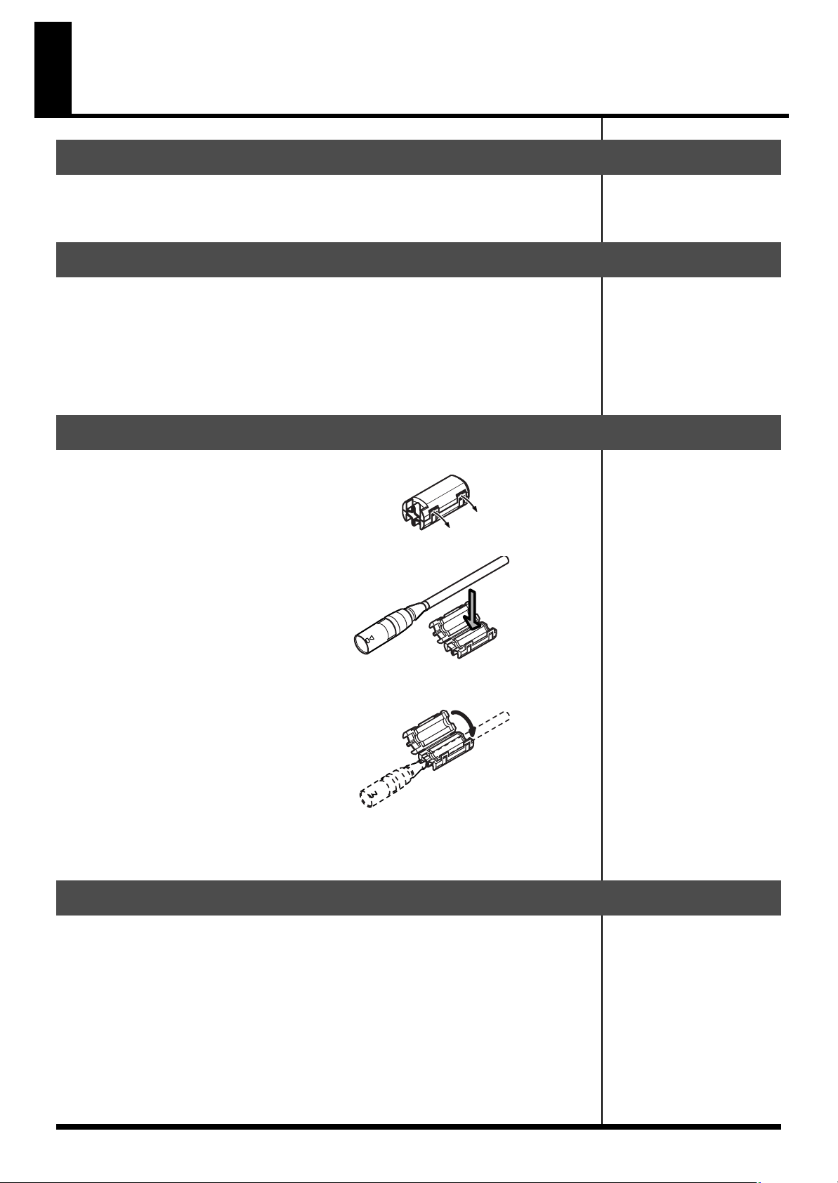
How to Use the Ferrite Cores
1.
Spread open the tabs and open the ferrite core.
2.
Attach the ferrite core near the XLR connector on the AES/EBU cable.
3.
Close the ferrite core by squeezing together the two halves until you hear
them click into place.
4.
Connect the plug that has the ferrite core attached near it to the AES/EBU
connector on the SO-AES4.
Main Features
• 4-channel output of AES/EBU-compliant digital audio
• Built-in sample rate converter providing high sound quality
• Word-clock input and output connectors for support for synchronization with an
external word clock and synchronization with multiple SO-AES4 modules
• Support for a variety of sampling frequencies, up to a maximum of 96 kHz
4
Page 5

Names of Things and What They Do
1
2
5
6
8
3
4
7
9
1
AES/EBU output jacks
These jacks are for output of digital audio conforming to the AES/EBU standard.
Use cables that meet AES/EBU standards.
2
Clock-source switch
This switches the word-clock source. The clock-source indicator displays the current
word-clock source.
3
Clock-source indicator
This indicates the current word-clock source.
Display Description
INT S-4000S internal clock (fixed at 96 kHz)
EXT (W.CLK) Word clock input to the WORD CLK input jack (maximum 96 kHz)
SRC SO-AES4 internal clock (switchable to 44.1 kHz, 48 kHz, or 96 kHz)
The SO-AES4 does not support
double-wire operation.
Changing clock source or
sampling frequency may cause
noise. To avoid the noise,
please use [MUTE ALL
OUTPUTS] button on the S-
4000S while changing clock
source or sampling frequency.
4
Sampling-frequency switch
This changes the sampling frequency when the clock source is SRC.
The current sampling frequency is displayed by the sampling-frequency indicator.
5
Sampling-frequency indicator
This indicates the current sampling frequency.
6
Word-clock input jack
This is a BNC connector for input of an external word clock. It supports sampling
frequencies up to a maximum of 96 kHz.
To change the switch setting,
use a blunt-tipped instrument
such as a ball-point pen,
mechanical pencil, etc.
A signal level of word-clock
source must be within 5Vp-p±
5%.
5
Page 6

Names of Things and What They Do
7
LOCK indicator
This indicates whether correct synchronization to an external word clock is in effect.
Display
Lighted
Flashing Unable to synchronize
Unlit No input
Description
Correctly synchronized
8
Word-clock output/thru jack
This is a BNC connector for output of the internal clock (INTERNAL or SRC) or for
passing through an external word clock.
When synchronizing multiple SO-AES4 modules, use the included BNC cables to
connect the SO-AES4 modules to one another.
Shown below is an example of synchronization of multiple SO-AES4 modules to an
external word clock.
Word clock source : EXT (W.CLK)
External
Word Clock
included
BNC cable
included
BNC cable
included
BNC cable
If the LOCK indicator flashes
and correct synchronization is
impossible, check the
connection with the word-
clock source device, its
sampling frequency, and the
like.
If the LOCK indicator is unlit
and synchronization is
impossible, check for a broken
cable and make sure the word-
clock source device is working
correctly.
THRU
(75Ω OFF)
THRU
(75Ω OFF)
THRU
(75Ω OFF)
OUT
(75Ω ON)
9
Word-clock output/thru switch (word-clock input terminal-resistor switch)
This switches the functioning of the word-clock OUT/THRU jack.
Also, when the SO-AES4 is functioning as a terminal for an external word clock,
setting the switch to OUT (75Ω ON) enables the terminal resistor and prevents signal
reflection.
State
OUT (75Ω ON)
THRU (75Ω OFF) External word clock allowed to pass through (75Ω terminal resistor
The settings for the clock source and the sampling frequency are stored in memory
on the S-4000 unit.These settings are read automatically after a REAC link has been
established.
Description
Internal clock (S-4000S, SO-AES4) is output (75Ω terminal resistor enabled)
disabled)
When the SO-AES4 is
functioning as an external
word-clock terminal, set the
word-clock output/thru
(OUT/THRU) switch to “OUT
(75Ω ON).”
6
Operation using the S-4000R remote controller or the S-4000RCS remote-control
software is supported for storing and recalling of memory or scenes.
Page 7

Applications
This shows a connection example for sending microphone and line inputs from the
stage (32 channels) to a digital mixer and digital recording device via AES/EBU, and
providing line outputs on the stage for AES/EBU outputs from the digital mixer.
S-4000S Master S-4000S Slave
SISISI SI SI SI SI SI SI
SOSOSO
SO SO SO SO SO SO SO
SI SISO
32ch outputs from stage
(AES/EBU outputs
from SO-AES4)
■ Digital Mixer
32ch Mic/Line inputs
SI-AES4 / SI-AD4
SO-AES4 / SO-DA4
8ch outputs from mixer
Stage
Switching Hub
S-4000S Split
SO SO SO SO SO SO SO SO
8ch outputs from mixer
(to SI-AES4 inputs)
32ch outputs from stage
(AES/EBU outputs
from SO-AES4)
■ Digital Recorder
7
Page 8

Specifications
SO-AES4 4-CHANNEL DIGITAL OUTPUT MODULE
Number of channels
4 (All with sample rate conversion)
Format
AES/EBU (Professional Use) IEC60958-4 (Professional Use) *1
Data length
24 bits
Connectors
XLR3-32 type, W.CLK-IN/OUT: BNC Type
Indicators
Clock Source (INT, EXT, SRC)
LOCK (W.CLK)
Sampling Frequency (96kHz, 48kHz, 44.1kHz)
Dimensions
34.5 (W) x 266.0 (D) x 177.0 (H) mm
1-3/8 (W) x 10-1/2 (D) x 7 (H) inches
Weight
600 g
1 lb 6 oz
Operation Temperature
0 to +40 degrees centigrade
+32 to +104 degrees Fahrenheit
Accessories
BNC Cable
Ferrite Cores
Owner’s Manual
8
* 1: The double wire method doesn't operate.
Page 9

MEMO
9
Page 10

MEMO
10
Page 11

For EU Countries
Page 12

*04457501-04*
 Loading...