

Page 1

OWNER’S MANUAL
Thank you, and congratulations on your choice of the Roland Stereo Keyboard Amplifier
KC-880.
These sections provide important information concerning the proper operation of the unit.
Additionally, in order to feel assured that you have gained a good grasp of every feature
provided by your new unit, owner’s manual should be read in its entirety. The manual should be
saved and kept on hand as a convenient reference.
Before using this unit, carefully read the sections entitled:
• IMPORTANT SAFETY INSTRUCTIONS (p. 3)
• USING THE UNIT SAFELY (p. 4–5)
• IMPORTANT NOTES (p. 6)
Main Features
• A monitor-speaker amplifier for keyboards featuring high-power, completely stereo
specifications
This amp can deliver 320 watts of output (160 W + 160 W), and is equipped with two 12-
inch (30-cm) speakers and two tweeters.
• Features a total of five channels of stereo input
In addition to four-channel input, the amp is equipped with an AUX input jack, enabling
you to connect such devices as a rhythm machine, a CD or MP3 player, or an external mixer.
The unit is provided with an exclusive volume control for AUX input that lets you fine-tune
the volume level
• Easy-to-use stereo effect unit
An effect unit that takes advantage of the stereo specifications to make sounds seem
broader and thicker is built in.
You can easily enjoy chorus, tremolo, and rotary effects familiar to keyboard players.
A built-in reverb also expands the range of possible applications using a microphone.
Control using a footswitch pedal is also possible.
• Monitor feature
A convenient monitor-input feature for using guide clicks (such as synchronizing signals for
a sequencer or a rhythm machine) is built in.
• Built-in Stereo Link feature
A Stereo Link feature for applications that need even higher power is built in (p. 14).
• A full range of output jacks for stereo headphones, line out, and more
The amp is equipped with outputs for headphones, line out, and more, providing high
expandability that can accommodate a variety of applications.
Copyright © 2009 ROLAND CORPORATION
All rights reserved. No part of this publication may be reproduced in any form without the
written permission of ROLAND CORPORATION.
(p. 11).
Page 2
This product complies with the requirements of EMCD 2004/108/EC and LVD 2006/95/EC.
For EU Countries
For Canada
This Class B digital apparatus meets all requirements of the Canadian Interference-Causing Equipment Regulations.
Cet appareil numérique de la classe B respecte toutes les exigences du Règlement sur le matériel brouilleur du Canada.
NOTICE
AVIS
For the USA
FEDERAL COMMUNICATIONS COMMISSION
RADIO FREQUENCY INTERFERENCE STATEMENT
This equipment has been tested and found to comply with the limits for a Class B digital device, pursuant to Part 15 of the FCC Rules.
These limits are designed to provide reasonable protection against harmful interference in a residential installation. This equipment
generates, uses, and can radiate radio frequency energy and, if not installed and used in accordance with the instructions, may cause
harmful interference to radio communications. However, there is no guarantee that interference will not occur in a particular
installation. If this equipment does cause harmful interference to radio or television reception, which can be determined by turning
the equipment o and on, the user is encouraged to try to correct the interference by one or more of the following measures:
– Reorient or relocate the receiving antenna.
– Increase the separation between the equipment and receiver.
– Connect the equipment into an outlet on a circuit dierent from that to which the receiver is connected.
– Consult the dealer or an experienced radio/TV technician for help.
This device complies with Part 15 of the FCC Rules. Operation is subject to the following two conditions:
(1) this device may not cause harmful interference, and
(2) this device must accept any interference received, including interference that may cause undesired operation.
Unauthorized changes or modication to this system can void the users authority to operate this equipment.
This equipment requires shielded interface cables in order to meet FCC class B Limit.
WARNING
This product contains chemicals known to cause cancer, birth defects and other reproductive harm, including lead.
For C.A. US (Proposition 65
)
Page 3
IMPORTANT SAFETY INSTRUCTIONS SAVE THESE INSTRUCTIONS
CAUTION
RISK OF ELECTRIC SHOCK
DO NOT OPEN
ATTENTION: RISQUE DE CHOC ELECTRIQUE NE PAS OUVRIR
CAUTION: TO REDUCE THE RISK OF ELECTRIC SHOCK,
DO NOT REMOVE COVER (OR BACK).
NO USER-SERVICEABLE PARTS INSIDE.
REFER SERVICING TO QUALIFIED SERVICE PERSONNEL.
The lightning ash with arrowhead symbol, within an
equilateral triangle, is intended to alert the user to the presence
of uninsulated “dangerous voltage” within the product’s
enclosure that may be of sucient magnitude to constitute a
risk of electric shock to persons.
The exclamation point within an equilateral triangle is intended
to alert the user to the presence of important operating and
maintenance (servicing) instructions in the literature
accompanying the product.
INSTRUCTIONS PERTAINING TO A RISK OF FIRE, ELECTRIC SHOCK, OR INJURY TO PERSONS.
IMPORTANT SAFETY INSTRUCTIONS
SAVE THESE INSTRUCTIONS
WARNING - When using electric products, basic precautions should always be followed, including the following:
1. Read these instructions.
2. Keep these instructions.
3. Heed all warnings.
4. Follow all instructions.
5. Do not use this apparatus near water.
6. Clean only with a dry cloth.
7. Do not block any of the ventilation openings. Install in
accordance with the manufacturers instructions.
8. Do not install near any heat sources such as radiators, heat
registers, stoves, or other apparatus (including ampliers) that
produce heat.
9. Do not defeat the safety purpose of the polarized or
grounding-type plug. A polarized plug has two blades with one
wider than the other. A grounding type plug has two blades
and a third grounding prong. The wide blade or the third prong
are provided for your safety. If the provided plug does not t
into your outlet, consult an electrician for replacement of the
obsolete outlet.
For the U.K.
WARNING:
IMPORTANT:
As the colours of the wires in the mains lead of this apparatus may not correspond with the coloured markings identifying the
terminals in your plug, proceed as follows:
The wire which is coloured GREEN-AND-YELLOW must be connected to the terminal in the plug which is marked by the letter E or
by the safety earth symbol or coloured GREEN or GREEN-AND-YELLOW.
The wire which is coloured BLUE must be connected to the terminal which is marked with the letter N or coloured BLACK.
The wire which is coloured BROWN must be connected to the terminal which is marked with the letter L or coloured RED.
THIS APPARATUS MUST BE EARTHED
THE WIRES IN THIS MAINS LEAD ARE COLOURED IN ACCORDANCE WITH THE FOLLOWING CODE.
GREEN-AND-YELLOW: EARTH, BLUE: NEUTRAL, BROWN: LIVE
10. Protect the power cord from being walked on or pinched
particularly at plugs, convenience receptacles, and the point
where they exit from the apparatus.
11. Only use attachments/accessories specied by
the manufacturer.
12. Unplug this apparatus during lightning storms or when
unused for long periods of time.
13. Refer all servicing to qualied service personnel. Servicing is
required when the apparatus has been damaged in any way,
such as power-supply cord or plug is damaged, liquid has been
spilled or objects have fallen into the apparatus, the apparatus
has been exposed to rain or moisture, does not operate
normally, or has been dropped.
WARNING: To reduce the risk of re or electric shock, do not expose this apparatus to rain or moisture.
Page 4
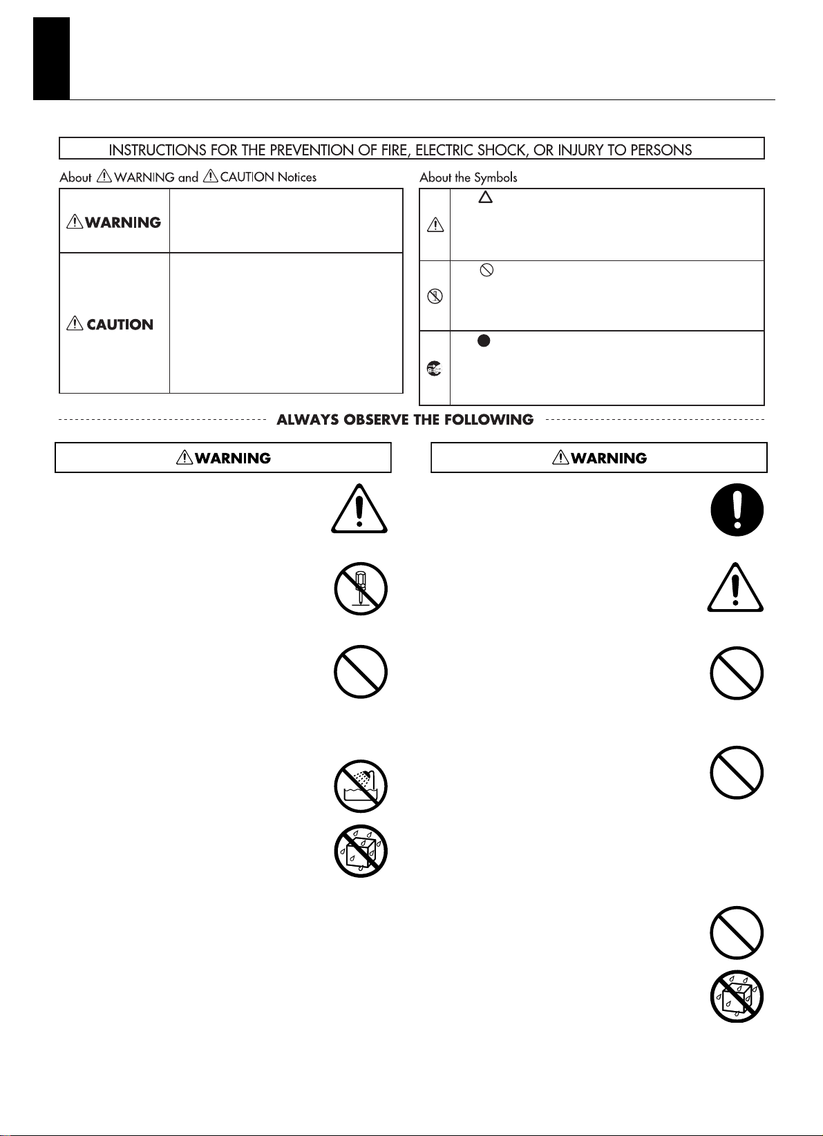
USING THE UNIT SAFELY
Used for instructions intended to alert the
user to the risk of injury or material
damage should the unit be used
improperly.
* Material damage refers to damage or
other adverse eects caused with
respect to the home and all its
furnishings, as well to domestic animals
or pets.
Used for instructions intended to alert the
user to the risk of death or severe injury
should the unit be used improperly.
The symbol alerts the user to things that must be
carried out. The specic thing that must be done is
indicated by the design contained within the circle. In the
case of the symbol at left, it means that the power-cord
plug must be unplugged from the outlet.
The symbol alerts the user to important instructions or
warnings.The specic meaning of the symbol is
determined by the design contained within the triangle. In
the case of the symbol at left, it is used for general
cautions, warnings, or alerts to danger.
The symbol alerts the user to items that must never be
carried out (are forbidden). The specic thing that must not
be done is indicated by the design contained within the
circle. In the case of the symbol at left, it means that the
unit must never be disassembled.
001-50
• Connect mains plug of this model to a mains
socket outlet with a protective earthing
connection.
................................................................................................................................
002a
• Do not open or perform any internal
modifications on the unit.
................................................................................................................................
003
• Do not attempt to repair the unit, or replace parts
within it (except when this manual provides
specific instructions directing you to do so). Refer
all servicing to your retailer, the nearest Roland
Service Center, or an authorized Roland
distributor, as listed on the “Information” page.
................................................................................................................................
004
• Never install the unit in any of the following
locations.
• Subject to temperature extremes (e.g., direct
sunlight in an enclosed vehicle, near a heating
duct, on top of heat-generating equipment); or
are
• Damp (e.g., baths, washrooms, on wet floors);
or are
• Exposed to steam or smoke; or are
• Subject to salt exposure; or are
• Humid; or are
• Exposed to rain; or are
• Dusty or sandy; or are
• Subject to high levels of vibration and
................................................................................................................................
4
shakiness.
007
• Make sure you always have the unit placed so it is
level and sure to remain stable. Never place it on
stands that could wobble, or on inclined surfaces.
.................................................................................................................................
008a
• The unit should be connected to a power supply
only of the type described in the operating
instructions, or as marked on the rear side of
unit.
.................................................................................................................................
009
• Do not excessively twist or bend the power cord,
nor place heavy objects on it. Doing so can
damage the cord, producing severed elements
and short circuits. Damaged cords are fire and
shock hazards!
.................................................................................................................................
010
• This unit, either alone or in combination with an
amplifier and headphones or speakers, may be
capable of producing sound levels that could
cause permanent hearing loss. Do not operate for
a long period of time at a high volume level, or at
a level that is uncomfortable. If you experience
any hearing loss or ringing in the ears, you should
immediately stop using the unit, and consult an
audiologist.
.................................................................................................................................
011
• Do not allow any objects (e.g., flammable
material, coins, pins); or liquids of any kind (water,
soft drinks, etc.) to penetrate the unit.
.................................................................................................................................
Page 5
USING THE UNIT SAFELY
012a
• Immediately turn the power off, remove the
power cord from the outlet, and request
servicing by your retailer, the nearest Roland
Service Center, or an authorized Roland
distributor, as listed on the “Information” page
when:
• The power-supply cord or the plug has been
damaged; or
• If smoke or unusual odor occurs
• Objects have fallen into, or liquid has been
spilled onto the unit; or
• The unit has been exposed to rain (or
otherwise has become wet); or
• The unit does not appear to operate normally
or exhibits a marked change in performance.
................................................................................................................................
013
• In households with small children, an adult
should provide supervision until the child is
capable of following all the rules essential for the
safe operation of the unit.
................................................................................................................................
014
• Protect the unit from strong impact.
(Do not drop it!)
................................................................................................................................
015
• Do not force the unit’s power-supply cord to
share an outlet with an unreasonable number of
other devices. Be especially careful when using
extension cords—the total power used by all
devices you have connected to the extension
cord’s outlet must never exceed the power rating
(watts/amperes) for the extension cord. Excessive
loads can cause the insulation on the cord to heat
up and eventually melt through.
................................................................................................................................
016
• Before using the unit in a foreign country,
consult with your retailer, the nearest Roland
Service Center, or an authorized Roland
distributor, as listed on the “Information” page.
................................................................................................................................
026
• Do not put anything that contains water (e.g.,
flower vases) on this unit. Also, avoid the use of
insecticides, perfumes, alcohol, nail polish, spray
cans, etc., near the unit. Swiftly wipe away any
liquid that spills on the unit using a dry, soft
cloth.
102a
• Always grasp only the plug on the power-supply
cord when plugging into, or unplugging from an
outlet.
.................................................................................................................................
103a
• At regular intervals, you should unplug the power
plug and clean it by using a dry cloth to wipe all
dust and other accumulations away from its
prongs. Also, disconnect the power plug from the
power outlet whenever the unit is to remain
unused for an extended period of time. Any
accumulation of dust between the power plug
and the power outlet can result in poor insulation
and lead to fire.
.................................................................................................................................
104
• Try to prevent cords and cables from becoming
entangled. Also, all cords and cables should be
placed so they are out of the reach of children.
.................................................................................................................................
105b
• If the unit could become a hazard if it moves, all
caster wheels should be removed once the unit
has been placed at the place of installation, or has
been loaded onto a vehicle.
.................................................................................................................................
106
• Never climb on top of, nor place heavy objects on
the unit.
.................................................................................................................................
107a
• Never handle the power cord or its plug with wet
hands when plugging into, or unplugging from,
an outlet.
.................................................................................................................................
108a
• Before moving the unit, disconnect the power
plug from the outlet, and pull out all cords from
external devices.
.................................................................................................................................
109a
• Before cleaning the unit, turn off the power and
unplug the power cord from the outlet.
.................................................................................................................................
110a
• Whenever you suspect the possibility of lightning
in your area, pull the plug on the power cord out
of the outlet.
101a
• The unit should be located so that its location or
position does not interfere with its proper
ventilation.
................................................................................................................................
.................................................................................................................................
121
• Do not remove the speaker grille and speaker by
any means. Speaker not user replaceable. Shock
hazardous voltages and currents are present
inside the enclosure.
.................................................................................................................................
5
Page 6

IMPORTANT NOTES
Power Supply
301
• Do not connect this unit to same electrical outlet that is being
used by an electrical appliance that is controlled by an
inverter (such as a refrigerator, washing machine, microwave
oven, or air conditioner), or that contains a motor. Depending
on the way in which the electrical appliance is used, power
supply noise may cause this unit to malfunction or may
produce audible noise. If it is not practical to use a separate
electrical outlet, connect a power supply noise filter between
this unit and the electrical outlet.
307
• Before connecting this unit to other devices, turn off the
power to all units. This will help prevent malfunctions and/or
damage to speakers or other devices.
308
• Although the LEDs are switched off when the POWER switch
is switched off, this does not mean that the unit has been
completely disconnected from the source of power. If you
need to turn off the power completely, first turn off the
POWER switch, then unplug the power cord from the power
outlet. For this reason, the outlet into which you choose to
connect the power cord’s plug should be one that is within
easy reach and readily accessible.
Placement
351
• Using the unit near power amplifiers (or other equipment
containing large power transformers) may induce hum. To
alleviate the problem, change the orientation of this unit; or
move it farther away from the source of interference.
352a
• This device may interfere with radio and television reception.
Do not use this device in the vicinity of such receivers.
352b
• Noise may be produced if wireless communications devices,
such as cell phones, are operated in the vicinity of this unit.
Such noise could occur when receiving or initiating a call, or
while conversing. Should you experience such problems, you
should relocate such wireless devices so they are at a greater
distance from this unit, or switch them off.
354b
• Do not expose the unit to direct sunlight, place it near
devices that radiate heat, leave it inside an enclosed vehicle,
or otherwise subject it to temperature extremes. Also, do not
allow lighting devices that normally are used while their light
source is very close to the unit (such as a piano light), or
powerful spotlights to shine upon the same area of the unit
for extended periods of time. Excessive heat can deform or
discolor the unit.
355b
• When moved from one location to another where the
temperature and/or humidity is very different, water droplets
(condensation) may form inside the unit. Damage or
malfunction may result if you attempt to use the unit in this
condition. Therefore, before using the unit, you must allow it
to stand for several hours, until the condensation has
completely evaporated.
356
• Do not allow rubber, vinyl, or similar materials to remain on
the unit for long periods of time. Such objects can discolor or
otherwise harmfully affect the finish.
359
• Do not paste stickers, decals, or the like to this instrument.
Peeling such matter off the instrument may damage the
exterior finish.
360
• Depending on the material and temperature of the surface
on which you place the unit, its rubber feet may discolor or
mar the surface.
You can place a piece of felt or cloth under the rubber feet to
prevent this from happening. If you do so, please make sure
that the unit will not slip or move accidentally.
Maintenance
401b
• To clean the unit, use a dry, soft cloth; or one that is slightly
dampened. Try to wipe the entire surface using an equal
amount of strength, moving the cloth along with the grain of
the wood. Rubbing too hard in the same area can damage
the finish.
402
• Never use benzine, thinners, alcohol or solvents of any kind,
to avoid the possibility of discoloration and/or deformation.
Additional Precautions
553
• Use a reasonable amount of care when using the unit’s
buttons, sliders, or other controls; and when using its jacks
and connectors. Rough handling can lead to malfunctions.
556
• When connecting / disconnecting all cables, grasp the
connector itself—never pull on the cable. This way you will
avoid causing shorts, or damage to the cable’s internal
elements.
557
• A small amount of heat will radiate from the unit during
normal operation.
558a
• To avoid disturbing your neighbors, try to keep the unit’s
volume at reasonable levels. You may prefer to use
headphones, so you do not need to be concerned about
those around you (especially when it is late at night).
559a
• When you need to transport the unit, package it in the box
(including padding) that it came in, if possible. Otherwise,
you will need to use equivalent packaging materials.
562
• Some connection cables contain resistors. Do not use cables
that incorporate resistors for connecting to this unit. The use
of such cables can cause the sound level to be extremely low,
or impossible to hear. For information on cable specifications,
contact the manufacturer of the cable.
• Wrap the power cord around the cord hook when
transporting or storing the unit.
6
Page 7

Important Notes When Moving the Unit
This equipment is heavy (weighing 44 kilograms), so to prevent
injury and other safety hazards due to accidental toppling, drops,
or falls, at least two persons should work together to carry the
unit when moving it.
fig.unpan.eps
When moving this equipment, carry it while securely gripping
the left and right handles as shown in the figure.
fig.handle.eps
Use and Handling of the Casters
The KC-880 comes with casters, which can be useful when
moving the unit.
Attaching and Removing the Casters
When attaching or removing the casters, give attention to the
following points.
• Carry out the operation at a location that is level and stable.
• To ensure safety, at least two persons should work together
to carry out the operation.
• Exercise care to keep fingers or feet from being pinched or
pinned.
• When attaching or removing the casters, to avoid damaging
the unit or the floor surface, place stacked newspapers or the
like under the unit.
• When placing the unit on the floor on its side, handle with
care to avoid dropping it, or allowing it to fall or tip over.
ig.caster.eps
Using the included casters can be convenient on level surfaces.
1. Place the KC-880 on the floor on its side as
shown in the figure.
2. Attach the casters to the unit (or detach the
casters).
3. Return the unit to its upright position.
Turning the Power On and Off
* Once the connections have been completed, turn on power to your
various devices in the order specified. By turning on devices in the
wrong order, you risk causing malfunction and/or damage to
speakers and other devices.
* Before switching off the power, lower the volume on each of the
devices in your system and then TURN OFF the devices in the
reverse order to which they were switched on.
1. Make sure that all volume controls on the KC-
880 and connected devices are set to 0.
2. Turn on all the devices connected to the KC-
880’s input jacks (CH 1 through CH 4 and AUX
IN/MONITOR IN).
3. Turn on the KC-880.
4. Switch on any equipment connected to the
KC-880’s LINE OUT jacks.
5. Adjust the volume levels for the devices.
* This unit is equipped with a protection circuit. A brief interval (a few
seconds) after power up is required before the unit will operate
normally. For protection from sudden big sound, always make sure
to have the volume level turned down before switching on power.
Even with the volume all the way down, you may still hear some
sound when the power is switched on, but this is normal, and does
not indicate a malfunction.
* If you need to turn off the power completely, first turn off the
[POWER] switch, then unplug the power cord from the power outlet.
Refer to
“Power Supply” (p. 6).
7
Page 8

Quick Guide
on
The Quick Guide describes required settings and basic operations.
Getting Ready
Making the Connections
For more information about making the connections, refer to
“Connect your KC-880” (p. 9).
1. Make sure all devices are turned off.
2. Connect the external devices.
3. Turn down all volume controls on the KC-880
to zero.
fig.QG-01.eps
4. Place the EQUALIZER controls at the center
position (0).
fig.QG-02.eps
5. Switch off all [EFX] buttons.
fig.QG-03.eps
Try Playing Sound from the Built-in Speakers
1. Adjust each channel’s volume knob to its
center setting (5).
If you’re using a microphone, turn the CH1 volume knob to
the “MIC” range.
Lower the volume levels for channels you’re not using.
fig.QG-06.eps
When using a mic
2. While playing sound on the connected
devices, slowly turn the [VOLUME] knob to
adjust the overall volume level.
fig.QG-07.eps
3. Use the volume knobs for the respective
channels to adjust the volume balance for the
connected devices.
fig.QG-08.eps
6. Switch off the AUX IN/MONITOR IN [MUTE]
button.
fig.QG-04.eps
on
Switch on the Power
* Once the connections have been completed, turn on power to your
various devices in the order specified. By turning on devices in the
wrong order, you risk causing malfunction and/or damage to
speakers and other devices.
1. Turn on the devices connected to the input
jacks.
2. Turn on the KC-880.
fig.QG-05.eps
3. Turn on the devices connected to the output
jacks.
Turn off the power in the reverse order.
4. Use the [VOLUME] knob and the EQUALIZER
controls to adjust the overall volume level
and sound quality.
fig.QG-09.eps
Try Applying Built-in Effects
1. Press the [EFX] button for the channel to
which you want to apply the effect.
fig.QG-10.eps
on
2. Use the [EFX] knob to adjust the effect and its
depth.
fig.QG-11.eps
8
Page 9

Connect your KC-880
STEREO
LINK OUT
STEREO
LINK IN
Foot switches
KC-880
Mic
Headphones
Portable
audio
player
Rhythm machine
Electronic
drum
Sound module
Digital piano
Synthesizer
CD player
PA system
Recorder
WhiteRed WhiteRed
FS-5L
FS-5L FS-6
PCS-31 PCS-31
* For information on the switch settings, refer to page 12.
Refer to the following diagram and connect the KC-880 to the external equipment you are using.
fig.connect.eps
* To prevent malfunction and/or damage to speakers or other
devices, always turn down the volume, and turn off the power on all
devices before making any connections.
Set all of the KC-880’s channel volume knobs (CH 1, CH 2, CH 3 and
CH 4) and AUX IN/MONITOR IN [LEVEL] knob as well as the
[VOLUME] knob to zero.
* The pin assignment for the XLR type connectors is as shown below.
Before making any connections, make sure that this pin assignment
is compatible with that of all your other devices.
fig.XLR.eps
* When connection cables with resistors are used, the volume level of
equipment connected to the inputs (CH 1 through CH 4, AUX IN/
MONITOR IN and STEREO LINK IN) may be low.
If this happens, use connection cables that do not contain resistors.
* Howling could be produced depending on the location of
microphones relative to speakers. This can be remedied by:
1. Changing the orientation of the microphone.
2. Relocating microphone at a greater distance from speakers.
3. Lowering volume levels.
9
Page 10

Names of Things and What They Do
1
2
1
2
1
2
1
2
4
3
5
On
Lower position
O
Upper position
Switching Buttons On and O
CH1–CH4
These adjust the volume levels and switch the internal effect unit on or off for devices
connected to the respective channels (CH).
Volume knob
This adjusts the volume level for the device connected to the respective channel.
Turning the knob clockwise increases the volume.
Channel 1 (CH1) supports a microphone connection.
When you’re using a microphone, set the knob at the range labeled “MIC.”
* Leave the volume knobs for unused channels set at 0 (zero).
[EFX] Button
This lets you switch the internal effect units (EFX) on or off for each individual channel.
When on (pressed in), the effect is applied to the device connected to the
corresponding channel.
* When the [EFX] knob is set at the OFF position, no effects are applied, regardless
of the settings of any [EFX] buttons.
EQUALIZER
This adjusts the tone of speaker and headphones output.
These controls are normally left set at 0 (zero).
Turning clockwise makes the corresponding frequency
range more prominent.
Turning counterclockwise reduces the intensity of the
frequency range.
[LOW] Knob
This adjusts the tone of the bass range.
[MIDDLE] Knob
This adjusts the tone of the middle range.
[HIGH] Knob
This adjusts the tone of the treble range.
EFX
You can apply the built-in effects to devices connected to channels 1 through 4 (CH1–CH4).
You can select any one from among a total of four types.
[EFX] Knob
You can switch among the four types of effects and adjust the
intensity of the effect by changing the position of the knob.
REVERB:
This effect imparts lingering reverberations for a sound like a
performance in a concert hall.
This is a stereo reverb that adds breadth.
The positioning of the knob adjusts the volume of the reverb.
It’s also ideal for a microphone connected to channel 1 (CH1).
CHORUS:
This effect makes the sound fuller and broader.
It’s optimal for the tones of instruments such as strings.
The positioning of the knob adjusts the depth of the effect.
TREMOLO:
This effect produces cyclical changes in the volume level.
This is optimal for the tones of instruments such as electric pianos.
The positioning of the knob adjusts the depth and speed of the
tremolo volume changes.
ROTARY:
This effect imparts undulations and a unique sense of rotation
to the sound.
It’s optimal for the tones of instruments such as organs.
The positioning of the knob adjusts the depth of the effect.
* This effect is applied to devices connected to channels whose
[EFX] buttons are switched on.
* The scale indications for REVERB, CHORUS, TREMOLO, and
ROTARY are merely a general guide. Adjust while checking the
effect with your own ear.
[SPEED] Button (ROTARY)
This changes the speed of the ROTARY effect.
Pressing the button in makes the undulations faster.
* When this is switched, the speed of rotation changes smoothly.
* The [SPEED] button affects only the ROTARY effect.
EFX Indicators
The left and right indicators flash in alternately in time with the
speed of the effect.
* When REVERB or CHORUS is selected, both indicators light up.
* When the effect is turned off using a footswitch pedal, both
indicators go out.
Control Panel
1
2
8
9
10
3
10
4
5
Page 11

Names of Things and What They Do
13
14
121110
6 8
7
9
AUX IN/MONITOR IN
This adjusts the volume level and other settings of a device connected to the AUX IN/MONITOR IN.
You can also use this to input guide clicks from a drum machine, metronome, or other such device (monitor feature).
[LEVEL] Knob
This adjusts the volume level of a device connected to AUX IN/
MONITOR IN.
Turning the knob clockwise increases the volume.
* Leave the [LEVEL] knob set at 0 (zero) when you’re not using
AUX IN/MONITOR IN.
[MUTE] Buttons
These make the setting for using AUX IN as MONITOR IN.
Switching on the [MUTE] buttons stops output from the unit’s
speakers or LINE OUT of the sound from the device connected to
AUX IN.
This can be useful when you’re using clicks or other guide sounds
from a metronome or other equipment.
SPEAKER:
Switching this on mutes output from the unit’s speakers of the
device connected to AUX IN.
LINE OUT:
Switching this on mutes output from the LINE OUT of the
device connected to AUX IN.
* Sound is always output to headphones, regardless of the
settings of the [MUTE] buttons.
What’s the Monitor Feature?
During stage performances, this feature lets the performer input guide
clicks needed for playing in sync with a sequencer or other sounds that
people other than the performer are not meant to hear, and play them
so that only the performer can monitor them.
The KC-880 uses a mute feature that lets you select and mute out the
output of audio signals input to AUX IN/MONITOR IN.
Usage Example 1: Using the KC-880 as a dedicated monitorspeaker amplifier in a public address (PA) system (p. 15)
Input the guide clicks or the like to AUX IN/MONITOR IN and switch
on the MUTE [LINE OUT] button.
The guide clicks are output from the built-in speakers and
headphones, but not from the LINE OUT jack.
* The performer monitors the sound using the built-in speakers.
Usage Example 2: Using the KC-880 as the main PA device (p. 15)
Input the guide clicks or the like to AUX IN/MONITOR IN on the unit
and switch on the MUTE [SPEAKER] button.
The guide clicks are output from the LINE OUT jack and
headphones, but not from the built-in speakers.
* The performer monitors the sound using headphones.
VOLUME
[VOLUME] Knob
This adjusts the volume level of speaker output.
POWER
[POWER] Switch
This switches the unit’s power on and off.
When it’s on, the POWER indicator lights up.
POWER Indicator
PHONES
[PHONES] Knob
This adjusts the volume level of headphones output.
12
11
13
14
6
7
11
Page 12

Names of Things and What They Do
1
2 2 2
6
7
7
8
PHONES
PHONES Jack
Accepts connection of stereo headphones.
This not only enables use for practice at night or
other situations where quiet is required, but also
lets you monitor guide clicks.
* Connecting headphones doesn’t cut off the
sound from the speaker.
* Always be sure to lower the [PHONES] knob to 0
(zero) whenever connecting headphones.
AUX IN/MONITOR IN
Here is where you can connect a CD or MP3 player, an external mixer, or other line
equipment.
You can also use this as MONITOR IN for connecting a drum machine, metronome, or
other device for producing guide clicks.
AUX IN/MONITOR IN (AUX 1–3) Jacks
Here is where you can connect a CD or MP3 player, an external mixer, or other
line equipment (-20 dBu).
Three types of jacks are provided (1/4” phone, RCA phono, and stereo mini), and
mixing is carried out internally.
Simultaneous connections are possible, but the volume level will be lower
compared to single use.
FOOT SW
FOOT SW Jack
Connecting a footswitch pedal enables you to switch the internal effects (EFX) on
and off and adjust the speed of the rotary effect using your foot.
An optionally available latch-type footswitch pedal (BOSS FS-5L or FS-6, available
separately) and cable (Roland PCS-31, available separately) are required.
EFX ON/OFF:
Each press of the footswitch pedal switches the internal effects on or off.
SPEED (SLOW/FAST):
Switching on the footswitch pedal sets the rotary at high speed (FAST).
* When a monaural cable is connected, EFX is switched on and off using the
footswitch pedal. The SPEED setting is changed using the control panel.
* When EFX has been switched off using the footswitch pedal, effects remain off
even if the [EFX] knob on the control panel is operated.
* Varying the setting of the [SPEED] button on the control panel changes the
speed of the rotary effect, regardless of any SPEED setting made using the
footswitch pedal. This may result in the footswitch pedal and the [SPEED]
button being at different settings, but this isn’t a malfunction. Depressing the
footswitch pedal once clears this state (but this doesn’t change the speed of
the rotary effect).
AC Cord Cord Hook (p. 6)
Jack Panel
1
2
12
PCS-31
ON/OFFSPEED
* Set the FS-5L’s polarity
switch as shown below.
PCS-31
WhiteRed
SPEED ON/OFF
* When making the connection using
the FS-6, set the POLARITY and
MODE switches as shown below.
BA
6
WhiteRed
Page 13

Names of Things and What They Do
10
4
3
5 5 5
9
LINE OUT
Here you can connect PA systems, recording decks, and
other such equipment.
LINE OUT Connectors and Jacks
You can connect mixers, recorders, and other such
equipment here.
XLR connectors supporting balanced output and
1/4” phone jacks are provided. For monaural output,
you should use the use 1/4” phone jack.
You can use the XLR connectors and 1/4” phone
jacks at the same time.
* The EQUALIZER controls and the [VOLUME]
knobs have no effect on LINE OUT.
GND LIFT Switch
Connecting an external device to an XLR-type LINE
OUT connector may produce loop hum.
If this happens, changing the setting of this switch
may alleviate the problem.
This is normally left set to OFF.
ON: This isolates the first connector from the unit’s
ground.
OFF: This connects the first connector to the unit’s
ground.
STEREO LINK
You can use this when you’re using two KC-880 units to form a stereo system that has
even higher output (p. 14).
You connect each other’s LINK IN and LINK OUT jacks using one or two 1/4
” phone
cables.
Using two 1/4
” phone cables enables you to use all inputs on the KC-880 units, for a
total of eight channel inputs and two AUX IN systems.
LINK IN Jack
Connect this to the LINK OUT L or LINK OUT R jack on the other KC-880.
When the LINK OUT L jack is connected: The left-channel signal is output from
the unit’s speakers. (On the other KC-880, the right-channel signal is output.)
When the LINK OUT R jack is connected: The right-channel signal is output
from the unit’s speakers. (On the other KC-880, the left-channel signal is output.)
LINK OUT L/R Jacks
Connect either one of the jacks to the LINK IN jack on the other KC-880.
Whether the unit handles the left or right channel is determined by the jack you
use.
When connected to the LINK OUT L jack: The right-channel signal is output
from the unit. (On the other KC-880, the left-channel signal is output.)
When connected to the LINK OUT R jack: The left-channel signal is output
from the unit. (On the other KC-880, the right-channel signal is output.)
CH1–CH4 Input
You can connect up to four devices, including keyboards or other electronic instruments, or line devices such as a CD player, or a microphone (CH1 only).
CH 1 BALANCED (XLR) Input Connector
Here is where you can connect a microphone. This supports XLRtype balanced input.
* No phantom power feature is provided.
CH 1 Input Jacks
Here you can connect a keyboard or other electronic instrument, a
line device such as a CD player (-20 dBu), or a microphone (-50 dBu).
Equipment with monaural output or microphone is connected to L/
MONO.
* Switching between a line device and a microphone is
accomplished using the CH1 volume knob on the control panel.
* You can connect two microphones to the L/MONO and R jacks
at the same time, but the volume level may drop.
CH 2–4 Input Jacks
Here you can connect keyboards or other electronic instruments, or
line devices such as a CD player (-20 dBu).
Equipment with monaural output is connected to L/MONO.
3
4
5
7
8
9
10
13
Page 14

Stereo Link
What’s Stereo Link?
This lets you use two KC-880 units to form a stereo PA system having a high output of 320 + 320 watts.
This feature is called “Stereo Link.”
Two different connection methods are available for Stereo Link: basic connection using one 1/4” phone cable, and advanced connection
using two 1/4” phone cables.
Making the connections using two 1/4” phone cables enables you to take full advantage of the mixing features of the two KC-880 units.
Examples of Connections
1. Basic Stereo Link
■ If you want to connect input sources
to the KC-880 (L)
Up to five input devices can be connected.
fig.stereolink-1.eps
CH 1-4 AUX IN
KC-880
(L)
STEREO LINK
OUT R
KC-880
(R)
STEREO LINK
IN
1. Connect the devices to the KC-880 (L).
2. Connect the STEREO LINK OUT R jack on the
KC-880 (L) and the STEREO LINK IN jack on
the KC-880 (R).
3. Turn on both KC-880 (L) and KC-880 (R).
4. Adjust the volume levels on all devices.
2. Advanced Stereo Link
This arrangement lets you play in stereo, making maximum use
of the two KC-880s’ mixer functions (with ten inputs).
fig.stereolink-2.eps
CH 1-4 AUX IN CH 1-4 AUX IN
KC-880
(L)
STEREO LINKINSTEREO LINK
OUT R
STEREO LINK
KC-880
IN
(R)
STEREO LINK
OUT L
1. Connect the devices to the KC-880 (L) and KC-
880 (R).
2. Connect the STEREO LINK OUT R jack on the
KC-880 (L) and the STEREO LINK IN jack on
the KC-880 (R).
3. Connect the STEREO LINK OUT L jack on the
KC-880 (R) and the STEREO LINK IN jack on
the KC-880 (L).
5. Adjust the KC-880 (L) and KC-880 (R) volume
levels separately using their [VOLUME]
knobs.
■ If you want to connect input sources
to the KC-880 (R)
As described in step 2 of example 1, connect the R side’s STEREO
LINK OUT L jack to the L side’s STEREO LINK IN jack.
4. Turn on both KC-880 (L) and KC-880 (R).
5. Adjust the volume levels on all devices.
6. Adjust the KC-880 (L) and KC-880 (R) volume
levels separately using their [VOLUME]
knobs.
About the Volume and Tone Settings
Adjust the R and L volume levels separately using their [VOLUME] knobs.
You can adjust the EQUALIZER ([LOW]/[MIDDLE]/[HIGH] knobs) independently for the L and R sides.
Basically, they should be set to the same positions, but you can adjust each one as necessary to suit the needs of a particular setup.
14
Page 15

Connection Example
KC-880
Mic
Headphones
Rhythm machine
(guide clicks)
Digital piano
Switch on the MUTE [SPEAKER] button.
CH1
AUX IN/
MONITOR IN
PHONES
CH2
Connection Example 1—Use as a Monitor
Here is an example of a setup for live performances using a PA system. It lets you monitor guide clicks by using the KC-880’s monitor
feature to play the guide sound from the unit’s speakers without outputting the clicks to the PA system.
fig.connect-ex1.eps
(guide clicks)
Digital piano
CH2
CH1
MicRhythm machine
PA system
AUX IN/
MONITOR IN
LINE OUT
KC-880
Switch on the MUTE [LINE OUT] button.
Connection Example 2—Use as a Main Speaker
Here is an example of a setup for live performances that uses the KC-880 as the main speaker.
It lets you monitor guide clicks by using the KC-880’s monitor feature to play the guide sound from headphones connected to the unit
without outputting the clicks from the built-in speakers.
fig.connect-ex2.eps
Connection Example 3—Use as a Simple PA System
This is an example of a setup that connects two KC-880 units via Stereo Link for use as a simple PA system.
fig.connect-ex2.eps
Electric
guitar
Portable
audio
player
processor
Eects
MONITOR IN
Electronic
drum
AUX IN/
Synthesizer
Keyborard
Mic
CH3CH4
CH1
Stereo Link
(p. 14)
KC-880 KC-880
Mic
CH1CH2 CH2
15
Page 16

Block Diagram
block.eps
CH1
BALANCED
CH1
AUX IN/
MONITOR IN
CH2
CH3
CH4
AUX 1
AUX 2
AUX 3
(STEREO)
STEREO
LINK IN
(MONO)
L/R
L/R
L/R
L/R
L/R
L/R
EFX
CH 1
EFX
CH 2
EFX
CH 3
EFX
CH 4
LEVEL
MUTE
SPEAKER
LINE OUT
EFX (L/R)
(L/R)
PHONES
SPEAKER
(L/R)
LINE OUT
(L/R)
LOW
EQUALIZER
EQUALIZER
MIDDLE
TYPE
EFX
HIGH
SPEED
VOLUME
HPF
STEREO
LINK
L
R
LPF
HPF
LPF
POWER AMP
PHONES
GND LIFT
TWEETER L
WOOFER L
TWEETER R
WOOFER R
PHONES
(STEREO)
LINE OUT
XLR
L/R
LINE OUT
L/R
STEREO
LINK OUT
L/R
FOOT SW
TIP: ON/OFF
RING: SPEED
Troubleshooting
If the unit doesn’t work the way you think it should, then before you do anything else, first check the following points. If these checks fail to
determine the cause, consult your retailer or the nearest Roland Service Center.
Problem Cause
No power.
Is the power cord correctly plugged in to a
power outlet?
Is the external equipment connected
correctly?
Are the [VOLUME] knob and the volume
knobs for the respective channels adjusted
correctly?
No sound.
Are the AUX IN/MONITOR IN [MUTE]
buttons switched on?
If the problem of no sound persists, contact
your retailer or the nearest Roland Service
Center.
Are the [VOLUME] knob and the volume
knobs for the respective channels turned
Sound is
up too high?
distorted or
noisy.
Is the input signal from the device
connected to the mixer at an appropriate
level?
Problem Cause
Are the [VOLUME] knob and the volume
knobs for the respective channels adjusted
correctly?
Are connections made to both the XLRtype and 1/4” phone connectors for
channel 1 (CH1)?
Low sound.
Use only one of the two connectors.
Is the input signal from the device
connected to the mixer at an appropriate
level?
Are two or more devices connected to AUX
IN?
Are the [EFX] buttons for the respective
channels switched on?
Effects are not
applied.
Is the [EFX] knob adjusted correctly?
Have effects been turned off using the
footswitch pedal?
16
Page 17

Main Specifications
KC-880: STEREO KEYBOARD AMPLIFIER
Rated Power
Output
Nominal Input
Level (@1 kHz)
Nominal Output
Level (@1 kHz)
Speakers
Controls
320W (160W +160W)
CH1 (MIC/LINE): -50–-20 dBu
CH2–4 (LINE): -20 dBu
AUX IN/MONITOR IN: -20 dBu
STEREO LINK IN: 0 dBu
LINE OUT (XLR type, Phone type): +4 dBu
STEREO LINK OUT: 0 dBu
* 0 dBu = 0.775 Vrms
30 cm (12 inches) Woofer x 2
Horn Tweeter x 2
<CHANNEL CONTROL>
CH1
Volume Knob
EFX Button
CH2
Volume Knob
EFX Button
CH3
Volume Knob
EFX Button
CH4
Volume Knob
EFX Button
EFX Knob
SPEED Button
<MASTER CONTROL>
AUX IN/MONITOR IN
LEVEL Knob
MUTE
SPEAKER Button
LINE OUT Button
EQUALIZER
LOW Knob
MIDDLE Knob
HIGH Knob
PHONES VOLUME Knob
VOLUME Knob
POWER Switch
GND LIFT Switch
Indicators
Connectors
Power Supply
Power
Consumption
Dimensions
Weight
Accessory
* In the interest of product improvement, the specifications and/or
appearance of this unit are subject to change without prior notice.
EFX x 2
POWER
CH1 Input Connector (XLR type)
CH1–4 Input (L/MONO, R) Jacks
(1/4” phone type)
AUX IN/MONITOR IN:
AUX 1 Input (L/MONO, R) Jacks
(1/4” phone type)
AUX 2 Input (L, R) Jacks
(RCA phono type)
AUX 3 Input Jacks (Stereo miniature
phone type)
PHONES Jack (Stereo 1/4” phone type)
STEREO LINK OUT (L, R) Jacks
(1/4” phone type)
STEREO LINK IN Jack (1/4” phone type)
LINE OUT (L/MONO, R) Jacks
(1/4” phone type)
LINE OUT (L, R) Jacks (XLR type)
FOOT SW Jack (TRS phone type)
AC 117 V, AC 220 V, AC 230 V, AC 240 V
(50/60 Hz)
98 W
759 (W) x 470 (D) x 585 (H) mm
29-15/16 (W) x 18-9/16 (D) x 23-1/16 (H)
inches (including casters)
759 (W) x 470 (D) x 534 (H) mm
29-15/16 (W) x 18-9/16 (D) x 21-1/16 (H)
inches (excluding casters)
44 kg
97 lbs 1 oz
Owner’s Manual
Caster x 4
17
Page 18
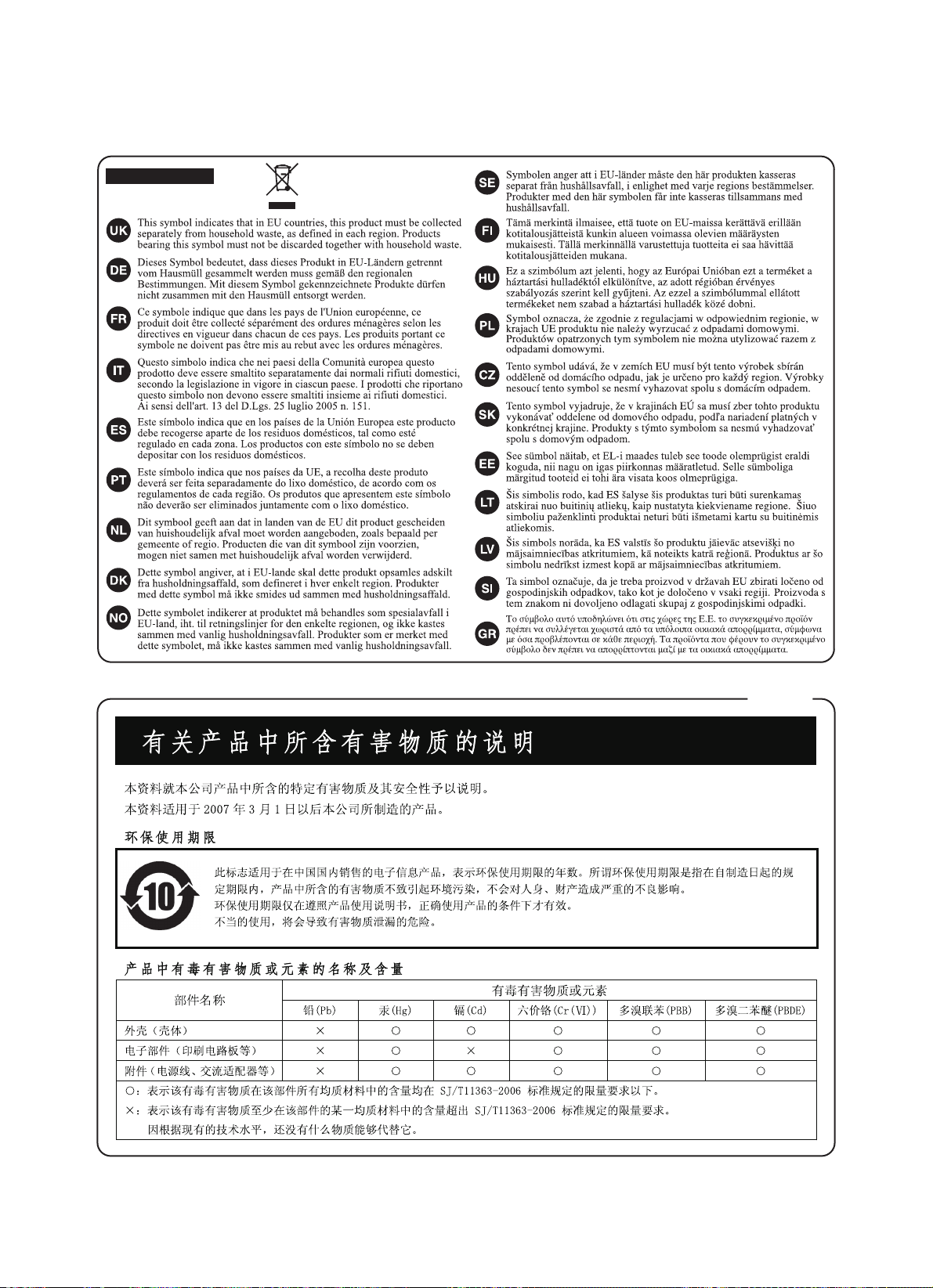
For EU Countries
For China
Page 19

As of Oct. 1, 2007 (ROLAND)
Information When you need repair service, call your nearest Roland Service Center or authorized Roland
distributor in your country as shown below.
EGYPT
Al Fanny Trading Oce
9, EBN Hagar Al Askalany Street,
ARD E1 Golf, Heliopolis,
Cairo 11341, EGYPT
TEL: (022)-418-5531
REUNION
Maison FO - YAM Marcel
25 Rue Jules Hermann,
Chaudron - BP79 97 491
Ste Clotilde Cedex,
REUNION ISLAND
TEL: (0262) 218-429
SOUTH AFRICA
T.O.M.S. Sound & Music (Pty)Ltd.
2 ASTRON ROAD DENVER
JOHANNESBURG ZA 2195,
SOUTH AFRICA
TEL: (011)417 3400
Paul Bothner(PTY)Ltd.
Royal Cape Park, Unit 24
Londonderry Road, Ottery 7800
Cape Town, SOUTH AFRICA
TEL: (021) 799 4900
CHINA
Roland Shanghai Electronics
Co.,Ltd.
5F. No.1500 Pingliang Road
Shanghai 200090, CHINA
TEL: (021) 5580-0800
Roland Shanghai Electronics
Co.,Ltd.
(BEIJING OFFICE)
10F. No.18 3 Section Anhuaxili
Chaoyang District Beijing 100011
CHINA
TEL: (010) 6426-5050
HONG KONG
Tom Lee Music Co., Ltd. Service
Division
22-32 Pun Shan Street, Tsuen
Wan, New Territories,
HONG KONG
TEL: 2415 0911
Parsons Music Ltd.
8th Floor, Railway Plaza, 39
Chatham Road South, T.S.T,
Kowloon, HONG KONG
TEL: 2333 1863
INDIA
Rivera Digitec (India) Pvt. Ltd.
411, Nirman Kendra Mahalaxmi
Flats Compound O. Dr. Edwin
Moses Road, Mumbai-400011,
INDIA
TEL: (022) 2493 9051
INDONESIA
PT Citra IntiRama
Jl. Cideng Timur No. 15J-15O
Jakarta Pusat
INDONESIA
TEL: (021) 6324170
KOREA
Cosmos Corporation
1461-9, Seocho-Dong,
Seocho Ku, Seoul, KOREA
TEL: (02) 3486-8855
MALAYSIA
Roland Asia Pacic Sdn. Bhd.
45-1, Block C2, Jalan PJU 1/39,
Dataran Prima, 47301 Petaling
Jaya, Selangor, MALAYSIA
TEL: (03) 7805-3263
VIET NAM
Suoi Nhac Company, Ltd
370 Cach Mang Thang Tam St.
Dist.3, Ho Chi Minh City,
VIET NAM
TEL: 9316540
PHILIPPINES
G.A. Yupangco & Co. Inc.
339 Gil J. Puyat Avenue
Makati, Metro Manila 1200,
PHILIPPINES
TEL: (02) 899 9801
SINGAPORE
SWEE LEE MUSIC COMPANY PTE.
LTD .
150 Sims Drive,
SINGAPORE 387381
TEL: 6846-3676
TAIWAN
ROLAND TAIWAN ENTERPRISE
CO., LTD.
Room 5, 9. No. 112 Chung Shan
N.Road Sec.2, Taipei, TAIWAN,
R.O.C.
TEL: (02) 2561 3339
THAILAND
Theera Music Co. , Ltd.
100-108 Soi Verng Nakornkasem,
New Road,Sumpantawongse,
Bangkok 10100 THAILAND
TEL: (02) 224-8821
AUSTRALIA/
NEW ZEALAND
Roland Corporation
Australia Pty.,Ltd.
38 Campbell Avenue
Dee Why West. NSW 2099
AUSTRALIA
For Australia
Tel: (02) 9982 8266
For New Zealand
Tel: (09) 3098 715
ARGENTINA
Instrumentos Musicales S.A.
Av.Santa Fe 2055
(1123) Buenos Aires
ARGENTINA
TEL: (011) 4508-2700
BARBADOS
A&B Music Supplies LTD
12 Webster Industrial Park
Wildey, St.Michael, Barbados
TEL: (246)430-1100
BRAZIL
Roland Brasil Ltda.
Rua San Jose, 780 Sala B
Parque Industrial San Jose
Cotia - Sao Paulo - SP, BRAZIL
TEL: (011) 4615 5666
CHILE
Comercial Fancy II S.A.
Rut.: 96.919.420-1
Nataniel Cox #739, 4th Floor
Santiago - Centro, CHILE
TEL: (02) 688-9540
COLOMBIA
Centro Musical Ltda.
Cra 43 B No 25 A 41 Bododega 9
Medellin, Colombia
TEL: (574)3812529
COSTA RICA
JUAN Bansbach Instrumentos
Musicales
Ave.1. Calle 11, Apartado 10237,
San Jose, COSTA RICA
TEL: 258-0211
CURACAO
Zeelandia Music Center Inc.
Orionweg 30
Curacao, Netherland Antilles
TEL:(305)5926866
DOMINICAN REPUBLIC
Instrumentos Fernando Giraldez
Calle Proyecto Central No.3
Ens.La Esperilla
Santo Domingo,
Dominican Republic
TEL:(809) 683 0305
ECUADOR
Mas Musika
Rumichaca 822 y Zaruma
Guayaquil - Ecuador
TEL:(593-4)2302364
EL SALVADOR
OMNI MUSIC
75 Avenida Norte y Final
Alameda Juan Pablo II,
Edicio No.4010 San Salvador,
EL SALVADOR
TEL: 262-0788
GUATEMALA
Casa Instrumental
Calzada Roosevelt 34-01,zona 11
Ciudad de Guatemala
Guatemala
TEL:(502) 599-2888
HONDURAS
Almacen Pajaro Azul S.A. de C.V.
BO.Paz Barahona
3 Ave.11 Calle S.O
San Pedro Sula, Honduras
TEL: (504) 553-2029
MARTINIQUE
Musique & Son
Z.I.Les Mangle
97232 Le Lamantin
Martinique F.W.I.
TEL: 596 596 426860
Gigamusic SARL
10 Rte De La Folie
97200 Fort De France
Martinique F.W.I.
TEL: 596 596 715222
MEXICO
Casa Veerkamp, s.a. de c.v.
Av. Toluca No. 323, Col. Olivar de
los Padres 01780 Mexico D.F.
MEXICO
TEL: (55) 5668-6699
NICARAGUA
Bansbach Instrumentos
Musicales Nicaragua
Altamira D'Este Calle Principal
de la Farmacia 5ta.Avenida
1 Cuadra al Lago.#503
Managua, Nicaragua
TEL: (505)277-2557
PANAMA
SUPRO MUNDIAL, S.A.
Boulevard Andrews, Albrook,
Panama City, REP. DE PANAMA
TEL: 315-0101
PAR AGU AY
Distribuidora De Instrumentos
Musicales
J.E. Olear y ESQ. Manduvira
Asuncion PARAGUAY
TEL: (595) 21 492147
PERU
Audionet
Distribuciones Musicales SAC
Juan Fanning 530
Miraores
Lima - Peru
TEL: (511) 4461388
TRINIDAD
AMR Ltd
Ground Floor
Maritime Plaza
Barataria Trinidad W.I.
TEL: (868) 638 6385
NORWAY
Roland Scandinavia Avd. Kontor
Norge
Lilleakerveien 2 Postboks 95
Lilleaker N-0216 Oslo
NORWAY
TEL: 2273 0074
POLAND
ROLAND POLSKA SP. Z O.O.
UL. Gibraltarska 4.
PL-03 664 Warszawa
POLAND
TEL: (022) 679 4419
PORTUGAL
Roland Iberia, S.L.
Portugal Oce
Cais das Pedras, 8/9-1 Dto
4050-465, Porto, PORTUGAL
TEL: 22 608 00 60
ROMANIA
FBS LINES
Piata Libertatii 1,
535500 Gheorgheni, ROMANIA
TEL: (266) 364 609
RUSSIA
MuTek
Dorozhnaya ul.3,korp.6
117 545 Moscow, RUSSIA
TEL: (095) 981-4967
SLOVAKIA
DAN Acoustic s.r.o.
Povazská 18.
SK - 940 01 Nové Zámky
TEL: (035) 6424 330
SPAIN
Roland Iberia, S.L.
Paseo García Faria, 33-35
08005 Barcelona SPAIN
TEL: 93 493 91 00
SWEDEN
Roland Scandinavia A/S
SWEDISH SALES OFFICE
Danvik Center 28, 2 tr.
S-131 30 Nacka SWEDEN
TEL: (0)8 702 00 20
SWITZERLAND
Roland (Switzerland) AG
Landstrasse 5, Postfach,
CH-4452 Itingen, SWITZERLAND
TEL: (061) 927-8383
UKRAINE
EURHYTHMICS Ltd.
P.O.Box: 37-a.
Nedecey Str. 30
UA - 89600 Mukachevo, UKRAINE
TEL: (03131) 414-40
UNITED KINGDOM
Roland (U.K.) Ltd.
Atlantic Close, Swansea
Enterprise Park, SWANSEA
SA7 9FJ,
UNITED KINGDOM
TEL: (01792) 702701
BAHRAIN
Moon Stores
No.1231&1249 Rumaytha
Building Road 3931, Manama 339
BAHRAIN
TEL: 17 813 942
IRAN
MOCO INC.
No.41 Nike St., Dr.Shariyati Ave.,
Roberoye Cerahe Mirdamad
Tehran, IRAN
TEL: (021)-2285-4169
ISRAEL
Halilit P. Greenspoon & Sons Ltd.
8 Retzif Ha'alia Hashnia St.
Tel-Aviv-Yafo ISRAEL
TEL: (03) 6823666
URUGUAY
Todo Musica S.A.
Francisco Acuna de Figueroa
1771
C.P.: 11.800
Montevideo, URUGUAY
TEL: (02) 924-2335
VENEZUELA
Instrumentos Musicales
Allegro,C.A.
Av.las industrias edf.Guitar import
#7 zona Industrial de Turumo
Caracas, Venezuela
TEL: (212) 244-1122
AUSTRIA
Roland Elektronische
Musikinstrumente HmbH.
Austrian Oce
Eduard-Bodem-Gasse 8,
A-6020 Innsbruck, AUSTRIA
TEL: (0512) 26 44 260
BELGIUM/FRANCE/
HOLLAND/
LUXEMBOURG
Roland Central Europe N.V.
Houtstraat 3, B-2260, Oevel
(Westerlo) BELGIUM
TEL: (014) 575811
CROATIA
ART-CENTAR
Degenova 3.
HR - 10000 Zagreb
TEL: (1) 466 8493
CZECH REP.
CZECH REPUBLIC DISTRIBUTOR
s.r.o
Voctárova 247/16
CZ - 180 00 PRAHA 8,
CZECH REP.
TEL: (2) 830 20270
DENMARK
Roland Scandinavia A/S
Nordhavnsvej 7, Postbox 880,
DK-2100 Copenhagen
DENMARK
TEL: 3916 6200
FINLAND
Roland Scandinavia As, Filial
Finland
Elannontie 5
FIN-01510 Vantaa, FINLAND
TEL: (0)9 68 24 020
GERMANY
Roland Elektronische
Musikinstrumente HmbH.
Oststrasse 96, 22844 Norderstedt,
GERMANY
TEL: (040) 52 60090
GREECE/CYPRUS
STOLLAS S.A.
Music Sound Light
155, New National Road
Patras 26442, GREECE
TEL: 2610 435400
HUNGARY
Roland East Europe Ltd.
Warehouse Area ‘DEPO’ Pf.83
H-2046 Torokbalint, HUNGARY
TEL: (23) 511011
IRELAND
Roland Ireland
G2 Calmount Park, Calmount
Avenue, Dublin 12
Republic of IRELAND
TEL: (01) 4294444
ITALY
Roland Italy S. p. A.
Viale delle Industrie 8,
20020 Arese, Milano, ITALY
TEL: (02) 937-78300
JORDAN
MUSIC HOUSE CO. LTD. FREDDY
FOR MUSIC
P. O. Box 922846
Amman 11192 JORDAN
TEL: (06) 5692696
KUWAIT
EASA HUSAIN AL-YOUSIFI &
SONS CO.
Al-Yousi Service Center
P.O.Box 126 (Safat) 13002 KUWAIT
TEL: 00 965 802929
LEBANON
Chahine S.A.L.
George Zeidan St., Chahine Bldg.,
Achraeh, P.O.Box: 16-5857
Beirut, LEBANON
TEL: (01) 20-1441
OMAN
TALENTZ CENTRE L.L.C.
Malatan House No.1
Al Noor Street, Ruwi
SULTANATE OF OMAN
TEL: 2478 3443
QATAR
Al Emadi Co. (Badie Studio &
Stores)
P.O. Box 62, Doha, QATAR
TEL: 4423-554
SAUDI ARABIA
aDawliah Universal Electronics
APL
Behind Pizza Inn
Prince Turkey Street
aDawliah Building,
PO BOX 2154,
Alkhobar 31952
SAUDI ARABIA
TEL: (03) 8643601
SYRIA
Technical Light & Sound Center
Rawda, Abdul Qader Jazairi St.
Bldg. No. 21, P.O.BOX 13520,
Damascus, SYRIA
TEL: (011) 223-5384
TURKEY
ZUHAL DIS TICARET A.S.
Galip Dede Cad. No.37
Beyoglu - Istanbul / TURKEY
TEL: (0212) 249 85 10
U.A.E.
Zak Electronics & Musical
Instruments Co. L.L.C.
Zabeel Road, Al Sherooq Bldg.,
No. 14, Ground Floor, Dubai,
U.A.E.
TEL: (04) 3360715
CANADA
Roland Canada Ltd.
(Head Oce)
5480 Parkwood Way Richmond B.
C., V6V 2M4 CANADA
TEL: (604) 270 6626
Roland Canada Ltd.
(Toronto Oce)
170 Admiral Boulevard
Mississauga On L5T 2N6 CANADA
TEL: (905) 362 9707
U. S. A.
Roland Corporation U.S.
5100 S. Eastern Avenue
Los Angeles, CA 90040-2938,
U. S. A.
TEL: (323) 890 3700
ASIA
AFRICA
AUSTRALIA/
NEW ZEALAND
EUROPE
CENTRAL/LATIN
AMERICA
MIDDLE EAST
NORTH AMERICA
Page 20

*5100005105 -02*
 Loading...