

Page 1
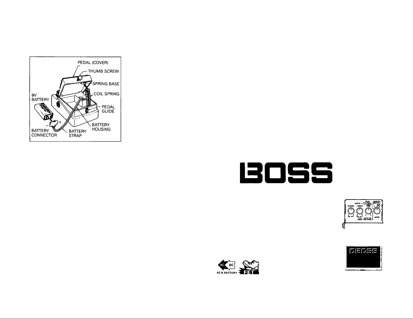
BATTERY REPLACEMENT
USE ONE 9-VOLT BATTERY
• Loosen the Screw of pedal to open it.
• Take out the battery from the Battery Housing
and disconnect the Battery Strap.
• Replace with a new battery and connect the
Battery Strap.
• Put the Coil Spring to the Spring Base and
close the Pedal.
• Make sure that the Battery Strap is not
caught in the Pedal or Coil Spring.
• Insert the screw into the Pedal Guide and
firmly tighten the screw.
RADIO AND TELEVISION INTERFERENCE
"Warning - This equipment has been verified to comply with the limits for a Class B computing device,
pursuant to Subpart J, of Part 15, of FCC rules. Operation with non>certified or non-verified equip
ment is likely to result in interference to radio and TV reception."
The equipment described in this manual generates and uses radio-frequency energy. If it is not
installed and used properly, that Is. in strict accordance with our instructions. It may cause interfer
ence with radio and television reception.
This equipment has been tested and found to comply with the limits for a Class B computing
device in accordance with the specifications in Subpart J. of Part 15, of FCC Rules. These rules are
designed to provide reasonable protection against such a interference in a residential installation.
However, there is no guarantee that the interference will not occur in a particular installation. If this
equipment does cause interference to radio or television reception, which can be determined by turning
the equipment on and off, the user is encouraged to try to correct the interference by the
following measure:
• Disconnect other devices and their input/output cables one at a time. If the interference stops, it
is caused by either the other device or its t 'O cable.
These devices usually require Roland designated shielded I/O cables. For Roland devices, you can
obtain the proper shielded cable from your dealer. For non Roland devices, contact the manufacturer
or dealer for assistance.
If your equipment does cause interference to radio or television reception, you can try to correct
the interference by using one or more of the following measures:
• Turn the TV or radio antenna until the interferences stops.
• Move the equipment to one side or the other of the TV or radio.
• Move the equipment farther away from the TV or radio.
• Plug the equiprnent into an outlet that is on a different circuit than the TV or radio. (That is, make
certain the equipment and the radio or television set are on circuits controlled by different circuit
breakers or fuses.)
• Consider installing a rooftop television antenna with coaxial cable lead-in between the antenna and
TV.
If necessary, you should consult your dealer or an experienced radio/television technician for
additional suggestions. You may find helpful the following booklet prepared by the Federal Com
munications Commision:
"How to Identify and Resolve Radio-TV Interference Problems"
This booklet is available from the U.S. Government Printing Office, Washington, D.C.. 20402
Stock No. 004-000-00345-4.
SPECIFICATIONS
Power
............................................
Current Draw
...............................
9V Dry Battery x 1, AC adaptor (BOSS PSA Series)
45 mA to 60mA (9VDC)
Controls ........................................Effect Level, Feedback Level, Time (Sampling/Delay)
Others
...........................................
Jacks
..............................................
Sampling Time
Delay Time
.............................
...................................
Frequency Response
................
Mode Selector Switch, Pedal Switch (Normal/Effect Selector
in Delay mode. Trigger Switch in Sampler mode)
LED Indicator (= Battery Check Indicator)
Input, Output, Trigger In, AC Adaptor (PSA Series)
200ms (MIN) to 800ms (MAX)
50ms (MIN) to 800ms (MAX)
Sampling/Delay sound: 40Hz to 7kHz (ijdB)
Direct Sound: 10 Hz to 60kHz (ii dB)
Residual Noise ............................Sampling/Delay mode: -95dBm (IHF-A)
Input Impedance .........................1 Mil (FET Input)
Normal mode: — lOOdBm or less (IHF-A)
Output Load Impedance
............
lOkilormore
Dimensions...................................70(W) x 55(H) x 125(D) mm/2%"(W) x 2yi6"{H) x 4'5/i6"(D)
Weight ...........................................450g/1lb
‘ Specifications are subject to change without notice.
Printed in Japan '85 Feb E-3
DSD-2
O
INSTRUCTIONS
FEATURES
The BOSS DSD-2 is an effect unit that features both the sampler func
tion 1800ms digital recorder) and the delay function (50 to 800ms).
The Trigger In Jack can be used to sync the OSD-2 with a rhythm
machine, or to sample a sound and use it as an external sound source,
or to obtain an echo effect that perfectly syncs to the rhythm.
> Please read these instructions carefully for proper operating procedures for the BOSS DSD-2.
Digital Sampler
/Delay
<-OUTPUT INPUT <-
Digital Sampler
/Delay DSD-2
T«G.IN<- I
Page 2
NOTICE
»Please be sure to use the AC Adaptor BOSS PSA-120, 220 or 240 depending on the voltage
system in your country. ACA-series can not be used, as the DSD-2 draws more current (4560mA 9V DC) than usual compact effect units.
»The battery (one Dry Battery. 9V) will last for 30 minutes to 2 hours (manganese) or 5 to 10
hours (alkaline), depending on the conditions. The use of a BOSS PSA-Adaptor and alkaline
battery is recommended for a longer time performance.
»Avoid using this unit in extreme heat or humidity, or where it may be affected by dust.
CAUTIONS
»When the unit is not in use for a long
period, remove the battery to prevent pro
blems caused by the battery leakage.
»if the battery voltage drops, effect becomes
vague or no sound is produced. To prevent
that, replace the battery.
AC ADAPTOR (OPTION)
»Be sure to keep the battery securely con
nected even while using the AC Adaptor,
then the unit will continue to operate even
if the AC Adaptor cord comes out during
performance.
»To avoid wasting the battery unplug the
cord from the OUTPUT jack when the unit
is not in use.
> For AC operation, be sure to use the BOSS
AC Adaptor PSA-120, 220 or 240 depending
on the voltage system in your country, and
never use one Adaptor for two units simul
taneously.
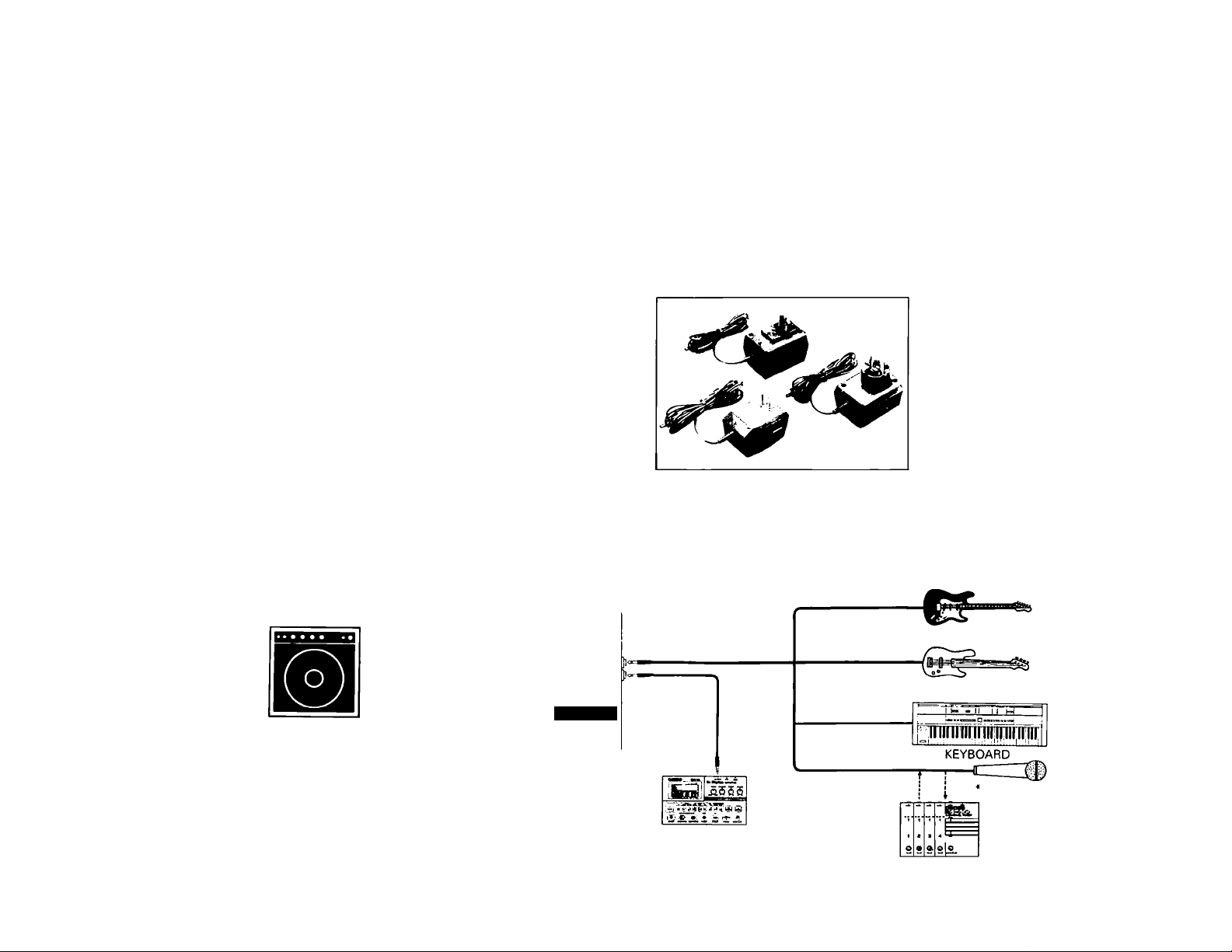
CONNECTING
( Be sure to take off connecting plug from the Output when the unit is not used. ^
Power is switched on
when a plug is put
into Output Jack. (In
battery operation)
AMPLIFIER
•The microphone can be directly connected to the Input Jack
only when it has sufficient output.
i
ÔôôitS
^output «#014-
Olgitol Somplar
/0«tog oso-2
r:r=PF!=
DSD-2
TO AC Adaptor Jack
AC ADAPTOR
BOSS PSA-series
Rhythm Machine with
Trigger Output
(e.g. BOSS DR-110)
ELECTRIC GUITAR
BASS GUITAR
MICROPHONE
Preamplifier, Mixer
(e.g. BOSS BX-400)
Page 3

PANEL DESCRIPTION
OAC ADAPTOR JACKO CHECK INDICATOR
©EFFECT LEVEL KNOB-
O feedback level knob
©OUTPUT JACK
-------------
^OUTPUT INPUTS
TRIG.IN<-
Digital Sampler
/Delay dsd-2
©TIME KNOB
©MODE SELECTOR
SWITCH
©INPUT JACK
©TRIGGER IN JACK
©PEDAL SWITCH
©THUMB SCREW
OAC ADAPTOR JACK
This is to connect an AC adaptor (BOSS PSA
series).
Connecting the AC adaptor to this jack will
turn the DSD-2 on. (While the AC Adaptor is
connected, the Output Jack O does not work
as ON/OFF switch.)
• Please note that the BOSS ACA series AC
adaptors do not match the OSO-2 because of
rated current difference.
©CHECK INDICATOR
[Delay Mode]
This indicator lights up when the effect is
turned on. and goes out when off.
[Sampler Mode]
The indicator lights up while the sampled
sound is being recorded or played.
•Check Indicator also serves as the power
indicator. When the DC supply being fed is
not enough for the DSD-2 to operate, the
indicator fails to light.
©EFFECT LEVEL KNOB
This knob is to adjust the level of the delay/
sample sound. Rotating this knob clockwise
increases the volume of effect sounds. At the
MAX position the delay/sample sound level
becomes equal to that of direct sound, and at
the MIN position only the direct sound is
heard.
©FEEDBACK LEVEL KNOB
[Delay Mode]
In this mode, this knob decides how many
times the delay sound is to be repeated.
Rotating this knob clockwise increases the
number. At the fully counterclockwise posi
tion single delay will be obtained.
[Sampler Mode]
In this mode, the knob should be set at the
lully counterclockwise position. Rotating the
knob clockwise mixes recorded sound with
the sample sound and an effect like multitrack
recording is obtained.
©OUTPUT JACK
This is to connect to the external amplifier.
Direct and delay/sample sounds are mixed
and sent out through this jack.
•The Output Jack serves as a power switch,
that is. the DSD-2 will be turned on by plug
in a connection cord, and turned off by
disconnecting it. (This applies only while
the unit is operating on battery.)
©TIME KNOB
[Delay Mode]
In this mode, the knob determines the delay
time. Rotating it clockwise will make longer
delay time. This knob actually changes the
delay time set by the Mode Selector Switch
from " X 0.25" to " X 1" continuously.
[Sampler Mode]
In this mode, the knob determines the sampling
time Irom 200 to 800ms. Rotating this
clockwise will make the lime longer.
©MODE SELECTOR SWITCH
Four modes are optional with this switch: two
Delay modes and two Sampler modes as follows.
[Delay Modes]
At S the range is 200ms. By using the Time
Knob the delay time can be changed continu
ously from 50 to 200ms.
At L the range is 800ms. The delay time can
be changed continuously Irom 200ms to
800ms with the Time Knob.
[Sampler Modes]
REC/PLAY: The recorded sound is played and
new sound is simultaneously recorded.
PLAY ONLY: The sound recorded in REC/
PLAY mode is sustained and played.
•The sound is sustained until the power is
turned off or different mode is selected.
• In the Sampler mode, recording or playing is
started by pressing the pedal or feeding an
external trigger signal through the Trigger In
Jack.
•If the pedal switch is kept depressed, the
trigger is supplied continuously.
©INPUT JACK
This is to connect an electric instrument,
mike or the like.
•If the microphone has sufficient out
put. it can be directly connected to the
Input Jack. If not. use a mixer such as
BOSS BX-400 and/or preamplifier.
©TRIGGER IN JACK
This is to receive the signal sent from the Trig
ger Output of a rhythm machine.
©PEDAL SWITCH
[Delay Mode]
In this mode, the pedal switch works to turn
on or off the efiect.
[Sampler Mode]
In this mode, the pedal switch works as a trig
ger (start) switch (or recording or playing. If
the pedal is kept depressed, recording or play
ing is continuously repeated.
• Adopting the FET switch, the DSD-2 is free
from click noise.
©THUMB SCREW
Loosen this screw to open the cover for
battery replacement.
‘ Do not remove the screw
cover, or you may lose it.
from the
Page 4

OPERATION
— II] Delay Mode •
0 Make all the necessary connections, then set the controls c
the panel as shown left.
e Press the Pedal if the Check indicator is off. Now effect is on.
Dim or dark indicator means a poor or no power. Check the
power sjpply, AC adaptor or battery (when rrot using AC adaptorl.
*The DSO-2 takes for about 5 seconds to begin outputting effect
Sound after the pedal has been pressed. This is because of the
built-in muting circuit,
0 Select a delay time range with the Mode selector and set the
Time Knob to the desired position.
O With the Feedback Knob, set how many times the delay
sound is to be repeated.
■Oscillation may occur as you roíate the Feedback Knob
clockwise.
0 Set the level of the delay sound with the Effect Level Knob.
■ At the MAX position, the volume of the delay sound becomes
equal to the direct sound.
>[31 Application (Sync with programmable rhythm machine]"
O Connect ihe Trigger In Jack on the DSD-2 to the trigger out
put on the rhythm machine. (Other connections are the same as
above.)
' [2] Sampler Mode <
O Make all the necessary connections, then set the controls on
the panel as shown left.
0 The pedal switch serves as a recording start switch, so push
and quickly release the pedal in time to the sound to be recorded.
When the sampling time set with the Time Knob has been
elapsed, recording stops automatically.
■ If you press the pedal too late, the beginning of the sound will
be missed out, and if too early, silence will precede. Also, if you
keep pressing the pedal longer than the set sampling time,
recording/pfaying will be repeated, thereby the sound previ
ously recorded will be erased
0 Rotate the Feedback Knob fully clockwise and repeat the
step 0 for overdubbing.
O Set the Mode Selector Switch to the PLAY ONLY position and
press the pedal switch, and the sound recorded in the REC/PLAY
mode will be played. (It is also possible to play it by using the trigger
signal from the rhythm machine.) When the recording is unsatis
factory. repeat the step
0
0 By rotating the Time Knob, the pitch can be changed.
0 Set the controls on the panel as shown left, then enter the
trigger positions into the rhythm machine. Now. you can hear the
delay sound which perfectly syncs to the timing programmed in
the rhythm machine. (For instance, if you enter quarter notes,
the sound that is delayed precisely quarter note will be obtained.]
© Set how many timas the feedback is to be repeated and the
level of the delay sound as you like.
* By entering odd rhythms into the rhythm machine, you can
enjoy irregular repetition of the echo effect. Also, the echo can
be changed a u tome ties I Iv by the patterns you have entered.
•■Basically, the trigger cycle should be set
within the maximum delay time, but if it
happens to exceed it, It will sound like long
delay sound.
• Notes -
• If the sound gets muddy or beat is noticed,
change the tone color or slightly rotate the
Time Knob counterclockwise.
•The DSD-2's rated input level at the higher
frequency is lower than that at the lower
frequency. So. when you are using the instru
ment with high sound range or high harmonic
contents, the sound may be distorted. If this
happens, lower the input level.
 Loading...